
WRS 200 - Pest control Kärcher - Free user manual and instructions
Find the device manual for free WRS 200 Kärcher in PDF.
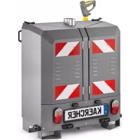


| Product type | Mounting kit for high-pressure cleaner (pest control) |
| Brand | Kärcher |
| Model | WRS 200 |
| Dimensions (L × W × H) | 550 mm × 955 mm × 1290 mm |
| Empty weight | 300 kg |
| Typical operating weight | 315 kg |
| Power supply | Hydraulic (PTO, 40 L/min) and integrated 12 V battery |
| Operating pressure | 1 to 20 MPa (max. 22 MPa) |
| Water flow rate | 28 L/min |
| Max. water temperature | 30 °C (supply); up to 98 °C for hot water |
| Fuel | Diesel (for burner) |
| Pump oil type | 15W-40 |
| Compatible vehicles | MIC 35/42, MIC 50/70, MC 130, MC 250 |
| Main functions | Hot water weed removal; cold water high-pressure cleaning |
| Optional accessories | Front bar WR 100 Adv, guns/lances (WR 10, WR 20, WR 50, WR 100) |
| Safety devices | Pressure switch, safety catch, water shortage safety, splash guard |
| Maintenance | Daily oil level check, water filter, maintenance tank RM 110; change every 50 h (1st time) then every 600 h |
| Sound level (LpA) | 79 dB(A) (uncertainty 3 dB(A)) |
| Hand-arm vibration | 1.5 m/s² (uncertainty 0.6 m/s²) |
| Warranty | According to country conditions; covers material or manufacturing defects |
Frequently Asked Questions - WRS 200 Kärcher
User questions about WRS 200 Kärcher
0 question about this device. Answer the ones you know or ask your own.
Ask a new question about this device
Download the instructions for your Pest control in PDF format for free! Find your manual WRS 200 - Kärcher and take your electronic device back in hand. On this page are published all the documents necessary for the use of your device. WRS 200 by Kärcher.
USER MANUAL WRS 200 Kärcher
Chairman of the Board of Management
S. Reiser
Director Regulatory Affairs & Certification
71364 Winnenden (Germany)
Tel.: +49 7195 14-0
Fax: +49 7195 14-2212
Winnenden, 2018/09/01
Contents
1 General 19 2 Warranty 20 3 Intended use 20 4 Safety instructions 20 5 WRS 200 device overview. 23 6 Requirements for operating the WRS 200. 24 7 Attach the adapter to the vehicle (platform C, D) .... 24 8 Fitting the adapter to the vehicle (platform E) 24 9 Attaching the top mount 25 10 Upper link position 25 11 Fitting and connecting the WRS 200. 25 12 Pre-commissioning 26 13 Startup 28 14 Operation 28 15 Storage 31 16 Care and maintenance. 31 17 Troubleshooting guide 32 18 Technical data 33 19 EU Declaration of Conformity 33
1 General
1.1 Description
CAUTION
Material damage through incorrect installation
Allow only qualified staff to perform the installation.
Note
Also adhere to the operating instructions of the vehicle on which the attached equipment is installed.
Keep these installation instructions for future reference or for future owners.
1.2 Environmental protection
The packing materials can be recycled. Please dispose of packaging in accordance with the environmental regulations.
Electrical and electronic appliances contain valuable, recyclable materials and often components such as batteries, rechargeable batteries or oil, which - if handled or disposed of incorrectly - can pose a potential threat to human health and the environment. However, these components are required for the correct operation of the appliance. Appliances marked by this symbol are not allowed to be disposed of together with the household rubbish.
Notes on the content materials (REACH)
Current information on content materials can be found at: www.kaercher.com/REACH
1.3 Checking the delivery
Please report any defects or shipping damage discovered immediately to your dealer or department store.
1.4 Scope of delivery
| Designation Order number | ||
| WRS 200 2.200-00 | 0.0* | |
| Adapter set PL-C, PL-D | 2.852-577.0** | |
| Adapter set PL-E (MC 250) | 2.852-959.0** | |
| Hydraulics set MIC 35/42 | 2.200-003.0*** | |
| Hydraulics set MIC 50/70 | 2.200-004.0*** | |
| Hydraulics set MC 130 | 2.200-005.0*** | |
| Hydraulics set MC 250 | 2.200-012.0*** | |
| Water connection attachment kit (MC 130) | 2.200-008.0 *** | |
| Water connection attachment kit (MC 250) | 2.200-013.0 *** | |
| Wiring harness (MC 250) | 4.839-790.0 *** | |
- included in scope of delivery ** is additionally required *** required depending on the vehicle
1.4.1 Accessories and spare parts
Only use original accessories and original spare parts.
They ensure that the appliance will run fault-free and safely.
Information on accessories and spare parts can be found at www.kaercher.com.
1.4.2 Optional accessories
| Designation Order number | ||
| WR 100 Adv 2.20 | 0-009.0 (MIC 35/42)**2.200-010.0 (MIC 50/70)**2.200-011.0 (MC 130)**2.200-011.0 (MC 250)*** | |
| Spray lance setHigh-pressuregun | 2.200-002.0 | |
| WR 10 2.114-016 | 0*NoteOnly use only together with nozzle 2.114-004.0(not included in scope of delivery) | |
| WR 20 2.114-014 | 0* | |
| WR 50 2.114-013 | 0* | |
| WR 100 2.114-01 | 5.0* | |
- Can only be used in conjunction with the high-pressure gun spray lance set 2.200-002.0
- Can only be used in conjunction with the attachment kit for water connection 2.200-008.0 *** Can only be used in conjunction with attachment kit for water connection 2.200-013.0 and wiring harness 4.839-790.0
1.4.3 Licence plate
A licence plate (repeater licence plate) must be attached before use on public roads.
A damaged blade guard must not be used.
① Licence plate position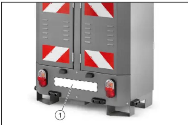
2 Warranty
The warranty conditions issued by our relevant sales company apply in all countries. We shall remedy possible malfunctions on your appliance within the warranty period free of cost, provided that a material or manufacturing defect is the cause. In a warranty case, please contact your dealer (with the purchase receipt) or the next authorised customer service site.
(See overleaf for the address)
3 Intended use
These operating instructions describe the handling of the WRS 200 attachment kit.
The attachment kit can be attached to the following vehicles using the corresponding adapter.
MIC 35/42 MIC 50/70 MC 130 MC250
The WRS 200 attachment kit is intended for the outdoor elimination of weeds using a hot water high-pressure cleaner and associated weeding tools.
The high-pressure cleaner can also be used for cleaning locations that are difficult to access.
The device may only be connected to the public water supply via a suitable backflow preventer.
The WRS 200 attachment kit may only be used for the intended use, as illustrated and described in these operating instructions.
Intended use also includes adherence to the prescribed servicing activities and intervals.
The vehicle and attachments may only be used, maintained and repaired by persons familiar with the vehicle and attachments and the associated hazards.
The legally applicable general safety and accident prevention regulations must be adhered to. All other safety regulations, occupational health care regulations and road traffic regulations must be adhered to.
The operating personnel must:
- Be physically and mentally suitable
- Have been instructed in the handling of the vehicle and attachments
- Have read and understood these operating instructions and the operating instructions for the vehicle to which this attachment kit is attached
- Have provided the operating company with verification of capability to operate the vehicle
- Be explicitly nominated to operate the vehicle by the operating company
4 Safety instructions
The following safety instructions apply to the device:
- Observe the respectively applicable national regulations for liquid jet cleaners.
- Observe the respectively applicable national accident prevention regulations. Liquid jet cleaners must be tested regularly and the results of the test recorded in writing.
- Note that the heating system in the device is classified as a furnace. Furnaces must be inspected regularly according to the applicable national regulations.
- According to the applicable national regulations, this device must be initially commissioned by a qualified person when used commercially. KÄRCHER has already
performed and documented this initial commissioning for you. You can request the documentation for this from your KÄRCHER partner. Please provide the part number and works number of the device when requesting documentation.
- We explicitly state that the applicable national regulations require that this device must be inspected regularly by a qualified person. Please contact your KÄRCHER partner for this.
- No modifications may be made to the device or accessories.
4.1 Battery
ATTENTION
Information on safety, charging, care and disposal of the battery is provided in the vehicle operating instructions. Always cover the plus terminal of the battery with the protective cap.
4.2 High-pressure hose
The following safety instructions apply to the high-pressure hose:
- Use only original high-pressure hoses.
- The high-pressure hose and the spray unit must be suitable for use at the maximum operating pressure specified in the technical data.
- Avoid contact with aggressive chemicals.
- Inspect the high-pressure hose daily. Do not continue using kinked hoses. Do not continue using the high-pressure hose if the outer wire mesh layer is visible.
- Do not continue using a high-pressure hose with a damaged thread.
- Lay the high-pressure hose so that it cannot be driven over or presents a tripping hazard to persons.
- A hose that has been driven over, kinked or subjected to impacts may no longer be used, even if no damage is visible.
- Store the high-pressure hose in a manner avoiding mechanical stresses on the hose.
4.3 Symbols on the device
Note
Replace the symbols immediately if they become illegible or get lost.
| △DANGER Risk of burns from hot surfaces Allow the vehicle to cool down before working on it. | |
| △WARNING Risk of injury from high-pressure jet Do not direct the high-pressure jet at persons, animals, live electrical equipment or at the device itself. Protect the device high-pressure cleaner frost. | |
| Warning of rotating tools | |
| Dangerous electrical voltage! Do not place any foreign objects or tools on the battery. |
| ATTENTION Danger of hearing damage Use suitable hearing protection when working with the device. |
| Wear suitable protective goggles when working with the device. |
| Wear protective gloves |
4.4 Safety devices
Safety devices protect the user and may not taken out of operation or functionally circumvented.
Adhere to the safety instructions in the chapters!
4.4.1 Pressure switch
When the trigger on the high-pressure gun is released, the pressure switch switches off the high-pressure pump and the high-pressure jet stops.
The pump switches on again when the trigger is pulled.
4.4.2 High-pressure gun safety latch
The safety latch on the high-pressure gun locks the trigger of the high-pressure gun.
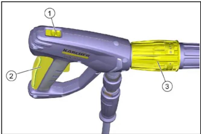
Safety latch
Front position: Trigger locked. Rear position: Trigger unlocked.
② Trigger ③ Pressure control
- Lock the trigger with the safety latch when not using the device.
4.4.3 Water shortage safeguard
The water shortage safeguard (flow switch) prevents the burner from overheating in the case of a shortage of water.
4.5 Hazard levels
DANGER
- Indication of an imminent threat of danger that will lead to severe injuries or even death.
WARNING
- Indication of a potentially dangerous situation that may lead to severe injuries or even death.
CAUTION
- Indication of a potentially dangerous situation that may lead to minor injuries.
ATTENTION
- Indication of a potentially dangerous situation that may lead to damage to property.
4.6 Protective gear
CAUTION: Wear suitable gloves when working with the device. Wear hearing protection whenever a sound pressure level over 80 dB(A) is specified in the operating instructions. See chapter Technical data in the operating instructions. Wear suitable protective clothing and safety goggles to protect yourself from water or dirt back-splash. Aerosols can be formed when using high-pressure cleaners. Inhaling aerosols can be harmful for your health. Employers are obliged to perform a hazard assessment in order to define, depending on the surface to be cleaned and the environment, protective measures necessary to prevent inhalation of aerosols. Respiratory protection masks of class FFP 2 or above are suitable for protection against aqueous aerosols.
4.7 General safety instructions
DANGER: Risk of asphyxiation. Keep packaging film out of the reach of children. WARNING: Only use the device for its proper use. Take into account the local conditions and beware of third parties, in particular children, when working with the device. The device is not intended for use by persons with restricted physical, sensory or mental abilities or those lacking in experience and/or lacking in knowledge. Only people who have been instructed on how to use the device, or have proven their ability to operate it, and have been explicitly instructed to use it, must use the device. Children must be supervised to prevent them from playing with the appliance. Children and minors must not use the device. CAUTION: Safety devices are provided for your own protection. Never modify or bypass safety devices.
4.8 Water connection
WARNING: The device must not be operated if the high-pressure hose is damaged. Replace a damaged high-pressure hose at once. Only those hoses and connections recommended by the manufacturer may be used. Note: The screw connections of all connection hoses must be leak-tight.
ATTENTION: Observe the regulations at your water distribution company. The device may only be connected to the public water supply via a suitable backflow preventer.
4.9 Operation
DANGER: When using the device in hazard zones (e.g. service stations), adhere to the respective safety regulations. Operation in explosive atmospheres is prohibited. Damaged wheels / tyre valves are extremely dangerous. Damaged wheels / tyre valves can be damaged by the high-pressure jet and explode. The first sign of this is discolouration of the tyres. Keep a spray distance of at least 30 cm when cleaning the wheels / tyre valves.
WARNING Do not use the device if people without the proper protective clothing are in its reach. With short spray lances, your hand may come into contact with the high-pressure jet. Never use a spotlight nozzle or rotary nozzle with steel tubes that are shorter than 75 cm . A recoil force will arise due to the water stream ejecting from the spray lance. An angular spray lance produces a force that acts in upward direction. Make sure you grip the gun and spray lance firmly. When using angular spray units, recoil forces and twisting forces may alter. Do not aim the
high-pressure jet at yourself, e.g. to clean clothes or shoes. Do not direct the high-pressure jet at persons, animals, live electrical equipment or at the device itself. Close the doors before driving. Do not spray any objects which contain harmful substances (e.g. asbestos). Check the device and the accessories, such as the high-pressure hose, high-pressure gun and safety devices, to make sure they are in proper safe and reliable condition before each operation. Do not use the device if it is damaged. Replace damaged components immediately. Only use high-pressure hoses, control panels and couplings specified by the manufacturer.
CAUTION Never leave the device unsupervised while it is in operation. Never open the cover while the motor is running. Never clamp the lever of the high-pressure gun during operation. Allow the hoses to cool down after hot water operation or operate the device briefly using cold water operation. The device must be placed on an even, firm subsurface. Before cleaning, carry out a risk assessment of the surface to be cleaned to determine any health and safety protection requirements. The necessary protective measures must be taken accordingly.
ATTENTION · Do not operate the device at temperatures below 0°C . Only clean the motor at washing stations with an oil separator.
4.9.1 Operation with detergent
CAUTION Keep the detergent out of the reach of children. When using detergents, observe the safety data sheet of the detergent manufacturer, in particular instructions on protective gear. Only use the detergents supplied or specified by the manufacturer. The use of other detergents or chemicals can impair the safety of the device. Should detergents come into contact with eyes, rinse these out immediately and thoroughly using water and seek medical attention immediately. The same applies if detergents are swallowed. Note The device may not be used for spreading pesticides.
4.9.2 Hot water burner
DANGER: Explosion hazard due to unsuitable fuel. Only fill the fuel specified in the operating instructions. Exhaust gases are toxic. Never breathe in the exhaust gases. Ensure rooms where the device is operated are sufficiently ventilated and that exhaust gases can be conducted away. WARNING: During tanking, make sure that no fuel gets on hot surfaces. CAUTION: Risk of burns. Never bend down over the exhaust gas opening and never reach inside it. Do not touch the heating boiler while the burner is in operation. - Never close off exhaust gas openings. - Make sure that no exhaust gases are emitted close to air vents. - Observe the safety instructions for petrol-driven devices in the operating instructions.
4.10 Care and service
WARNING: Always switch the device off prior to cleaning, maintenance and replacement of parts. Depressurise the high-pressure system prior to all work on the device or its accessories. CAUTION: Repairs may only be carried out by approved customer service sites or staff qualified in this area who are familiar with all relevant safety instructions.
ATTENTION: Pay attention to the safety inspection for mobile devices for industrial use in accordance with the locally applicable regulations. Short-circuits or other damage. Do not clean the device with a hose or high-pressure water jet. Do not use acetone, undiluted acids or solvents, as they corrode the materials used on the device.
4.11 Accessories and spare parts
CAUTION: Only use accessories and spare parts which are approved by the manufacturer. Only original accessories and original spare parts ensure that the appliance will run fault-free and safely. Only have repairs and installation of spare parts performed by the approved Customer Service in order to prevent any hazards.
5 WRS 200 device overview
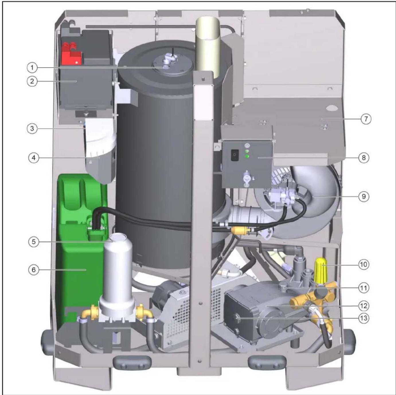
1 Burner sight glass, 2 Battery, 3 Dosing pump, 4 RM 110 container system care, 5 Water filter, 6 Fuel canister, 7 High-pressure hose storage compartment, 8 Control panel, 9 Burner blower, 10 Pressure control, 11 Filler opening lid
12 High-pressure pump, 13 Oil level sight glass
Note
Please note: All types of fuel are simply referred to as "fuel" in these operating instructions.
6 Requirements for operating the WRS 200
Note
Please consult Karcher-Service in the case of any uncertainties or questions.
- A suitably large water tank should be available in order to use the WRS 200.
- The water tank must be safely fastened to the rear of the vehicle.
- Attention must be paid to the maximum permissible weight and permissible axle loads of the vehicle when selecting the water tank.
- According to the attachment guideline, the outer edges must not protrude more than 400 mm beyond the contour of the vehicle. This is not conformant when no additional attachments are mounted (not permitted).
- Platform C and D
When the WRS 200 is mounted on the rear of the vehicle, a counterweight must be mounted on the front bar of the WR 100 Adv (weed elimination accessory) or another suitable counterweight must be mounted.
- Platform E (MC 250)
ATTENTION
Operation with the WRS 200 is only permitted in combination with the interchangeable frame (4.059-478.0).
Due to the maximum axle load of the vehicle, the waste water tank of the vehicle cannot be used and is automatically opened and forcibly emptied via software settings when WRS mode is selected. The waste water tank always remains open when the WRS 200 is in operation. Furthermore, when using the WR100 Adv, additional weights may not be used in the front area due to the axle loads.
Depending on the vehicle certification, a trailer coupling must or must not be attached. Existing fastening elements are to be used.
7 Attach the adapter to the vehicle (platform C, D)
The adapter with coupling triangle is attached to the rear of the vehicle for mounting the WRS 200.
① Adapter with coupling triangle ② Bolts with spring pins (2x) ③ Screws (2x)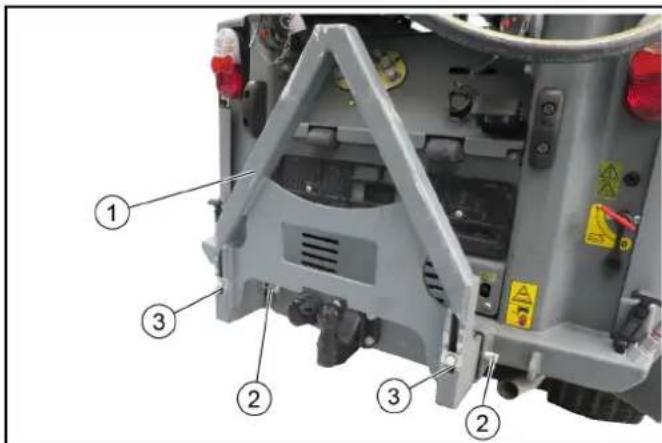
- Push the adapter into the mounting frame of the vehicle, observing the position of the various vehicles.
Figure: Installation on an MC 130 secured with a bolt and spring pin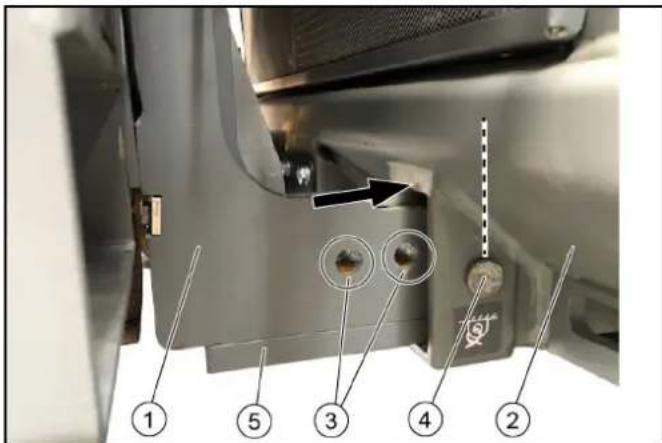
Adapter, vehicle mounting frame, position MIC 35/42 (platform C), position MC 130 (platform D), metal strip (2x)
Note
Required for installation on an MC 130
- MIC 35/42: Slide the adapter into the position (first or second hole) and secure it on the left and right with bolts and spring pins.
- MC 130: Fasten the metal strip at the bottom of the adapter. Slide in the adapter as shown in the illustration (third hole) and secure it on the left and right with bolts and spring pins.
- Tighten the screws to fasten the adapter firmly in place.
8 Fitting the adapter to the vehicle (platform E)
The adapter with coupling triangle is attached to the rear of the vehicle for mounting the WRS 200.
Adapter plate, M10x35 screws and washers (8x), trailer coupling (optional, depending on certification type). Adapter plate with coupling triangle. 1. Dismantle the adapter plate with the trailer coupling on the vehicle (8 screws and washers). 2. If necessary, fasten the existing trailer coupling to the adapter plate with M10x45 screws, washers and nuts (4x). 3. Hang up the adapter plate with the coupling triangle in the same way as above and fasten with 8 screws and washers.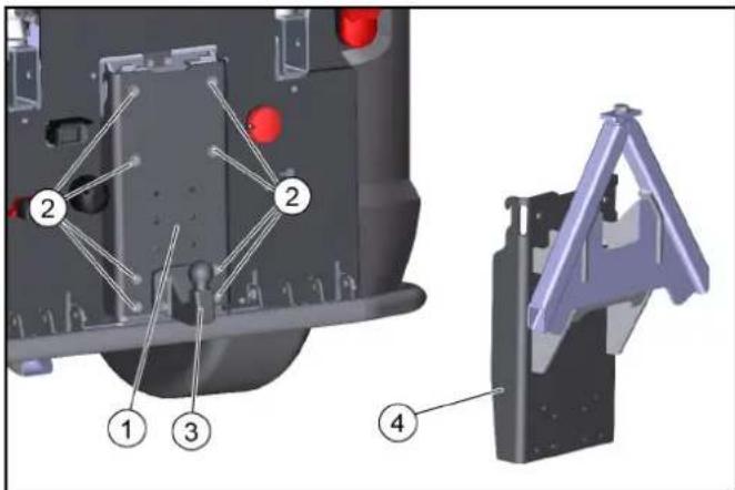
9 Attaching the top mount
The top mount stabilises the WRS 200 during operation and transport. It must be attached to the WRS 200 once only.
For the MIC 35/42 (platform C) and the MC 250 (platform E), mounting is performed below the air holes.
For the MC 130 or MIC 50/70 (platform D), mounting is performed above the air holes. The following description shows the mounting for platform D.
The holes for attaching the mount are already present. Unless specified otherwise, all nuts and screws are to be tightened to the standard torque.
Mounting to the carrier vehicle is made via 2 upper links. Mounting is described in a later chapter.
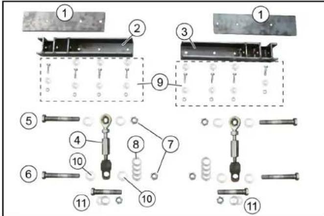
Top mount attachments
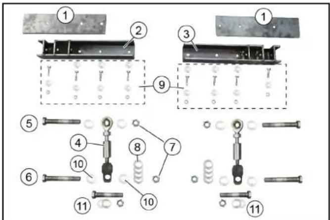
① Reinforcement plate (2x) ② Right-hand holder ③ Left-hand holder ④ Upper links (2x)
Note
For mounting to the carrier vehicle
⑤ Screws M16x120 (2x) ⑥ Screws M16x100 (2x) ⑦ M16 stop nuts (4x) ⑧ 18x200 washers (8x) ⑨ Mount fastening material
M8x30 screws (8x) - M8 nuts (8x) - 8x200 washers (14x)
10 16x200 washers (8x) Screw, washer, nut
For mounting the upper link on platform D
- Check the scope of delivery.
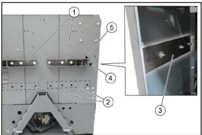
① Mount attachment for platform D (MC 130, MIC 50/70) ② Mount attachment for platform C (MIC 35/42) and platform E (MC 250)
③ Reinforcement plate
Outer screw
Note
Install this screw without a washer
⑤ Upper mount cutout
- Attach the reinforcement plate with mount on the WRS 200 (observe the correct mounting procedure according to the platform).
- Use screws with washers and nuts.
At the mount side: Fit the outer screw without a washer.
- Attach the right-hand mount in the same manner.
10 Upper link position
The upper link must be attached differently for platform C, platform D or platform E.
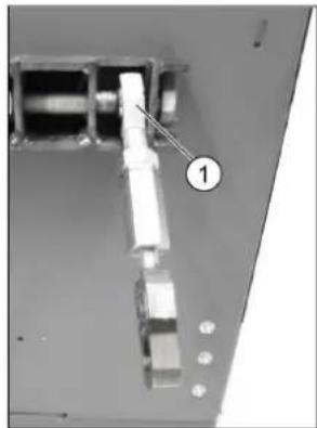
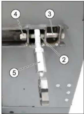
① Position for platform D
② Position for platform C and E ③ Screw ④ Stop nut ⑤ Upper link
- Attach the upper link in the corresponding position using a screw and stop nut.
11 Fitting and connecting the WRS 200
The WRS 200 is attached to the adapter with coupling triangle and secured by a screw.
It is additionally fastened to the vehicle by the upper links.
We recommend using the help of a second person for attaching the device.
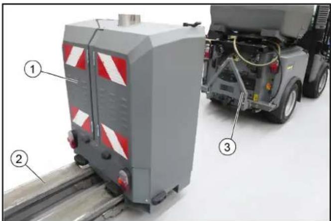
① WRS 200 ② Lift truck ③ Adapter with coupling triangle
- Use the lift truck to position the WRS 200 approximately 30 cm in front of the adapter and then lift it until it is positioned above the adapter.
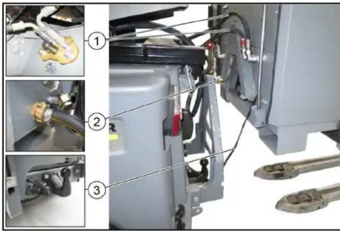
① Hydraulic hoses ② Water connection ③ Cable with plug 2. Connect the hydraulic hoses to the WRS 200 and insert them into the PTO hydraulic connection on the vehicle (observe the correct flow direction and, if applicable, the colour encoding). 3. Connect up the water hose. 4. Insert the cable with plug into the trailer socket.
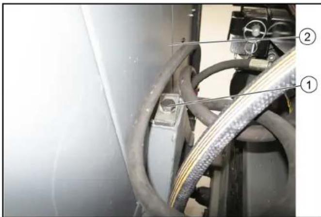
① Screw (retainer) ② WRS 200 5. Slowly move the WRS 200 forwards as far as it will go and then lower it into the adapter coupling triangle. 6. Secure the WRS 200 with the screw. Tightening torque 80 Nm.
Figure: Upper link fastener for platform C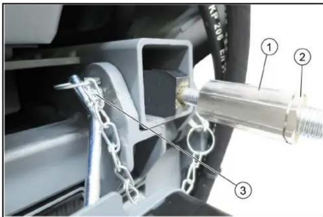
① Upper link adjusting nut
② Lock nut
③ Retaining pin with retaining clip (platform C)
- Attach the left-hand and right-hand upper links to the vehicle.
a) Platform C: Attach using the existing retaining pins on the vehicle and secure with the clips (see illustration). b) Platform D and E: Attach to the vehicle using screw, washers and nuts (included in scope of delivery) (see illustration).
Figure: Upper link fastener for platform D and E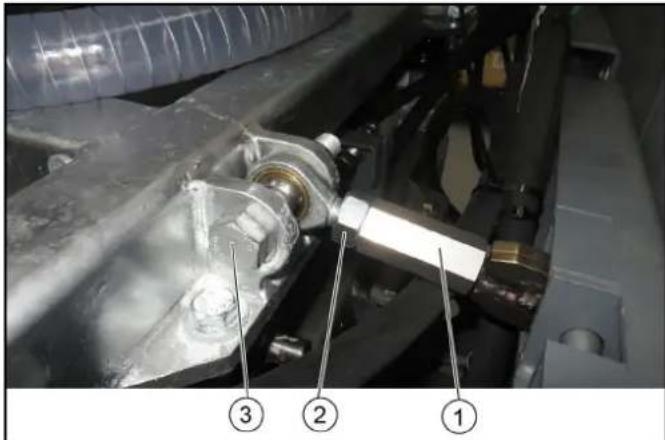
① Upper link adjusting nut ② Lock nut ③ Screw with washer and nut (platform D and E)
- Adjust the position of the WRS 200 using the adjusting nuts and secure with the counter-nuts.
12 Pre-commissioning
⚠ WARNING
Risk of injury
Check that the battery, accessories, supply lines, water filter and connections are in a correct condition before using the device.
Only use the device when it is in a correct condition.
- Check the filling level in the fuel canister and fill if necessary.
- Check the filling level in the system care container and fill with RM 110 if necessary.
- Check the filling level in the water tank and fill if necessary.
- A licence plate (repeater licence plate) must be attached before use on public roads. The license plate must be attached centrally with a 40 mm clearance, parallel to the tail lights.
12.1 Refuelling
DANGER
Explosion hazard due to overflowing fuel
Take care to ensure that no fuel spills onto hot surfaces when refuelling.
DANGER
Explosion hazard due to smoking and naked flames
Ensure strict prohibition of smoking and open flames during the refuelling procedure.
WARNING
Health risk from inhaled vapours
Do not refuel in confined spaces.
ATTENTION
Risk of damage due to incorrect fuel
Refuel with Diesel only.
ATTENTION
Risk of damage due to the fuel pump running dry
Check the filling level of the fuel canister regularly, refuel in time as necessary.
Note
Refill with fuel only when the canister is detached. Use only original canisters.
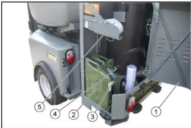
1Left-hand door
② Fuel canister ③ Retaining strap ④ Tank cap with fuel lines Detergent container
- Release the rubber latch on the left-hand door and open the door.
- Release the retaining strap from the canister.
- Open the tank cap and allow any fuel to drip off before removing the cap.
- Fasten the tank cap with fuel lines open at the top.
- Remove the canister.
- Refill with Diesel.
- Insert the canister and secure with the retaining strap.
- Fit the tank cap with fuel lines.
- Close the tank cap. 10. Wipe off any spilt fuel. 11. Close the left-hand door and secure with the rubber latch.
12.2 Filling the system care container
The RM 110 system care liquid (descaler) is a highly effective agent for preventing calcification of the heating coil when operating with hard water. This is drip-fed dosed into the water supply.
The dosage is set at the factory for water hardnesses of up to approx. 30°dH. The dosing valve can be adjusted if necessary. See chapter "Adjusting dosage".
ATTENTION
Health risk
Observe the safety and handling instructions for handling RM 110.
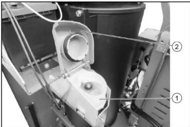
System care container
② Cover
- Open the lid of the system care container.
- Add RM 110 system care liquid to the container, do not overfill. Maximum filling level is 2 cm below the filling edge.
- Close the cover.
12.3 Adjusting the dosage
The dosage is set at the factory for water hardnesses of up to approx. 30°dH (position between 1 and 2). Change the position if necessary.
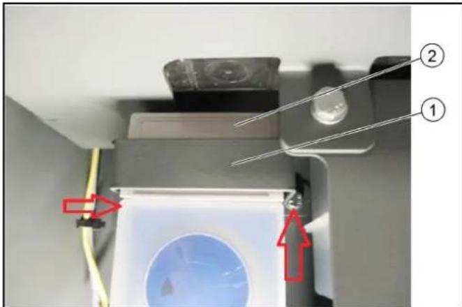
1 Bar
② Cover
- Remove the bar by removing the 2 screws (marked with arrows) using a socket wrench.
- Remove the cover.
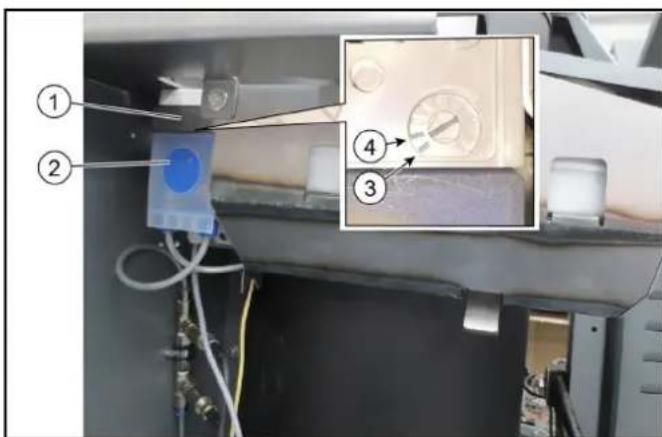
Cover ② Dosing pump ③ Position 1
Note
Up to 10°dH
④ Position 2
Note
Up to 55°dH
- Adjust position 1 to 2 for the desired degree of water hardness.
Higher positions are irrelevant because these degrees of hardness do not occur.
- Attach the cover.
- Attach the bar.
13 Startup
WARNING
Risk of injury from high-pressure jet or electric shock.
Check that the device, accessories, supply lines and connections are in a correct condition before using the device.
Only use the device when it is in a correct condition. 1.
13.1 Connect the high-pressure hose and high-pressure gun
The high-pressure hose is stored in a storage compartment behind the right-hand door.
The high-pressure gun with spray lance is located in holders attached to the left front side of the WRS 200.
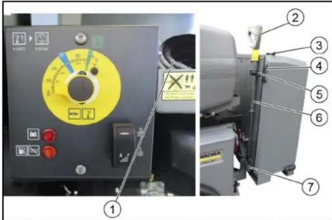
① High-pressure hose ② High-pressure gun ③ Left door rubber latch ④ Door handle ⑤ Holder with rubber latch Spray lance ⑦ Mounting
- Release the rubber latch on the right-hand door (at the top side) and open the door.
- Remove the high-pressure hose.
- Release the rubber latch from the upper holder.
- Remove the high-pressure gun with spray lance.
- Connect the high-pressure hose to the high-pressure gun.
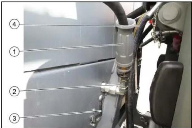
① High-pressure hose ② WRS 200 high-pressure connection 3Switchover valve
Upper position: Operation with high-pressure gun Lower position: Operation with high-pressure gun closed
Lower position (with front bar option): Switchover to front bar operation
Water hose to water connection
- Connect the high-pressure hose to the high-pressure connection.
13.2 Connecting the water hose
Establish the water supply to the WRS 200 (GEKA coupling). Ensure that the mains is disconnected!.
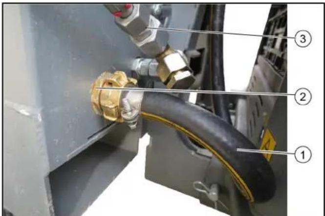
Water hose
② WRS 200 water connection
③ Front bar connection (option)
- Connect the water hose to the WRS 200.
14 Operation
ATTENTION
Pump running dry
Damage to the device
If pressure does not build up in the device after 2 minutes, switch the device off and proceed according to the instructions in the chapter "Help in case of malfunctions".
ATTENTION
Risk of damage
Always keep the doors closed when working and driving.
14.1 High-pressure cleaner
The high-pressure cleaner is operated by the hydraulic PTO connection on the vehicle.
The burner can be switched on for generating hot water.
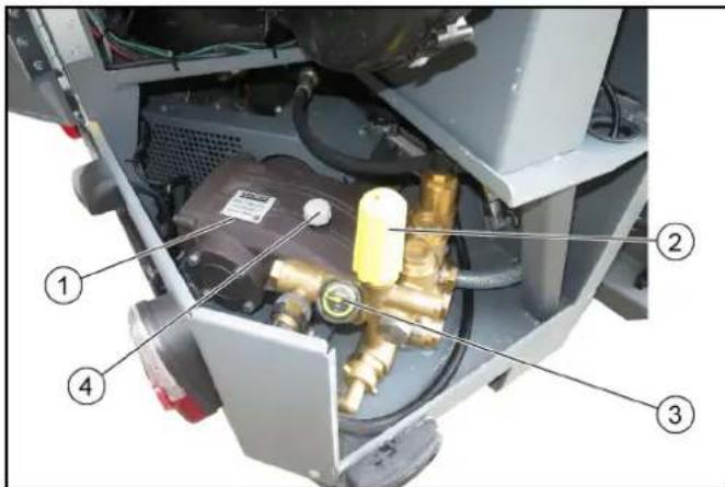
High-pressure cleaner ② Pressure control ③ Pressure gauge ④ Oil filler opening
- The high-pressure cleaner is intended for use as a hot water high-pressure cleaner for the elimination of weeds and as a cold water high-pressure cleaner for cleaning regions that are difficult to access.
- The water jet is applied using a high-pressure gun with spray lance and a corresponding nozzle attachment.
- Weed elimination can also be performed over larger areas using an optional front bar. Contact Kärcher for more information.
14.2 Control panel
The work temperature can be preselected at the temperature controller.
The burner does not switch on until the blower switch is switched on.
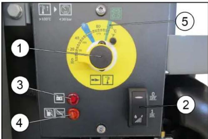
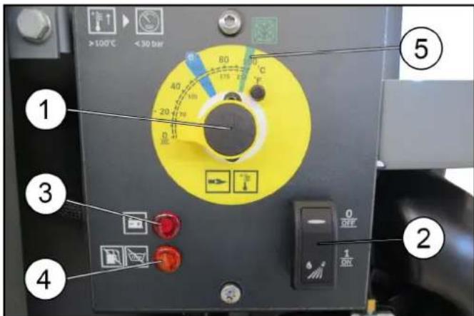
① Temperature limiter ② Burner blower on/off switch ③ Battery malfunction indicator 4 Warning light: cleaning container or fuel tank empty Note
When the warning light comes on, the burner switches off. Temperature setting 98°C (green marking) for fighting weeds.
- Set the temperature control to 98°C (green marking) and switch on the blower for fighting weeds. Switch off the blower switch immediately on completion of work to prevent the battery from being drained.
- For cold water high-pressure cleaning, turn the temperature control all the way to the left and switch off the blower.
14.3 Battery
The WRS 200 is equipped with an integrated battery that is charged by an alternator.
The battery is required for starting the burner.
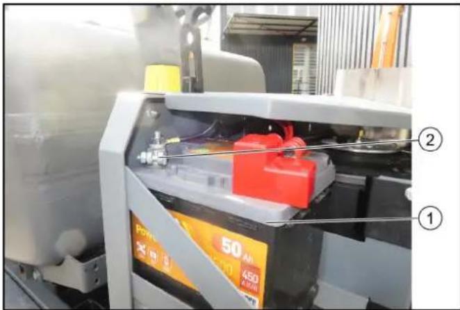
① Battery
② Minus terminal
- Please consult the operating instructions of the carrier vehicle for information on care, maintenance and safe handling of batteries.
- When storing the device for longer than 1 month, disconnect the minus terminal of the battery and recharge the battery every 2 months.
14.4 Eliminating weeds
Vehicle settings:
The procedure varies from vehicle to vehicle. Please refer to the operating instructions of the vehicle used for the exact procedure.
- PTO 40 litres/min Engine speed at least:
-MIC 35/42:2250 rpm - MIC 50/70:2100 rpm - MC 130:2400 rpm -MC250:1200rpm
- Deactivate the seat contact switch (when working with the standard high-pressure gun and spray lance accessories)
WRS 200 settings:
- Turn the temperature controller to 98°C (green marking on the temperature controller)
- Switch on the blower
- Fit the desired accessory (optional) to the spray lance
- Adjust the pressure control at the spray lance or at the high-pressure pump as required.
14.5 Cleaning with high pressure
Vehicle settings:
- PTO 40 litres/min
- Engine speed at least:
-MIC 35/42:2250 rpm -MIC 50/70:2100 rpm -MC 130:2400 rpm -MC 250:1200 rpm
- Deactivate the seat contact switch (when working with the standard high-pressure gun and spray lance accessories)
The procedure differs according to the vehicle and the vehicle operating instructions must be consulted.
WRS 200 settings:
- Set the temperature controller to 0°C (all the way to the left)
- Switch off the blower
- Fit the high-pressure nozzle to the lance
- Adjust the pressure control at the spray lance or at the high-pressure cleaner as required.
14.6 Working with the WRS 200
WARNING
Risk of injury due to recoil force
A recoil force will arise due to the water stream ejecting from the spray lance. Make sure you grip the high-pressure gun and spray lance firmly when working.
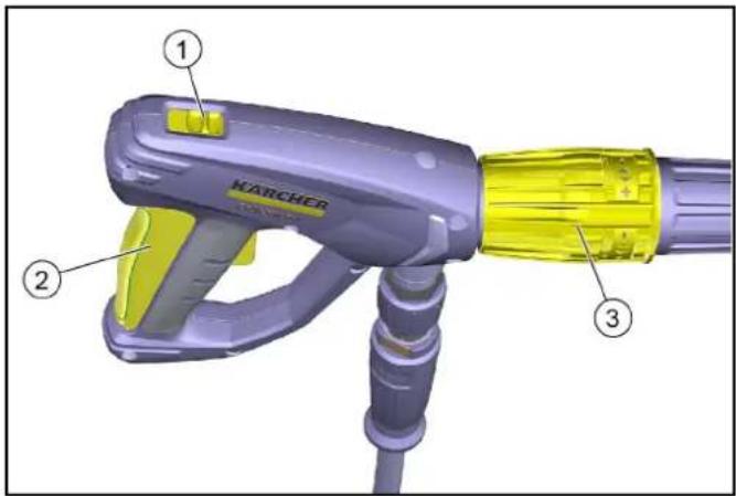
Safety latch ②Trigger Pressure control
- Unlock the safety latch on the high-pressure gun, rear position.
- Pull the trigger and commence working.
- Fight weeds with the hot water jet, working slowly
- As necessary: Adjust the pressure control at the spray lance or at the high-pressure cleaner as required.
14.7 Working with the WR 10 accessory (optional)
ATTENTION
Risk of damage to the spray head
Set the pressure regulation on the high-pressure pump to minimum pressure.
Additionally, use the 2.114-004.0 nozzle (not included in scope of delivery).
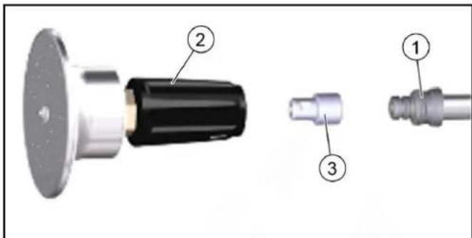
Lance ②WR 10 spray head ③ 2.114-004.0 nozzle
- Fasten the nozzle between the lance and the WR 10 spray head.
- Turn down the pressure regulation on the high-pressure pump to a minimum.
14.7.1 High-pressure gun and spray lance storage
Store the trigger gun with spray lance and high-pressure hose in the storage locations provided when driving on public roads or after finishing work.
14.8 Finishing work
- Park the vehicle and allow the engine to continue running.
- Set the temperature control to 0°C and switch off the burner blower.
- Operate the high-pressure cleaner in cold water mode until the high-pressure cleaner, high-pressure hose and high-pressure gun with spray lance have cooled down (danger of burns).
- Switch off the PTO work hydraulics.
- Switch off the engine.
- Close off the water inlet at the water tank.
- Press the trigger of the trigger gun and release the pressure remaining in the system.
- Secure the trigger with the safety latch.
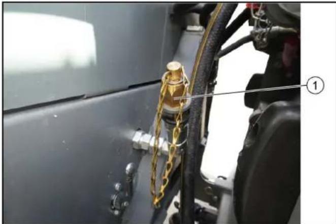
① Lock
- Unscrew the high-pressure hose from the high-pressure connection of the WRS 200. Fit a protective cap to prevent soiling.
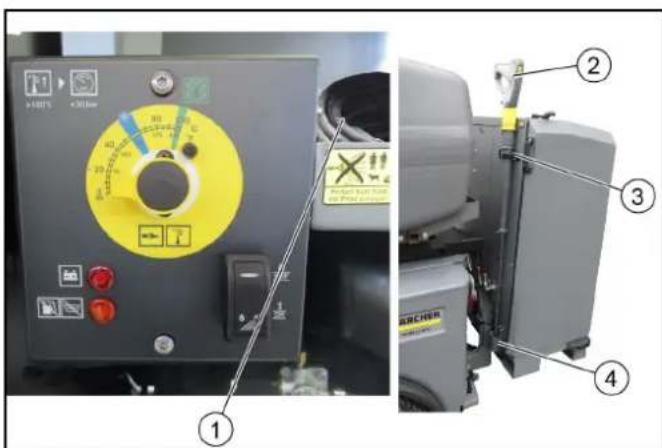
① Storing the high-pressure hose ② High-pressure gun with spray lance ③ Holder with rubber latch ④ Mounting
10. Fit the high-pressure gun with spray lance into the mount and holder and secure with the rubber retainer. 11. Open the right-hand door and place the high-pressure hose in the storage compartment.
15 Storage
CAUTION
Risk of injury and damage
Be aware of the weight of the device during storage.
16 Care and maintenance
16.1 Maintenance intervals
Note
In order to preserve warranty claims, all servicing and maintenance work during the warranty period has to be performed by an authorised Kärcher Customer Service, in accordance with the inspection check list.
| Time & date | Activity By whom | |
| Daily Check the oil level in the high-pressure pump, refill with oil if necessary | Operator | |
| Daily General visual inspection of the WRS 200 | Operator | |
| Daily Check the water filter, clean if necessary | Operator | |
| Daily Check the filling level in the system care container and fill with RM 110 if necessary | Operator | |
| Weekly Check the fastening screws for tight seating | Operator | |
| After the first 50 operating hours | Replace the oil in the high-pressure pump | Customer Service |
| Every 50 operating hours or weekly | Check the battery, see the information on the battery | Operator |
| Every 600 operating hours or annually | Replace the oil in the high-pressure pump | Customer Service |
16.2 Check/clean the water filter
① Casing ② Water filter ③ Seal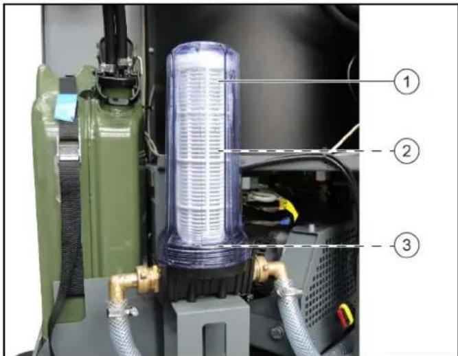
- Open the left-hand door.
- Visually check the water filter externally for soiling.
- For removing the water filter:
a. Close off the water inlet. b. Allow the pump to run briefly until the housing is empty. c. Unscrew and remove the casing. d. Check the seal and replace if necessary.
- Clean the water filter and replace if necessary.
Lubricate the housing seal and sealing surface of the water filter with silicone grease.
- Install in the reverse order.
- Open the water inlet.
16.3 Refilling oil in the high-pressure pump
CAUTION
Risk of burns!
Allow the high-pressure pump to cool down before refilling with oil.
ATTENTION
Check the oil level when the high-pressure pump has cooled down.
Note
The correct oil level is in the middle of the sight glass.
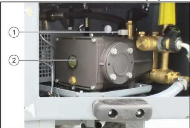
1. Check the oil level at the sight glass and refill with oil if necessary (to the middle of the sight glass). Oil type 15W-40. 2. Unscrew the cap from the oil filler opening. 3. Refill with oil. 4. Screw the cap onto the oil filler opening. 5. Wipe off any overflowed oil.
17 Troubleshooting guide
You can remedy minor faults using the following overview. If in any doubt, please contact your authorised Customer Service.
DANGER
Risk of injury
Switch off the carrier vehicle before carrying out any care and maintenance work.
DANGER
Risk of electric shock
Disconnect the plus terminal of the battery before carrying out any care and maintenance work.
ATTENTION
Repair work and work on electrical components must only be performed by your authorised Customer Service.
| Malfunction Cause Remedy | ||
| Battery malfunction indicator lights up | · Battery is not charging | · Contact Customer Service |
| System care container warning light lights up | · Container empty Note The burner switches off | · Refill with RM 110 system care liquid |
| The burner does not start up | · Fuel canister empty | · Refill Diesel |
| · Blower switch switched off | · Switch on the blower switch | |
| Burner emitting sooty smoke | · Burner incorrectly adjusted or dirty | · Contact Customer Service |
| · Fuel solenoid valve defective Note Diesel fuel continues dripping | · Contact Customer Service | |
| White smoke emitted from the burner | · No ignition spark present (visible through the sight glass in the burner cover) | · Contact Customer Service |
| · Condensation in the nozzle carrier | · Contact Customer Service | |
| · Fuel pressure too low | · Contact Customer Service | |
| Working pressure fluctuates | Leaks in the high-pressure pump suction area | 1. Check the piping system |
| Water filter dirty | 1. Clean/replace the water filter | |
| High-pressure pump not building up pressure | Nozzle clogged/washed out | 1. Clean/replace the nozzle |
| Supply line to high-pressure pump leaking or clogged | 1. Have this checked by Customer Service | |
| Safety valve leaking | 1. Have the setting and seals checked by Customer Service | |
| High-pressure pump knocking | Supply lines to high-pressure pump leaking | 1. Check and contact Customer Service if necessary |
| Water dripping out of the casing | High-pressure pump leaking | 1. Check, 3 drops of water per minute are normal In case of more serious leaks, have the device checked by Customer Service |
| Overflow valve continuously opening/closing (when the trigger gun is open) | Nozzle clogged | 1. Clean the nozzle |
| Overflow valve incorrectly adjusted/defective | 1. Have the overflow valve adjusted/replaced by Customer Service | |
| Device is scaled | 1. Contact Customer Service |
18 Technical data
WRS 200
Water connection
Feed pressure (max.) MPa 1
Input temperature (max.) °C 30
Input amount (min.) l/min 30
Minimum water supply hose diameter in 3/4
Device performance data
Nozzle size of standard nozzle 25070
Operating pressure MPa 1-20
Operating pressure (max.) MPa 22
Water flow rate l/min 28
Dimensions and weights
Weight kg 300
Typical operating weight kg 315
Length mm 550
Width mm 955
Height mm 1290
Operating materials
Fuel Diesel
Oil type 15W-40
Determined values in acc. with EN 60335-2-79
Hand-arm vibration value m/s2 1,5
Uncertainty K m/s2 0,6
Sound pressure level LpA dB(A) 79
Uncertainty KpA dB(A) 3
Subject to technical modifications.
19 EU Declaration of Conformity
We hereby declare that the machine described below complies with the relevant basic safety and health requirements in the EU Directives, both in its basic design and construction as well as in the version placed in circulation by us. This declaration is invalidated by any changes made to the machine that are not approved by us.
Product: High-pressure cleaner
Type: 2.200-xxx
Currently applicable EU Directives
2006/42/EC (+2009/127/EC)
2014/30/EU
2000/14/EC
ECE R 10
Harmonised standards used
EN 60335-1
EN 60335-2-79
EN 1829-1
EN 1829-2
EN ISO 12100:2010
EN 13309:2010
Conformity evaluation process used
2000/14/EC:Annex V
Sound power level
Measured: 96
Guaranteed: 99
The undersigned act on behalf and under the power of attorney of the company management.
H. Jenner
Chairman of the Board of Management
Documentation supervisor:
S. Reiser
Alfred Karcher SE & Co. KG
Alfred-Karcher-Str.28-40
71364 Winnenden (Germany)
Ph.: +49 7195 14-0
Fax: +49 7195 14-2212
Winnenden, 2018/09/01
S. Reiser
Director Regulatory Affairs & Certification
Content
2006/42/EC (+2009/127/EC)
2014/30/EU
2000/14/EC
ECER10
Chairman of the Board of Management
S. Reiser
Director Regulatory Affairs & Certification
Responsible for documentation:
S. Reiser
Alfred Kärcher SE & Co. KG
Alfred-Karcher-Str.28-40
71364 Winnenden (Germany)
Tel.: +49 7195 14-0
Fax: +49 7195 14-2212
Winnenden, 2018/09/01
Index
H. Jenner Chairman of the Board of Management
S. Reiser Director Regulatory Affairs & Certification
71364 Winnenden (Germany)
Tel.: +49 7195 14-0
Fax: +49 7195 14-2212
Winnenden, 2018/09/01
Contents
③ Position MIC 35/42 (platform C)
④ Position MC 130 (platform D)
⑤ Flat bar (2x)
Instruction
① Screw (locking) ② WRS200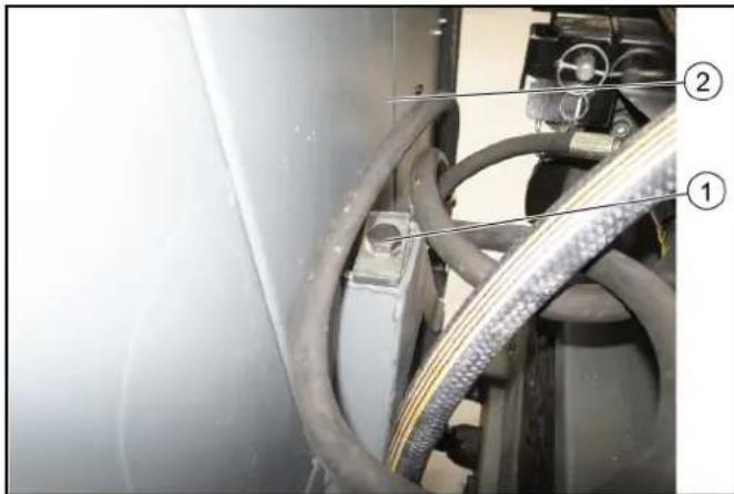
Chairman of the Board of Management
S. Reiser
Director Regulatory Affairs & Certification
71364 Winnenden (Germany)
Tel.: +49 7195 14-0
Fax: +49 7195 14-2212
Winnenden, 2018/09/01
Table of contents
2006/42/EC (+2009/127/EC)
2014/30/EU
2000/14/EC
ECER10
H. Jenner Chairman of the Board of Management
S. Reiser Director Regulatory Affairs & Certification
Responsible for documentation:
S. Reiser
Alfred Kärcher SE & Co. KG
Alfred-Karcher-Str.28-40
71364 Winnenden (Germany)
Tel.: +49 7195 14-0
Fax: +49 7195 14-2212
Winnenden, 01/09/2018
#
14.4 Removing weeds
Vehicle settings:
2006/42/EC (+2009/127/EC)
2014/30/EU
2000/14/EC
ECE R 10
Chairman of the Board of Management
S. Reiser
Director Regulatory Affairs & Certification
Winnenden, 01/09/2018
Contents
①Position for platform D
Danger of burns!
Transport volume, water l/min 28
Dimensions and weight
Weight kg 300
2006/42/EC (+2009/127/EC)
2014/30/EU
2000/14/EC
ECE R 10
2000/14/EC: Annex V
Sound power level
Measured: 96
Guaranteed: 99
Chairman of the Board of Management
S. Reiser
Director Regulatory Affairs & Certification
71364 Winnenden (Germany)
Tel.: +49 7195 14-0
Fax: +49 7195 14-2212
Winnenden, 2018/09/01
Contents
1 General 131 2 Warranty 132 3 Intended use 132 4 Safety instructions 132 5 Appliance overview WRS 200 135 6 Conditions for operating the WRS 200 135 7 Attach the adapter to the vehicle (platform C, D) 136 8 Mount the adapter on the vehicle (platform E) 136 9 Mount the upper holder 136 10 Positions for the upper bracket 137 11 Mount and connect the WRS 200 137 12 Before using the high-pressure washer 138 13 Starting up 140 14 Use 140 15 Storage 142 16 Care and maintenance 143 17 Troubleshooting 144 18 Technical data 145 19 EU declaration of conformity 145
1 General
1.1 Description
CAUTION
Position for platform D
12.3 Setting the dosage
The dosage is factory-set for a water hardness of up to approx. 30°dH (position between 1 and 2). Change the setting if necessary.
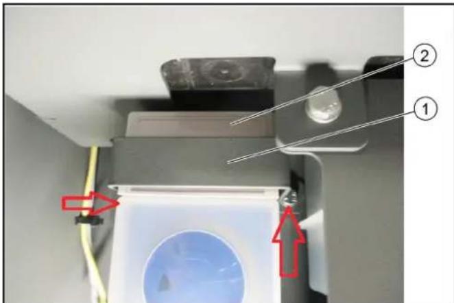
① Bracket ② Cover
Flow rate, water l/min 28
Dimensions and weight
Weight kg 300
2006/42/EC (+2009/127/EC)
2014/30/EU
2000/14/EC
ECE R 10
Harmonized standards applied
EN 60335-1
EN 60335-2-79
EN 1829-1
EN 1829-2
EN ISO 12100:2010
EN 13309:2010
Applied conformity assessment procedure
2000/14/EC: Annex V
Sound power level
Measured: 96
Guaranteed: 99
Chairman of the Board of Management
71364 Winnenden (Germany)
Tel.: +49 7195 14-0
Winnenden, 09/01/2018
Contents
(1) Screw, washer, nut
① Position for platform D
Chairman of the Board of Management
S. Reiser
Director Regulatory Affairs & Certification
Authorized for documentation:
S. Reiser
Alfred Kärcher SE & Co. KG
Alfred-Karcher-Str.28-40
D-71364 Winnenden (Germany)
Tel: +49 7195 14-0
Fax: +49 7195 14-2212
Winnenden, 2018/09/01
Contents
71364 Winnenden (Germany)
Phone: +49 7195 14-0
H. Jenner Chairman of the Board of Management
S. Reiser Director Regulatory Affairs & Certification
H. Jenner Chairman of the Board of Management
S. Reiser Director Regulatory Affairs & Certification
71364 Winnenden (Germany)
Tel: +49 7195 14-0
Fax: +49 7195 14-2212
Winnenden, 2018/09/01
Table of Contents
1 General information. 192 2 Warranty 193 3 Intended use 193 4 Safety information. 194 5 Device overview WRS 200 197 6 Prerequisites for operating the WRS 200. 197 7 Installing the adapter in the vehicle (C, D platform) 198 8 Installing the adapter in the vehicle (E platform) 198 9 Upper bracket installation 198 10 Upper connection positions 199 11 Installing and connecting the WRS 200. 199 12 Before initial operation 200 13 Commissioning 202 14 Operation 202 15 Storage. 205 16 Maintenance and care 205 17 Help in case of malfunction 206 18 Technical data 207 19 EU Declaration of Conformity 207
1 General information
1.1 Description
CAUTION
① Concept triangular adapter
2006/42/EC (+2009/127/EC)
2014/30/EU
2000/14/EC
ECE R 10
Chairman of the Board of Management
Winnenden, 2018/09/01
Contents
1 General information 208 2 Warranty 209 3 Intended use 210 4 Safety instructions 210 5 Overview of the WRS 200 device 214 6 Operating conditions for WRS 200 214 7 Installation of the antenna on the vehicle (platform C, D) 215 8 Installation of the antenna on the vehicle (platform E) 215 9 Installation of the upper bracket 216 10 Position of the central parts 216 11 Installation and connection of WRS 200 217 12 Before commissioning 218
13 Commissioning 219 14 Operation 220 15 Storage 222 16 Care and maintenance 222 17 Troubleshooting 224 18 Technical data 225 19 EC Declaration of Conformity 225
1 General information
1.1 Description
CAUTION
Material damage due to incorrect installation
Installation must only be carried out by qualified specialists.
Note
Also observe the instructions given in the operating manual of the vehicle on which the equipment is installed.
Keep the installation instructions for future use or for the next owner.
1.2 Environmental protection
Packaging materials are subject to mandatory recycling. The packaging must be disposed of without harm to the environment.
Electrical and electronic devices often contain valuable materials suitable for recycling, and frequently such components as batteries, accumulators, and oil, which, if improperly handled and inadequately disposed of, pose a potential hazard to health and the environment. Nevertheless, these components are necessary for the correct operation of the device. Devices marked with this symbol are prohibited from being disposed of with household waste.
Declaration on ingredients (REACH)
Dangerous electrical voltage! Do not place foreign objects or tools on the battery.

WARNING
Risk of damage to hearing
When working, use appropriate hearing protection.

Always use appropriate protective glasses.

Use protective gloves.
4.4 Protective devices
Protective devices serve to protect the user. Their disconnection or operation bypassing their functions is not permitted.
Follow the safety instructions contained in the chapters!
4.4.1 Pressure switch
When the trigger is pressed on the high-pressure cleaner, the pressure switch turns off the high-pressure pump, and the high-pressure jet stops.
When the trigger is released, the pump switches on again.
4.4.2 Trigger guard for high-pressure washer
The trigger guard on the high-pressure washer blocks the trigger.
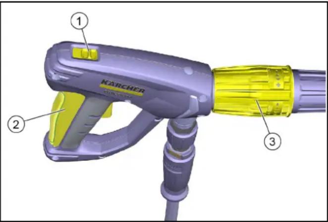
Trigger guard front position: lever locked front position: lever not locked ② Trigger ③Pressure regulator
- If the washer is not in use, lock the trigger with the trigger guard.
4.4.3 Dry-run protection device
The dry-run protection device (flow switch) prevents the burner from overheating when there is insufficient water.
4.5 Danger levels
DANGER
- Indicates an imminent danger that will result in serious injury or death.
WARNING
- Indicates a potentially dangerous situation that could result in serious injury or death.
CAUTION
- Indicates a potentially dangerous situation that could result in minor injury.
NOTICE
- Indicates a potentially dangerous situation that could result in property damage.
4.6 Personal protective equipment
WARNING: Always wear protective gloves when working with the device.
- Use hearing protection if the operating instructions specify a noise level above 80 dB(A); see the Technical
data section in the instructions. To protect against splashes, wear appropriate protective clothing and safety goggles. When using high-pressure devices, aerosols may form. Inhaling aerosols can be harmful to health. The operator must conduct a risk assessment to determine protective measures against aerosols, taking into account
the surface being cleaned and the working environment. For protection against oil aerosols, use respirators of class FFP 2 or higher.
4.7 General safety instructions
DANGER - Danger of suffocation. Keep the packaging film out of the reach of children. WARNING: Use the device only for its intended purpose. Consider local conditions and watch out for third parties, especially children, in the vicinity. The device is not intended for use by persons with reduced physical, sensory, or mental capabilities, or by persons lacking experience and/or knowledge. The device may only be used by persons who have read the instructions for handling it, have demonstrated their ability to control it, and have been instructed in its use. Ensure that children do not play with the device. It is forbidden for children and adolescents to work with the device. CAUTION - Protective devices are intended for your protection. It is forbidden to modify protective devices or to neglect them.
4.8 Water connection
WARNING: The device must not be put into operation with a damaged high-pressure hose. A damaged high-pressure hose must be replaced immediately. Only use hoses and connections recommended by the manufacturer. Note:
- The threaded connections of the connecting hoses must be tight.
ATTENTION: Follow the regulations of the local water supply company. Connection to the water supply is only permitted with a suitable backflow preventer.
4.9 Operation
DANGER: When using the device in hazardous areas (e.g., at filling stations), observe the applicable safety regulations. - Operation in potentially explosive atmospheres is prohibited. - Damaged tires / tire valves pose a danger to life. Tires / tire valves can be damaged by the water jet under pressure and burst. The first sign of this is a change in the tire's color. During cleaning of tires / tire valves, keep a distance of at least 30 cm from the jet. WARNING: Do not use the device if the trigger is not under protective clothing. With short spray lances, contact of the hand with the high-pressure jet is categorically prohibited. Do not use a turbo nozzle or a rotary nozzle with spray lances shorter than 75 cm. The water jet emerging from the spray lance creates a certain reaction force. Due to
The use of bent nozzles can change the spray direction. It is necessary to firmly hold the hose and the spray gun. When using bent nozzles, it is possible to change the force of recoil and twisting. Do not direct the spray at yourself, for example, to clean clothes or shoes. Do not direct the spray at people, animals, live electrical equipment, or at the device itself. Before starting movement, close the shut-off valve. Do not direct the spray at objects containing hazardous substances (for example, asbestos). Before each use, check the condition and operational safety of the device and accessories, for example, the high-pressure hose, high-pressure gun, and safety devices. Do not use the device if it is damaged. Replace damaged components immediately. Use only recommended high-pressure nozzles, fittings, and connecting elements from the manufacturer. CAUTION: It is strictly forbidden to leave the device running unattended. Do not open the housing while the device is running. During operation, the high-pressure gun must not be locked. After operation, let the device cool down for a short time before starting it with cold water. The device must stand on a level and stable surface. Before cleaning, a risk assessment must be carried out for the surface to be cleaned to determine safety and health protection requirements. Appropriate protective measures must be taken. ATTENTION: · Operation of the device at temperatures below 0°C is not permitted - Perform cleaning with a fuel-powered device with an oil separator.
4.9.1 Operating mode with cleaning agent
CAUTION: Store cleaning agents out of the reach of children. When using cleaning agents, it is necessary to pay attention to the safety data sheets of the manufacturers of the agents, especially the instructions for the use of personal protective equipment. Use only cleaning agents supplied or recommended by the manufacturer. The use of other cleaning agents or chemicals may have a negative impact on the safety of the device. - If cleaning agent gets into the eyes, rinse them thoroughly with water immediately and consult a doctor (the latter requirement also applies when swallowing cleaning agents). Note: - The use of pesticides is prohibited.
The required holes for installation of the fasteners are already present.
Unless otherwise specified, all screws and nuts must be tightened with the standard tightening torque.
Installation on the base transport vehicle is carried out with two central bolts. The installation is described in one of the following chapters.
Mounting parts of the upper fastening
Do not use the device if its condition is not perfect.
Do not use the device if its condition is not perfect.
1.
Minor faults can be rectified
by yourself with the help of the following description.
Sound power level
Measured: 96
Guaranteed: 99
This document was created electronically and is valid without a signature.
H. Jenner
Chairman of the Board of Management
S. Reiser
Director Regulatory Affairs & Certification
Person responsible for the document:
S. Reiser
Alfred Kärcher SE & Co. KG
Alfred-Karcher-Str.28-40
71364 Winnenden (Germany)
Tel.: +49 7195 14-0
Fax: +49 7195 14-2212
Chairman of the Board of Management
S. Reiser
Director Regulatory Affairs & Certification
Winnenden, 2018/09/01
Table of contents
1 General information 242 2 Warranty 243 3 Intended use 243 4 Safety instructions 244 5 Overview of WRS 200 equipment 247 6 Prerequisites for operating WRS 200 247 7 Connect adapter to vehicle (platform C, D) 248 8 Connect adapter to vehicle (platform E) 248 9 Mounting the upper bracket 248 10 Positions of the upper arm 249 11 Mounting and connecting WRS 200 249 12 Before commissioning 250 13 Commissioning 252 14 Operation 252 15 Storage 255 16 Care and maintenance 255 17 Troubleshooting 256 18 Technical data 257 19 EU declaration of conformity 257
1 General information
1.1 Description
△CAUTION
14.6 Working with WRS 200
△WARNING
Risk of injury from reactive force
2006/42/EC (+2009/127/EC)
2014/30/EU
2000/14/EC
ECE R 10
Chairman of the Board of Management
Authorized for documentation:
S. Reiser
Alfred Karcher SE & Co. KG
Alfred-Karcher-Str.28-40
Winnenden, 2018/09/01
S. Reiser
Director Regulatory Affairs & Certification
Table of Contents
1 General. 258 2 Warranty 259 3 Intended use 259 4 Safety instructions 260 5 Overview of the WRS 200 device. 263 6 Operating conditions for the WRS 200 device. 263 7 Installing the adapter on the vehicle (platform C, D) 264 8 Installing the adapter on the vehicle (platform E) 264 9 Installing the upper holder 264 10 Positions of the upper guide. 265 11 Install and connect the WRS 200 265 12 Before starting 266 13 Start-up 268 14 Operation 268 15 Storage 271 16 Care and maintenance 271 17 Troubleshooting 272 18 Technical data 273 19 EU Declaration of Conformity 273
1 General
1.1 Description
CAUTION
Risk of material damage due to incorrect installation
Installation may only be carried out by a qualified specialist.
Note
Also observe the operating instructions for the vehicle in which the connection device is installed.
Relevant EU Directives
2006/42/EC (+2009/127/EC)
2014/30/EU
2000/14/EC
ECE R 10
Chairman of the Board of Management
S. Reiser
Director Regulatory Affairs & Certification
①Regulator temperature
2006/42/EC (+2009/127/EC)
2014/30/EU
2000/14/EC
ECE R 10
Chairman of the Board of Management
Documentation administrator:
S. Reiser
Alfred Karcher SE & Co. KG
Alfred-Karcher-Str. 28 - 40
71364 Winnenden (Germany)
Tel.: +49 7195 14-0
S. Reiser Director Regulatory Affairs & Certification
Table of contents
Relevant EU Directives
2006/42/EC (+2009/127/EC)
2014/30/EU
2000/14/EC
ECE R 10
Harmonized standards applied
EN 60335-1
EN 60335-2-79
EN 1829-1
EN 1829-2
EN ISO 12100:2010
EN 13309:2010
Procedure applied for conformity assessment
2000/14/EC: Annex V
Chairman of the Board of Management
S. Reiser
Director Regulatory Affairs & Certification
Person responsible for compiling the documentation:
S. Reiser
Alfred Karcher SE & Co. KG
Alfred-Karcher-Str. 28 - 40
71364 Winnenden (Germany)
Tel.: +49 7195 14-0
Fax: +49 7195 14-2212
Winnenden, 2018/09/01
Contents
1 General information 308 2 Warranty 309 3 Intended use 309 4 Safety instructions 310 5 Overview of the WRS 200 device 313 6 Prerequisites for operating the WRS 200 313 7 Mounting the adapter on the vehicle (platform C, D). 314 8 Mounting the adapter on the vehicle (platform E). 314 9 Mounting the upper attachment 314 10 Positions of the upper control rod 315 11 Mounting and connecting the WRS 200 315 12 Before commissioning 316 13 Commissioning 318 14 Operation 318 15 Storage 321 16 Care and maintenance 321 17 Troubleshooting 322 18 Technical data 323 19 EU Declaration of Conformity 323
14.6 Working with the WRS 200
△WARNING
2006/42/EC (+2009/127/EC)
2014/30/EU
2000/14/EC
ECE R 10
2000/14/EC: Annex V
Chairman of the Board of Management
S. Reiser
Director Regulatory Affairs & Certification
71364 Winnenden (Germany)
Tel.: +49 7195 14-0
Fax: +49 7195 14-2212
Winnenden, 01.09.2018
Contents
1 General 324 2 Warranty 325 3 Proper use 325 4 Safety instructions 325 5 Overview of the WRS 200 device 328 6 Prerequisites for operating the WRS 200 attachment 329 7 Attach the adapter to the vehicle (platform C, D) 329 8 Place the adapter on the vehicle (platform E) 329 9 Mounting the upper receiver 330 10 Positions of the upper coupling 330 11 Setting up and connecting the WRS 200 attachment 330 12 Transfer work 331 13 Starting up 333 14 Operation 333 15 Storage 336 16 Care and maintenance 336 17 Troubleshooting 337 18 Technical data 338 19 EU declaration of conformity 338
1 General
1.1 Description
△CAUTION
Material damage due to incorrect mounting
2006/42/EC (+2009/127/EC)
2014/30/EU
2000/14/EC
ECE R 10
Applied harmonized standards
EN 60335-1
EN 60335-2-79
EN 1829-1
EN 1829-2
EN ISO 12100:2010
EN 13309:2010
Chairman of the Board of Management
S. Reiser
Director Regulatory Affairs & Certification
Winnenden, 2018/09/01
Table of Contents
1 General information 339 2 Warranty 340 3 Intended use 340 4 Safety instructions 341 5 Overview of the WRS 200 device 344 6 Prerequisites for operating the WRS 200 344 7 Mounting the adapter on the vehicle (platform C, D).... 345 8 Mounting the adapter on the vehicle (platform E) 345 9 Mounting the upper receiver 345 10 Position of the upper handle 346 11 Setting up and connecting the WRS 200 346 12 Before commissioning 347 13 Commissioning 349 14 Operation 349 15 Storage 352 16 Care and maintenance 352 17 Troubleshooting 353 18 Technical data 354 19 EU declaration of conformity 354
1 General information
1.1 Description
△CAUTION
Material damage due to incorrect installation
Installation must only be carried out by a qualified specialist.
Note
Also pay attention to the operating instructions of the vehicle in which the built-in device is installed.
Keep the installation instructions for future use or for the next owners.
2006/42/EZ (+2009/127/EZ)
2014/30/EU
2000/14/EZ
ECE R 10
Applied harmonized standards
EN 60335-1
EN 60335-2-79
EN 1829-1
EN 1829-2
EN ISO 12100:2010
EN 13309:2010
Chairman of the Board of Management
Person authorized for documentation:
S. Reiser
Alfred Karcher SE & Co. KG
Alfred-Karcher-Str.28-40
71364 Winnenden (Germany)
Tel.: +49 7195 14-0
Director Regulatory Affairs & Certification
Contents
1 Safety instructions 355 2 Intended use 356 3 Safety instructions 356 4 Safety instructions 357 5 Overview of WRS 200 360 6 Operating conditions for WRS 200 360 7 Mounting the adapter on the vehicle (platform C, D) 361 8 Mounting the adapter on the vehicle (platform E) 361 9 Mounting the top support 362 10 Positioning the fuel tank 362 11 Connecting and coupling the WRS 200 363 12 Before commissioning 364 13 Starting operation 365 14 Operation 366 15 Storage 368 16 Care and maintenance 368 17 Troubleshooting 370 18 Technical data 371 19 EC Declaration of Conformity 371
1 General information
1.1 Description
△DANGER
Material damage and personal injury during installation
This manual is intended solely for qualified specialists for this purpose.
Instructions
Storage and use instructions for the vehicle when the device is installed.
Follow the instructions for installation and use carefully and for your own safety.
1.2 Environmental protection
Packaging materials are recyclable. Please dispose of packaging in an environmentally friendly manner.
Electrical and electronic devices contain materials that are subject to recycling, and often also components such as batteries, rechargeable batteries, and oil, which, if not handled or disposed of properly, can pose a potential hazard to human health and the environment. For the proper functioning of the device, all these components are necessary. Devices marked with this symbol must not be disposed of together with household waste.
Declaration of substances (REACH)
Current information on substances
You can find it at: www.kaercher.com/REACH
1.3 Checking the delivery
Immediately notify your distributor or dealer of any detected defects or transport damage.
1.4 Scope of delivery
| Наменоваиме | Каталожен homер | |
| WRS 200 | 2.200-000.0* | |
| Компльский залиcope PL-C, PL-D | 2.852-577.0** | |
| Компльский залиcope PL-E (MC 250) | 2.852-959.0** | |
| Компльский Хидравлика MIC 35/42 | 2.200-003.0*** | |
| Компльский Хидравлиka MIC 50/70 | 2.200-004.0*** | |
| Компльский Хидравлиka MC 130 | 2.200-005.0*** | |
| Компльский Хидравлиka MC 250 | 2.200-012.0*** | |
| Проставka Връcka 3a вoda (MC 130) | 2.200-008.0 *** | |
| Проставka Връcka 3a вoda (MC 250) | 2.200-013.0 *** | |
| Кабелна Форma (MC 250) | 4.839-790.0 *** |
- Included in the scope of delivery **additionally required ** depending on the vehicle
1.4.1 Accessories and spare parts
Use only original accessories and original spare parts. This ensures safe and trouble-free operation of the device. Information about accessories and spare parts can be found at: www.kaercher.com.
1.4.2 Original accessories
| Наменоваши | Каталожен Homep | |
| WR 100 Adv 2.20 | 0-009.0 (MIC 35/42)**2.200-010.0 (MIC 50/70)**2.200-011.0 (MC 130)**2.200-011.0 (MC 250)*** | |
| КомпnéктПръckaшиТрьбаПистолет заразова поВисокон�ягане | 2.200-002.0 | |
| WR 10 2.114-016 | 0*Указанueuzзюлзаяше само вCOMбунаши с дюза2.114-004.0 (нe eБКлочени вCOMплесма надосмавкуma) | |
| WR 20 2.114-014 | 0* | |
| WR 50 2.114-013 | 0* | |
| WR 100 2.114-01 | 5.0* |
- Can only be used in combination with the complete set High-pressure hose for operation under high pressure 2.200-002.0 ** Can only be used in combination with the water connection set 2.200-008.0 ** Can only be used in combination with the water connection set 2.200-013.0 and cable reel 4.839-790.0
1.4.3 Number
For operation on public roads, a number plate (license plate) must be mounted. The number plate holder must not be used.
①PositionNumber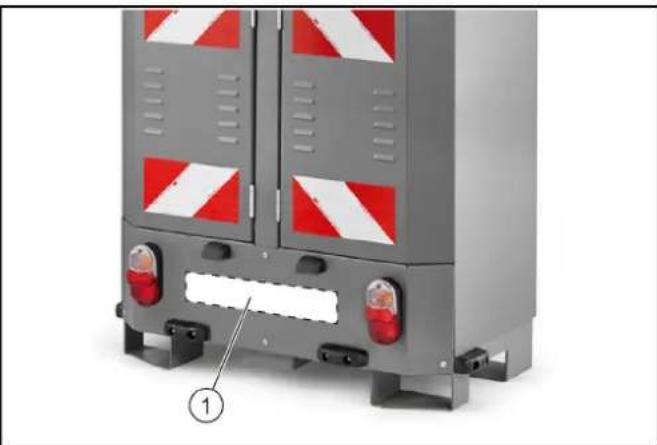
2 Warranty
In each country, the applicable warranty conditions are those published by our authorized distributor. Possible malfunctions of your device will be eliminated free of charge within the warranty period, provided they are due to material or manufacturing defects. In case of warranty claims, please contact your distributor or the nearest authorized customer service, presenting the proof of purchase.
(Address, see back page)
3 Intended use
This operating manual describes the device supplied with the WRS 200 attachment.
Depending on the model, the attachment can be mounted on the following vehicles.
MIC 35/42 MIC 50/70 MC130 MC250
The WRS 200 attachment is intended for removing dirt from vertical surfaces using a high-pressure water jet, with the appropriate high-pressure cleaning device.
This high-pressure cleaning device can also be used for cleaning hard-to-reach places.
The device may only be operated with the reversing valve to prevent backflow.
The WRS 200 attachment must only be used in accordance with its intended use, as described in this operating manual.
Parts of the intended use and maintenance of the prescribed technical inspection. The vehicle and its attachments may be used, maintained, and repaired only by persons who are familiar with this and have been informed of the associated risks.
The basic rules for safety and accident prevention, as determined by
the legislation, must be observed. Other important rules for technical safety, occupational health, and legislation regarding road traffic must also be observed.
The operating personnel must:
be physically and mentally fit - be instructed in the operation of the vehicle and its attachments - have read and understood the operating manual, as well as the operating manuals of the vehicle on which this attachment is mounted - have verified their ability to drive the vehicle before starting work - be designated by the company to drive the vehicle
Safety instructions
The following safety instructions apply to the device:
Observe the applicable national regulations and legislation for pressure equipment. Observe the applicable national regulations of the legislation for accident prevention. The pressure equipment must be checked regularly, and the results of the check must be recorded. - Note that the heating attachment is a high-pressure installation. The high-pressure installations must be checked regularly in accordance with the national requirements of the legislation. According to your national regulations, the initial commissioning of the device must be carried out by a qualified person. KARCHER has already carried out and documented this initial commissioning on your behalf. You will receive the documentation for this upon request from your KARCHER dealer. When requesting the documentation, please provide the serial number and the model number of the device. - Please note that according to your national regulations, the device must be regularly inspected by a qualified person. For this, please contact your KARCHER dealer. - The device and its accessories must not be modified in any way.
4.1 Battery
WARNING
Observe the safety instructions for charging, maintenance, and disposal of the battery in the operating manual of the vehicle. The battery poles must be covered with the protective cap.
4.2 Marking for work under high voltage
For work under high voltage, the following safety instructions apply:
- 13. No place the marking for operation under high pressure. The marking for operation under high pressure and the device for pressing must be checked for
compliance with the technical data of the maximum operating overpressure.
- Avoid contact with aggressive chemicals.
- Check the marking for operation under high pressure daily. Do not use damaged markings. If a leak is detected, do not use the marking for operation under high pressure. Do not use a marking for operation under high pressure with damaged threads.
- Place the marking for operation under high pressure so that it is not stepped on or does not create a risk of tripping for people. Do not use a marking that has been subjected to loading or stepping on it, bending, impact, or deformation that may cause damage. Store the marking for operation under high pressure so that it does not come into contact with mechanical parts.
4.3 Symbols on the device
Instruction
Replace worn or illegible symbols immediately.
1. Lock the lowering device with the pre-tensioning mechanism when not in use.
4.4.3 Water hammer arrester
The water hammer arrester (pressure surge) prevents the burner from being interrupted in the event of water shortage.
4.5 Degree of danger
DANGER
- Instruction for immediate danger that may lead to serious bodily injury or death.
- Warning about possible dangerous situation that could lead to minor or moderate injury.
DANGER
- Warning about possible dangerous situation that could lead to minor or moderate injury.
CAUTION
- Warning about possible dangerous situation that could lead to material damage.
4.6 Personal protective equipment
DANGER - When working with the device, keep hands away. Wear hearing protection if the operating instructions indicate sound pressure above 80 dB(A). See Technical
data from the operating instructions.
Wear suitable protective clothing and protective goggles to protect against splashes or spray. During use of the device under high pressure, aerosols may form. Inhalation of aerosols can lead to health damage.
The operator must carry out a risk assessment to determine the necessary protective measures against aerosols depending on the surface to be cleaned and the working environment. Respirators of class FFP 2 or higher are suitable for protection against water-based aerosols.
4.7 Safety instructions
DANGER: Danger of suffocation. Keep packaging film away from children. WARNING - Use the device only for its intended purpose. Follow local regulations and when working with the device, watch out for third parties, especially children. - The device is not intended for use by persons with reduced physical, sensory or mental capabilities, or lack of experience and/or knowledge. - The device must only be used by persons who have been trained to work with it or who have demonstrated their ability to service it, and for whom the use of the device is explicitly permitted. - Children must be supervised to ensure they do not play with the device. - Children and adolescents must not work with the device. DANGER: Protective devices serve for your protection. Never modify or bypass protective devices.
4.8 Electrical connection
WARNING: Do not operate the device if the high-pressure hose is damaged. Check the high-pressure hose for damage regularly. Only use original spare parts and accessories from the manufacturer. Warning
Damaged mains cable or connection cable must be replaced by the manufacturer.
ATTENTION: Read the operating instructions before commissioning the device. The device may only be operated with the approved accessories, which prevent backflow.
4.9 Electrical connection
DANGER: When using the device in risk zones (e.g., petrol stations), observe the relevant safety regulations. It is forbidden to operate the device in zones where there is a risk of explosion. Traffic routes/ventilation openings are dangerous for life.
Traffic routes/ventilation openings may be damaged by the high-pressure jet and may become detached. The sign on the road indicates this. When cleaning traffic routes/ventilation openings, keep a minimum distance of 30 cm.
WARNING: Do not use the device if there are people in the work area without appropriate protective clothing. When using the high-pressure hose, you may be injured by the high-pressure jet. Never use the high-pressure jet or the rotary nozzle with the high-pressure hose, which are longer than 75 cm. Due to the recoil of the high-pressure hose, a reactive force is generated. Due to the recoil, the high-pressure hose acts with a force directed backwards. Hold the spray lance and the high-pressure hose firmly. When using the recoil accessories for high-pressure cleaning, the reactive and retracting forces may increase. Do not direct the high-pressure jet at yourself, e.g., to clean objects or clothing. Do not direct the high-pressure jet at people, animals, live electrical equipment, or at the device itself. Before starting the device, close the shut-off valve. Do not spray over objects that pose a risk to health (e.g., asbestos). Before each use, check the device and accessories for proper condition and safe operation, e.g., the high-pressure hose, the spray lance, and the safety devices. Do not use the device if there are signs of damage. Immediately replace damaged components. Use only original spare parts from the manufacturer for the high-pressure hose, fittings, and couplings.
CAUTION: Never leave the device unattended while it is running. Do not open the cover while the engine is running. While working, do not kink the high-pressure hose. After working with hot water, let the markings cool down or work with the device for a short time with cold water. The device must stand on a stable, level surface. Before cleaning, you must carry out a risk assessment of the surface to be cleaned in order to determine the safety and health protection requirements. You must take the necessary protective measures.
ATTENTION: Do not work with the device at temperatures below 0°C. Perform cleaning of the engine only in a washing area with oil separators.
4.9.1 Working with cleaning agents
PPEI3NBOCT CbxpnaHaeuime noucmbaumepenapamHa Meema,HeoocmbnHu 3a deua. · Ppu ynompe6ama Ha noucmeau npenapamc b6nodaabaum uhoopmaouHHua ncm 3a 6e3onacnohMa Hnpou3bodumena Ha noucmeau m npenapamu,ocobeno yka3aHuraMa 3a nuHo 3auumHO obopydehae. · N3non3eaume caMo docmabehume un npenopbahuom npou3bodumena noucmeau npenapamu. H3non3baHemo Ha dpzuo noucmeau npenapamu unxumukanMoKe da enouu 6e3onacnocmma Ha ypeda. · Ppu nonadahe Ha noucmbau npenapamu b ouhme,behdaza 2u npomui me ochoBHO c boda u He3a6aHOn nompceme lekapcka nomouc,cbuO KaKMO npu no2nbuaHemo Ha
noucmeau npenapamu. Yka3aHue · Pa3npbckeaHemo Ha necmuu du e 3a6paHeno.
4.9.2 TopeIIka 3a ropeuca Boda
ONACHOCT - Onachocm om ekcnno3n nopadu Henodxodauo zoupu. 3apekaime cmo nocohomo 6 pkoobodcmeo 3a ekcnnoamaucur zoupu. - OmpaboteHume 2a3o8e ca ompo8Hu. He eduwaime ompaboteHu 2a3o8e. Ipu pa6oma Ha ypeda nomeueHua ocueypraume docmmbna behmulaqura u ombeXdahe ha ompaboteHume 2a3o8e. PPEyPExDEHNE Ppu 3apejdaHemocceyeepeme, ye bpxu opeu noBpXHocmu He nonada20pu8o. PPEIIA3JNBOCT - Onachocm om u3zapnHe. He ce Habejdaume had omeopa 3a ombexdahe Ha ompabotehu 2a0ee u He nocraume e Hezo. Ppu paBoma Ha zoepkama He dokocema HaapebamenHnK omen. Hukoza He zameaprme omeopu 3a ompexdane Ha ompabotehu 2a0ee. Yeepeme ce, ye 6bn3o do exodoe 3a b3dyx He ce omdeJe m emucuu Ha ompabotehu 2a0ee. Cna3eMayme yka3aHnma 3a 6e3oIacnohM Ha ypedu c deuzamen C bmpewho zopehe, daheHu epkoobcmo 3a ekcnnoamaua.
4.10 Prnka n noDpBxka
PPEyPExEHEH ●I3Knueaume ypea npedu noucmbaHe, nooppbkka u cMaHa ha yacmu Ha ypea. -Ppedu eKaBpu sabomu no ypea u npunadnexhocmume oc8obode me cucmema 3a bucoko hnaahe om hnaaHemo. PENPA3NBOCT · Bb3na2aume npueeKdaHemo e u3npaehocm cmo Ha o06peHu cepuu 3uHa cneuaunucmu ma3u obnacm, Koumo ca 3ano3HamuCecuku Cbp3au Hc moea npaeuna 3a 6e3oNaChocm. BHIMAHHE · Cb6nodaeaume npoepkama 3a 6e3onacnohmHa npenocumu ypeDu 3a npopecuoHaHa ynompeBa cbaNACHO eauDHume Ha Mcmomo npednucanua · Kcu cbedunehu unu dpyu nopeDu. He noucmeaйте ypeDa c bOdHa cmpy om Mapky unu nod eucoko hnaane. · He u3non3aйте Hmu aemOn u hepa3peDeHu KucenuHu, Humo pa3mBOpumenu, mbu kamo me amakybam u3non3aHume e ypea mamepuAnu.
4.11 Akcecoapn npe3epBnu actn
PPEIIA3JIHBOCT · N3non3aйте caMo akcecoapu u pe3epBu yacmu, Koumo ca odobpeHu om npou3oDumen. OpuzunHume akcecoapu u opuzunHume pe3epBu yacmu ocuaypraam 6e3onachama u 6e3npo6nemHa ekcnnoamaua Ha ypeDa.
Bbnaйте u3ebpuwaHemo Ha pemohmu MOhmaxa ha pe3epHu yacmu cmo Ha odobpeh cepu3, no mo3u hauH npedomspamreame onachocmu.
5 IperneIHa ypeDa WRS 200
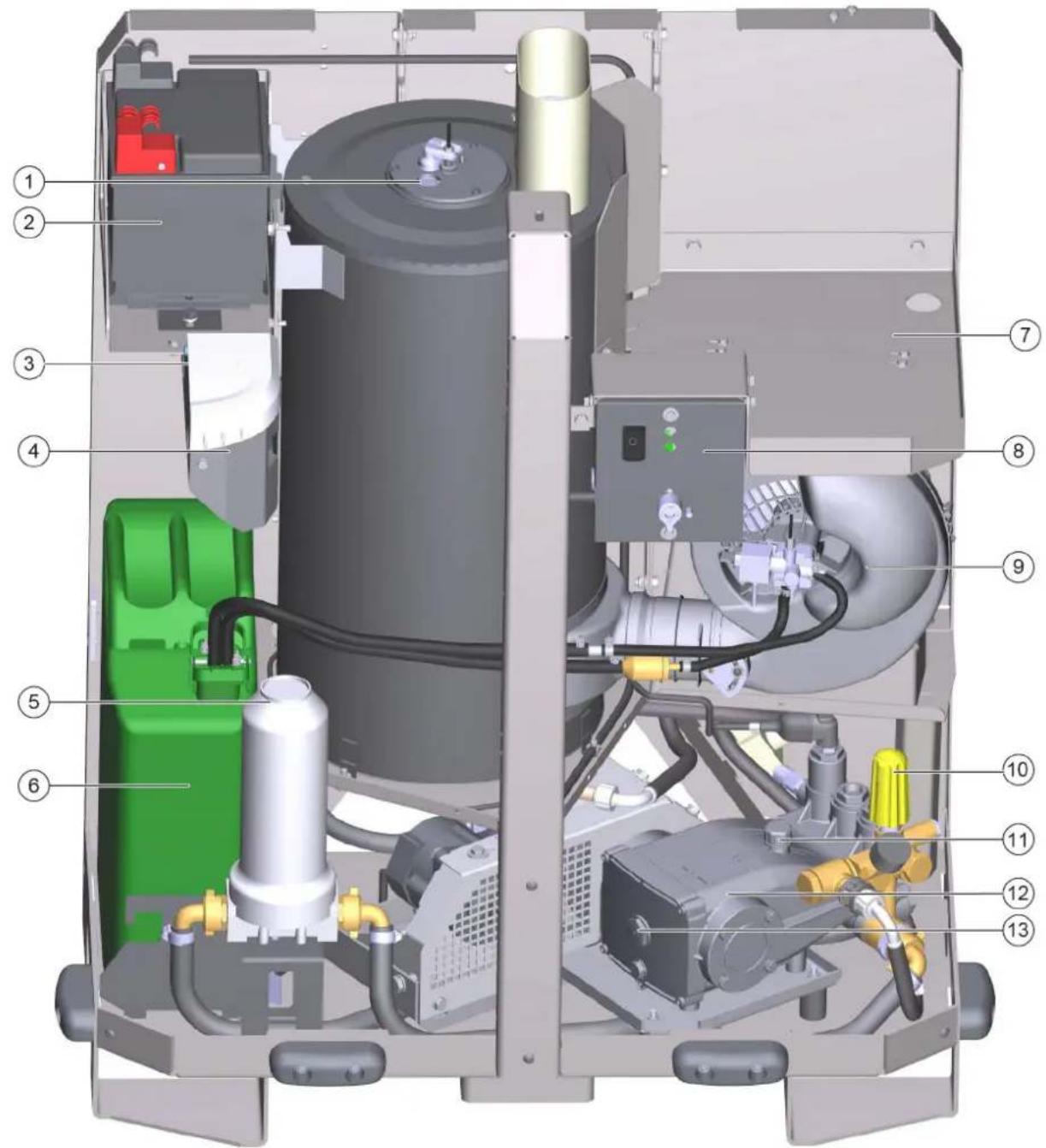
① Ha6nódaTeJHo CTbKNo Ha ropejkaTa 2AkyMaTOp ③Доэпашиnomma ④ NopdpbXka Ha cncTemata, pe3epBoap 3a RM 110 ⑥BoDENΦnITbP ⑥ Ty6a 3a ropuBO OTdeneHne 3a cbxpanHe Hn Mapkya 3pa6oTa nD BNCOKO HAJraHe ⑧Панелзаоблужвае BentnataopHa ropejikata 10 PerynupaHe Ha HanaRaHaTeO ⑪ OTbOp 3a nbJIHeHe Ha kanaka 12 NOMna 3a BnCOKo HaNraHe 13Ha6nIOaTeJIHO CTbKIO 3a HNBO Ha MaCNoTO
Yka3aHue
Warning: Before starting work, read the operating instructions and the safety instructions carefully, and observe the safety instructions.
6 Operating conditions WRS 200
Note
In case of damage or defects, please contact the Kärcher service center.
To use the WRS 200, a sufficiently large water reservoir is required. - The water reservoir must be securely fastened to the rear part of the vehicle. - When selecting the water reservoir, the permissible total weight and the permissible axle loads of the vehicle must be observed. According to the operating instructions, the rear edge must not protrude more than 400 mm beyond the contour of the vehicle. If the corresponding extensions (not permissible) are not mounted, this requirement is met.
-Platform C
The WRS 200 mounted on the rear part of the vehicle as a rear ballast must be mounted on the approved front ballast WR 100 Adv (accessory for increasing the front ballast), in accordance with the rear ballast.
- Platform E (MC 250)
CAUTION
Work with the WRS 200 is only permitted with the special frame (4.059-478.0).
Due to the maximum axle loads of the vehicle, the reservoir for fresh water of the vehicle cannot be used if the WRS mode is selected; the vehicle is unloaded and is driven necessarily through the openings of the tank. When working with the WRS 200, the reservoir for fresh water must remain open. In addition, when using the WR 100 Adv, due to the special loads in the front area, the extended weights cannot be used. The cover for the tank can be mounted or not, depending on the type of vehicle. The existing fastening elements must be used.
7 Mounting the vehicle adapter (platform C, D)
For the installation of the WRS 200, the adapter with the light strip is mounted on the rear part of the vehicle.
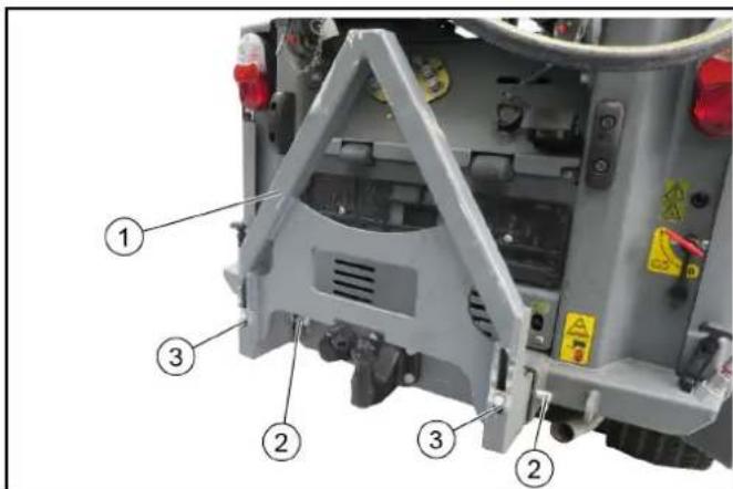
①Adapter with light strip
②Bolt with spring washer (2x)
③BonToBe(2x)
- Place the adapter in the support frame on the vehicle, following the position of the different vehicles.
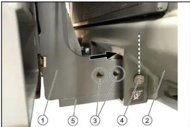
Figure: Attachment to MC 130, fixed with bolts and spring washers
①Adapter ② Support frame on the vehicle ③Position MIC 35/42 (platform C) ④Position MC 130 (platform D) ⑤Metal plate (2x) Note
Required for attachment to MC 130
- MIC 35/42: Place the adapter in position (1st or 2nd hole) and fix it from the front and back with bolts and spring washers. 3. MC 130: Attach the metal plate to the lower part of the adapter. Place the adapter as shown in the figure (3rd hole) and fix it from the front and back with bolts and spring washers.
- Tighten the bolts to fix the adapter without any play.
8 Mounting the adapter on the vehicle (platform E)
For the installation of the WRS 200 adapter with the light bar, it is mounted on the rear part of the vehicle.
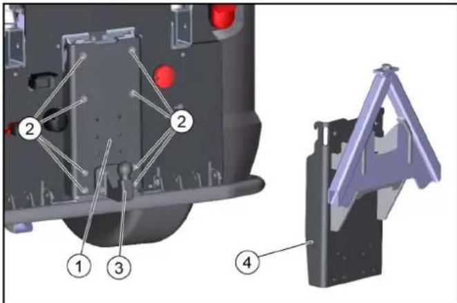
①Adapter plate ② M10x35 bolts and washers (8x) ③Removal kit (optional, depending on the type of registration certificate) ④Adapter plate with light bar
1. Remove the adapter plate with the removal kit from the vehicle (8 bolts and washers). 2. If necessary, attach the removal kit with M10x45 bolts, washers, and nuts (4x) to the adapter plate.
3. Similarly, place the adapter plate with the light bar on top and secure it with 8 bolts and washers.
9 Mounting the upper support
The upper support is used to stabilize the WRS 200 during operation and transport. It must be mounted once on the WRS 200.
MIC 35/42 (platform C) and MC 250 (platform E) are mounted through the ventilation openings.
The PnMC 130 nIIMIC 50/70 (platform D) installation is performed by the team. The following description shows the installation for platform D.
The mounting holes on the support are aligned.
Unless otherwise specified, tighten all screws and nuts with the standard torques.
The installation of the carrier vehicle is performed with 2 top connecting posts. The installation is described in one of the following chapters.
Components, top support
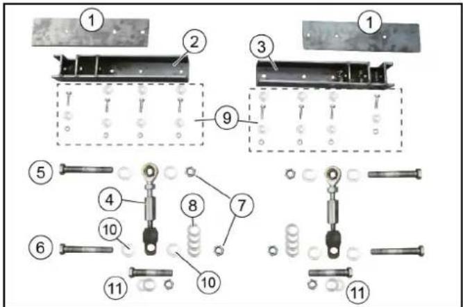
① Washer (2x)
② Holder
③ Top plate
④ Top connecting post (2x) bracket
For installation of the carrier vehicle
⑤ Bolt M16x120 (2x)
⑥ Bolt M16x100 (2x)
⑦ Self-locking nut M16 (4x)
⑧ Washer 18x200 (8x)
⑨ Fastening material, holder - bolts M8x30 (8x)
- Washers 8x200 (14x)
Bolts 16x200 (8x)
For mounting on the top connecting plate
- For mounting on the top connecting plate of platform D
1. Check the completeness of the delivery.
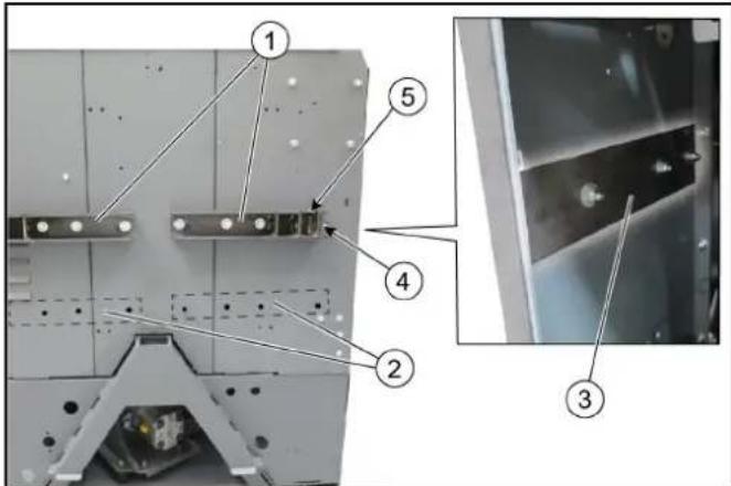
① Mounting of the top plate on platform D (MC 130, MIC 50/70) ② Mounting of the top plate on platform C (MIC 35/42) and platform E (MC 250) ③ Reinforcing plates above the boiler bolts
Mount the bolts without washers
⑤ Ignition of the top burner
- Mount the reinforcing plates on the top plate of WRS 200 (optional mounting depending on the platform). 3. USE BOLTS AND NUTS. On the side of the holder: Mount the bolts without washers.
- Mount the top plate according to the alignment.
10 Position of the top connecting plate
The top connecting plates must be properly secured depending on whether they are for form C, form D, or form E.
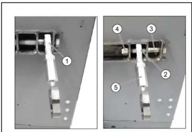
①Position for platform D ②Position for platform CIE ③Screw ④Self-locking nut ⑤Upper connecting bolt
1. Tighten the upper connecting bolts with the self-locking nuts in the appropriate position.
11. Mounting and connecting the WRS 200
The WRS 200 is attached to the alternator with the connecting bolt and is fixed with a screw. The device is additionally secured in the upper part to the bracket with the upper connecting bolts. It is recommended that a second person assists during mounting.
①WRS200 ②Lifting eye ③Alternator with connecting bolt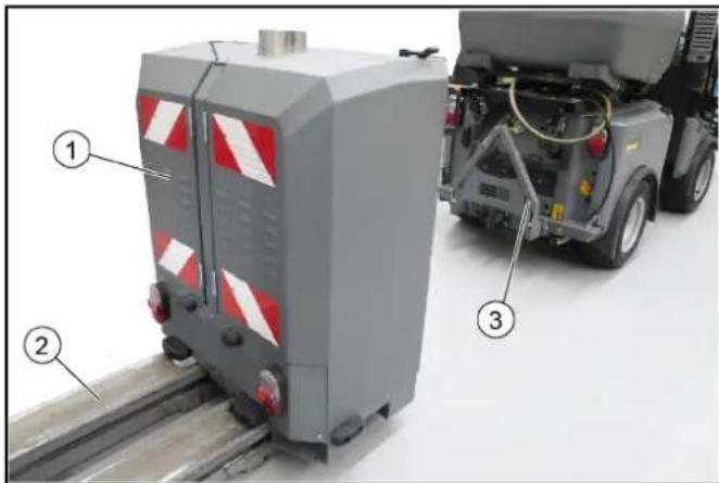
- Using the lifting eye, position the WRS 200 about 30 cm in front of the alternator and lower it until it rests on the alternator.
①Hydraulic hoses ②Water outlet ③Cable with plug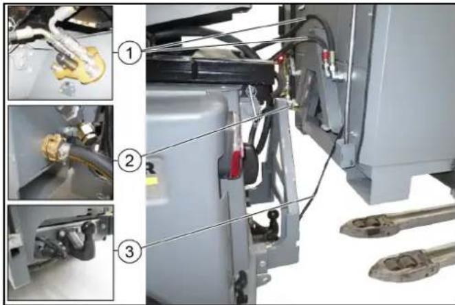
- Connect the water outlet.
- Connect the cable with plug to the contact of the remote control.
2. Connect the hydraulic hoses to the WRS 200 and insert them into the hydraulic outlet of the vehicle (follow the direction of flow and the colored rings, if any).
Screw (pre-tighten) ②WRS 200 5. Then push the WRS 200 device forward until it stops in the connecting bolt of the alternator. 6. Fix the WRS 200 with the screw. Tightening torque 80 Nm.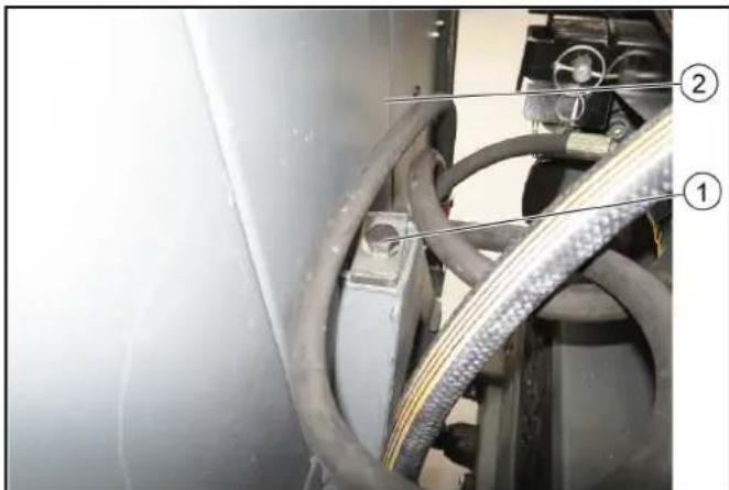
Figure: Securing the upper connecting bolt, platform C with ① adjusting nut, upper connecting bolt ② lock nut, securing bolt, securing bracket (platform C)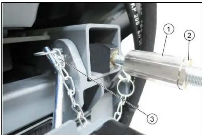
- Tighten the left and right upper connecting bolts of the vehicle.
Platform C: Secure to the vehicle with the supplied bolt and fix with the clamp (see figure).
Platform D and E: Secure to the vehicle with the screw, washer, and nut (included in the delivery kit) (see figure).
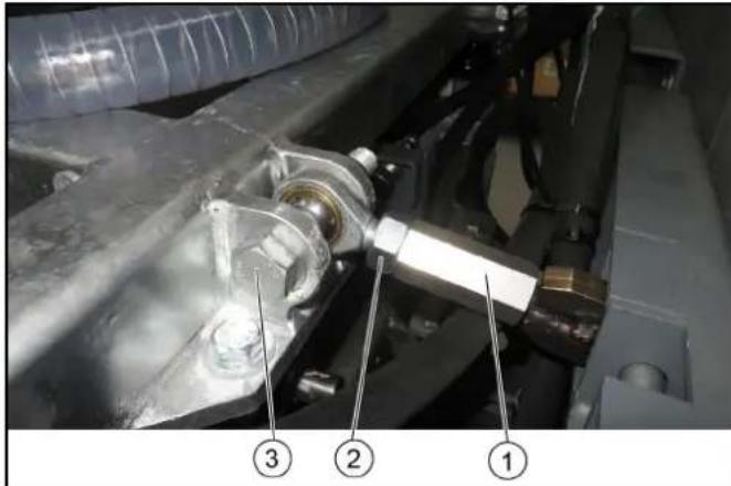
Figure: Securing the burner connection, platforms D and E
① Adjusting nut, burner connection ② Lock nut ③ Screw, washer, and nut (platforms D and E)
- Set the position of the WRS 200 with the adjusting nut and fix it with the lock nut.
12 Commissioning
WARNING
Danger of injury
Before using the device, check the battery, accessories, fuel lines, water hoses, and seals for perfect condition.
Do not use the device if its condition is not perfect.
1. Check the fuel level in the fuel tank, and refill if necessary. 2. Check the fluid level in the hydraulic reservoir, and top up with HM 110 if necessary. 3. Check the water level in the water reservoir, and top up if necessary. 4. Before using the public air intake, a filter must be installed (filter is supplied). The filter must be placed centrally in front of the rear lights at a distance of 40 mm.
12.1 Refueling
DANGER
Danger of explosion due to flammable fuel
When refueling, be careful that fuel does not spill onto hot parts or surfaces.
Danger due to electric shock and open flame.
Before charging, observe the safety instructions for use, as well as the instructions for open flame.
WARNING
Danger to health due to inhalation of vapors.
Do not charge in enclosed spaces.
ATTENTION
Setting the WRS 200:
- Thermostat at 0°C (extreme humidity limiter) - switch off the ventilator.
- Place the high-pressure nozzle on the hose.
- If necessary, activate the hose pressure regulator for spraying and the device for high pressure.
14.6 Working with the WRS 200
WARNING
Danger of injury due to reaction force.
Due to the water jet from the spray hose, a reaction force arises. When working, always hold the high-pressure spray gun and hose firmly.
1. Type of drive: mechanical. 2. Trigger for lowering and stopping work. 3. Adjust the pressure regulator. 1. For work under high pressure with a mechanical drive, set the lever to the rear position. 2. Press the trigger to lower and stop work. 3. The spray gun must be operated with the high-pressure hose, work properly. 4. If necessary, use the pressure regulator for the high-pressure hose to adjust the pressure for work under high pressure.
14.7 Working with the WR 10 accessory (optional)
WARNING
Danger from the spray gun nozzle
Set the pressure regulator to the minimum pressure for high pressure. Additionally, use the nozzle 2.114-004.0 (not included in the delivery set).
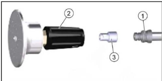
1. Nozzle
2. Spray gun head WR 10
3. Nozzle 2.114-004.0
Secure the nozzle between the tube and the spray gun head WR 10. - Start the pressure regulator for the high-pressure hose at minimum.
14.7.1 Storing the high-pressure work equipment and the spray gun
When working in dusty environments or when stopping work, store the spray gun with the spray gun and the high-pressure hose in the designated places.
14.8 Stopping work
- Stop the engine and let it cool down.
- Set the thermostat to 0°C and switch off the burner and the fan.
- Activate the high-pressure cleaning device in cold water mode until the high-pressure cleaning device, the high-pressure work indicator, and the high-pressure spray gun with the spray gun have cooled down (danger of burns). 4. Switch off the hydraulic system.
- Knob for draining.
- Close the water supply to the water reservoir.
- Press the trigger of the spray gun for high-pressure cleaning and release it to relieve the pressure in the system. 8. FIX THE TRIGGER WITH THE LOCKING MECHANISM.
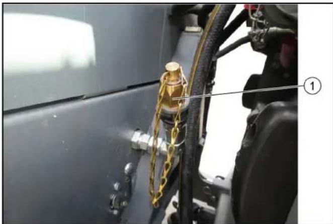
Close the accessory. 9. Remove the high-pressure hose from the high-pressure outlet of the WRS 200. To protect against freezing, drain the hose.
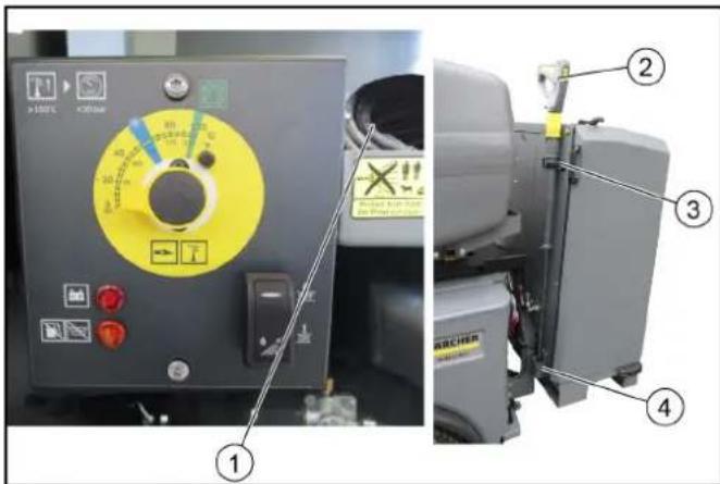
Storage location for the high-pressure hose ② Spray gun for high-pressure cleaning with hose for spraying ③ Rubber gasket for closing the mechanism ④ Supply
- Place the spray gun for high-pressure cleaning with the hose for spraying into the supply, and fix it with the rubber gasket and the mechanism of the supply. 11. Open the front door and place the high-pressure hose in the storage location.
15 Storage
△DANGER
Hazards and warnings
When storing, pay attention to the temperature of the device.
16 Maintenance and care
16.1 Maintenance interval
Note
To maintain the warranty claims, during the warranty period all service and maintenance work must be carried out by an authorized Karcher service center according to the inspection checklist.
Sound power level
U3MepeHo:96
TapaHTnpaHo: 99
IopnncBaunTe Nua DeeCTBaT OT IMeTo n KaTo nblHOMOuHnU Ha ynpaBntenHnO npA.
H. Jenner
Chairman of the Board of Management
S. Reiser
Director Regulatory Affairs & Certification
Пьномошник NO DOКум entaцета:
S. Reiser
Alfred Kärcher SE & Co. KG
Alfred-Karcher-Str. 28 - 40
71364 Winnenden (Germany)
Tei.: +49 7195 14-0
ΦaKc: +49 7195 14-2212
BunHeHdEn, 2018/09/01
Table of contents
Position MIC 35/42 (platform C)
14.6 Working with WRS 200
WARNING
Product: High-pressure washer
Type: 2 200-xxx
Relevant EU directives
2006/42/EU (+2009/127/EU)
2014/30/EU
2000/14/EU
ECER10
H. Jenner Chairman of the Board of Management
S. Reiser Director Regulatory Affairs & Certification
Documentation officer:
S. Reiser
Alfred Kärcher SE & Co. KG
Alfred-Karcher-Str.28-40
71364 Winnenden (Germany)
Tel: +49 7195 14-0
Winnenden, 2018/09/01
Table of contents
1 General information 387 2 Warranty 389 3 Intended use 389 4 Safety instructions 389 5 Overview of the WRS 200 device 392 6 Preliminary notes on using the WRS 200 ... 392 7 Attaching the adapter to the vehicle (C, D platform) 393 8 Attaching the adapter to the vehicle (E platform) 393 9 Installing the upper bracket 393 10 Positions of the upper towing eye 394 11 Installing and connecting the WRS 200 394 12 Before starting operation 395 13 Starting operation 397 14 Use 397 15 Storage 400 16 Care and maintenance 400 17 Troubleshooting 401 18 Technical data 402 19 EU Declaration of Conformity 402
1 General information
1.1 Description
△CAUTION
Material damage due to incorrect installation
Installation may only be carried out by a specialist qualified for this process.
Note
Also observe the operating instructions of the vehicle in which the additional device is being installed.
Keep the installation instructions for future use or for the next owner.
H. Jenner Chairman of the Board of Management
S. Reiser Director Regulatory Affairs & Certification
Documentation prepared by:
S. Reiser
Alfred Kärcher SE & Co. KG
Alfred-Karcher-Str. 28 - 40
71364 Winnenden (Germany)
Tel.: +49 7195 14-0
Fax: +49 7195 14-2212
Chairman of the Board of Management
Director Regulatory Affairs & Certification
1 General information
1.1 Description
Spare parts can be installed through proper installation.
Installation must be carried out by qualified personnel.
Qualified specialists.
Instructions
Follow the instructions for use of the transport vehicle on which this device is installed.
Keep these installation instructions for future use.
1.2 Environmental protection
Packaging materials can be recycled. Please dispose of packaging in an environmentally friendly manner.
Electrical and electronic devices contain valuable materials that can be recycled and components such as batteries, accumulators, and oils that, if handled or disposed of incorrectly, can pose a potential danger to human health and the environment. However, these components are necessary for the reliable operation of the device. Devices marked with this symbol must not be disposed of with household waste.
Instructions on components (REACH)
Current information on components can be found at: www.kaercher.com/REACH
1.3 Inspection of delivered equipment
Immediately report any transport damage to the dealer.
1.4 Scope of delivery
General safety regulations and accident prevention rules established by law.
It is necessary to comply with other standards regarding safety, industrial medicine, and traffic rules. The operating personnel must:
- be physically and mentally fit;
- be instructed on the operation of the machine and its equipment;
- before starting work, read and understand the operating instructions and the operating instructions of the vehicle on which the mounting kit is installed; confirm their ability to operate the machine; have instructions for operating the machine.
4 Safety instructions
The device is subject to the following safety rules:
When working with high-pressure equipment, comply with all national standards. Comply with national safety regulations in accordance with the law. It is necessary to regularly check the operation of high-pressure equipment and document the results of the check in writing. - Start up the device only in a properly installed condition. It is necessary to regularly check the device settings, complying with national legal regulations. In accordance with national regulations, in case of commercial use, the device must be put into operation by a qualified specialist. KARCHER specialists have already carried out the initial commissioning process and documented it. Documentation can be obtained by sending a request to the KARCHER partner company. When requesting documentation, please specify the device model and serial number. Please note that in accordance with national regulations, the device must be regularly inspected by qualified specialists. For this, strictly contact the KARCHER partner company. Any modification of the device is prohibited.
4.1 Battery
WARNING
Instructions on safety, charging, maintenance, and disposal of the battery are contained in the operating instructions of the vehicle.
Always keep the positive terminal of the battery covered with the protective cap.
4.2 High-pressure hose
The high-pressure hose is subject to the following safety rules:
Use only original high-pressure hoses. - The high-pressure hose must comply with the maximum working pressure specified in the technical characteristics. - Avoid contact with aggressive chemical substances. - Regularly check the high-pressure hose. Do not use kinked hoses. If external damage to the wires is visible, the high-pressure hose is no longer suitable for operation. Do not use a high-pressure hose with damaged connections. - Lay the high-pressure hose so that it is not driven over and no one trips over it. Do not use the hose if it has been crushed by a vehicle, as well as if it has been overstretched or kinked, even if no visible damage is present. Store the high-pressure hose so that no mechanical stress is applied.
4.3 Custom device
Insertion
If the inserted symbols are unreadable or lost, replace them.
| △HE6E3NEKA He6e3neka oniky ob zarayy novepknio Перед поамков робому damu mahuhi oxolohymu. | |
| △ПОЕРДЖECHNЯ He6e3neka mpaemvbaHnry iid cmpumehny bucokozomucky He cnpmoeyamu cmpyminb bucokozomucky ha liodeu, mbapun, ybeikheNeе eIekmpuuchne obladhannyчHa caMu npucmpiu. 3axuamu muOnu anapam bucokozomucky eid mopozy. | |
| ПОЕРДЖECHNЯ pro iHcTpyment, zuo obepTaetbcra | |
| He6e3nechna eIektpnUHa hapya! He knactn storpOnHi predmetn abo iHcTpymeHTn Ha akymyIaTOp. | |
| YBAFA He6e3neka ypaJenHnry opZanie cnUxy ПID quac poBOMu bukopucmoeyamu biDIOviDi 3acobu 3axucmy opZanie cnUxy. | |
| ПID quac po6OTn bVKopncToBvBatn BiDIOviDi 3axusChi okylarpi. | |
| ВИКOPINCTOBvBatn 3axusChi ryKabuCi |
4.4 Safety devices
Safety devices are intended to protect the user from unintentional activation or use for other purposes.
Follow the safety instructions given in the manual!
4.4.1 Pressure gauge switch
If the trigger is released, the high-pressure pistol's pressure gauge switch turns off the high-pressure pump, and the high-pressure flow stops.
Pressing the trigger again restarts the pump.
4.4.2 Safety lock of the high-pressure pistol
The safety lock on the high-pressure pistol blocks the trigger of the pistol.
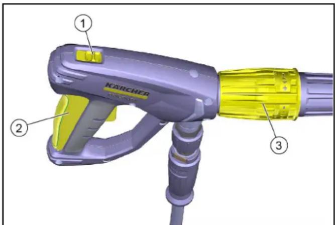
Safety lock
Position before: Trigger locked. Position after: Trigger not locked.
②Trigger
③Pressure regulator
- Do not use the tool until the release valve is locked with a locking device.
4.4.3 Locking system in case of water failure
The locking system in case of water failure (flow relay) shuts off the water supply in the event of a water failure.
4.5 Safety levels
DANGER
Indicates an imminent danger that directly threatens and can lead to serious or fatal injuries.
WARNING
Indicates a potentially dangerous situation that can lead to serious or fatal injuries.
CAUTION
Indicates a potentially dangerous situation that can cause minor or moderate injuries.
NOTICE
Indicates a potential dangerous situation that can cause material damage.
4.6 Personal protective equipment
CAUTION: Use appropriate protective gloves when using the device.
Use hearing protection as specified in the operating instructions.
Wear protective gloves and protective clothing according to the instructions for use. Use appropriate protective gloves and protective goggles to protect against splashes and spray. When using high-risk spray devices, aerosols may be formed. Inhalation of aerosols is harmful to health. The employer is obliged to conduct a risk assessment to determine the necessary measures to protect against aerosol inhalation based on the surface being treated and environmental conditions. Protective masks of class FFP 2 or higher are suitable for protection against aerosols.
4.7 General safety instructions
DANGER Danger of suffocation. Keep the packaging film out of the reach of children. WARNING Use the device only for its intended purpose. Consider the conditions of the workplace and pay attention to third parties, especially children, when working with the device. - The device is not intended for use by persons with reduced physical, sensory or mental capabilities, or by persons with insufficient experience and/or knowledge. - The device may only be used by persons who have read the instructions for handling it, are fully capable of operating it, and have been instructed in its use. - Supervise children to ensure they do not play with the device. - It is forbidden to work with the device without supervision. CAUTION Protective devices are intended for personal protection. It is forbidden to use protective devices for other purposes or to modify them.
4.8 Connecting the water supply
WARNING If the high-pressure hose is damaged, the device must not be put into operation. Damaged high-pressure hoses must be replaced immediately. Use only the hoses and connecting elements recommended by the manufacturer. The connection of all connecting hoses must be tight.
ATTENTION Observe the regulations established by the local water supply company. Connection to the drinking water network is only permitted with a suitable backflow preventer.
4.9 Operation
DANGER • When using the device in hazardous areas (e.g., at filling stations), observe the relevant safety regulations. - Operation in potentially explosive atmospheres is prohibited. - Damaged batteries or cables can pose a risk to health. Batteries or cables can be damaged by water jets under pressure and may catch fire. The first sign of damage is a change in color. When using batteries or cables, keep water jets at a distance of at least 30 cm. WARNING Do not use the device if people are within a radius of 0 m without protective equipment. In case of use with short
The high-pressure hose must be kept away from the hot engine. Do not use a nozzle with a high-pressure stream or a rotary nozzle with hoses shorter than 75 cm. The water jet coming out of the high-pressure hose creates a reaction force. When using the high-pressure hose, this force must be controlled. Hold the hose and the high-pressure hose firmly. When using rotary nozzles, the reaction force and torque may increase. Do not direct the water jet at yourself, for example, to clean clothes or shoes. Do not direct the water jet at people, animals, live electrical equipment, or the device itself. Before starting, close the water supply. Do not direct the water jet at objects containing substances hazardous to health (e.g., asbestos). Before each use, check the condition and operational safety of the device and additional equipment, such as high-pressure hoses, high-pressure nozzles, and safety devices. Do not use the device if it is damaged. Replace damaged components immediately. It is allowed to use high-pressure hoses, fittings, and connections recommended by the manufacturer.
WARNING: Do not leave the device unattended while it is operating. Do not open the housing while it is operating. Do not block the high-pressure nozzle while it is operating. When operating with cold water, do not leave the device running or switch it off for short periods. The device must be placed on a level and stable surface. Before starting work, a risk assessment must be carried out for the working area, taking into account safety and health protection measures. Based on the risk assessment results, necessary safety measures must be taken.
CAUTION: It is forbidden to operate the device at temperatures below 0°C. Cleaning must be carried out only in rooms equipped with an oil separator.
4.9.1 Operation of the detergent
WARNING: Store the detergent out of the reach of children. When using detergents, follow the safety instructions provided by the detergent manufacturer, especially regarding the use of personal protective equipment. Use only detergents recommended by the manufacturer. Using other detergents or chemicals may adversely affect the safety of the device. If detergent comes into contact with eyes, rinse thoroughly with water and consult a doctor, as well as if detergent is swallowed. The use of flammable detergents is prohibited.
4.9.2 Nozzle for hot water
DANGER: Danger of injury if using an unsuitable fuel. Fill the device only with the fuel specified in the operating instructions.
Exhaust gases are toxic. Do not inhale exhaust gases. During operation of the device, ensure adequate ventilation and removal of exhaust gases.
WARNING: Do not allow fuel to spill onto hot surfaces.
WARNING: Danger of burns. Do not lean over the opening of the fuel tank and do not put your hands into it. During operation, do not touch the fuel tank. It is forbidden to open the fuel tank cap. Make sure that there are no fuel leaks near the opening of the fuel tank. Follow the safety instructions for the device with an internal combustion engine, given in the operating instructions.
4.10 Cleaning and maintenance
WARNING: Before cleaning, maintenance, and replacing parts, turn off the device. Before carrying out any work with the device and accessories, remove the plug from the high-voltage system.
WARNING: Carry out repairs only through authorized service centers or specially trained personnel for this area, familiar with the relevant safety regulations.
ATTENTION: Follow the safety check instructions for checking electrical devices in accordance with local regulations. Short circuits or other damage. Do not clean the device under running water or under high pressure. Do not use solvents, undiluted acids, or solvents, as these substances damage the materials from which the device is made.
4.11 Accessories and spare parts
WARNING: Use only the accessories and spare parts that are approved for use by the manufacturer. Use original accessories and original spare parts; only they guarantee safe and trouble-free operation of the device. Using other accessories and spare parts may pose a risk of injury and damage to spare parts. Use only authorized service centers for repairs.
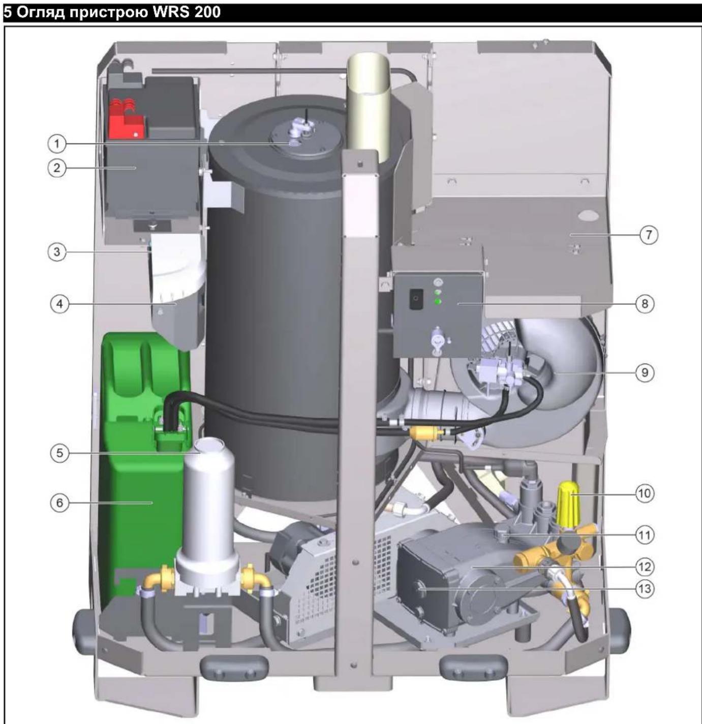
①Overview of the device ②Battery ③Suction pump ④Tank for cleaning agent ⑤Water filter ⑥Cartridge for the filter ⑦Screw for the high-pressure hose ⑧Control panel for the pressure regulator ⑨Filler cap ⑩High-pressure pump Overview of the device for checking the mat
Legend
Note: In the operating instructions, the terms "device" and "machine" are used synonymously.
In case of any questions, contact the service center of Karcher.
- For the WRS200, the tank must be provided with a sufficient volume. The tank must be securely fastened in the rear part of the vehicle. - When choosing the water tank, it is necessary to pay attention to the permissible total weight and the permissible axle load of the vehicle. According to the regulations, the tank must not protrude beyond the contour of the vehicle by more than 400 mm. If this is not observed (not allowed), the condition is not met. - Platform
The WRS 200 is installed in the rear of the vehicle, as a counterweight. The front beam WR 100 Adv (if available for this type of vehicle) or a suitable counterweight must be installed.
- Platform E (MC 250)
ATTENTION
Robot 3 WRS 200 is approved for use with the vehicle (4.059-478.0).
Due to the maximum load of the axle, the tank for the trailer and the semi-trailer cannot be used, it is automatically closed and forced to be emptied with the help of the software. The WRS mode is selected. The tank for the trailer and the semi-trailer remains closed during operation with WRS 200. In addition, in the case of using WR100 Adv, it is not possible to use additional equipment in the front part due to the axle load. According to the type of vehicle registration, the vehicle is equipped or not equipped with a towing device. Existing elements should be used.
7 Installation of the adapter on the vehicle (platform C, D)
The adapter with a triangular coupling is installed on the vehicle parts for mounting the WRS 200.
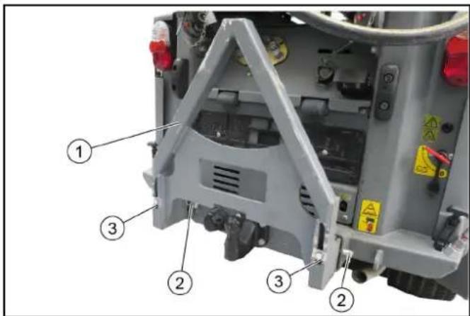
① Adapter with triangular coupling ② Bolt with spring washer (2 pcs.) ③ Screw (2 pcs.)
- Insert the adapter into the mounting frame of the machine, taking into account the position of different machines.
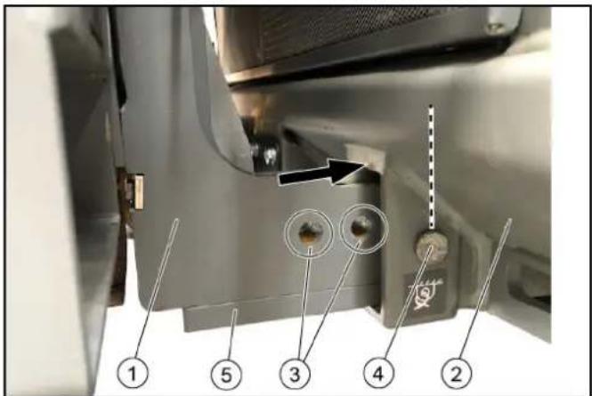
Figure: Installation of MC 130 is secured with bolts and spring washers
① Adapter
② Machine mounting frame ③ Position MC35/42 (platform C) ④ Position MC130 (platform D) ⑤ Metal plate (2x)
Instruction
Example of installation for MC 130
- MC 35/42: Insert the adapter into position (1st or 2nd hole) and secure the left and right bolts with spring washers. 3. MC 130: Secure the metal plate to the lower part of the adapter. Insert the adapter as shown in the figure (3rd hole) and secure the left and right bolts with spring washers.
- Tighten the screws to fix the adapter without play.
8 Installation of the adapter on the vehicle (platform E)
The adapter with a triangular coupling is installed on the vehicle parts for mounting the WRS 200.
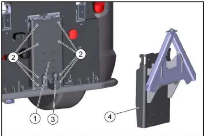
① Antenna plate ② Bolt M10x35 (8 pcs.) with lock washer (one set, depending on the type of registration) ④ Antenna plate with triangular hinge. 1. Attach the antenna plate with the lock washer device to the vehicle (8 bolts with washers).
2. Tighten the lock washer device (item 3) to the antenna plate using bolts M10x45, washers, and nuts (4 pcs.). 3. Hang the antenna plate with the triangular hinge in the same manner as indicated above, and tighten with bolts and washers.
9 Installation of the upper mounting
The upper mounting stabilizes the WRS 200 during operation and transportation. It must be installed on the WRS 200 once.
For MIC35/42 (platform C) and MIC250 (platform E), installation is done with ventilation openings.
For MIC 130 or MIC 50/70 (platform D), installation is done from above. Below is a description of the installation for platform D.
It is necessary to open the door D for installation of the mounting already in place. Unless otherwise specified, all bolts and nuts are to be tightened with the standard tightening torque.
Installation of the base machine is carried out with the help of 2 central rods. The installation process is described in one of the following chapters.
Installation of the upper mounting hinges
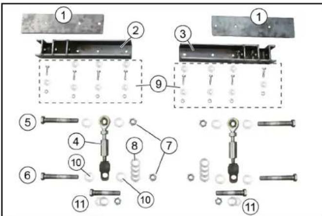
① Hinge plate (2 pcs.) ② Right hinge ③ Left hinge ④ Central rod (2 pcs.) Guide
For installation on the base machine
⑤ Bolt M16x120 (2 pcs.) ⑥ Bolt M16x100 (2 pcs.) ⑦ Lock nut M16 (4 pcs.) ⑧ Washer 18x200 (8 pcs.) ⑨ Hinge material
- Bolts M8x30 (8 pcs.) - Nuts M8 (8 pcs.) - Washers 8x200 (14 pcs.)
10 16x200 (8 pcs.) 11 Bolt, washer, nut - for installation of the central rod on platform D
1. Check the delivery set.
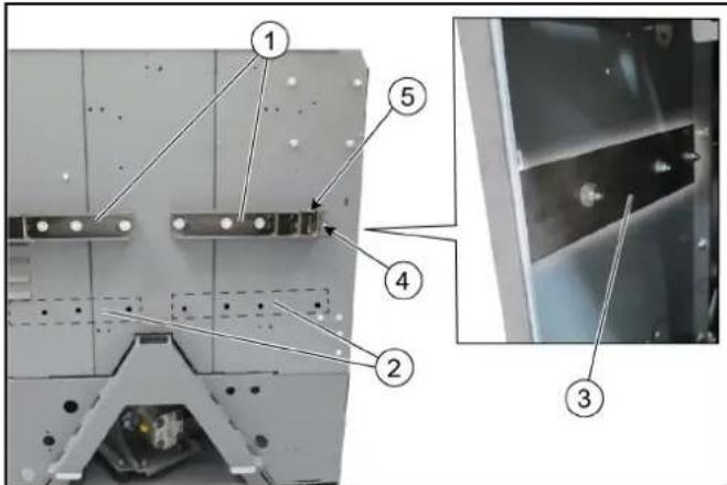
① Mounting the boom on platform D (MC 130, MIC 50/70) ② Mounting the boom on platform C (MIC 35/42) and platform E (MC 250) ③ Lower the plate
External screws
These screws are installed without washers
⑤ Second boom lift
2. Install the support plate for the WRS 200 boom (follow the installation procedure in the appendix). 3. Use screws with washers and nuts. On the boom side: install the external screws without washers. 4. Install the right boom in the same way.
10 Central holes
Depending on platform C, D, or E, the central holes must be aligned accordingly.
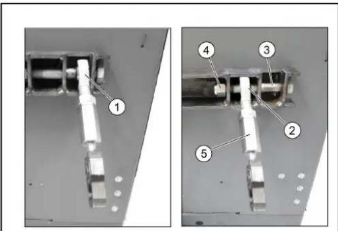
11 Installation and removal of WRS 200
The WRS 200 is attached to the adapter with a triangular connection and secured with a screw.
In addition, the second boom is attached to the transport vehicle with central holes.
It is recommended to perform the installation with two people.
①WRS 200 ②Lifting sling ③Adapter with triangular connection 1. Lift the WRS 200 with the lifting sling to a height of approx. 30 cm in front of the adapter and lift until it is above the adapter.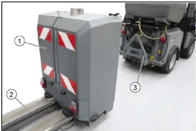
①Hydraulic hoses ②Pipe for water drainage ③Cable with plug 2. Connect the hydraulic hoses to the WRS 200 and insert them into the correct socket of the transport vehicle (follow the flow direction and color coding (if any)). 3. Connect the water hose. 4. Insert the cable with plug into the socket of the trailer.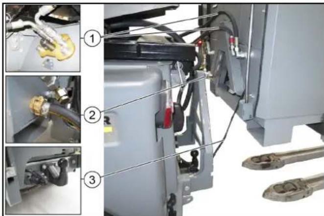
Setting the WRS 200:
- Turn the temperature regulator to 98 °C (green marking on the temperature regulator)
- Install the necessary attachments (nozzles) on the hose. If necessary, adjust the pressure on the jet hose or high-pressure pump.
14.5 High-pressure operation
Filling the transport vehicle:
- PTO 40 rpm: minimum number of revolutions per minute:
- MIC 35/42: 2250 rpm
- MIC 50/70: 2100 rpm
- MC 130: 2400 rpm
- MC 250: 1200 rpm
- Disconnect the contact switch (during work with standard equipment: high-pressure pistol and jet hose)
The procedure is determined depending on the transport vehicle and is described in the operating instructions for the transport vehicle.
Filling WRS 200:
- Set the temperature regulator to 0 °C (left turn). Close the shut-off valve. Install the high-pressure hose on the pipe.
- If necessary, adjust the pressure on the spray gun or on the high-pressure device.
14.6 Working with WRS 200
WARNING
Danger of injury from water jet
Water jet coming out of the spray gun creates a jet force. Keep high-pressure hose and spray gun under control during operation.
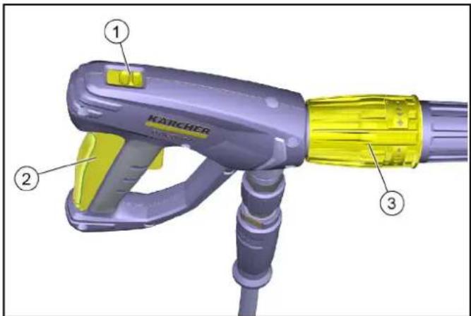
① Locking clip ② Trigger ③ Pressure regulator
- Lock the high-pressure gun with the locking clip, then release the trigger.
- Press the trigger and start the work. Direct the spray jet at the object to be cleaned, work thoroughly.
- If necessary: adjust the pressure on the spray gun or on the high-pressure device.
14.7 Working with accessory WR 10 (optional)
CAUTION
Danger of damage to the rotating nozzle. Set the pressure regulator on the high-pressure pump to the minimum value.
Also use nozzle 2.114-004.0 (not included in the delivery scope).
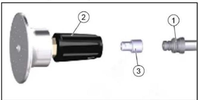
① Hose ② Rotating head WR 10 ③ Nozzle 2.114-004.0 Close the nozzle with the hose and the rotating head WR 10. - Set the pressure regulator on the high-pressure pump to the minimum value.
Before refilling or cleaning, keep the high-pressure spray gun away from the body and do not point it at people.
14.8 Shutdown
- 1. Turn off the transport device and do not switch it on again. 2. Set the temperature regulator to 0 °C and switch off the heating.
- Let the high-pressure device run for a while without water supply until the device, high-pressure hose, and high-pressure spray gun with spray lance have cooled down (risk of burns).
- Switch off the pressure control system.
- Switch off the device. 6. Close the water supply valve on the water tank.
- Press the trigger of the spray gun to release the pressure remaining in the system.
- Lock the trigger with the safety catch.
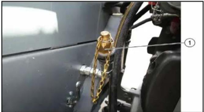
① Shut-off valve
- Unscrew the high-pressure hose from the high-pressure connection WRS 200. For protection against contamination, install the shut-off valve.
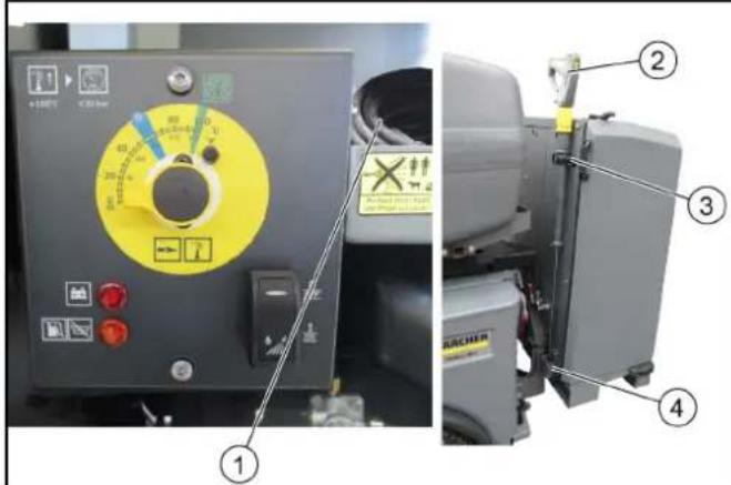
① Storage place for the high-pressure hose ② High-pressure spray gun with spray lance ③ Retaining clamp ④ Cover
10. Insert the high-pressure spray gun with spray lance into the holder and secure it with the retaining clamp. 11. Open the right door and place the high-pressure hose in the storage place.
Safety instructions for use
For storing the device, follow the instructions.
16 Maintenance and service
16.1 Maintenance intervals
Note
To maintain the warranty, all work on mechanical and preventive maintenance must be carried out within the warranty period
by the authorized service center of the Karcher company in accordance with the technical specifications.
16.2 Check/Clean the water filter
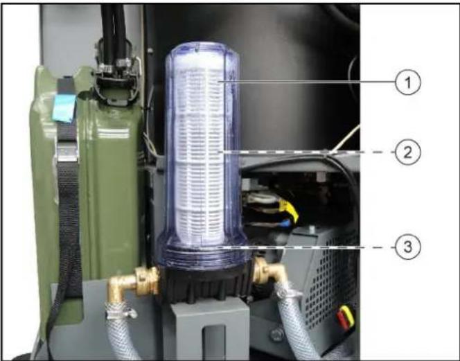
①Housing ②Water filter ③Seal
- Open the door.
- Check the water filter for contamination. To remove the water filter:
a. Turn off the water supply. b. Start the pump for a short time until the housing is empty. c. Remove and take off the housing.
d. Check and, if necessary, replace the seal. 4. Clean or, if necessary, replace the water filter. Apply silicone grease to the seal and the sealing surface of the water filter. 5. Install in reverse order. 6. Turn on the water supply.
16.3 Adding Oil to the High-Pressure Pump
SURFACE
Danger of injury!
Before adding oil, cool down the high-pressure pump.
CAUTION
Check the oil level on the cooled high-pressure pump.
Indicator
The correct level is at the center of the sight glass.
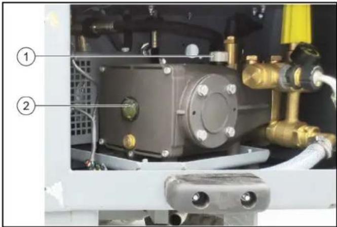
① Oil filler opening ② Sight glass
- Check the oil level through the sight glass, and if necessary, top up (to the center of the sight glass). Oil grade: 15W-40.
- Unscrew the cap from the oil filler opening.
- Add oil.
- Screw the cap back onto the oil filler opening.
- Wipe off any spilled oil.
17 Troubleshooting
Minor malfunctions can be eliminated independently using the following description.
In suction nozzles, only authorized service personnel may replace components.
SAFETY
Safety instructions
Before carrying out any work with the machine and maintenance, disconnect the base transport device.
SAFETY
Safety instructions for the operator
Before carrying out any work with the machine and maintenance, disconnect the battery plug.
ATTENTION
Repair work and work on electrical equipment must only be carried out by authorized service personnel.
Applied harmonized standards
EN 60335-1
EN 60335-2-79
EN 1829-1
EN 1829-2
EN ISO 12100:2010
EN 13309:2010
Manufacturer's declaration of conformity
2000/14/EC: Annex V
Sound power level
Measured: 96
Guaranteed: 99
Person authorized to compile the technical file and to manage the documentation.
H. Jenner Chairman of the Board of Management
S. Reiser Director Regulatory Affairs & Certification
Person responsible for the documentation:
S. Reiser
Alfred Karcher SE & Co. KG
Alfred-Karcher-Str. 28 - 40
71364 Winnenden (Germany)
Tel.: +49 7195 14-0
Fax: +49 7195 14-2212
M. BiHHHeHdEh, 01.09.2018

THANK YOU!
MERCI! DANKE! iGRACIAS!
Register your product and benefit from many advantages.
www.kaercher.com/welcome ★★★★★
Rate your product and tell us your opinion.
www.kaercher.com/dealersearch
Alfred Kärcher SE & Co. KG
Alfred-Karcher-Str. 28-40
71364 Winnenden (Germany)




- CONTENTS
- GENERAL
- DESCRIPTION
- CAUTION
- NOTE
- ENVIRONMENTAL PROTECTION
- NOTES ON THE CONTENT MATERIALS (REACH)
- CHECKING THE DELIVERY
- ACCESSORIES AND SPARE PARTS
- LICENCE PLATE
- WARRANTY
- INTENDED USE
- SAFETY INSTRUCTIONS
- BATTERY
- ATTENTION
- HIGH-PRESSURE HOSE
- SYMBOLS ON THE DEVICE
- SAFETY DEVICES
- ADHERE TO THE SAFETY INSTRUCTIONS IN THE CHAPTERS
- PRESSURE SWITCH
- HIGH-PRESSURE GUN SAFETY LATCH
- WATER SHORTAGE SAFEGUARD
- HAZARD LEVELS
- DANGER
- WARNING
- PROTECTIVE GEAR
- GENERAL SAFETY INSTRUCTIONS
- WATER CONNECTION
- OPERATION
- OPERATION WITH DETERGENT
- HOT WATER BURNER
- CARE AND SERVICE
- WRS 200 DEVICE OVERVIEW
- REQUIREMENTS FOR OPERATING THE WRS
- PLATFORM C AND D
- PLATFORM E (MC 250)
- ATTACH THE ADAPTER TO THE VEHICLE (PLATFORM C, D)
- FITTING THE ADAPTER TO THE VEHICLE (PLATFORM E)
- ATTACHING THE TOP MOUNT
- TOP MOUNT ATTACHMENTS
- UPPER LINK POSITION
- FITTING AND CONNECTING THE WRS
- PRE-COMMISSIONING
- ⚠ WARNING
- RISK OF INJURY
- REFUELLING
- EXPLOSION HAZARD DUE TO OVERFLOWING FUEL
- EXPLOSION HAZARD DUE TO SMOKING AND NAKED FLAMES
- HEALTH RISK FROM INHALED VAPOURS
- RISK OF DAMAGE DUE TO INCORRECT FUEL
- RISK OF DAMAGE DUE TO THE FUEL PUMP RUNNING DRY
- FILLING THE SYSTEM CARE CONTAINER
- HEALTH RISK
- ADJUSTING THE DOSAGE
- ④ POSITION
- STARTUP
- CONNECT THE HIGH-PRESSURE HOSE AND HIGH-PRESSURE GUN
- CONNECTING THE WATER HOSE
- PUMP RUNNING DRY
- RISK OF DAMAGE
- HIGH-PRESSURE CLEANER
- CONTROL PANEL
- ① BATTERY
- ② MINUS TERMINAL
- ELIMINATING WEEDS
- VEHICLE SETTINGS
- WRS 200 SETTINGS
- CLEANING WITH HIGH PRESSURE
- WORKING WITH THE WRS
- RISK OF INJURY DUE TO RECOIL FORCE
- WORKING WITH THE WR 10 ACCESSORY (OPTIONAL)
- RISK OF DAMAGE TO THE SPRAY HEAD
- HIGH-PRESSURE GUN AND SPRAY LANCE STORAGE
- FINISHING WORK
- STORAGE
- CARE AND MAINTENANCE
- MAINTENANCE INTERVALS
- CHECK/CLEAN THE WATER FILTER
- REFILLING OIL IN THE HIGH-PRESSURE PUMP
- TROUBLESHOOTING GUIDE
- RISK OF ELECTRIC SHOCK
- TECHNICAL DATA
- DEVICE PERFORMANCE DATA
- DIMENSIONS AND WEIGHTS
- OPERATING MATERIALS
- DETERMINED VALUES IN ACC. WITH EN
- EU DECLARATION OF CONFORMITY
- CURRENTLY APPLICABLE EU DIRECTIVES
- HARMONISED STANDARDS USED
- CONFORMITY EVALUATION PROCESS USED
- SOUND POWER LEVEL
- CONTENT
- INDEX
- TABLE OF CONTENTS
- REMOVING WEEDS
- DANGER OF BURNS
- DIMENSIONS AND WEIGHT
- SETTING THE DOSAGE
- HARMONIZED STANDARDS APPLIED
- APPLIED CONFORMITY ASSESSMENT PROCEDURE
- GENERAL INFORMATION
- MATERIAL DAMAGE DUE TO INCORRECT INSTALLATION
- DECLARATION ON INGREDIENTS (REACH)
- PROTECTIVE DEVICES
- TRIGGER GUARD FOR HIGH-PRESSURE WASHER
- DRY-RUN PROTECTION DEVICE
- DANGER LEVELS
- NOTICE
- PERSONAL PROTECTIVE EQUIPMENT
- OPERATING MODE WITH CLEANING AGENT
- MOUNTING PARTS OF THE UPPER FASTENING
- △CAUTION
- WORKING WITH WRS
- △WARNING
- RISK OF INJURY FROM REACTIVE FORCE
- RISK OF MATERIAL DAMAGE DUE TO INCORRECT INSTALLATION
- RELEVANT EU DIRECTIVES
- MATERIAL DAMAGE DUE TO INCORRECT MOUNTING
- APPLIED HARMONIZED STANDARDS
- △DANGER
- INSTRUCTIONS
- DECLARATION OF SUBSTANCES (REACH)
- NUMBER
- MARKING FOR WORK UNDER HIGH VOLTAGE
- INSTRUCTION
- WATER HAMMER ARRESTER
- DEGREE OF DANGER
- ELECTRICAL CONNECTION
- WORKING WITH CLEANING AGENTS
- TOPEIIKA 3A ROPEUCA BODA
- PRNKA N NODPBXKA
- AKCECOAPN NPE3EPBNU ACTN
- IPERNEIHA YPEDA WRS
- YKA3AHUE
- OPERATING CONDITIONS WRS
- WORK WITH THE WRS 200 IS ONLY PERMITTED WITH THE SPECIAL FRAME (4.059-478.0)
- MOUNTING THE VEHICLE ADAPTER (PLATFORM C, D)
- MOUNTING THE ADAPTER ON THE VEHICLE (PLATFORM E)
- MOUNTING THE UPPER SUPPORT
- COMPONENTS, TOP SUPPORT
- POSITION OF THE TOP CONNECTING PLATE
- MOUNTING AND CONNECTING THE WRS
- COMMISSIONING
- DANGER OF INJURY
- REFUELING
- SETTING THE WRS
- DANGER OF INJURY DUE TO REACTION FORCE
- DANGER FROM THE SPRAY GUN NOZZLE
- STORING THE HIGH-PRESSURE WORK EQUIPMENT AND THE SPRAY GUN
- STOPPING WORK
- MAINTENANCE AND CARE
- MAINTENANCE INTERVAL
- INSTRUCTIONS ON COMPONENTS (REACH)
- INSPECTION OF DELIVERED EQUIPMENT
- CUSTOM DEVICE
- INSERTION
- PRESSURE GAUGE SWITCH
- SAFETY LOCK OF THE HIGH-PRESSURE PISTOL
- LOCKING SYSTEM IN CASE OF WATER FAILURE
- SAFETY LEVELS
- CONNECTING THE WATER SUPPLY
- OPERATION OF THE DETERGENT
- NOZZLE FOR HOT WATER
- CLEANING AND MAINTENANCE
- LEGEND
- ROBOT 3 WRS 200 IS APPROVED FOR USE WITH THE VEHICLE (4.059-478.0)
- INSTALLATION OF THE ADAPTER ON THE VEHICLE (PLATFORM C, D)
- ① ADAPTER
- INSTALLATION OF THE ADAPTER ON THE VEHICLE (PLATFORM E)
- INSTALLATION OF THE UPPER MOUNTING
- INSTALLATION OF THE UPPER MOUNTING HINGES
- FOR INSTALLATION ON THE BASE MACHINE
- CHECK THE DELIVERY SET
- CENTRAL HOLES
- INSTALLATION AND REMOVAL OF WRS
- HIGH-PRESSURE OPERATION
- FILLING THE TRANSPORT VEHICLE
- FILLING WRS
- DANGER OF INJURY FROM WATER JET
- WORKING WITH ACCESSORY WR 10 (OPTIONAL)
- SHUTDOWN
- ① SHUT-OFF VALVE
- MAINTENANCE AND SERVICE
- ADDING OIL TO THE HIGH-PRESSURE PUMP
- SURFACE
- INDICATOR
- TROUBLESHOOTING
- SAFETY
- SAFETY INSTRUCTIONS FOR THE OPERATOR
- MANUFACTURER'S DECLARATION OF CONFORMITY
- THANK YOU
- MERCI! DANKE! IGRACIAS
Brand : Kärcher
Model : WRS 200
Category : Pest control