DPN90331XJ - Stapler DEWALT - Free user manual and instructions
Find the device manual for free DPN90331XJ DEWALT in PDF.
User questions about DPN90331XJ DEWALT
0 question about this device. Answer the ones you know or ask your own.
Ask a new question about this device
Download the instructions for your Stapler in PDF format for free! Find your manual DPN90331XJ - DEWALT and take your electronic device back in hand. On this page are published all the documents necessary for the use of your device. DPN90331XJ by DEWALT.
USER MANUAL DPN90331XJ DEWALT
English TOOL TECHNICAL DATA (original instructions) 6
natural_image
Close-up of a DPN9033-XJ nail marker with a hand adjusting its base (no visible text or symbols on the device itself)
natural_image
Close-up of a DPN9033SM-XJ high-voltage nail marker with a hand operating it (no visible text or symbols on the device itself)
natural_image
Close-up of a hand using a DPN10033-XJ power tool (no visible text or symbols on the device itself)
natural_image
Hand holding a DPWALY N1840 push-button presser (no text or symbols visible on the device body)
natural_image
Hand holding a DHWALT N/A connector with black metal base (no visible text or symbols)
text_image
DPN64C-XJ
natural_image
Hand operating a DPN75C-XJ printer with a handheld device (no visible text or symbols on the device itself)
natural_image
Black-and-white photo of a hand holding a DPN90C-XJ connector device (no visible text or symbols on the device itself)
natural_image
Close-up of hands using a sewing machine to adjust or install a component, labeled 'FIG 1 F' (no other text or symbols visible)
natural_image
Close-up of hands using a sewing machine to install a black hardener (no visible text or symbols)
natural_image
Close-up of hands operating a GEWALT Denny presser (no visible text or symbols)
natural_image
Close-up of mechanical components with an arrow pointing to a component, labeled 'FIG 4 FIG 6' (no other text or symbols visible)
text_image
FIG 5
natural_image
Close-up of a mechanical component with ribbed structure and mounting bracket (no visible text or symbols)
natural_image
Close-up of mechanical components with no visible text or symbols
natural_image
Close-up of hands using a tool to adjust or install a mechanical component (no visible text or symbols)
text_image
A B FIG 9FI
text_image
E C F D FIG 10
text_image
G B H FIG 11
text_image
FIG 12
natural_image
Close-up of a microscope with an arrow pointing to a component, no visible text or symbols
natural_image
Close-up of a white dewaterjet gun with a magnified inset showing a mechanical component (no text or symbols visible)
natural_image
Close-up of a mechanical device with a circular highlight on top (no visible text or symbols)ENGLISH
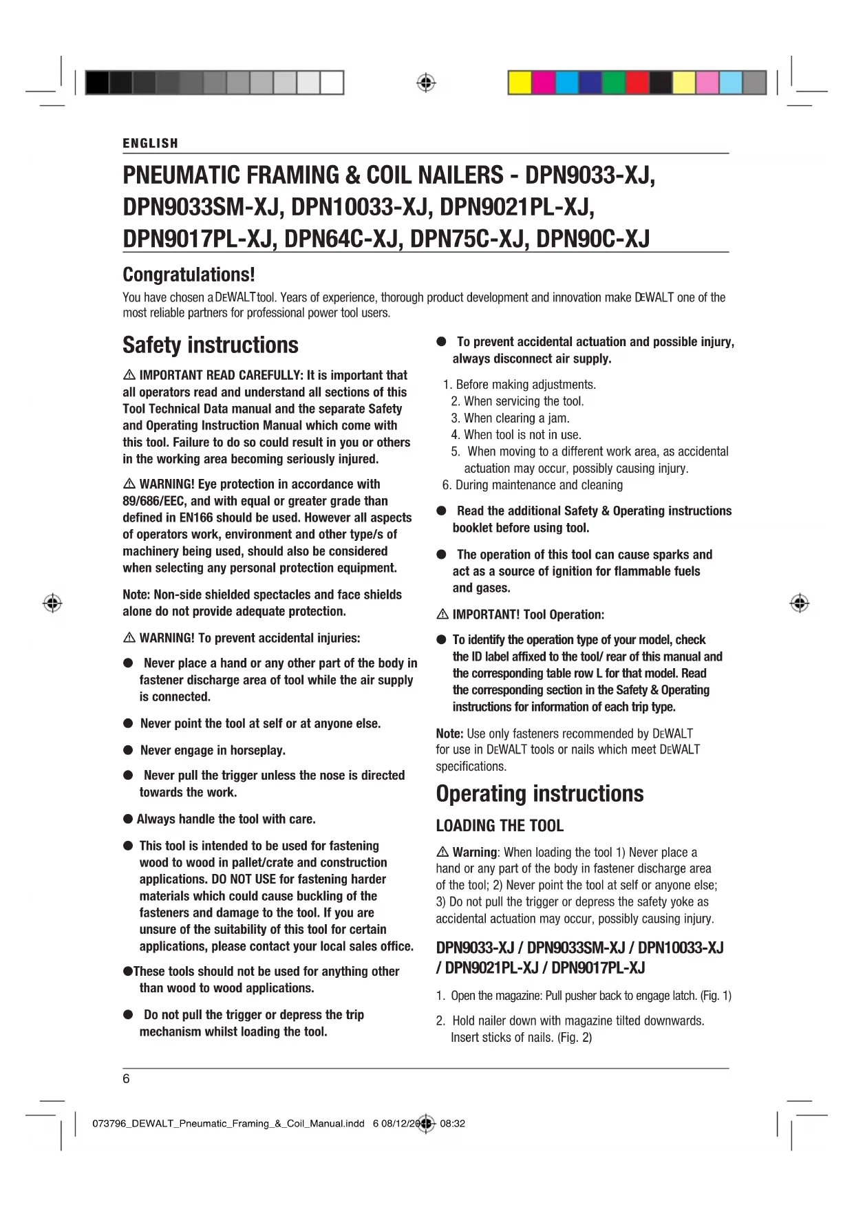
PNEUMATIC FRAMING & COIL NAILERS - DPN9033-XJ, DPN9033SM-XJ, DPN10033-XJ, DPN9021PL-XJ, DPN9017PL-XJ, DPN64C-XJ, DPN75C-XJ, DPN90C-XJ
Congratulations!
You have chosen a DEWALT tool. Years of experience, thorough product development and innovation make DEWALT one of the most reliable partners for professional power tool users.
Safety instructions
⚠️ IMPORTANT READ CAREFULLY: It is important that all operators read and understand all sections of this Tool Technical Data manual and the separate Safety and Operating Instruction Manual which come with this tool. Failure to do so could result in you or others in the working area becoming seriously injured.
⚠ WARNING! Eye protection in accordance with 89/686/EEC, and with equal or greater grade than defined in EN166 should be used. However all aspects of operators work, environment and other type/s of machinery being used, should also be considered when selecting any personal protection equipment.
Note: Non-side shielded spectacles and face shields alone do not provide adequate protection.
⚠ WARNING! To prevent accidental injuries:
● Never place a hand or any other part of the body in fastener discharge area of tool while the air supply is connected.
● Never point the tool at self or at anyone else.
● Never engage in horseplay.
● Never pull the trigger unless the nose is directed towards the work.
● Always handle the tool with care.
- This tool is intended to be used for fastening wood to wood in pallet/crate and construction applications. DO NOT USE for fastening harder materials which could cause buckling of the fasteners and damage to the tool. If you are unsure of the suitability of this tool for certain applications, please contact your local sales office.
●These tools should not be used for anything other than wood to wood applications.
- Do not pull the trigger or depress the trip mechanism whilst loading the tool.
● To prevent accidental actuation and possible injury, always disconnect air supply.
- Before making adjustments.
- When servicing the tool.
- When clearing a jam.
- When tool is not in use.
- When moving to a different work area, as accidental actuation may occur, possibly causing injury.
-
During maintenance and cleaning
-
Read the additional Safety & Operating instructions booklet before using tool.
● The operation of this tool can cause sparks and act as a source of ignition for flammable fuels and gases.
⚠️ IMPORTANT! Tool Operation:
- To identify the operation type of your model, check the ID label affixed to the tool/ rear of this manual and the corresponding table row L for that model. Read the corresponding section in the Safety & Operating instructions for information of each trip type.
Note: Use only fasteners recommended by DEWALT for use in DEWALT tools or nails which meet DEWALT specifications.
Operating instructions
LOADING THE TOOL
⚠ Warning: When loading the tool 1) Never place a hand or any part of the body in fastener discharge area of the tool; 2) Never point the tool at self or anyone else; 3) Do not pull the trigger or depress the safety yoke as accidental actuation may occur, possibly causing injury.
DPN9033-XJ / DPN9033SM-XJ / DPN10033-XJ / DPN9021PL-XJ / DPN9017PL-XJ
- Open the magazine: Pull pusher back to engage latch. (Fig. 1)
- Hold nailer down with magazine tilted downwards. Insert sticks of nails. (Fig. 2)
ENGLISH
- Close magazine: Release pusher by first pulling back on the pusher and then pressing the release tab. Slide pusher against the nails. (Fig. 3)
DPN64C-XJ / DPN75C-XJ / DPN90C-XJ
- Open the magazine: Pull down on the latch and swing the door open. Swing magazine cover open. (Fig. 4)
- Check adjustment: the nailer must be set for the length of nail to be used. Nails will not feed smoothly if the magazine is not correctly adjusted.
To change the setting:
The magazine contains an adjustable nail platform on which the nail coil rests.
The nail platform can be adjusted up and down to three or 4 nail settings. To change settings, pull up on the post and twist to the correct step. (Fig. 5)
| Step DPN64C-XJ DPN75C-XJ DPN90C-XJ | |
| 1 32-40mm 38-40mm 50-65mm | |
| 2 45-50mm 45-50mm 70-75mm | |
| 3 55-64mm 55-60mm 80-90mm | |
| 4 - 65-75mm - |
- Load the coil of nails: Place the coil of nails over the post in the magazine. Uncoil enough nails to reach the feed pawl. Place the first nail in front of the front tooth on the feed pawl, in the driver channel. The nail heads must be in the slot in the nose. (Fig. 6)
- Swing the door/magazine cover closed. Check that the latch engages when released. (If it does not engage, check that the nail heads are in the slot in the nose.)
NOTE: DPN64C-XJ / DPN75C-XJ ONLY
Removal of plastic strip: As nails are driven, the plastic strip will feed out of the tool. When sufficient strip has been fed out, it can be torn away by pulling against the tear edge in the nose. (Fig. 7)
REMOVING NAILS
(DPN9033-XJ / DPN9033SM-XJ / DPN10033-XJ / DPN9021PL-XJ / DPN9017PL-XJ)
- Disconnect the tool from the air supply
- Pull pusher back until it is securely engaged (Fig. 8)
- Slide nails back to opening and push out
CAUTION: The pusher and pusher spring (constant force spring).
Caution must be used when removing nails, as if pusher is disengaged from latch it could spring forward potentially pinching your hand.
Extra caution should be taken when carrying out maintenance on the magazine area of the tool. The spring is wrapped around but not attached to a roller. If the spring is stretched beyond its length, the end will come off the roller and the spring will roll up with a snap, with a chance of pinching your hand. Also the edges of the spring are very thin and could cut your hand. Care must also be taken to insure no permanent kinks are put in the springs as this will reduce the springs force.
GUIDE ROD INSTALLATION AND REMOVAL (DPN9033-XJ / DPN9033SM-XJ / DPN9021PL-XJ / DPN9017PL-XJ)
Step 1 (Fig. 9): Locate guide (A); Pull and rotate cover (B).
Step 2 (Fig. 10): Locate access windows for installation and removal of guide rod (C); Locate guide rod storage channel (D); Rotate cover open to install or remove guide rod (E); Install or remove guide rod through rear of magazine (F).
Step 3 (Fig. 11): Install guide rod through (G) for 2.8mm to 3.3mm shank nails. Rotate cover (B) to close; Install guide rod through (H) for 3.3mm to 4.1mm shank nails. Rotate cover (B) to close.
FASTENER DEPTH CONTROL ADJUSTMENT (DPN9033-XJ / DPN9033SM-XJ / DPN9021PL-XJ / DPN9017PL-XJ / DPN90C-XJ) (FIG. 12)
The Fastener Depth Control Adjustment feature provides control of the nail drive depth from flush with or just above the work surface to shallow or deep countersink.
Warning! Disconnect tool from air supply before attempting any parts disassembly and before changing the work contacting element adjustment.
- Push in Locking Button
- Adjust contact arm up to increase depth of drive or down to decrease it.
- Release locking button.
ENGLISH
DPN10033-XJ / DPN64C-XJ / DPN75C-XJ
(Fig. 13)
The DIAL-A-DEPTH™ Fastener Control adjustment feature provides close control of the fastener drive depth; from flush with the work surface to shallow or deep countersink.
First, set the air pressure for consistent drive in the specific work, then use the DIAL-A-DEPTH™ Fastener Control adjustment to give the desired depth of drive.
UTILITY HOOK (Fig. 14)
These tools may include an additional utility hook suitable for storage and temporary hanging of the tool.
⚠ WARNING! Never use the utility hook to hang the tool from the body, clothing or belt.
⚠ WARNING! Never use the utility hook with contact (black) trigger actuated tools.
DIRECTIONAL EXHAUST DEFLECTOR (FIG. 15 - ALL MODELS)
The adjustable exhaust deflector can be rotated into any desired position by hand without the use of tools.
FRANÇAIS
CLOUEUSES A CHARPENTE ET A ROULEAUX PNEUMATIQUES - DPN9033-XJ, DPN9033SM-XJ, DPN9021PL-XJ, DPN9017PL-XJ, DPN64C-XJ, DPN75C-XJ, DPN90C-XJ
Félicitations !
| Cran DPN64C-XJ DPN75C-XJ DPN90C-XJ | |
| 1 32-40mm 38-40mm 50-65mm | |
| 2 45-50mm 45-50mm 70-75mm | |
| 3 55-64mm 55-60mm 80-90mm | |
| 4 - 65-75mm - |
| Schritt DPN64C-XJ DPN75C-XJ DPN90C-XJ | ||
| 1 32-40mm 38-40mm 50-65mm | ||
| 2 45-50mm 45-50mm 70-75mm | ||
| 3 55-64mm 55-60mm 80-90mm | ||
| 4 - 65-75mm - |
| Stap DPN64C-XJ DPN75C | XJ DPN90C-XJ | |
| 1 32-40mm 38-40mm | 50-65mm | |
| 2 45-50mm 45-50mm | 70-75mm | |
| 3 55-64mm 55-60mm | 80-90mm | |
| 4 - 65-75mm - |
| Trin DPN64C-XJ DPN75C-XJ DPN90C-XJ | |
| 1 32-40mm 38-40mm 50-65mm | |
| 2 45-50mm 45-50mm 70-75mm | |
| 3 55-64mm 55-60mm 80-90mm | |
| 4 - 65-75mm - |
| Vaihe DPN64C-XJ DPN75C-XJ DPN90C-XJ | |
| 1 32-40mm 38-40mm 50-65mm | |
| 2 45-50mm 45-50mm 70-75mm | |
| 3 55-64mm 55-60mm 80-90mm | |
| 4 - 65-75mm - |
| Βήμα | DPN64C-XJ DPN75C-XJ DPN90C-XJ | ||
| 1 32-40mm 38-40mm 50-65mm | |||
| 2 45-50mm 45-50mm 70-75mm | |||
| 3 55-64mm 55-60mm 80-90mm | |||
| 4 - 65-75mm - | |||
| Passo DPN64C-XJ DPN75C-XJ DPN90C-XJ | |
| 1 32-40mm 38-40mm 50-65mm | |
| 2 45-50mm 45-50mm 70-75mm | |
| 3 55-64mm 55-60mm 80-90mm | |
| 4 - 65-75mm - |
| Trinn DPN64C-XJ DPN75C-XJ DPN90C-XJ | |
| 1 32-40mm 38-40mm 50-65mm | |
| 2 45-50mm 45-50mm 70-75mm | |
| 3 55-64mm 55-60mm 80-90mm | |
| 4 - 65-75mm - |
| Passo DPN64C-XJ DPN75C-XJ DPN90C-XJ | |
| 1 32-40mm 38-40mm 50-65mm | |
| 2 45-50mm 45-50mm 70-75mm | |
| 3 55-64mm 55-60mm 80-90mm | |
| 4 - 65-75mm - |
| Paso DP | N64C-XJ DPN75C | XJ DPN90C-XJ | |
| 1 32-40mm | 38-40mm | 50-65mm | |
| 2 45-50mm | 45-50mm | 70-75mm | |
| 3 55-64mm | 55-60mm | 80-90mm | |
| 4 - 65 | -75mm - |
| Steg DPN64C-XJ DPN75C | XJ DPN90C-XJ | |
| 1 32-40mm 38-40mm | 50-65mm | |
| 2 45-50mm 45-50mm | 70-75mm | |
| 3 55-64mm 55-60mm | 80-90mm | |
| 4 - 65-75mm - |
| Krok DPN64C-XJ DPN75C-XJ DPN90C-XJ | |
| 1 32-40mm 38-40mm 50-65mm | |
| 2 45-50mm 45-50mm 70-75mm | |
| 3 55-64mm 55-60mm 80-90mm | |
| 4 - 65-75mm - |
| Krok DPN64C-XJ DPN75C-XJ DPN90C-XJ | |
| 1 32-40mm 38-40mm 50-65mm | |
| 2 45-50mm 45-50mm 70-75mm | |
| 3 55-64mm 55-60mm 80-90mm | |
| 4 - 65-75mm - |
| Lépés DPN64C-XJ DPN75C-XJ DPN90C-XJ | |
| 1 32-40mm 38-40mm 50-65mm | |
| 2 45-50mm 45-50mm 70-75mm | |
| 3 55-64mm 55-60mm 80-90mm | |
| 4 - 65-75mm - |
| treaptă DPN64C-XJ DPN75C-XJ DPN90C-XJ | |
| 1 32-40mm 38-40mm 50-65mm | |
| 2 45-50mm 45-50mm 70-75mm | |
| 3 55-64mm 55-60mm 80-90mm | |
| 4 - 65-75mm - |
GB CE DECLARATION OF CONFORMITY
We declare under our sole responsibility that this fastener driving tool as identified above is in conformity with the following standards: EN 792-13:2000+A1:2008 in accordance with regulations 2006/42/EC. Technical construction files for use by authorities are available from the addresses below.