DDF5120550 - Stapler DEWALT - Free user manual and instructions
Find the device manual for free DDF5120550 DEWALT in PDF.

| Type de produit | Cloueur à gaz (agrafeuse) |
| Marque et modèle | DEWALT DDF5120550 |
| Dimensions (H × L × P) | 365 mm × 124 mm × 334 mm |
| Poids (avec batterie et cartouche de gaz) | 3,6 kg |
| Batterie | 6 V DC, 1.5 Ah, NiMH (ref. DDF5610500) |
| Chargeur | 100-240 V AC, 50/60 Hz, output 8 V DC, 1.5 Ah (ref. DDF5610520) |
| Cartouche de gaz | DEWALT (ref. DDF5140500) |
| Agrafes/clous autorisés | Length 15-40 mm, diameter 2.6/3.0/3.7 mm, flat or round head Ø 6.4 mm |
| Capacité du chargeur | 22 nails |
| Puissance d'impact | 105 J |
| Durée de charge | 2.5 hours (empty battery) |
| Niveaux sonores | LWA = 107.0 dB ; LpA = 99.3 dB ; LpCpeak = 131.5 dB |
| Vibrations | 18.5 m/s² (K = 1.6 m/s²) |
| Plage de température d'utilisation | -10 °C to 40 °C |
| Mode veille | Yes (after 24 h of inactivity) |
| Entretien | Clean air filter with compressed air; do not oil or grease; service at authorized workshop |
| Sécurité | Contact trigger, safety lock, battery switch, protection against accidental firing |
| Accessoires fournis | Carrying case, charger, two batteries, hanging hook |
| Garantie constructeur | 1 year (parts and labor) |
Frequently Asked Questions - DDF5120550 DEWALT
User questions about DDF5120550 DEWALT
0 question about this device. Answer the ones you know or ask your own.
Ask a new question about this device
Download the instructions for your Stapler in PDF format for free! Find your manual DDF5120550 - DEWALT and take your electronic device back in hand. On this page are published all the documents necessary for the use of your device. DDF5120550 by DEWALT.
USER MANUAL DDF5120550 DEWALT
natural_image
Illustration of a 5-wheeled NDA8818888888888888888888888888888888888888888888888888888888888888888888888888888888888888888888888888888 (no text or symbols visible on the device body)DDF5110500
DDF5120550
English (Translation of the original instructions) 35
natural_image
Illustration showing two workers handling a baby on a conveyor belt, with a 90-degree angle indicator below (no text or symbols on the figures)Personbeskyttelse:
natural_image
Technical line drawing of a mechanical assembly with bolts and brackets (no text or symbols)2.6 Tilbehør
Tilbehør Art.nr.
natural_image
Line drawing of a hand using a tool to adjust or install a mechanical component, with no visible text or symbols.natural_image
Line drawing of a hand adjusting a mechanical component with an arrow indicating the process (no text or symbols present)natural_image
Line drawing of a handheld device with a curved arrow indicating rotation or movement (no text or symbols)natural_image
Line drawing of a firearm with ammunition being inserted, showing stock position (no text or symbols)natural_image
Line drawing of a hand holding a firearm with an arrow indicating the grip (no text or symbols present)4 Betjening
Affyring af søm:
natural_image
Line drawing of a hand using a tool to adjust or install a mechanical component (no text or symbols visible)natural_image
Line drawing of a hand adjusting a mechanical component with a curved arrow indicating rotation (no text or symbols)natural_image
Illustration showing two workers at a table and a 90-degree angle indicator (no text or symbols)natural_image
Technical line drawing of a mechanical assembly with bolts and brackets (no text or symbols)2.6 Zubehör
Zubehör Art.Nr.
natural_image
Line drawing of a hand using a tool to adjust or install a mechanical component, with no visible text or symbols.Akku laden:
natural_image
Illustration of a hand holding a cylindrical mechanical component with an arrow indicating assembly or adjustment (no text or symbols present)natural_image
Line drawing of a handheld device with a black arrow indicating rotation or movement (no text or symbols)natural_image
Line drawing of a firearm with ammunition being inserted (no text or symbols)natural_image
Line drawing of a hand holding a firearm with a knife inserted (no text or symbols)4 Betrieb
Nägel eintreiben:
natural_image
Line drawing of a hand operating a mechanical device with arrows indicating motion or force direction (no text or symbols present)natural_image
Line drawing of a hand using a tool to adjust or install a mechanical component, with no visible text or symbols.Vice President HTF Construction and DIY Europe
D-65510, Idstein, Germany
Trak-It® C5 GAS ACTUATED NAILER DDF5110500, DDF5120550
Table of Contents
1 Safety Notes 36
1.1 Intended Use 36
1.2 Safety Labels on the Devices 36
1.3 Warnings in this Manual ....37
1.4 Protective Equipment 37
1.5 Device and Operational Safety 37
1.6 Gas Cartridge....39
1.7 Charger and Battery 39
1.8 Disposal 39
2 Unit/Device Overview....40
2.1 Scope of Delivery ....40
2.2 Individual Parts and Designations ....40
2.3 Sleep Mode 40
2.4 LED Device Indicator ....40
2.5 Hanging Hook 40
2.6 Accessories....41
3 Before using the Device ....41
3.1 Charging the battery ....41
3.2 Inserting the Gas Cartridge 42
3.3 Inserting the Nail Strip 43
4 Operation....43
4.1 Using the Gas Nailer 43
4.2 Removing the Nail Strip 44
4.3 Removing stuck Nails ....45
5 Cleaning and Maintenance ....46
5.1 Cleaning the Air Filter 46
5.2 Cleaning the Surfaces ....46
5.3 Maintaining the Gas Nailer ....46
6 Technical Data 47
6.1 Gas Nailer 47
6.2 Permissible Nails and Gas Cartridges ....47
7 Troubleshooting 47
8 Manufacturer Warranty 49
9 Declaration of Conformity....49
1 Safety Notes

Please read the safety information carefully in order to ensure a safe and proper operation of the device. Retain the operating instructions until the product is disposed of.
1.1 Intended Use
The Gas Nailer has to be used in accordance with the specifications of this instruction manual. Gas Nailers are not „toys“ and require prudent, responsible and careful handling. The Gas Nailer may only be used by persons over the age of 18 or trainees over the age of 16 in the presence of a responsible supervisor. They must not be under the influence of fatigue, alcohol, medication or drugs.
Suitable materials to use as a base, for example
– Concrete of normal strength
- S t e e l
Materials that are unsuitable and should not be used as a base, for example:
– Materials that are too soft or too thin
– Materials that are too brittle, such as glass or ceramic
– Materials that are too hard, such as hardened steel
– Hollow block masonry
– Cast iron, plastic, marble, gypsum plasterboards
Misapplications, misuse or „fooling around“ may cause lethal injuries and serious property damage. This particularly includes
– The overriding of safety mechanisms
- Misusing the device as a „fi rearm“
– Misusing the device as a hammer or similar tool
Only use those gas cartridges, charging devices and batteries made by the manufacturer of the Gas Nailer and only use nails approved by the manufacturer, for more information, see chapter 6 „Technical Data“.
Other applications and uses as well as modifi cations to the device, additions to the device or conversions as well as maintenance operations and repairs performed by yourself can impair the safety, reliability and proper
functioning of the device to a signifi cant extent and void any warranty claims.
1.2 Safety Labels on the Devices
The device may only be used if all safety labels on the device are both complete and legible. The production number is indicated in the lower portion of the handle, such as 098226035D. The first two digits represent the year of manufacture.
Gas Nailer (Magazine):
| Permissible nails:∅ 2.6 mm – 3.7 mmLength: 15 mm – 40 mm | |
 | Read the instruction manual prior to using the device |
 | Wear safety goggles |
 | Wear hearing protection |
 | Only use the Gas Nailer in well-ventilated areas |
 | Do not use the Gas Nailer in the rain |
 | Smoking forbidden |
 | Keep the Gas Nailer away from children |
 | Never point the Gas Nailer at other persons |
 | Keep the ventilation openings free.Do not cover them with your hands |
 | Never hold your hand or other body parts under the barrel. |
 | Only use the Gas Nailer up to an ambient temperature of 40 °C |

Only use the Gas Nailer with an effective safety yoke
Battery:

Read the instruction manual prior to using the device

Only use the battery with the Type DDF5610520 Charger

Do not throw the battery into a fi re

Do not attempt to charge a damaged battery
Do not dispose of a depleted NiMH battery as domestic waste. Observe the disposal regulations
Battery Charger:

Read the instruction manual prior to using the device
Do not use the battery charger outdoor
Gas Cartridge:

DANGER
Extremely fl ammable gas
- Keep it away from heat, hot surfaces, sparks, open flames and other sources of ignition.
- Do not smoke.

- Fire resulting from leaking gas: Do not extinguish the fire until the leak can be stopped safely.

- Remove all sources of ignition if this is possible without danger.
- Store the unit at a well-ventilated location.

Do not expose the gas cartridge to temperatures above 50 °C.
1.3 Warnings in this Manual
The risk level associated with particular hazards is identified by the following signal words:
Signal Word Meaning
| DANGER | Hazard with a high level of risk, which will result in death or a serious injury, if not avoided |
| WARNING | Hazard with a medium level of risk, which can result in death or a serious injury, if not avoided. |
| CAUTION | Hazard with a low level of risk, which can result in minor or moderate injuries, if not avoided. |
| NOTICE | Hazard, which may lead to the device or equipment in the vicinity to be damaged, if not avoided. |
1.4 Protective Equipment
Loose clothes, jewellery, falling objects, noise and similar hazards may present a danger to persons. Persons that will be using the device and have to reside in the vicinity of the device, must wear suitable personal safety equipment:

Safety helmet: protects the head against falling objects

Safety goggles: protects the eyes against fl ying objects, such as splinters and dust

Hearing protection: protects the ears against excessive noise
1.5 Device and Operational Safety
Gas cartridges and batteries can cause hazards. Observe the safety instructions, see chapter 1.6 „Gas Cartridge“ and chapter 1.7 „Charger and Battery“.
Danger of explosion:
- When the barrel is pressed against a surface, the motor directs an explosive gas into the combustion chamber. If the trigger is not actuated, another press causes the explosive gas to escape.
- Only use the Gas Nailer outdoors or in well ventilated areas.
- Never use the Gas Nailer in the vicinity of fi res or highly fl ammable materials/liquids (thinner, paints/varnishes, gasoline).
– Never smoke while using the device.
Additional hazards for people:
– Prevent the Gas Nailer and gas cartridges from being accessed by unauthorized persons and children.
- Only use the Gas Nailer if it is in good working condition and has been properly maintained.
- Only use the Gas Nailer with an effective safety yoke
- When the device is not in use, the workplace is being changed, during transportation, in storage, in case of jams and during maintenance: Keep your finger away from the trigger and remove the battery as well as gas cartridge.
- Slippery handles may lead to loss of control: Keep the handle dry, clean and free from oil and grease.
- There is a blowback/recoil when the nail is fi red. Do not hold your head directly above the Gas Nailer during operation and start with a low fi ring depth.
- Ensure that you stand securely and can hold your balance, especially on platforms as well as elevated and/or slanted, uneven or slippery workplaces.
– The Gas Nailer may not be used on a ladder.
- The Gas Nailers may not be used to close boxes or crates.
- The Gas Nailer may not be used to fit transport locks to vehicles and wagons.
Nails can break into multiple parts after fi ring and thus cause serious injuries:
- when materials are penetrated that are too soft, thin or too hard or if the fi ring depth is set too high,
- if nails hit other nails after fi ring.
- Keep at least a distance of 5 cm to edges and corners.
- You may not use the Gas Nailer when people are located on the other side.
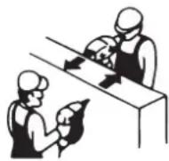
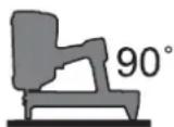
- Always position the Gas Nailer at a 90^ angle to the surface.
Protection of persons:
- Do not hold the handgrip with excessive force.
- Take a work break when feeling numb, extremely warm or cold or a tingling sensation in your fingers/arms. Consult a doctor if this phenomenon repeats.
Property damage:
- Do not use the Gas Nailer in the rain or a very humid environment.
- Do not expose the Gas Nailer to high temperatures, for example the direct sunlight.
- Only use the Gas Nailer in well-ventilated areas or outdoors with temperatures ranging from -10^ to 40^ .
- Do not use the Gas Nailer with an empty magazine.
- Only store the Gas Nailer in dry and frost-protected rooms.
Immediately stop working:
– in case of unusual noises, such as uneven fan noise,
– in case of a strong smell/odour generation (unburned gases),
– in case extreme heat is suddenly being generated,
- if screws or other parts have become loose or fallen off the device.
1.6 Gas Cartridge
Danger of explosion:
- Only store the gas cartridge in well-ventilated rooms. The storage temperatures should not exceed 50 °C.
– Regulations regarding fire and explosion protection during storage, transportation, handling, etc. - Do not store the gas cartridge inside vehicles (cargo holds).
- Do not expose the gas cartridge to high temperatures, for example the direct sunlight.
- Never re-fi II an empty gas cartridge.
- Never open or damage an empty or full gas cartridge, throw it into a fire or smoke in the vicinity.
Dangers to persons:
– Escaping gas can cause injury to the skin.
- Empty gas cartridges can still contain gases, which could cause drowsiness, dizziness and nausea if inhaled.
1.7 Charger and Battery
Danger of explosion:
– Never throw batteries into a fire.
Risk of fi re:
- Only charge the batteries in well-ventilated and dust-free rooms at temperatures ranging from 0^ to 40^ .
- Metal objects may bridge the battery contacts and cause a short circuit. Only storage the battery with the protective cap attached.
- Disconnect the power cord from the power supply after charging.
- Do not "cover up" the charger and battery while charging or expose these components to high temperatures, such as direct sunlight.

- Never charge the battery in the vicinity of fi res or highly fl ammable materials/liquids (thinner, paints/varnishes, gasoline).
- Never connected the power cord to a transformer, power generator, etc.
Risk of electric shock:
- Never charge the batteries in the rain or within the range of splash water. Protect the battery and charger from moisture.
- Keep the power cord free of oil and grease.
Prior to connecting to the power supply:
- Check the mains voltage, see chapter 6 „Technical Data“.
- Never touch the power plug with wet or moist hands.
- Do not route the power cord along sharp edges or hot surfaces.
- Check the power cord and mains socket for damage.
After charging:
- Disconnect the power cord from the power supply. Do not pull on the power cord, pull on the plug instead.
1.8 Disposal
NOTICE Electrical appliances, batteries, chargers and so forth may not be disposed as domestic/household waste. Your dealer is obligated to perform their disposal. Observe local disposal regulations.

2 Unit/Device Overview
2.1 Scope of Delivery
Check the scope of delivery after receipt of the Gas Nailer. Report damaged parts to your specialist dealer.
Scope of delivery: Tool case with Gas Nailer, charger and two batteries.
2.2 Individual Parts and Designations
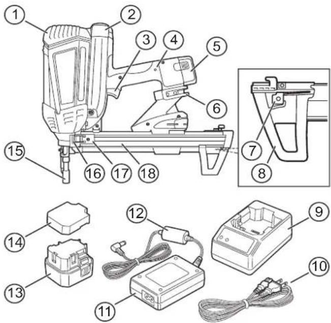
1 Cover (Motor)
2 Cover (Gas Cartridge)
3 Trigger
4 LED Device Indicator
5 Battery
6 Hanging Hook
7 Nail Lock
8 Magazine Foot
9 Charger
10 Power Cord
11 Adapter
12 Charging Cable (Battery)
13 Battery
14 Protective Cap (Battery)
15 Barrel (with Contact Trigger)
16 Magazine Slot
17 Magazine Slider
18 Magazine
2.3 Sleep Mode
The Gas Nailer is equipped with a „Sleep Mode“ function to protect the battery. If the Gas Nailer has not been used for a duration longer than 24 hours, it can only be turned back on after the battery has been removed and re-inserted.
2.4 LED Device Indicator
The LED on the handgrip indicates two different states:
Red LED State/Status
| On Battery has to be charged. | |
| Flashing | Gas Nailer has to be serviced by a specialist workshop. |
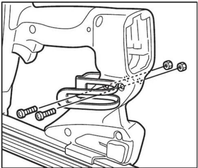
2.5 Hanging Hook
The hanging hook is, for example, used to fasten the device to a belt (when climbing a ladder or scaffolding, etc.) and can be fitted to both sides of the Gas Nailer.
To fasten the hanging hook on the opposite side:
→loosen the screws with a hexagon socket.
→Use these screws to attach the hanging hook on the opposite side.
natural_image
Technical line drawing of a mechanical assembly with bolts and brackets (no text or symbols)2.6 Accessories
Accessories Art.No.
Tool Case DW56514
Charger DDF5610520
Charging Cable DDF5610510
Battery DDF5610500
Magazine, long* DDF5150500
Magazine, short* DDF5150550
Gas Cartridges DDF5140500
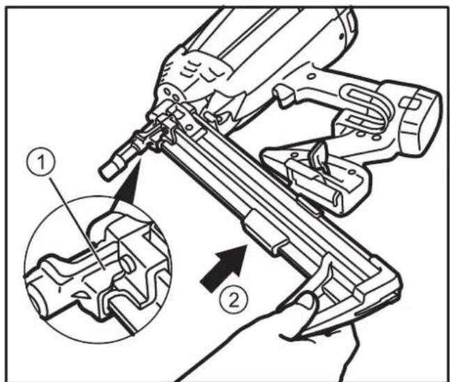
Replacing the magazine:
→Pull the lever used to unlock the magazine and remove the magazine itself.

natural_image
Line drawing of a hand using a tool to adjust or install a mechanical component, with no visible text or symbols.Insert the (new) magazine back into the slot (1) and push it into the magazine receptacle (2).
3 Before using the Device

WARNING
Severe injuries due to improper use
Please read the information in this section carefully before attempting to use the device.
3.1 Charging the battery

WARNING
Risk of electric shock
→Check the power cord for damage before connecting it.
→Keep the battery, charger and power cord away from any moisture.
→Observe the safety instructions, see chapter 1.7 "Charger and Battery".
Maintenance tips:
- A second battery should be acquired to allow for an alternating usage pattern, which serves to extend the service life of the batteries.
- Charge the battery after purchase (prior to first usage) for 24 hours.
- Charge the battery for 24 hours if these are not used for longer than one month.
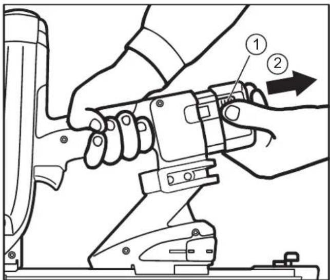
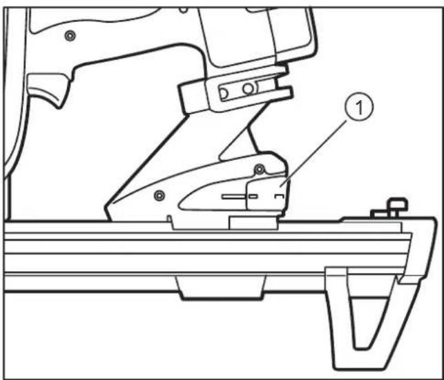
Removing the Battery from the Gas Nailer:
→Press the safety buttons on both sides of the battery (1) and remove the battery from the slot (2).
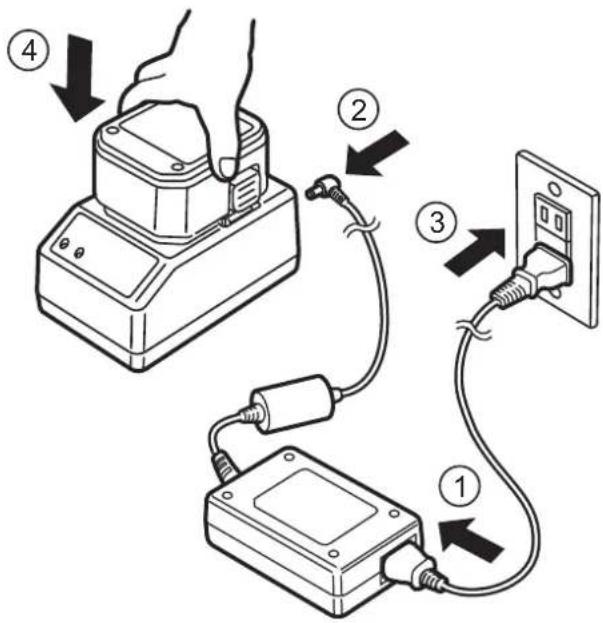
Connecting the Charger:
Connect the power cord to the adapter (1).
Connect the battery charging cable to the charging unit (2).
Connect the power cord to the power supply (3).
→Put the battery into the charger (4).
Charging the Battery:
The charger indicates the current charging status:
| green LED | red LED | Status |
| On Off Charger ready/operational | ||
| Off On Battery is charging | ||
| On Off Battery fully charged | ||
| Flashing Flashing | Battery is overheated: Remove the battery from the charger and let it cool down. | |
| On On | Battery is defective: Remove the battery from the charger and never use it again. | |
| Flashing On | Battery is defective and overheating: Remove the battery from the charger and never use it again. | |
After the battery is fully charged:
→Insert the battery into the Gas Nailer or protect it from short circuits using the protective cap.
→Disconnect the power cord from the power supply (pull the power plug).
3.2 Inserting the Gas Cartridge

WARNING
Serious injuries due to accidental triggering
→Remove the battery.
→Do not press the barrel of the Gas Nailer against any surfaces.
- Keep your finger away from the trigger.
→Observe the safety instructions, see chapter 1.6 "Gas Cartridge".
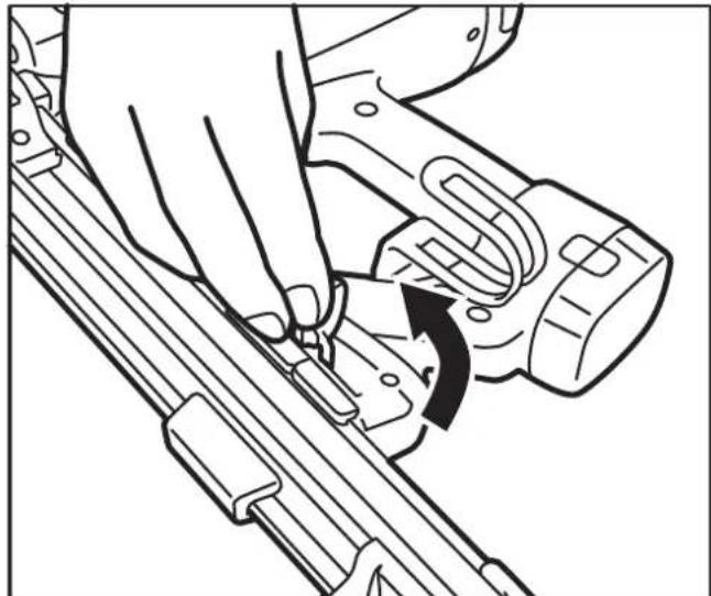
→Press the safety button on the cover/lid (1) and then open it (2).
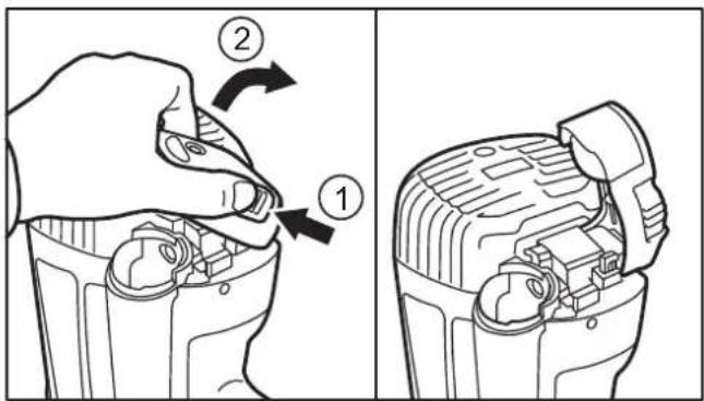
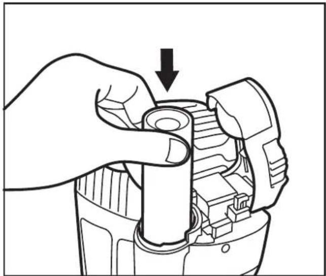
Remove the depleted gas cartridge (if present) and insert the new one.

natural_image
Illustration of a hand adjusting a cylindrical mechanical component with an arrow indicating the process (no text or symbols present)→Close the lid again (locks into place).
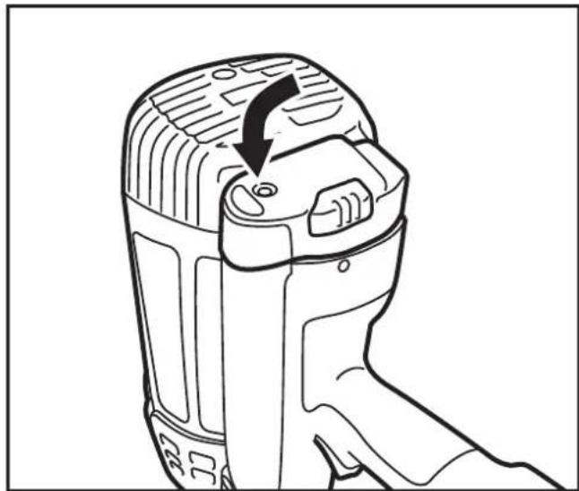
natural_image
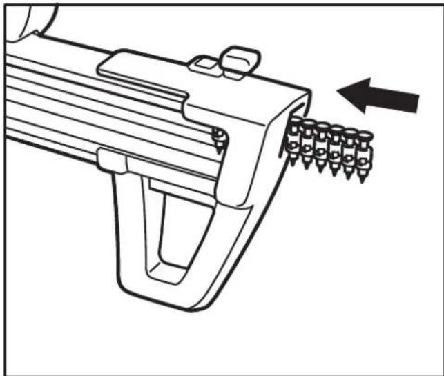
Line drawing of a handheld device with a black arrow indicating a process or operation (no text or symbols present)3.3 Inserting the Nail Strip

WARNING
Serious injuries due to accidental triggering
Remove the battery.
Do not press the barrel of the Gas Nailer against any surfaces.
- Keep your finger away from the trigger.
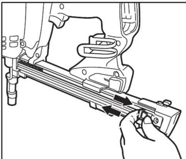
Insert the nail strip into the magazine.
natural_image
Line drawing of a firearm with ammunition being inserted, showing stock position (no text or symbols)→Pull the magazine slider behind the nail strip and release.
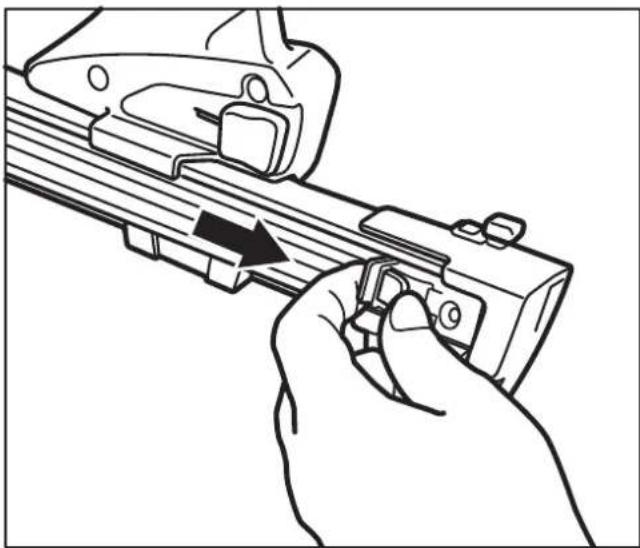
natural_image
Line drawing of a hand holding a firearm with an arrow indicating the grip (no text or symbols present)4 Operation
Observe the safety instructions, see chapter 1.5 „Device and Operational Safety“.
Batteries may discharge by themselves over longer periods of time. Fully charge a battery before usage, see chapter 3.1 „Charging the Battery“.
4.1 Using the Gas Nailer

WARNING
Serious injuries due to accidental triggering
→Always keep the fingers away from the trigger if the Gas Nailer is not facing the target material.
→Always put down/hang the Gas Nailer in such a way that the barrel is pointing downwards.
→Start with a low fi ring depth.
For every workstation change:
→Remove the battery and gas cartridge.
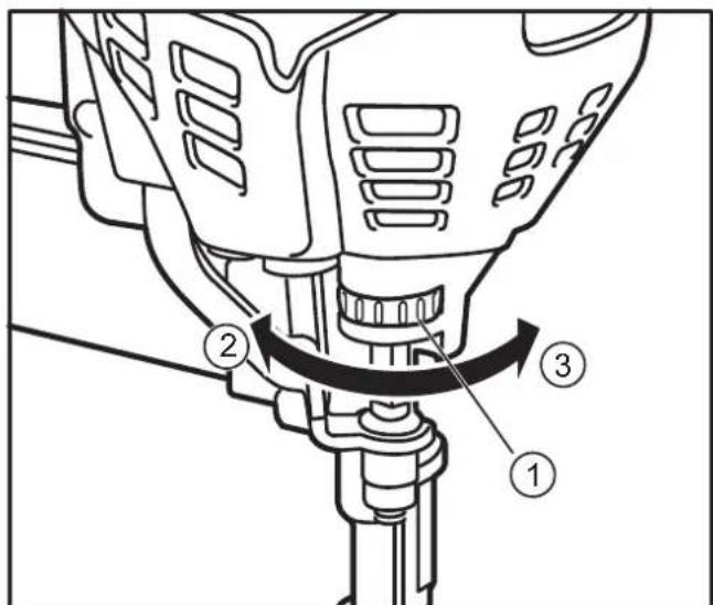
Setting the fi ring depth:
Setting the fi ring depth on the setting wheel (1): Increase: turn in direction (2) Reduce: turn in direction (3).
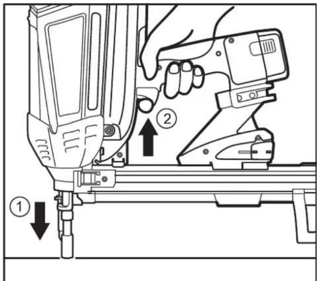
Firing the nails:
Press the barrel against the material to be fastened (1) and press the trigger (2).
If the Gas Nailer does not fire:
- Repeat the process up to three times, replace an empty gas cartridge (if applicable), see chapter 3.2 „Inserting the Gas Cartridge“.
If the Gas Nailer still does not fire, it is possible that the „Sleep Mode“ has activated, see chapter 2.3 „Sleep Mode“.
Remove the battery and insert it again, see the „Removing the battery from the Gas Nailer“ section in chapter 3.1 „Charging the Battery“.
4.2 Removing the Nail Strip

WARNING
Serious injuries due to accidental triggering
→Remove the battery.
→Do not press the barrel of the Gas Nailer against any surfaces.
- Keep your finger away from the trigger.
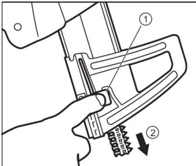
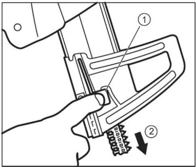
→Unlock the nail strip with the magazine slider.
natural_image
Line drawing of a hand using a tool to adjust or install a mechanical component (no text or symbols visible)Hold the magazine downward while pressing the nail lock (1). The nail strip will slide out of the magazine (2).
4.3 Removing stuck Nails

WARNING
Serious injuries due to accidental triggering
Remove the battery.
→Do not press the barrel of the Gas Nailer against any surfaces.
- Keep your finger away from the trigger.
Remove the nail strip from the magazine, see chapter 4.2 „Removing the Nail Strip“.
→Pull the lever used to unlock the magazine and remove the magazine itself.
natural_image
Line drawing of a hand using a tool to adjust or install a mechanical component, with no visible text or symbols.- If the stuck/jammed nail does not loosen by itself: Remove the nail from the slot (1) with a sharp object.
→Insert the magazine back into the slot (1) and push it into the magazine receptacle (2).

→Move the lever (1) used to lock the magazine back to the starting position (locks into place).
5 Cleaning and Maintenance

WARNING
Serious injuries due to accidental triggering
Remove the battery.
→Remove the gas cartridge.
Remove the nail strip from the magazine, see chapter 4.2 "Removing the Nail Strip".
Do not press the barrel of the Gas Nailer against any surfaces.
- Keep your finger away from the trigger.

CAUTION
Hot surfaces
Let the Gas Nailer cool down prior to cleaning.
NOTICE Malfunctions: Do not oil device components or lubricate them with grease.
5.1 Cleaning the Air Filter
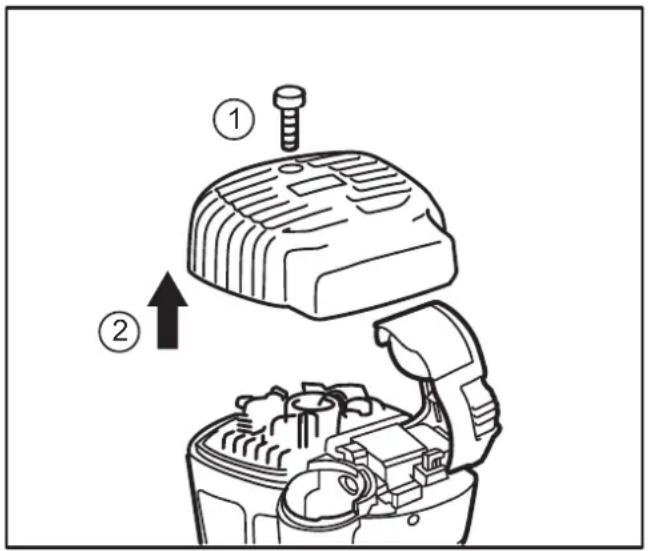
Loosen the screw on the cover/lid (1).
Remove the cover/lid (2).
Clean the air filter in the cover using compressed air.
5.2 Cleaning the Surfaces
NOTICE Damage to surfaces: Do not use any thinners, solvents, gasoline, etc. for cleaning purposes.
– Only clean the Gas Nailer using dry cloths.
- Only clean the tool box with dry cloths and compressed air.
5.3 Maintaining the Gas Nailer
The Gas Nailer may only be maintained and repaired by an authorized specialist workshop. If a maintenance or service measure is required, the LED on the handgrip will start to flash, see chapter 2.4 „LED Device Indicator“.
6 Technical Data
6.1 Gas Nailer
| DDF5110500 DDF5120550 | |
| Height 365 mm 365 mm | |
| Width 124 mm 124 mm | |
| Depth 435 mm 334 mm | |
| Weight including battery and gas cartridge | 3.7 kg 3.6 kg |
| Magazine capacity | 42 nails 22 nails |
| Impact energy 105 J | |
| Battery | 6 VDC, 1.5 Ah |
| Type | Nickel-hydrogen battery |
| Art.No. | DDF5610500 |
| Charger | 100 - 240 VAC, 50/60 Hz |
| Art. No. | DDF5610520 |
| Output | 8 VDC, 1.5 Ah |
| Charging time | 2.5 hours (with battery fully empty) |
| Sound power level* | L_WA = 1 s, d 107.0 dB |
| Emission sound pressure level* | L_pA = 1 s, d 99.3 dB LpC_peak = 131.5 dB K = 3 dB |
| Vibrations* | 18.5 m/s^2, K = 1.6 m/s^2 |
*Values can vary: The work environment, workpiece support, workpiece, contact pressing force and so forth affect the noise development at the place of operation and the effects of vibrations on the object.
6.2 Permissible Nails and Gas Cartridges
| Nails | |
| Length | 15 to 40 mm |
| Diameter | 2.6 mm, 3.0 mm, 3.7 mm |
| Nail head | 6.4 mm |
| Type of nail head | Flat head, round head |
| DEWALT Gas Cartridges | |
| Art.No. | DDF5140500 |
7 Troubleshooting
Barrel is pressed against surface, but engine is not running:
| Cause(s) | Measure(s) |
| Barrel not pressed firmly enough against the surface | Press the barrel harder against the surface |
| The Gas Nailer has not been operated for longer than 24 hours | See chapter 2.3, "Sleep Mode" |
| Electronics faults | Remove the battery and insert it again after 30 seconds |
| Battery is empty | Charge the battery if the LED on the handgrip is flashing, see chapter 2.4 "LED Device Indicator" |
| Battery overheated | Let the battery cool down |
| Gas Nailer overheated | Let the Gas Nailer cool down |
| Gas Nailer has to be serviced | Let the Gas Nailer be serviced if the LED on the handgrip is flashing, see chapter 2.4 "LED Device Indicator" |
| Bent barrel Have the Gas Nailer | |
| Gas Nailer defective | be repaired by an authorized dealer |
Barrel is pressed against the surface, but motor stops after 5 seconds:
| Cause(s) | Measure(s) |
| Normal function | No measures |
Barrel is firmly pressed against the surface, the motor is running, but the nails are not fired when the trigger is pressed:
| Cause(s) | Measure(s) |
| Gas cartridge empty or not filled to a sufficient degree | See chapter 3.2, "Insert Gas Cartridge" |
| Stuck/jammed nails | See chapter 4.3,Removing stuck Nails" |
Cause(s) Measure(s)
| No nails in the magazine | See chapter 3.3, "Inserting the Nail Strip" |
| Magazine slider not retracted | |
| Forbidden or unauthorized nails in the magazine | See chapter 6.2, "Permissible Nails and Gas Cartridges" |
| Magazine "bent" or not inserted properly | See the "Replacing the Magazine" section in chapter 2.6, "Accessories" |
| Magazine slider spring defective | |
| Foreign object in the barrel or magazine | See chapter 4.3, Removing stuck Nails" |
| Gas Nailer defective | Have the Gas Nailer be repaired by an authorized dealer. |
Barrel is firmly pressed against the surface, the motor is running, but the nails do not penetrate deeply enough into the material after pressing the trigger:
Cause(s) Measure(s)
| Gas cartridge empty or not filled to a sufficient degree | See chapter 3.2, "Insert Gas Cartridge" |
| Firing depth set too low | See "Setting the Firing Depth" section in chapter 4.1, "Using the Gas Nailer" |
| Nails too long, diameter too large | Use a nail that matches the target material |
| Target material too hard | |
| Nail strikes hard foreign objects in the target material, such as other nails | Aim the Gas Nailer elsewhere |
| Test the Gas Nailer on a different target material | |
| Gas Nailer not pressed firmly enough against the target material | Do not hold the Gas Nailer "too loosely" in your hands |
| Gas Nailer defective | Have the Gas Nailer be repaired by an authorized dealer. |
Barrel is firmly pressed against the surface, the motor is running, but the nails penetrate too deep into the material after pressing the trigger:
Cause(s) Measure(s)
| Firing depth set too high | See "Setting the Firing Depth" section in chapter 4.1, "Using the Gas Nailer" |
| Nails too short, diameter too small | Use a nail that matches the target material |
| Target material too soft | |
| Nail strikes cavities or soft foreign objects in the target material | Aim the Gas Nailer elsewhere |
| Test the Gas Nailer on a different target material |
Loud or irregular fan noise:
Cause(s) Measure(s)
| Air fi Iter dirty | See chapter 5.1, "Cleaning the Air Filter" |
| Fan defective | Have the Gas Nailer be repaired by an authorized dealer. |
Gas odours (unburned combustion gases):
Cause(s) Measure(s)
| When the barrel is pressed against a surface, the motor directs an explosive gas into the combustion chamber. If the trigger is not actuated, another press causes the unburned gas to escape | See chapter 1.5, "Device and Operational Safety" |
8 Manufacturer Warranty
DEWALT trusts in the quality of its products and therefore offers professional users of the product an outstanding warranty. This warranty is merely an addition and does not affect your rights derived from your contract as a professional user or your legal rights as a private, non-professional user of the device. This warranty is valid within the territories of the Member States of the European Union and the European Free Trade Association.
Full warranty for one year
If your DEWALT product suffers from a fault due to material or production defects within 12 months after purchase, DEWALT guarantees the free replacement of all faulty parts or the free replacement of the device (at our discretion) under the following conditions:
– The product was not handled improperly;
– The product was exposed to normal wear and tear;
– No repair attempts were made by unauthorized persons;
– A proof of purchase is submitted;
- The product is returned complete in its original packaging.
In order to submit a warranty claim, please contact a DEWALT service partner in your area (whose address can be found in the DEWALT catalogue) or contact the DEWALT offi ce specifi ed in this instruction manual. A list of authorized DEWALT customer service workshops and more information regarding our customer service can be found on the Internet an: www.2helpU.com.
9 Declaration of Conformity

In accordance with Machinery Directive
2006/42/EC
Product: Gas Actuated Nailer (Gas Nailer)
Types: D EWALT DDF5110500
DeWALT DDF5120550
The designated product corresponds to the provisions of Machinery Directive 2006/42/EC as well as the harmonized EN 792-13:2000 + A1:2008 standard.
The signatory is responsible for compiling the technical documents and submits this declaration on behalf of D EWALT.
For more information, please contact D EWALT at the following address. For additional addresses, please refer to the backside of this instruction manual.

Colin Earl
Idstein, April 11 2014
Vice President HTF Construction and DIY Europe
D-65510, Idstein, Germany
CLAVADORA DE GAS Trak-lt® C5 DDF5110500, DDF5120550
natural_image
Technical line drawing of a mechanical assembly with bolts and brackets (no text or symbols)2.6 Accesorios
Accesorios N.º art.
natural_image
Line drawing of a hand using a tool to adjust or install a mechanical component, with no visible text or symbols.natural_image
Illustration of a hand holding a cylindrical mechanical component with an arrow indicating assembly or disassembly (no text or symbols present)natural_image
Line drawing of a handheld device with a black arrow indicating rotation or movement (no text or symbols)natural_image
Line drawing of a firearm with an arrow pointing to the bullet array (no text or symbols present)natural_image
Line drawing of a hand holding a firearm with an arrow indicating motion (no text or symbols)4 Operación
Disparo de clavos:
natural_image
Line drawing of a hand using a tool to adjust or install a mechanical component (no text or symbols visible)natural_image
Line drawing of a hand using a tool to adjust or install a mechanical component, with no visible text or symbols.Idstein, April 11 2014
Vicepresidente HTF Construction and DIY Europe
natural_image
Technical line drawing of a mechanical assembly with bolts and brackets (no text or symbols)2.6 Accessoires
natural_image
Line drawing of a hand adjusting a mechanical component with a curved arrow indicating rotation (no text or symbols)natural_image
Line drawing of a hand adjusting a mechanical component with an arrow indicating the process (no text or symbols present)natural_image
Line drawing of a handheld device with a black arrow indicating a process or operation (no text or symbols present)natural_image
Line drawing of a firearm with ammunition being inserted, showing stock position and movement direction (no text or symbols)natural_image
Line drawing of a hand holding a firearm with an arrow indicating the grip (no text or symbols present)4 Fonctionnement
Tir des clous :
natural_image
Line drawing of a hand using a tool to adjust or install a mechanical component (no text or symbols visible)4.3 Retrait des clous coincés

AVERTISSEMENT
natural_image
Technical line drawing of a mechanical assembly with a hand adjusting a component (no text or symbols present)Cause(s) Solution (s)
Cause(s) Solution (s)
Cause(s) Solution (s)
Cause(s) Solution (s)
Cause(s) Solution (s)
Vice President HTF, Construction et bricolage Europe
natural_image
Technical line drawing of a mechanical assembly with bolts and brackets (no text or symbols)2.6 Accessori
Accessori Art. N.
natural_image
Line drawing of a hand using a tool to adjust or install a mechanical component, with no visible text or symbols.natural_image
Illustration of a hand turning a cylindrical component into a mechanical housing (no text or symbols)natural_image
Line drawing of a handheld device with a black arrow indicating rotation or movement (no text or symbols)natural_image
Line drawing of a firearm with an arrow pointing to the bullet point (no text or symbols present)natural_image
Line drawing of a hand using a tool to adjust or install a firearm component (no text or symbols present)4 Utilizzo
natural_image
Line drawing of a hand using a tool to adjust or install a mechanical component (no text or symbols visible)natural_image
Line drawing of a hand using a tool to adjust or install a mechanical component, with no visible text or symbols.Construction and DIY Europe
1 Behuizing (Motor) 10 Netsnoer
2 Behuizing 11 Adapter
(Gaspatroon)
12 Oplaadkabel (Accu)
3 Trekker 13 Accu
4 LED indicator 14 Beschermkap
5 Accu (Accu)
6 Ophanghaak 15 Loop (met contact)
natural_image
Technical line drawing of a mechanical assembly with bolts and brackets (no text or symbols)2.6 Accessoires
| Accessoires Art.Nr. |
| Gereedschapskist DW56514 |
| Acculader DDF5610520 |
| Oplaadkabel DDF5610510 |
| Accu DDF5610500 |
| Magazijn, lang* DDF5150500 |
| Magazijn, kort* DDF5150550 |
| Gaspatronen DDF5140500 |
natural_image
Line drawing of a hand adjusting a mechanical component with a curved arrow indicating rotation (no text or symbols)De accu opladen:
natural_image
Illustration of a hand adjusting a mechanical component with an arrow indicating the process (no text or symbols present)natural_image
Line drawing of a handheld device with a black arrow indicating rotation or movement (no text or symbols)natural_image
Line drawing of a firearm with an arrow indicating movement or force direction (no text or symbols present)natural_image
Line drawing of a hand holding a firearm with an arrow indicating the grip (no text or symbols present)4 Bediening
De nagels afvuren:
natural_image
Line drawing of a hand operating a mechanical device with arrows indicating motion (no text or symbols)natural_image
Line drawing of a hand using a tool to adjust or install a mechanical component, with no visible text or symbols.5.2 De behuizing reinigen
Idstein, April 11 2014
Vice President HTF Construction and DIY Europe
1 Motordeksel
10 Strømkabel
2 Gasspatrondeksel
11 Strømadapter
3 Avtrekker
12 Ladekabel for batterilader
4 LED-lampe
5 Batteri
13 Batteri
6 Krok
14 Batterilokk
7 Spikerlås
15 Løp (med sikring)
8 Magasinfot
16 Magasinfeste
9 Lader
17 Matesko
18 Magasin
2.3 Hvilemodus
natural_image
Technical line drawing of a mechanical assembly with bolts and brackets (no text or symbols)2.6 Tilbehør
Tilbehør Delenr.
natural_image
Line drawing of a hand using a tool to adjust or install a mechanical component, with no visible text or symbols.Lade batteriet:
Laderen viser gjeldende ladestatus:
3.2 Sette inn gasspatron

ADVARSEL
→Fjern den tomme gasspatronen (dersom relevant) og sett inn en ny patron.
natural_image
Line drawing of a hand adjusting a cylindrical component with an arrow indicating the process (no text or symbols present)natural_image
Line drawing of a handheld device with a black arrow indicating rotation or movement (no text or symbols)3.3 Sette inn spikerremse

ADVARSEL
natural_image
Line drawing of a firearm with ammunition being inserted, showing stock position and movement direction (no text or symbols)natural_image
Line drawing of a hand holding a firearm with an arrow indicating the grip (no text or symbols present)4 Bruk
Fyre av spiker:
4.2 Fjerne spikerremsen

ADVARSEL
natural_image
Technical line drawing of a mechanical assembly with a hand operating a tool (no text or symbols present)Hold magasinet nedover samtidig som du trykker på spikerlåsen (1). Spikerremsen vil gli ut av magasinet (2).
4.3 Fjerne fastläste spiker

ADVARSEL
natural_image
Line drawing of a hand using a tool to adjust or install a mechanical component, with no visible text or symbols.Gasslukt (ubrent gass):
e m l e g g e s Colin Earl
Idstein, 11. April 2014
Direktør HTF
1 Tampa (motor)
2 Tampa (cartucho de gás)
3 Gatilho
4 Indicador LED do dispositivo
5 Bateria
6 Gancho para pendurar
natural_image
Technical line drawing of a mechanical assembly with bolts and brackets (no text or symbols)2.6 Acessórios
Acessórios N.º art.
Estojo de ferramentas DW56514
Carregador DDF5610520
Cabo de carregamento DDF5610510
Bateria DDF5610500
Carregador, comprido* DDF5150500
Carregador, pequeno* DDF5150550
Cartuchos de gás DDF5140500
Substituir o carregador:
natural_image
Line drawing of a hand using a tool to adjust or install a mechanical component, with no visible text or symbols.3 Antes de utilizar o dispositivo

AVISO
Ligar o carregador:
Carregar a bateria:
O carregador indica o estado de carregamento actual:
natural_image
Illustration of a hand holding a cylindrical device with an arrow pointing to it, showing internal components (no text or symbols)natural_image
Line drawing of a handheld device with a black arrow indicating rotation or movement (no text or symbols)3.3 Inserir o cartucho de pregos

AVISO
natural_image
Line drawing of a firearm with an arrow pointing to the bullet point (no text or symbols present)natural_image
Line drawing of a hand holding a firearm with an arrow indicating motion (no text or symbols)4 Funcionamento
Disparar os pregos:
4.2 Retirar o cartucho de pregos

AVISO
natural_image
Line drawing of a hand operating a mechanical assembly with arrows indicating motion (no text or symbols)4.3 Retirar pregos presos

AVISO
natural_image
Line drawing of a hand using a tool to adjust or install a mechanical component, with no visible text or symbols.5.2 Limpar as superfícies
Vice-Presidente da HTF Construction and DIY Europe
natural_image
Illustration showing two workers handling a baby on a conveyor belt, with a 90-degree angle indicator below (no text or symbols on the figures)1 Kansi (moottori)
natural_image
Technical line drawing of a mechanical assembly with bolts and brackets (no text or symbols)2.6 Lisävarusteet
natural_image
Line drawing of a hand using a tool to adjust or install a mechanical component, with no visible text or symbols.Akun lataaminen:
natural_image
Illustration of a hand adjusting a cylindrical mechanical component with an arrow indicating the process (no text or symbols present)natural_image
Line drawing of a handheld device with a black arrow indicating rotation or movement (no text or symbols)natural_image
Line drawing of a firearm with ammunition being inserted, showing stock position (no text or symbols)natural_image
Line drawing of a hand using a firearm to adjust the dose (no text or symbols present)4 Käyttö
Naulojen laukaisminen:
natural_image
Line drawing of a hand operating a mechanical device with arrows indicating movement or force (no text or symbols present)natural_image
Technical line drawing of a mechanical assembly with a hand adjusting a component (no text or symbols present)Colin Earl
D-65510, Idstein, Germany
Trak-It® C5 GASDRIVEN SPIKPISTOL DDF5110500, DDF5120550
natural_image
Technical line drawing of a mechanical assembly with bolts and brackets (no text or symbols)2.6 Tillbehör
Tillbehör Art nr
natural_image
Line drawing of a hand using a tool to adjust or install a mechanical component, with no visible text or symbols.Ansluta laddaren:
Ladda batteriet:
natural_image
Illustration of a hand adjusting a mechanical component with a downward arrow indicating action (no text or symbols present)natural_image
Line drawing of a handheld device with a black arrow indicating rotation or movement (no text or symbols)natural_image
Line drawing of a firearm with an arrow pointing to the bullet array (no text or symbols present)natural_image
Line drawing of a hand holding a firearm with a black arrow indicating the handle (no text or symbols present)4 Användning
Skjuta spik:
4.2 Ta ut bandade spikar

WARNING
natural_image
Line drawing of a hand operating a mechanical device with arrows indicating motion (no text or symbols)natural_image
Line drawing of a hand using a tool to adjust or install a mechanical component, with no visible text or symbols.5.2 Rengöra ytor
Vice vd HTF Construction and DIY Europe
natural_image
Technical line drawing of a mechanical assembly with bolts and brackets (no text or symbols)2.6 Αξεσουάρ
natural_image
Line drawing of a hand using a tool to adjust or install a mechanical component, with no visible text or symbols.natural_image
Illustration of a hand using a mechanical component to adjust or install a cylindrical part, with no visible text or symbols.natural_image
Line drawing of a handheld device with a black arrow indicating rotation or movement (no text or symbols)natural_image
Line drawing of a firearm with ammunition being inserted, showing stock position and movement direction (no text or symbols)natural_image
Line drawing of a hand using a tool to adjust or install a firearm (no text or symbols present)4 Λειτουργία
natural_image
Line drawing of a hand using a tool to adjust or install a mechanical component (no text or symbols visible)natural_image
Line drawing of a hand using a tool to adjust or install a mechanical component, with no visible text or symbols.D-65510, Idstein, Germany
| Belgique et Luxembourg België en Luxemburg | DEWALT - Belgium BVBA Egide Walschaertsstraat 16 2800 Mechelen | Tel: NL 32 15 47 37 63 Tel: FR 32 15 47 37 64 Fax: 32 15 47 37 99 | www.dewalt.be enduser.BE@sBDinc.com |
| Danmark D | EWALT Roskildevej 22 2620 Albertslund | Tel: 70 20 15 10 Fax: 70 22 49 10 | www.dewalt.dk kundeservice.dk@sbdinc.com |
| Deutschland D | EWALT Richard Klinger Str. 11 65510 Idstein | Tel: 06126-21-1 Fax: 06126-21-2770 | www.dewalt.de infodwge@sbdinc.com |
| Ελλάς D | EWALT (Ελλάς) A.E. ΕΔΡΑ-ΓΡΑΦΕΙΑ : Στράβωνος 7 & Λ. Βουλιαγμένης, Γλυφάδα 166 74, Αθήνα SERVICE : Ημερος Τόπος 2 (Χάνι Αδάμ) – 193 00 Ασπρόπυργος | Tηλ: 00302108981616 Φαξ: 00302108983570 | www.dewalt.gr Greece.Service@sbdinc.com |
| España D | EWALT Ibérica, S.C.A. Parc de Negocios “Mas Blau” Edificio Muntadas, c/Bergadá, 1, Of. A6 08820 El Prat de Llobregat (Barcelona) | Tel: 934 797 400 Fax: 934 797 419 | www.dewalt.es respuesta.postventa@sbdinc.com |
| France D | EWALT 5, allée des Hêtres BP 30084, 69579 Limonest Cedex | Tel: 04 72 20 39 20 Fax: 04 72 20 39 00 | www.dewalt.fr scufr@sbdinc.com |
| Schweiz Suisse Svizzera | DEWALT In der Luberzen 42 8902 Urdorf | Tel: 044 - 755 60 70 Fax: 044 - 730 70 67 | www.dewalt.ch service@rofoag.ch |
| Ireland D | EWALT Calpe House Rock Hill Black Rock, Co. Dublin | Tel: 00353-2781800 Fax: 00353-2781811 | www.dewalt.ie |
| Italia D | EWALT via Energypark 20871 Vimercate (MB), IT | Tel: 800-014353 39 039 9590200 Fax: 39 039 9590313 | www.dewalt.it |
| Nederlands | DEWALT Netherlands BV Holtum Noordweg 35 6121 RE BORN, Postbus 83, 6120 AB BORN | Tel: 31 164 283 063 Fax: 31 164 283 200 | www.dewalt.nl |
| Norge | DEWALT Postboks 4613, Nydalen 0405 Oslo | Tel: 45 25 13 00 Fax: 45 25 08 00 | www.dewalt.no kundeservice.no@sbdinc.com |
| Österreich | DEWALT Werkzeug Vertriebsges m.b.H Oberlaaerstrasse 248, A-1230 Wien | Tel: 01 - 66116 - 0 Fax: 01 - 66116 - 614 | www.dewalt.at service.austria@sbdinc.com |
| Portugal | DEWALT Limited, SARL Centro de Escritórios de Sintra Avenida Almirante Gago Coutinho, 132/134, Edificio 14 2710-418 Sintra | Tel: 214 66 75 00 Fax: 214 66 75 80 | www.dewalt.pt resposta.posvenda@sbdinc.com |
| Suomi | DEWALT PL 47 00521 Helsinki | Puh: 010 400 4333 Faksi:0800 411 340 | www.dewalt.fi asiakaspalvelu.fi@sbdinc.com |
| Sverige | DEWALT Box 94 431 22 Mölndal | Tel: 031 68 61 60 Fax: 031 68 60 08 | www.dewalt.se kundservice.se@sbdinc.com |
| Türkiye | KALE Hírdavat ve Makina A.Ş. Defterdar Mah. Savaklar Cad. No:15 Edimekapı / Eyüp / İSTANBUL 34050 TÜRKİYE | Tel: 0212 533 52 55 Faks: 0212 533 10 05 | www.dewalt.com.tr |
| United Kingdom | DEWALT, 210 Bath Road; Slough, Berks SL1 3YD | Tel: 01753-567055 Fax: 01753-572112 | www.dewalt.co.uk emeaservice@sbdinc.com |
| Australia | DEWALT 82 Taryn Drive, Epping VIC 3076 Australia | Tel: Aust 1800 338 002 Tel: NZ 0800 339 258 | www.dewalt.com.au www.dewalt.co.nz |
| Middle East Africa | DEWALT P.O. Box - 17164, Jebel Ali Free Zone (South), Dubai, UAE | Tel: 971 4 812 7400 Fax: 971 4 2822765 | www.dewalt.ae Service.MEA@sbdinc.com |