WRP 1000 Classic - Water filter Kärcher - Free user manual and instructions
Find the device manual for free WRP 1000 Classic Kärcher in PDF.

| Product type | Water filter for washing installation |
| Brand | Kärcher |
| Model | WRP 1000 Classic |
| Dimensions (L × W × H) | 660 mm × 470 mm × 980 mm |
| Weight | 45 kg |
| Nominal flow rate | 1000 l/h |
| Operating pressure | 0.2 – 0.35 MPa (2 – 3.5 bar) |
| Supply | Connection to site submersible pump (not supplied) |
| Main functions | Filtration of oil-free wastewater, backwashing, service water circulation, frost protection |
| Filter type | Filament filter |
| Intended use | Treatment of vehicle wash wastewater for reuse |
| Maintenance and cleaning | Daily backwashing, weekly cleaning of the collector, monthly draining of the service water tank, annual replacement of the filter cartridge |
| Safety | Shut down submersible pump before any intervention; use by qualified personnel; frost protection |
| Spare parts and repairability | Filter element (p/n 5.033-239.0), fresh water switching kit (p/n 2.641-521.0) |
| General information | Installation reserved for Kärcher specialists; warranty according to local conditions |
Frequently Asked Questions - WRP 1000 Classic Kärcher
User questions about WRP 1000 Classic Kärcher
0 question about this device. Answer the ones you know or ask your own.
Ask a new question about this device
Download the instructions for your Water filter in PDF format for free! Find your manual WRP 1000 Classic - Kärcher and take your electronic device back in hand. On this page are published all the documents necessary for the use of your device. WRP 1000 Classic by Kärcher.
USER MANUAL WRP 1000 Classic Kärcher
natural_image
Technical line drawing of a mechanical assembly with pipes, valves, and a cylindrical component (no text or symbols)Deutsch 3
English 8
Français 13
Italiano 18
Nederlands 23
Español 28
Português 34
Dansk 40
Norsk 45
Svenska 50
Suomi 55
Ελληνικά 60
Türkçe 66
Русский 71
Magyar 77
Čeština 82
Slovenščina 87
Polski 92
Românește 98
Slovenčina 104
Hrvatski 109
Srpski 114
Български 119
Eesti 125
Latviešu 130
Lietuviškai 135
Українська 140
1 Spannhebel
1 Mutter
2 Spannhebel
1 Nutenstein
natural_image
Diagram of a mechanical component with internal structure and directional arrows (no text or symbols)natural_image
Technical line drawing of a mechanical assembly with no visible text or symbolsPlease read and comply with these original instructions prior
to the initial operation of your appliance and store them for later use or subsequent owners.
Contents
About this Operations Manual EN .. 1
Environmental protection .. EN .. 1
Warranty ..... EN .. 1
Safety instructions ..... EN .. 1
Operation ..... EN .. 1
Transport ..... EN .. 2
Storage....EN..2
Function ..... EN .. 2
Technical specifications ... EN .. 2
Maintenance and care .... EN .. 3
Troubleshooting ..... EN .. 5
Accessories ..... EN .. 5
Installing the unit (only for experts). EN . 5
About this Operations Manual
Target group for these instructions
About this Operations Manual
– All users: Users include trained auxiliary personnel, operators and experts.
- Experts: Experts are individuals, who are, according to their professional education, able to install the equipment and to operate the same.
Definitions
Fresh water
Tap water
Waste water
Dirty water discharged from the high-pressure cleaner washing unit
Processed water
Water prepared by the system for reuse in the washing programmes (preliminary washing, brush washing, high pressure cleaning, underbody cleaning) in the vehicle washing system or the high-pressure cleaner.
Environmental protection

The packaging materials are recyclable. Please do not throw packaging in the domestic waste but pass it on for recycling.

Old units contain valuable recyclable materials. Batteries, oil and similar substances may not be released into the environment. Therefore please dispose of old units through suitable collection systems.
Notes about the ingredients (REACH)
You will find current information about the ingredients at:
www.kaercher.com/REACH
Warranty
The warranty terms published by our competent sales company are applicable in each country. We will repair potential failures of your appliance within the warranty period free of charge, provided that such failure is caused by faulty material or defects in fabrication. In the event of a warranty claim please contact your dealer or the nearest authorized Customer Service center. Please submit the proof of purchase.
Safety instructions
Symbols used in the operation instruction
The following symbols are used in this operating manual:
⚠️Danger!
Indicates an immediate danger. By not paying attention to this notice, there is danger of death or serious injury.
⚠ Warning
Indicates a possible dangerous situation.
By not paying attention to the notice, light injuries or property damage may possibly occure.
Notice
Indicates operating idea and important information.
General
To avoid danger to persons, animals and property before the first operation of the system, read:
– this operating instructions manual, especially the safety instructions contained therein
– the enclosed "Safety instructions for waste water treatment plants"
– the respective national statutes of the legislator
All individuals, who are involved, in the installation, the operation, the maintenance and service of this equipment, must be
– have the requisite qualifications,
– know and observe the "Safety instructions for waste water treatment plants",
– know and have read this operations manuals,
– know and follow the corresponding regulations.
The appliance may only be used by persons who have been instructed in handling the appliance or have proven qualification and expertise in operating the appliance or have been explicitly assigned the task of handling the appliance.
This appliance is not intended for use by persons with reduced physical, sensory or mental capabilities.
The appliance must not be operated by children or persons who have not been instructed accordingly.
⚠️Danger
Do not drink the processed water - health hazard. The cleaned waste water is not of a potable quality. It still contains some residues of dirt and detergents.
Proper use
The system cleans oil-free dirt water discharged from vehicle cleaning and provides processed water to the high-pressure cleaner or the vehicle washing systems that have low water consumption (max. 1000 litres per hour). The used water can only be used for cleaning programmes (for e.g. preliminary washing, high pressure cleaning, brush cleaning). Processed water is not suitable for use as rinsing water or for applying drying aid or some other such purpose.
Cleaning is done by:
- Separating heavy parts that easily settle down in the gravel filter.
Pre-requisites for smooth functioning: - Basin system according to the water flow diagram shown in the "Function" chapter.
– Oil-free waste water in circulation in the system.
Operation
Operating elements
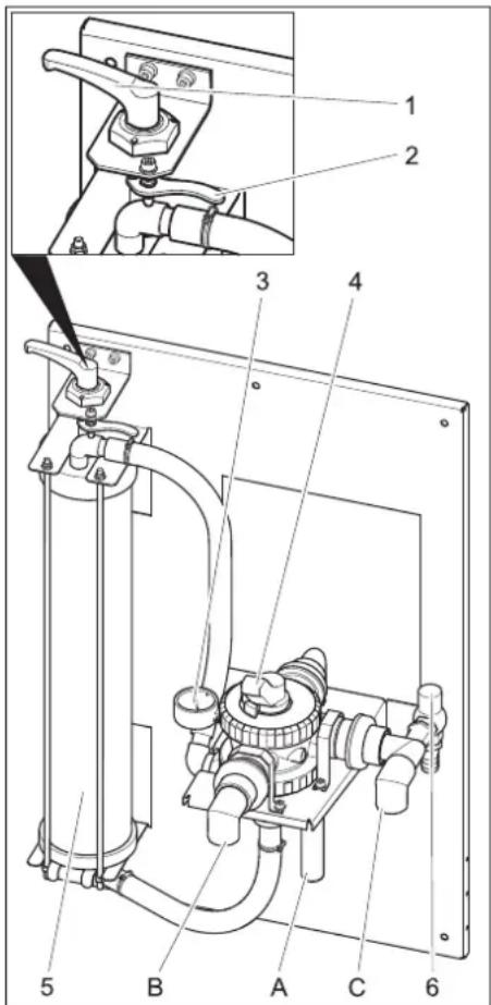
1 Tension lever
2 Unlocking lever
3 Manometer at the filter inlet
4 Multi-channel valve
5 Filament filter
6 Overflow valve
A to collect sludge (rinse back)
B to the high-pressure cleaner / processed water tank (filling)
C from the immersion pump
Adjust the filter pre-tension
Proceed as follows to subsequently change the filter tension:
→ Turn the tension lever to the left until the lever reaches the stop.
→ Pull the unlocking lever towards the front and turn the tightening lever toward the right until the unlocking lever locks in in the next nose.
Filter operations
→ Turn the lever of the multi-channel valve in "FILTRATION" position.
Note
After longer idling times it takes a lot of effort to activate the multi-channel valve.
→ Check filter pre-tension.
→ Start the pump in the building.
Backwash
Note
During normal operations, you must backwash the filter at least once daily. The system does not release any processed water during the back-rinsing process..
During backwash, the dirt collected in the filament filter is removed. To do this, the filament filter is rinsed in the reverse direction. According to the local regulations, the rinsed out dirt is either directed into the sludge collection of the recycling system, an existing disposal chain or the drainage.
→ Start the pump in the building.
→ Turn the lever of the multi-channel valve in "RÜCKSPÜLEN/BACKWASH" position.
→ Loosen the filament filter by turning the tension lever in the anti-clockwise direction.
→ Wait for 30 seconds.
→ Tighten the filament filter and loosen it immediately.
→ Repeat ten times this process of waiting for 10 minutes - tightening - loosening.
→ Reset the filter pre-tension.
→ Turn the lever of the multi-channel valve in "ERSTFILTRAT/RINSE" position.
→ Wait 2 minutes
→ Turn the lever of the multi-channel valve in "FILTRATION" position.
Processed water circulation
If the high-pressure cleaner or the washing system does not use up the water, the processed water is circulated to avoid foul odour.
Note
The immersion pump can be periodically switched on/off during non-operating hours (for e.g. at night, over the week-end) to lower the operating hours. For this you can connect the immersion pump via a timer to the power supply.
Maximum interval increment: 1 hour.
Frost protection
The plant must be operated in frost-free rooms. During frost, put the system out of operation and remove all traces of water:
→ Pull out the hoses.
→ Let the system dry-run.
Shutdown
→ Switch off the building pump.
→ If there is risk of frosting, then any existing water traces must be removed (see section "Anti-freezing").
Transport
Caution
Risk of injury and damage! Observe the weight of the appliance when you transport it.
→ When transporting in vehicles, secure the appliance according to the guidelines from slipping and tipping over.
Storage
Caution
Risk of injury and damage! Note the weight of the appliance in case of storage.
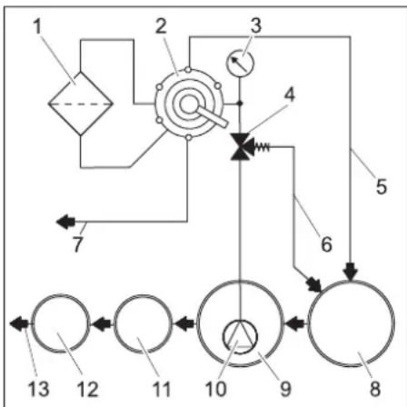
Function
Flow pattern
flowchart
graph TD
    1["Component 1"] --> 2["Component 2"]
    2 --> 3["Component 3"]
    3 --> 4["Component 4"]
    4 --> 5["Component 5"]
    5 --> 6["Component 6"]
    6 --> 7["Component 7"]
    7 --> 8["Component 8"]
    8 --> 9["Component 9"]
    9 --> 10["Component 10"]
    10 --> 11["Component 11"]
    11 --> 12["Component 12"]
    12 --> 13["Component 13"]
1 Filament filter
2 Multi-channel valve
3 Manometer at the filter inlet
4 Overflow valve
5 Backwash pipe
6 Circulation (to sludge collector)
7 To the processed water tank/ high-pressure cleaner
8 Sludge collection of the recycling system *)
9 Pump basin of the recycling system *)
10 Immersion pump *)
11 Separation system (EN 858) *)
12 Control shaft *)
13 to drainage system *)
*) on building side
Functional description
The following section describes the flow-path of the water in different positions of the multi-channel valve.
FILTRATION
In filter operations, the water flows via
- Immersion pump
- Multi-channel valve in "FILTRATION" position
- Filter (flow direction of filtering)
- To the high-pressure cleaner/processed water tank
RÜCKSPÜLEN/BACKWASH
During backwash, the water flows via
- Immersion pump
- Multi-channel valve in position RÜCK-SPÜLEN/BACKWASH"
- Filter (against flow direction of filtering)
- To the sludge collector
ERSTFILTRAT/RINSE
During final rinse the water flows via:
- Immersion pump
– Multi-channel valve in position ERST-FILTRAT/RINSE - Filter (flow direction of filtering)
- To the sludge collector
UMWÄLZUNG/RECIRCULATION
This position is not required for operating the system.
Technical specifications
| WRP1000eco | WRP1000compact | ||
| Pressure (min.) | MPa(bar) | 0,2 (2) | |
| Pressure(max.) | MPa(bar) | 0,35 (3,5) | |
| Filter capacity l/h | 1000 | ||
| Width mm 660 | |||
| Depth mm 470 | |||
| Height mm 980 | 1230 | ||
| Weight | kg | 45 | |
Immersion pump requirements (building-side)
| Pressure (min.) MPa | (bar) | 0,2 (2) |
| Pressure (max.) MPa | (bar) | 0,35(3,5) |
| Minimum flow rate at 0.2 MPa (2 bar) | l/h | 1000 |
- Suitable for dirt water
– Suitable for continuous operations
– With protection against dry-run
Maintenance and care
Maintenance instructions
The bases of a safe operating of the equipment is thr regularly maintenance according to the following maintenance plan. Use only original parts of the manufacturer or part suggested by him, such as
- parts and wearing parts,
- accessories parts,
– operating materials, - cleaning agents.
⚠️Danger
Risk of accident while working on the unit. During all tasks
→ Shut off water supply.
→ Switch off the immersion pump in the building.
Who may perform maintenance?
- operator
Performances containing the notice "operator" may only be performed by instructed individuals, who are able to operate and service high pressure equipment.
- Maintenance
Performances with the notice "maintenance" may only be performed by the Kärcher-Maintenance-Mechanics.
Maintenance contract
In order to guarantee a reliable operation og the equipment, we success, you signed a maintenance agreement. Please refer to you local Kärcher service department.
Maintenance schedule
| Time Activity Assembly affected | Performance By whom | |||
| daily Backwash Filament filter Run bachwash Operator | ||||
| weekly Clean the filter | Drain at washing place | Clean the dirt collection basket in the floor. Operator | ||
| opinion Detector concentration in processed water | Reduce the detergent dosing at the detergent dispenser if there is foam formation. | Operator | ||
| monthly | opinion Sludge collection, pump basin | After sludge has been collected, there should be no sludge in any of the basins. The sludge in the sludge collector should be maximum 1 m in height. Check sludge level; pump out and dispose off the sludge according to the local regulations, if required. | Operator | |
| empty, clean | Processed water tank (if available) | Empty, clean, rinse and refill. | Operator | |
| Half-yearly (if required) | Change water, clean the basins | Sludge collection, oil separator, pump basin | Empty the basins, remove sludge completely and fill the basin with fresh water. Store the waste disposal documents. | Operator/ Disposal agency |
| annual | Exchange filter | Filter inlay | Replace filter inlay of the filament filter. | Operator/ Customer Service |
Replacing filter inlay
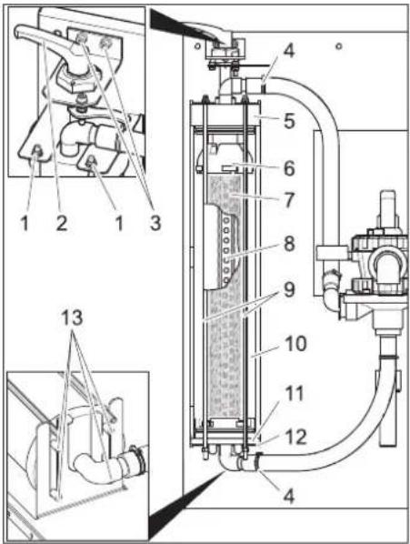
1 Nut
2 Tension lever
3 Screw of the tension lever bearing
4 Hose clip
5 Cover
6 Upper section
7 Filter inlay
8 Filtrate pipe
9 Threaded rod
10 Filament filter
11 Lower part
12 Lower console
13 Pin
→ Unlock filter.
→ Open the hose clamps.
→ Pull the hoses off the hose fittings.
→ Turn out both the screws of the tension lever bearing.
→ Lift upward the entire tension lever along with the bearings.
→ Unscrew the nuts at the upper end of the threaded rods.
→ Remove the threaded rod assembly.
→ Pull out the filament filter towards the front.
→ Remove the lid of the filament filter.
→ Pull out the lower part of the filament filter including filter inlay.
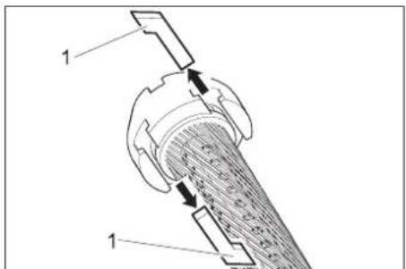
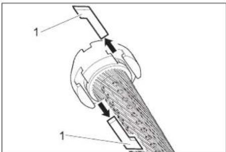
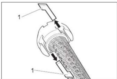
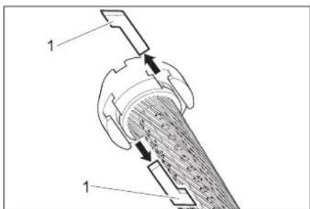
1 Grooved stone
→ Pullout the grooved stones between the upper part and the filter inlay and between the lower part and the filter inlay.
→ Remove upper and lower part of filter inlay.
→ Remove filtrate pipe from filtrate inlay,
→ Dispose of the filter inlay.
→ Attach filtrate pipe at one end of the new filter inlay.
→ Tighten the filter inlay in such a way that the filaments do not twist.
→ Push the filtrate pipe in the filter inlay and by looking at the opposite side of the filter element push the inlay in the direction of the filtrate pipe.
→ Coat all rings with normal liquid soap before carrying out any further installation tasks.
Note
Do not use silicon grease. Silicon in water will hamper the cleaning and drying effect during vehicle wash.
→ Insert the upper and lower part on the filter element.
→ Align the upper and lower part in such a way that the grooved stones can be inserted.
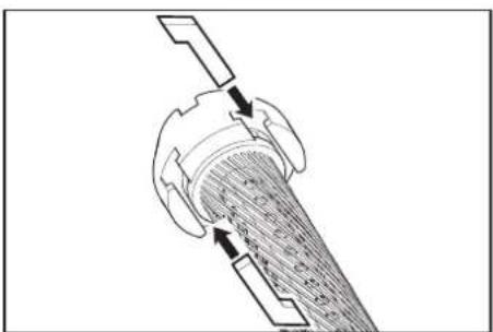
natural_image
Cross-sectional diagram of a mechanical component with internal structure and directional arrows (no text or labels)→ Insert the grooved stones and clamp it tight by slightly turning the filter inlay.
→ Insert the lower part into the filament filter and push it in completely.
→ Replace the filament filter lid.
→ Place the filament filter on the lower console so that both the rear pins lock into the long-holes of the console.

→ Align the lid, as shown above, and push it in completely.
→ Push in the filament filter between the two consoles.
→ Hook in the threaded rod assembly at the lower console and insert the threaded rods through the holes in the upper console.
→ Fasten the threaded rods with undelay washers and nuts.
→ Tighten the nuts in such a way that the underlay washers can be still be moved by hand.
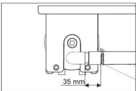
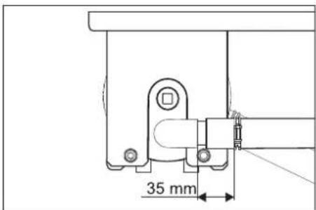
→ Insert the hoses onto the hose fittings.
→ Tighten the hose clamps (keep the 35 mm distance).
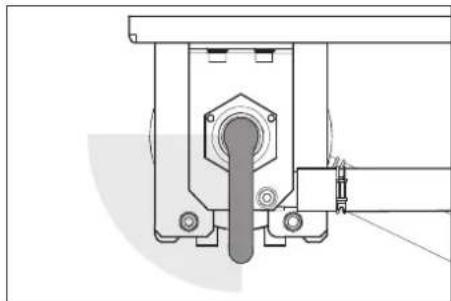
→ Insert the tension lever with bearing through the lid of the filament filter.
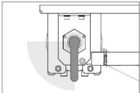
natural_image
Technical line drawing of a mechanical assembly with no visible text or symbols→ Turn the tightening lever in clockwise direction. It should be possible to turn the tightening lever in the range shown above without exerting any pressure. Otherwise, dismantle the tightening lever and insert it again in the correct position.
→ Fasten the tension lever bearings with screws.
→ Adjust the filter pre-tension.
Troubleshooting
⚠ Danger
Risk of accident while working on the unit. During all tasks
→ Switch off the immersion pump in the building.
Who may remedy faults?
- Operator
Work designated with the sign "Operator" may only be carried out by persons who have been instructed in the safe operation and maintenance on the wash plant
- Customer Service
Work designated with the sign "Customer Service" may only be done by the fitters of Kärcher Customer Service or fitters who have been authorised by Kärcher.
| Fault Possible cause | Remedy By whom | ||
| Plant out of order Power supply to the pump in the building is interrupted. | Check power supply and ensure proper supply. Operator | ||
| Processed water is coloured or is foaming too much | Filter pre-tension is not correct. Adjust the filter pre-tension Operator | ||
| Filter inlay is defective (leaky) Replacing filter inlay Operator, Cus- | tomer Service | ||
| Sludge collector or pump basin is dirty Emptying and cleaning the basins Operator/ Dis- | posal agency | ||
| Improper detergents are used in the washing unit or washing hall | Use compatible detergents; rinse the system, if necessary | Operator, Cus-tomer Service | |
| Detergent dosing in the washing unit is too high | Check detergent dosing; reset, if necessary Operator, Cus-tomer Service | ||
| Washing place cleaned with incompatible detergents | Replace water and rinse the basins Operator | ||
| Filter output is too low | Filament filter is blocked | Backwash filament filter; replace filter inlay if required. | Operator |
| Immersion pump is of lesser dimension | Install a suitable immersion pump (see requirements under "Technical Data") | Operator | |
| Immersion pump is blocked, defective | Clean, repair, replace immersion pump | Operator, Cus-tomer Service | |
| Pipe or valve is leaky, defective, blocked | Check pipes and valves; clean, repair or replace as required | Operator, Cus-tomer Service | |
Accessories
Filter inlay
| Order number | 5.033-239.0 |
Attachment set 'Fresh water switching'
| Order number | 2.641-521.0 |
Manual switching between processed/fresh water for using fresh water in the high-pressure cleaner (for e.g. for rinsing).
Installing the unit (only for experts)
Notice
The equipment may only be installed by an
- mechanic of Kärcher
– or an from Kärcher authorized individual
Preparing the installation place
The following requirements are necessary in order to install the equipment:
- frost-free room with adequate ventilation and exhausts
– Floor path for collecting sludge
– Strong wall for fastening the system
Unpack the equipment
Unpack the equipment and dispose of the packing material properly.
Water installation
The water installation depends on the specific conditions of the existing plant components such as
- Type and model of high-pressure cleaner or washing system
Note
The processed water outlet of the system is directly connected to the water inlet of the high-pressure cleaner. This can lead to foam formation in the swimmer tank in high-pressure cleaners with a swimmer tank. In such a case, the high-pressure cleaner must be switched to suction operations (see separate operating instructions of the high-pressure cleaner).
- Type and models of building-side components (sludge collector, pump basin, etc.)
– Nominal widtht, lengths and type of channels
Hence, the water installation must be done according to the specific local conditions. The immersion pump specifications in the building must meet the requirements outline in the "Technical Data / Immersion Pump Requirements" section.
⚠️Danger
Risk of injury on account of tripping and falling. Lay the hoses of the plant in such a way that they do not pose a risk for tripping and falling.
www.kaercher.com/REACH
Garantie
1 Levier de serrage
1 Coulisseau
natural_image
Cross-sectional diagram of a mechanical component with internal structure and directional arrows (no text or labels)natural_image
Technical line drawing of a mechanical assembly with no visible text or symbols1 Dado
1 Dado scanalato
natural_image
Technical diagram of a mechanical component with internal structure and directional arrows (no text or labels)natural_image
Technical line drawing of a mechanical assembly with no visible text or symbolswww.kaercher.com/REACH
Garantie
1 Spanhefboom
2 Ontgrendelhefboom
3 Manometer Filteringang
4 Meerwegventiel
5 Draadfilter
6 Overstroomklep
1 Moer
2 Spanhefboom
3 Schroef lagering spanhefboom
4 Slangklem
5 Deksel
6 Bovenste deel
7 Filterelement
8 Filtraatbuis
1 T-moer
natural_image
Diagram of a mechanical component with internal structure and directional arrows (no text or symbols)natural_image
Technical line drawing of a mechanical assembly with no visible text or symbolswww.kaercher.com/REACH
Garantía
1 tuerca
1 Tuerca deslizante
natural_image
Cross-sectional diagram of a mechanical component with internal structure and directional arrows (no text or labels)natural_image
Technical line drawing of a mechanical assembly with no visible text or symbolswww.kaercher.com/REACH
Garantia
1 Porca
2 Alavanca de tensionamento
1 Lingueta
natural_image
Cross-sectional diagram of a mechanical component with internal structure and directional arrows (no text or labels)natural_image
Technical line drawing of a mechanical assembly with no visible text or symbolswww.kaercher.com/REACH
Garanti
1 Møtrik
2 Spændehåndtag
1 Notsten
natural_image
Cross-sectional diagram of a mechanical component with internal structure and directional arrows (no text or labels)natural_image
Technical line drawing of a mechanical assembly with no visible text or symbolswww.kaercher.com/REACH
Garanti
1 Spennhendel
2 Låsespake
3 Manometer filteringngang
4 Flerveisventil
5 Filamentfilter
6 Overstrømsventil
A Til slamfangeren (tilbakespyling)
Stille inn filterforspenning
Ved spyling strømmer vannet over:
- Sugepumpe
- Multiventil i stilling "FORFILTRERING/RINSE"
- Filter (flytretning filtere)
- i slamfangeren
SIRKULASJON/RECIRCULATION
1 Mutter
2 Spennhendel
3 Skrue spennhendellager
4 Slangeklemme
5 Deksel
6 Overdel
7 Filterinnsats
8 Filtratrør
9 Gjengebolt
10 Filamentfilter
11 Underdel
12 Nedre konsoll
13 Stift
1 Festeblokk
natural_image
Diagram of a mechanical component with internal structure and directional arrows (no text or symbols)natural_image
Technical line drawing of a mechanical assembly with no visible text or symbolswww.kaercher.com/REACH
Garanti
1 Spännarm
2 Spärrspak
1 Mutter
2 Spännarm
1 Notkloss
natural_image
Diagram of a mechanical component with internal structure and directional arrows (no text or symbols)natural_image
Technical line drawing of a mechanical assembly with no visible text or symbolswww.kaercher.com/REACH
Takuu
1 Mutteri
2 Kiristyskahva
1 T-urakiinnitin
natural_image
Diagram of a mechanical component with internal structure and directional arrows (no text or symbols)natural_image
Technical line drawing of a mechanical assembly with no visible text or symbols1 Μοχλός σύσφιξης
1 Περικόχλιο
2 Μοχλός σύσφιξης
1 Γλωσσίδα
natural_image
Cross-sectional diagram of a mechanical component with internal structure and directional arrows (no text or labels)natural_image
Technical line drawing of a mechanical assembly with no visible text or symbolswww.kaercher.com/REACH
Garanti
1 Gergi kolu
2 Kilit açma kolu
3 Manometre; filtre girişi
4 Çok yollu valf
5 Elyaf filtre
6 T a şma valfı
1 Somun
2 Gergi kolu
3 Gergi kolu yatağının cıvatası
4 Hortum kelepçesi
5 Kapak
6 Üst parça
7 Filtre kartuşu
8 Filtrat borusu
9 D i şli çubuk
10 Elyaf filtre
11 Alt parça
12 Alt konsol
13 Pim
1 Oluk taş
natural_image
Cross-sectional diagram of a mechanical component with internal structure and directional arrows (no text or labels)natural_image
Technical line drawing of a mechanical assembly with no visible text or symbolswww.kaercher.com/REACH
1 Рукоятка зажима
1 Гайка
2 Рукоятка зажима
natural_image
Diagram of a mechanical component with internal structure and directional arrows (no text or symbols)natural_image
Technical line drawing of a mechanical assembly with no visible text or symbolswww.kaercher.com/REACH
Garancia
1 Feszítőkar
2 Kioldókar
1 Anya
2 Feszítőkar
1 Csúszótömb
natural_image
Cross-sectional diagram of a mechanical component with internal structure and directional arrows (no text or labels)natural_image
Technical line drawing of a mechanical assembly with no visible text or symbolswww.kaercher.com/REACH
Záruka
1 Upínací páčka
2 Uvolňovací páka
1 Matice
2 Upínací páčka
1 Vodicí vložka
natural_image
Diagram of a mechanical component with internal structure and directional arrows (no text or symbols)natural_image
Technical line drawing of a mechanical assembly with no visible text or symbols1 Napenjalo
2 R o čica za deblokado
3 Manometer na vhodu filtra
4 V e čpotni ventil
5 Filamentni filter
6 Prelivni ventil
A v lovilnik blata (povratno izpiranje)
1 Matica
2 Napenjalo
3 Vijak ležaja napenjala
4 Objemka za gibko cev
5 Pokrov
6 Zgornji del
7 Filtrni vložek
8 Cev za filtrat
9 Drog z navojem
10 Filamentni filter
11 Spodnji del
12 Spodnja konzola
13 Zatič
→ Sprostite filter.
→ Odprite objemke za gibko cev.
→ Gibke cevi snemite z nastavkov za gibke cevi.
→ Izvijte oba vijaka ležaja napenjala.
→ Napenjalo skupaj z uležajenjem snemite navzgor.
→ Odvijte matice na zgornjem koncu droga z navojem.
→ Snemite sklop droga z navojem.
→ Filamentni filter izvlecite naprej.
→ Snemite pokrov filamentnega filtra.
→ Snemite spodnji del filamentnega filtra skupaj s filtrnim vložkom.
1 Matica vijaka z režo
→ Izvlecite matice vijaka z režo med zgornjim delom in filtrnim vložkom in med spodnjim delom in filtrnim vložkom.
natural_image
Diagram of a mechanical component with internal structure and directional arrows (no text or symbols)→ Vtaknite matice vijaka z režo in prižemite z rahlim obračanjem filtrnega vložka.
→ Spodnji del vstavite v filamentni filter in povsem potisnite notri.
→ Pokrov namestite na filamentni filter.
→ Filamentni filter postavite na spodnjo konzolo, da oba zadnja zatiča sedita v vodoravnih luknjah konzole.

→ Kot prikazano zgoraj, pokrov naravnajte in popolnoma potisnite notri.
→ Filamentni filter potisnite med obe konzoli.
→ Sklop drogov z navojem pritrdite s kavljem na spodnjo konzolo in drogove z navojem vtaknite skozi izvrtine v zgornji konzoli.
→ Drogove z navojem pritrdite s podložkami in maticami.
→ Matice pritegnite tako trdno, da se podložke se lahko premikajo z roko.
→ Gibke cevi nataknite na nastavke za gibke cevi.
→ Pritegnite objemke za gibke cevi (upoštevajte razdaljo 35 mm).
→ Napenjalo z uležajenjem vtaknite skozi pokrov filamentnega filtra.
natural_image
Technical line drawing of a mechanical assembly with no visible text or symbols→ Napenjalo zavrtite v smeri urnega kazalca. Napenjalo mora biti mogoče brez napora obrniti v zgoraj prikazano področje. Sicer demontirajte napenjalo in ponovno vstavite v popravljenem položaju.
→ Ležaj napenjala pritrdite z obemi vijaki.
→ Nastavite prednapetost filtra.
Pomoč pri motnjah
⚠️ Nevarnost
www.kaercher.com/REACH
Gwarancja
1 Nakrętka
1 Kamień ustalający
natural_image
Diagram of a mechanical component with internal structure and directional arrows (no text or symbols)natural_image
Technical line drawing of a mechanical assembly with no visible text or symbolswww.kaercher.com/REACH
Garantie
1 Mâner de tensionare
1 Culisor
natural_image
Technical diagram of a mechanical component with internal structure and directional arrows (no text or labels)natural_image
Technical line drawing of a mechanical assembly with no visible text or symbolswww.kaercher.com/REACH
Záruka
1 Upínacia páka
2 Uvoľňovacia páka
3 Tlakomer na vstupe filtra
4 Viaccestný ventil
5 Filter z vlákien
6 Prepúšt'ací ventil
1 Matica
2 Upínacia páka
1 Vodiaca vložka
natural_image
Diagram of a mechanical component with internal structure and directional arrows (no text or symbols)→ Nasad'te vodiace vložky a upevnite miernym otočením vložky filtra.
→ Spodnú čast' nasad'te do filtra s vlákna-mi a celkom zasuňte.
→ Na filter s vláknami nasad'te veko.
→ Filter s vláknami nasadte na spodnú konzolu tak, aby obidva zadné kolíky zapadli do pozdlžnych otvorov konzoly.

natural_image
Technical line drawing of a mechanical assembly with no visible text or symbolswww.kaercher.com/REACH
Jamstvo
1 Stezna poluga
2 Otkočna poluga
3 Manometar, ulaz filtra
1 Matica
2 Stezna poluga
3 Vijak ležaja stezne poluge
4 Obujmica za crijevo
5 Poklopac
6 Gornji dio
7 Filtarski umetak
8 Cijev za filtrat
9 Navojna šipka
10 Vlaknasti filtar
11 Donji dio
12 Donja konzola
13 Zatik
→ Otpustite filtar.
→ Otvorite obujmice za crijevo.
→ Skinite crijeva s crijevnih priključaka.
→ Odvijte oba vijka ležaja stezne poluge.
→ Steznu polugu zajedno s ležištem skini-te prema gore.
→ Odvijte matice na gornjem kraju navojne šipke.
→ Skinite sklop navojnih šipki.
→ Izvucite vlaknasti filtar prema naprijed.
→ Skinite poklopac vlaknastog filtra.
→ Skinte donji dio vlaknastog filtra zajedno s filtarskim uloškom.
1 Element s utorima
natural_image
Diagram of a mechanical component with internal structure and directional arrows (no text or symbols)→ Umetnite elemente s utorima i laganim okretanjem učvrstite filtarski uložak.
→ Donji dio postavite u vlaknasti filtar i potpuno ugurajte.
→ Postavite poklopac na vlaknati filtar.
→ Vlaknasti filtar postavite na donju konzolu tako da oba stražnja zatika sjednu u uzdužne rupe konzole.

→ Poklopac centrirajte kako je prikazano gore i potpuno ugurajte.
→ Vlaknasti filtar gurnite između obje konzole.
→ Sklop s navojnim šipkama zakačite na donju konzolu i umetnite navojne šipke kroz provrte u gornjoj konzoli.
→ Navojne šipke učvrstite podloškama i maticama.
→ Matice pritegnite samo toliko da se podloške još mogu pomicati rukom.
→ Priključite crijeva na priključke za crijeva.
→ Pritegnite obujmice za crijeva (održavajte razmak od 35 mm).
→ Kroz poklopac vlaknastog filtra postavite steznu polugu s ležištem.

natural_image
Technical line drawing of a mechanical assembly with no visible text or symbols→ Steznu polugu okrenite u smjeru kazaljke na satu. Stezna poluga mora se moći okretati bez primjene sile u gore prikazanom području. U suprotnom, demontirajte steznu polugu i još jednom je postavite u ispravljeni položaj.
→ Pomoću oba vijka učvrstite ležaj stezne poluge.
→ Podesite prednapetost filtra.
Pomoć u slučaju smetnji
⚠️ Opasnost
Opasnost od ozljeda pri radovima na stroju. Kod svih radova
www.kaercher.com/REACH
Garancija
U svakoj zemlji važe garantni uslovi koje je izdala naša nadležna distributivna organizacija. Eventualne smetnje na uređaju za vreme trajanja garancije otklanjamo besplatno, ukoliko je uzrok greška u materijalu ili proizvodnji. U slučaju koji podleže garanciji obratite se sa potvrdom o kupovini Vašem prodavcu ili najbližoj ovlašćenoj servisnoj službi.
Sigurnosne napomene
Simboli u uputstvu za rad
1 Do rezervoara reciklirane vode
2 Otkočna poluga
3 Manometar, ulaz filtera
4 Ventil više puteva
5 Filamentni filter
6 Prelivni ventil
A ka odmuljivaču (povratno ispiranje)
B ka visokopritisnom uređaju za čišćenje / rezervoaru za potrošnu vodu (punjenje)
C od potopne pumpe
Podešavanje predzategnutosti filtera
Za naknadno podešavanje zategnutosti filtera postupite na sledeći način:
→ Zateznu ručicu okrenite ulevo do kraja.
→ Povucite otkočnu polugu prema i zateznu ručicu okrenite udesno dok se otkočna poluga ne uglavi u sledeću rezu.
Pogon filtra
→ Polugu višeputnog ventila okrenuti na položaj „FILTRIRANJE“.
Napomena
Nakon dužeg stajanja uređaja je za aktiviranje račvastog ventila potrebno primeniti veću silu.
1 Navrtka
2 Do rezervoara reciklirane vode
3 Vijak za ležaj tenzione poluge
4 Obujmica za crevo
5 Poklopac
6 Gornji deo
7 Filterski uložak
8 Filterska cev
9 Navojna šipka
10 Filamentni filter
11 Donji deo
12 Donja konzola
13 Klin
→ Filter olabaviti.
→ Otvoriti obujmicu za crevo.
→ Creva izvući iz cevnih spojnica.
→ Oba vijka ležaja tenzione poluge odvrnuti.
→ Tenzionu polugu zajedno sa ležajem skinuti prema gore.
→ Matice na gornjem kraju navojnih šipki odviti.
→ Skinuti navojne šipke-sklopove.
→ Filamentni filter izvući prema napred.
→ Poklopac filamentnog filtera skinuti.
→ Donji deo filamentnog filtera zajedno sa filterskim uložkom skinuti.
1 Kameni žlebovi
→ Izvucite kamene žlebove između gornjeg dela i filterskog uloška i između donjeg dela i filterskog uloška.
→ Skinuti gornji deo i donji deo od filterskog uloška.
→ Izvucite filtersku cev iz filterskog uloška,
→ filterski uložak ukloniti.
→ Postaviti filtersku cev na kraju novog filterskog uloška.
→ Filterski uložak tako napeti, da filamenti nisu uvrnuti.
→ Filtersku cev gurnuti u filterski uložak i pri tome kroz pogled na suprotnu stranu filterskog elementa upravljati smer filterske cevi.
→ Pred daljnjom montažom sve O-prstene premažite sa uobičajenim tekućim sapunom.
Napomena
Ne upotrebljavati silikonsku mast. Silikon u vodi umanjuje rezultat čiščenja i sušenja kod pranja vozila.
natural_image
Diagram of a mechanical component with internal structure and directional arrows (no text or symbols)→ Kamene žlebove umetnuti i pritegnuti sa laganim okretanjem filterskog uloška.
→ Donji deo postaviti u filamentni filter i potpuno gurnuti.
→ Poklopac postaviti na filamentni filter.
→ Filamentni filter staviti na donju konzolu, da oba zadnja klipa budu u dugim rupama konzole.
→ Poklopac, kao što je gore prikazan, ispraviti i potpuno gurnuti.
→ Filamentni filter gurnuti između obe konzole.
→ Navojne šipke-sklopove na donju konzolu obesiti i navojne šipke utaknuti kroz otvore u gornjem delu konzole.
→ Navojne šipke pričvrstiti sa podloškama i maticama.
→ Matice pritegnuti tako čvrsto, da se podloške još mogu sa rukom pomeriti.
→ Utaknuti crevo na crevni priključak.
→ Pričvrstiti obujmice (Rastojanje 35 mm zadržati).
→ Tenzionu polugu sa ležajem gurnuti kroz poklopac filamentnog filtera.

natural_image
Technical line drawing of a mechanical assembly with no visible text or symbols→ Tenzionu polugu okrenuti u smeru kazaljke na satu. Tenziona poluga mora se okretati bez teškoća u gore pokazano područje. U suprotnom tenzionu polugu demonitirati i ponovo staviti u ispravnom položaju.
→ Ležaj tenzione poluge pričvrstiti sa oba vijka.
→ Prednapetost filtra podesiti.
Pomoć u slučaju smetnji
⚠️ Opasnost
Opasnost od nesreće kod radova na uređaju. Kod svih radova
→ Odložite postojeću potopnu pumpu.
Ko sme ukloniti smetnje?
– Vlasnik/koncesionar
www.kaercher.com/REACH
Гаранция
1 Затегателен лост
2 Деблокиращ лост
1 Гайка
2 Затегателен лост
1 Монтажна шпонка
natural_image
Diagram of a mechanical component with internal structure and directional arrows (no text or symbols)natural_image
Technical line drawing of a mechanical assembly with no visible text or symbolswww.kaercher.com/REACH
Garantii
1 Kinnitushoob
2 Vabastushoob
1 Mutter
2 Kinnitushoob
3 Kinnitushoova laagri kruvi
4 Voolikumansett
5 Kaas
6 Ülemine osa
7 Filtripadrun
8 Filtraattoru
9 Keermestatud varb
10 Filamentfilter
11 Alumine osa
12 Alumine konsool
13 Tihvt
1 Liugplokk
natural_image
Diagram of a mechanical component with internal structure and directional arrows (no text or symbols)→ Torgake liugplokid kohale ja kinnitage filtripadrunit pisut keerates.
→ Pange alumine osa filamentfiltrisse ja lükake löpuni sisse.
→ Pange kaas filamentfiltrile.
→ Pange filamentfilter alumisele konsooliile, nii et mölemad tagumised tihvtid oleksid konsooli pikergustes aukudes.
natural_image
Technical line drawing of a mechanical assembly with no visible text or symbolswww.kaercher.com/REACH
Garantija
1 Sprüdtapa
natural_image
Diagram of a mechanical component with internal structure and directional arrows (no text or symbols)natural_image
Technical line drawing of a mechanical assembly with no visible text or symbolswww.kaercher.com/REACH
Garantija
1 ltempimo svirtis
2 Atblokavimo svirtis
1 lkaišas
natural_image
Diagram of a mechanical component with internal structure and directional arrows (no text or symbols)natural_image
Technical line drawing of a mechanical assembly with no visible text or symbolsnatural_image
Diagram of a mechanical component with internal structure and directional arrows (no text or symbols)natural_image
Technical line drawing of a mechanical assembly with no visible text or symbolsnatural_image
Black silhouette of a hand giving a thumbs-up gesture (no text or symbols)THANK YOU!
MERCI! DANKE! iGRACIAS!
Registrieren Sie Ihr Produkt und profitieren Sie von vielen Vorteilen. Register your product and benefit from many advantages. Enregistrez votre produit et bénéficier de nombreux avantages. Registre su producto y aproveche de muchas ventajas.
www.kaercher.com/welcome

Bewerten Sie Ihr Produkt und sagen Sie uns Ihre Meinung. Rate your product and tell us your opinion. Évaluer votre produit et dites-nous votre opinion. Reseñe su producto y díganos su opinión.

natural_image
Icon showing a gear and wrench, no text or symbols presentwww.kaercher.com/dealersearch
Alfred Kärcher SE & Co. KG
Alfred-Kärcher-Str. 28-40
71364 Winnenden (Germany)
Tel.: +49 7195 14-0
Fax: +49 7195 14-2212