HDS 950 De Tr1 - Pressure washer Kärcher - Free user manual and instructions
Find the device manual for free HDS 950 De Tr1 Kärcher in PDF.
User questions about HDS 950 De Tr1 Kärcher
0 question about this device. Answer the ones you know or ask your own.
Ask a new question about this device
Download the instructions for your Pressure washer in PDF format for free! Find your manual HDS 950 De Tr1 - Kärcher and take your electronic device back in hand. On this page are published all the documents necessary for the use of your device. HDS 950 De Tr1 by Kärcher.
USER MANUAL HDS 950 De Tr1 Kärcher
HDS 9/50 DeTr1
HDS 13/35 DeTr1
HDS 13/20 DeTr1
HDS 17/20 DeTr1
| Deutsch 2 | |
| English 16 | |
| Français 31 | |
| Italiano 45 | |
| Espanol 59 | |
| Portugués 74 | |
| Nederlandes 89 | |
| Türkce 103 | |
| Svenska 117 | |
| Suomi 131 | |
| Norsk 145 | |
| Dansk 159 | |
| Eesti 173 | |
| Latviešu 187 | |
| Lietuviskai 201 | |
| Polski 215 | |
| Magyar 229 | |
| Čestina | 243 |
| Slovenčina | 257 |
| Slovenskina | 271 |
| Româna | 285 |
| Hrvatski | 300 |
| Srpski 314 | |
| Еλλυκá | 328 |
| Pyccský | 343 |
| Урочи隸砲а | 359 |
| Блларску | 374 |
| Казakша | 389 |
| „şaj" | 404 |
Inhalt
Bedienfeld

0/OFF = Aus
HD 9/23 GeTr1 + HD 9/23 DeTr1
Gemessen: 105
Garantiert: 107
HDS 13/20 DeTr1
Gemessen: 97
Garantiert: 100
HDS 13/35 DeTr1 + HDS 9/50 DeTr1
Gemessen: 100
Garantiert: 102
HDS 17/20 DeTr1
Gemessen: 100
Garantiert: 102
OPTIONAL

H. Jenner
Chairman of the Board of Management
S. Reiser
Manager Regulatory Affairs & Certification
71364 Winnenden (Germany)
Tel.: +49 7195 14-0
Fax: +49 7195 14-2212
Winnenden, 2023/01/01
Technische Daten
HDS 9/50 DE Tr1 HDS 13/35 DE Tr1 HDS 13/20 DE Tr1 HDS 17/20 DE Tr1
Wasseranschluss
Zulauftemperatur (max.) ^ C30303030
Zulaufmenge (min.) l/h (l/min) 1000 (16,7) 1500 (25) 1500 (25) 1800 (30)
Zulaufdruck (max.) MPa bar 0,05-1 (0,5-10) 0,1-1 (1-10) 0,1-1 (1-10) 0,15-1 (1,5-10)
Environmental protection 16
Symbols on the device. 16
Intended use 16
Safety instructions 16
Function 16
Safety devices 16
Device overview 17
Initial startup 19
Operation 20
Transport 22
Storage 22
Care and service 23
Troubleshooting guide 26
Warranty 28
Accessories and spare parts 28
Declaration of Conformity 29
Technical data 30
General notes
Read these original operating instruc
tions before using your device for the
first time, follow them accord keep them for later use or for future owners.
- Notify the dealer immediately in the case of shipping damage.
- Check package content when unpacking.
- Be sure to read the safety instructions no. 5.951-949.0 prior to the initial startup!
Environmental protection

The packing materials can be recycled. Please
dispose of packaging in accordance with the environmental regulations.

Electrical and electronic devices contain valu
ble, recyclable materials and often components
such as batteries, rechargeable batteries or oil ,which is handled operationally of incorrectly . 00
which - if handled or disposed of incorrectly - can pose a potential danger to human health and the environment. However, these components are required for the correct operation of the device. Devices marked by this symbol are not allowed to be disposed of together with the household rubbish.
Notes on the content materials (REACH)
Current information on content materials can be found at: www.kaercher.de/REACH
Supplementary environmental protection
instructions
Please do not allow engine oil, heating oil, diesel and petrol to enter the environment. Please protect the ground and dispose of old oil in an environmentally friendly manner.
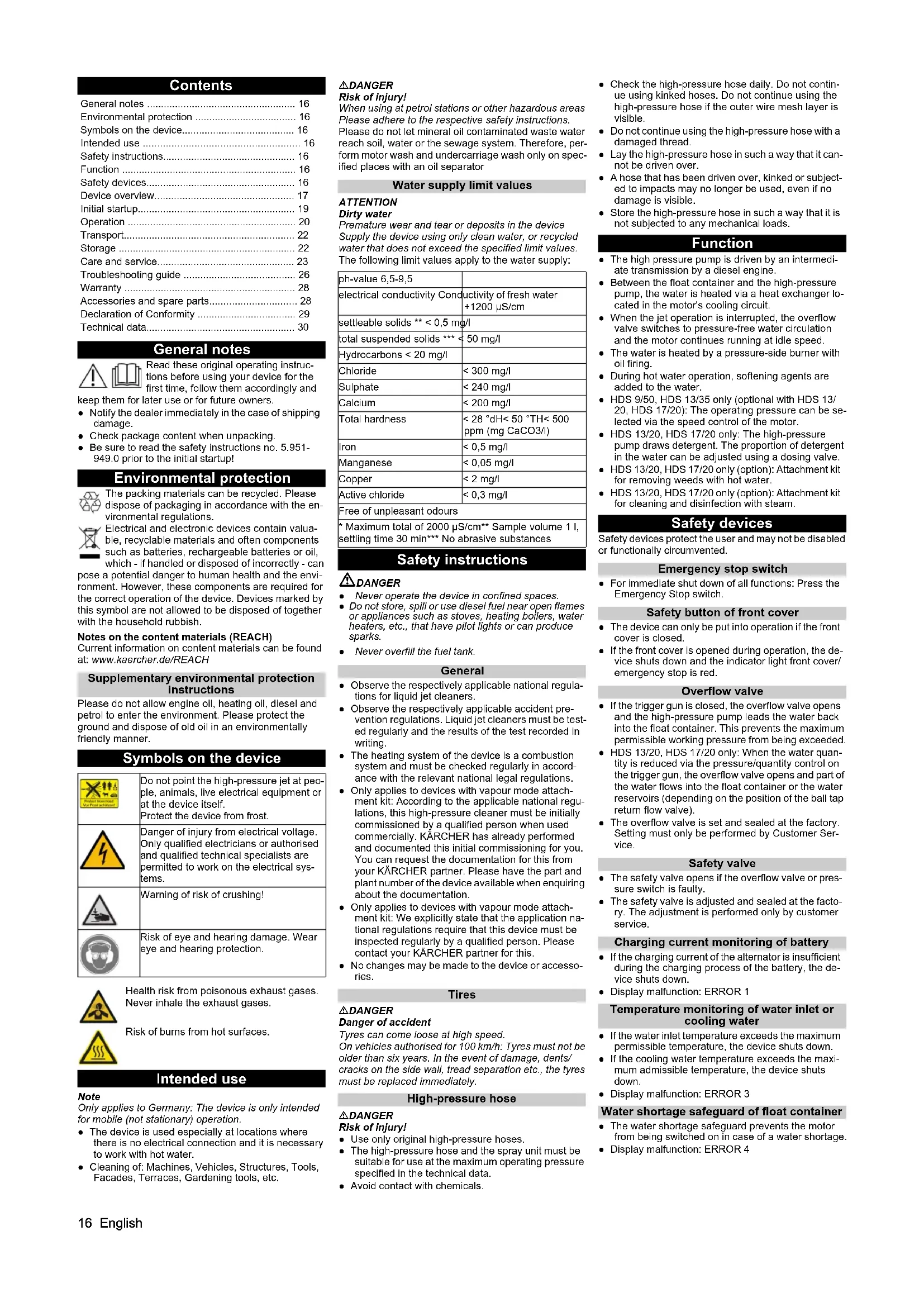
Symbols on the device

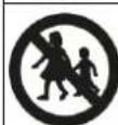
Do not point the high-pressure jet at peo
ple, animals, live electrical equipment or at the device itself.
Protect the device from frost.

Danger of injury from electrical voltage.
Only qualified electricians or authorised
and qualified technical specialists are
permitted to work on the electrical systems.

Warning of risk of crushing!

Risk of eye and hearing damage. Wear
eye and hearing protection.

Health risk from poisonous exhaust gases.
Never inhale the exhaust gases.
Risk of burns from hot surfaces.
Intended use
Note
Only applies to Germany: The device is only intended for mobile (not stationary) operation.
- The device is used especially at locations where there is no electrical connection and it is necessary to work with hot water.
- Cleaning of: Machines, Vehicles, Structures, Tools, Facades, Terraces, Gardening tools, etc.
△DANGER
Risk of Injury!
When using at petrol stations or other hazardous areas Please adhere to the respective safety instructions.
Please do not let mineral oil contaminated waste water
reach soil, water or the sewage system. Therefore, per
form motor wash and undercarriage wash only on specified places with an oil separator
Water supply limit values
ATTENTION
Dirty water
Premature wear and tear or deposits in the device
Supply the device using only clean water, or recycled
water that does not exceed the specified limit values.
The following limit values apply to the water supply:
| ph-value 6,5-9,5 | |
| electrical conductivity Conductivity of fresh water +1200 μS/cm | |
| settleable solids ** < 0,5 mg/l | |
| total suspended solids *** < 50 mg/l | |
| Hydrocarbons < 20 mg/l | |
| Chloride | < 300 mg/l |
| Sulphate | < 240 mg/l |
| Calcium | < 200 mg/l |
| Total hardness | < 28 °dH< 50 °TH< 500 ppm (mg CaCO3/l) |
| Iron | < 0,5 mg/l |
| Manganese | < 0,05 mg/l |
| Copper | < 2 mg/l |
| Active chloride | < 0,3 mg/l |
Free of unpleasant odours
- Maximum total of 200 μs/cm Sample volume 1 L, settling time 30 min* No abrasive substances
Safety instructions
DANGER
- Never operate the device in confined spaces.
- Do not store, spill or use diesel fuel near open flames or appliances such as stoves, heating boilers, water heaters, etc., that have pilot lights or can produce sparks.
- Never overfill the fuel tank.
General
- Observe the respectively applicable national regulations for liquid jet cleaners.
- Observe the respectively applicable accident prevention regulations. Liquid jet cleaners must be tested regularly and the results of the test recorded in writing.
- The heating system of the device is a combustion system and must be checked regularly in accordance with the relevant national legal regulations.
- Only applies to devices with vapour mode attachment kit: According to the applicable national regulations, this high-pressure cleaner must be initially commissioned by a qualified person when used commercially. KARCHER has already performed and documented this initial commissioning for you. You can request the documentation for this from your KARCHER partner. Please have the part and plant number of the device available when enquiring about the documentation.
- Only applies to devices with vapour mode attachment kit: We explicitly state that the application national regulations require that this device must be inspected regularly by a qualified person. Please contact your KÄRCHER partner for this.
- No changes may be made to the device or accessories.
Tires
△DANGER
Danger of accident
Tyres can come loose at high speed.
On vehicles authorised for 100km/h Tyres must not be
older than six years. In the event of damage, dents/
cracks on the side wall, tread separation etc., the tyres must be replaced immediately.
High-pressure hose
△DANGER
Risk of injury!
- Use only original high-pressure hoses.
- The high-pressure hose and the spray unit must be suitable for use at the maximum operating pressure specified in the technical data.
-
Avoid contact with chemicals.
-
Check the high-pressure hose daily. Do not continue using kinked hoses. Do not continue using the high-pressure hose if the outer wire mesh layer is visible.
- Do not continue using the high-pressure hose with a damaged thread.
- Lay the high-pressure hose in such a way that it cannot be driven over.
- A hose that has been driven over, kinked or subjected to impacts may no longer be used, even if no damage is visible.
- Store the high-pressure hose in such a way that it is not subjected to any mechanical loads.
Function
The high pressure pump is driven by an intermediate transmission by a diesel engine.
- Between the float container and the high-pressure pump, the water is heated via a heat exchanger located in the motor's cooling circuit.
- When the jet operation is interrupted, the overflow valve switches to pressure-free water circulation and the motor continues running at idle speed.
- The water is heated by a pressure-side burner with oil firing.
- During hot water operation, softening agents are added to the water.
- HDS 9/50, HDS 13/35 only (optional with HDS 13/20, HDS 17/20): The operating pressure can be selected via the speed control of the motor.
HDS 13/20, HDS 17/20 only: The high-pressure pump draws detergent. The proportion of detergent in the water can be adjusted using a dosing valve.
HDS 13/20, HDS 17/20 only (option): Attachment kit for removing weeds with hot water.
HDS 13/20, HDS 17/20 only (option): Attachment kit for cleaning and disinfection with steam.
Safety devices
Safety devices protect the user and may not be disabled or functionally circumvented.
Emergency stop switch
For immediate shut down of all functions: Press the Emergency Stop switch.
Safety button of front cover
- The device can only be put into operation if the front cover is closed.
If the front cover is opened during operation, the device shuts down and the indicator light front cover/ emergency stop is red.
Overflow valve
- If the trigger gun is closed, the overflow valve opens and the high-pressure pump leads the water back into the float container. This prevents the maximum permissible working pressure from being exceeded
HDS 13/20, HDS 17/20 only: When the water quantity is reduced via the pressure/quantity control on the trigger gun, the overflow valve opens and part of the water flows into the float container or the water reservoirs (depending on the position of the ball tap return flow valve). - The overflow valve is set and sealed at the factory. Setting must only be performed by Customer Service.
Safety valve
- The safety valve opens if the overflow valve or pressure switch is faulty.
- The safety valve is adjusted and sealed at the factory. The adjustment is performed only by customer service.
Charging current monitoring of battery
- If the charging current of the alternator is insufficient during the charging process of the battery, the device shuts down.
- Display malfunction: ERROR 1
Temperature monitoring of water inlet or
cooling water
- If the water inlet temperature exceeds the maximum permissible temperature, the device shuts down.
- If the cooling water temperature exceeds the maximum admissible temperature, the device shuts down.
- Display malfunction: ERROR 3
Water shortage safeguard of float container
The water shortage safeguard prevents the motor from being switched on in case of a water shortage
- Display malfunction: ERROR 4
Water shortage safeguard of burner
- The water shortage safeguard (flow switch) prevents the burner from overheating in the case of a shortage of water. The burner operates only when there is adequate water supply.
- Display malfunction: ERROR 5
Pressure switch/flow switch
- The combination pressure switch/flow switch shuts down the device in case of water shortage or leakage.
- Display malfunction: ERROR 5
Fill level monitoring of fuel
The device shuts down in the event of a fuel shortage (fuel tank empty).
Note
The device can be operated for another 5 minutes until the fuel tank is completely empty by switching the device off and then on again.
- The device shuts down if the fuel sensor is defective.
Display malfunction:ERROR 6
Engine oil pressure
- The pressure switch turns off the motor when the minimum engine oil pressure is not maintained.
- Display malfunction: ERROR 7
Exhaust gas thermostat
- The exhaust gas thermostat switches off the burner when the exhaust gas temperature is too high.
- Display malfunction: ERROR 9
Temperature monitoring of burner
-
If the water temperature at the burner outlet exceeds the maximum admissible temperature, the device switches off the burner.
The device switches off the burner if the temperature sensor is defective. -
Display malfunction: ERROR 10
Flame monitoring
- The flame monitoring switches off the burner in case of a burner fault.
- Display malfunction: ERROR 11 or 12
Switch off after expiry of standby time or after continuous operation
- If the standby time or the continuous operation time of 45 minutes is exceeded, the electronics switch the device off (factory setting).
- Display malfunction: ERROR 14 or 15
Safety latch
The safety latch on the trigger gun prevents the device from being switched on unintentionally.
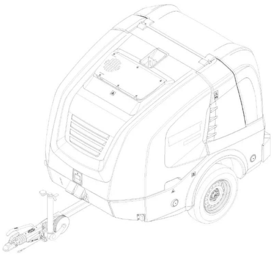
Device overview
Description of the device
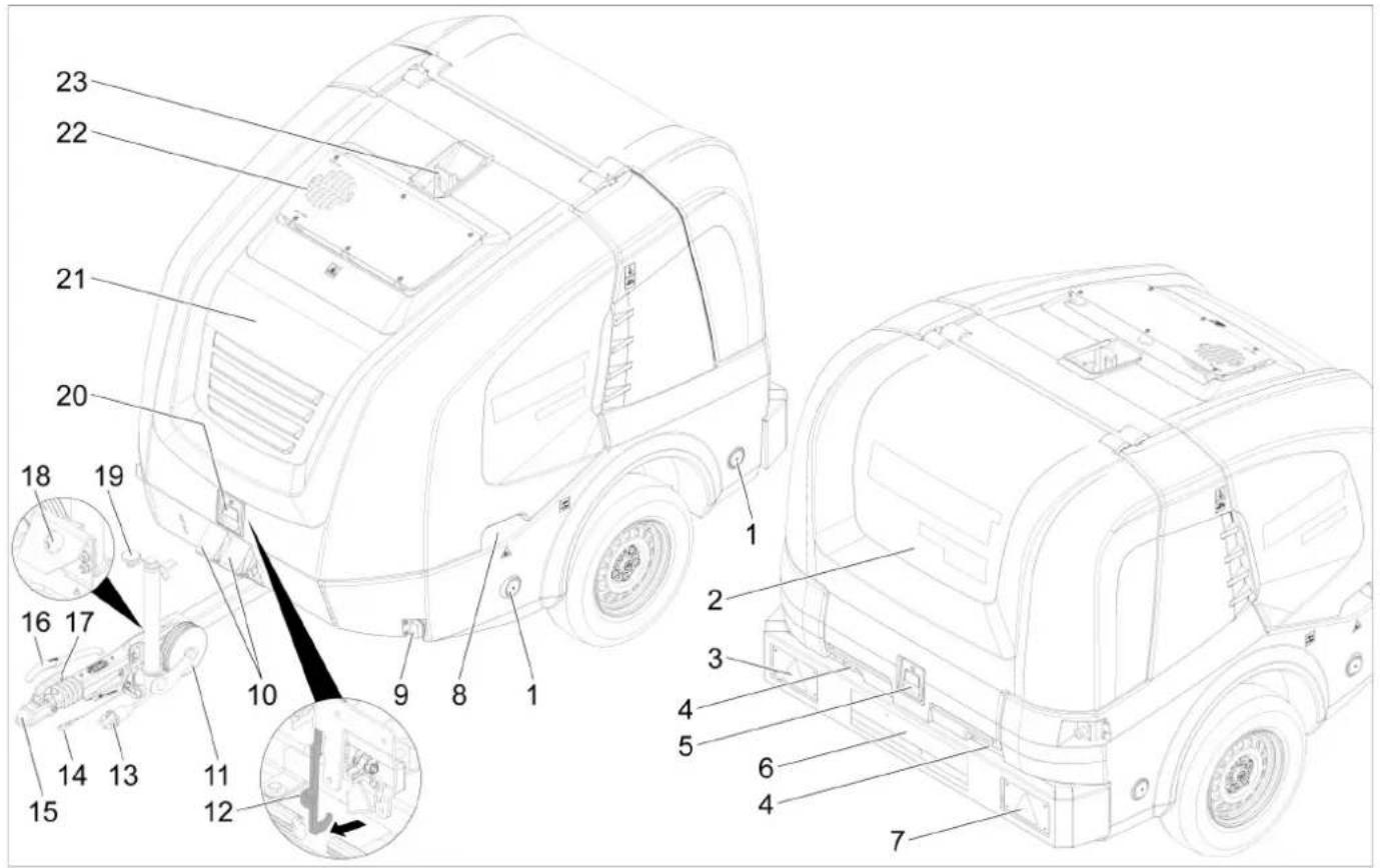
① Reflector (on both sides)
(2) Rear cover
Combined brake/tail light with direction indicator (left)
4Hose inlet with closed rear cover
(5)Lock of rear cover
(6)Licence plate with licence plate lights
Combined brake/tail light with direction indicator (right)
(8) Recessed grip of the front cover (on both sides)
(9)Marker light (on both sides)
10 Chock
①Support wheel
12 Hooks
13Vehicle lighting plug connection
(14)Safety rope
⑤Tow bar
(6) Parking brake
⑦ Coupling lever
18Holder for vehicle lighting plug connection
19Supporting wheel crank
20Lock of front cover
(2)Front cover
(22) Exhaust opening
23Lifting eyelet


①Diesel engine
(2)intermediate transmission
③ High-pressure pump
(4) Safety block of burner
Exhaust pipe
(6) Equalising reservoir of motor coolant
7 Maintenance opening of water tank (left)
(8)Air filter
Type plate
Battery
Vehicle identification number
(2)Burner blower
(3) Fuel pump
(4)Booster heater
(5)Ignition transformer
16 Maintenance opening of water reservoir (right)
(17) Detergent container
(18)Filter at the detergent suction hose
(19) Detergent suction hose with level sensor
Detergent dosing valve
Storage compartment for trigger gun
(2)Storage compartment for spray lance
3High-pressure hose
2 High pressure hose reel
25Emergency stop switch
26Low-pressure hose reel
Liquid softener container
(28)Antifreeze container
29Filling nozzle of fuel tank with sieve
30Frost protection ball tap
31Filling level indicator of water reservoirs
32Float container
33)Speed control
34 Filling hole of float container with cover/wing screw
(35)Filling hole for liquid softner
36Ball tap of return switchover
(37)Switch box
38Cover plate (right)
39Cover plate (left)
Supply tap of water reservoirs
41)Drain tap
(42)Frost protection hose
43Water hose
4Water inlet filter
45Pressure gauge
Supply frost protection or parking position for GEKA low-pressure connection
47 Return flow frost protection or parking position for high-pressure connection
48Tank cap
49Control panel
Control panel

0/OFF = off
①Display
(2)Power switch
(3)Indicator light of preheating (red)
4indicator light of standby mode (red)
(5)Key-operated switch
(6) Weed Removal V2.0 operating mode (optional with HDS 13/20, HDS 17/20)
⑦ indicator light of front cover/emergency stop (red)
Cold/warm water operating mode (0-100 °C)
9Frost protection operating mode
10Weed removal operating mode V3.0 & V5.0 or Steam mode operating mode (optional with HDS 13/20, HDS 17/20)
Authorisation documents
The authorisation documents for the device are stored in the electrical device cabinet. The cabinet is locked for transport.
Normal operation display

① Fuel tank (bargraph)
② Motor on (ON) or motor off (OFF)
Liquid softener tank RM110/detergent tank CHEM (OK/empty)
4Operating hours counter
(5)Operating hours until next service
Note
The display of the detergent tank is only present if the detergent tank has been detected as full once before. In normal operation, the controller display alternates between the following displays:
Normal operation
Service: Due service tasks to be performed by the customer service (see care and service).
If multiple maintenance work is due, these are displayed one after another.
This display is not shown if no maintenance work is due.
- Fault: Malfunction occurred (see Troubleshooting). If several faults have occurred, these are displayed one after another.
This display is not shown if no faults are present.
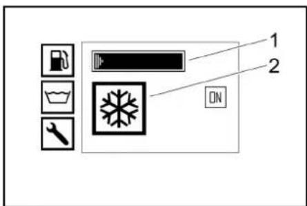
Frost protection display
① Fuel tank (bargraph)
(2)Frost protection operating mode
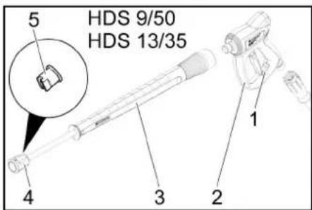
High-pressure gun
(1) Safely latch of the high-pressure gun
② High-pressure gun
③Spray lance
(4) Union nut
High-pressure nozzle

① Safety latch of the high-pressure gun
②EASY!Force high-pressure gun
③EASY!Lock spray lance
4EASY!Lockunionnut
(5)High-pressure nozzle
6Pressure/quantity regulator on the high-pressure gun
⑦ Safety lever
(8) Trigger
Initial startup
WARNING
Risk of injury!
Appliance, accessories, supply lines and connections must be in fault-free condition.
If they are not in a perfect condition, the device must not be used.
Set up and align device
ATTENTION
Overheating of the device
Avoid overheating the device.
Ensure that the installation site is sufficiently ventilated.
Risk of malfunctions and damage to the device.
The device must be in a horizontal position during operation.
- Choose the installation site in a way that the exhaust gas opening is not covered.
- Lock parking brake.
- Lower the support wheel by means of the crank.
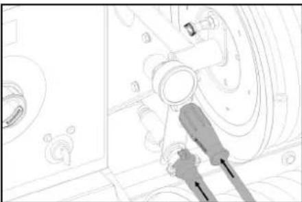
- Remove the tear-off rope from the towing vehicle.
- Disconnect the socket plug connection from the vehicle lighting and insert it into the plug storage on the drawbar.
- Secure the device with wheel chocks to prevent it from rolling away.
- Disconnect the towing vehicle.
- Align the device level using the support wheel.
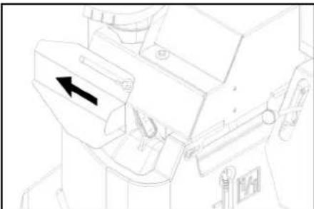
Open/close the front cover
- Actuate the front cover lock.
Front cover opens slightly. - Release the hook catch by pulling it out. The front cover is swung up automatically. When closing, make sure the hook catch engages.
Motor
- Check the oil level of the motor. Do not start up the device if the oil level is below the "MIN" mark.
- Top up with oil if necessary. (see Care and service)
Intermediate transmission
- Check the oil level at the oil-level gauge of the intermediate gearbox.
- Top up with oil if necessary. (see Care and service)
High-pressure pump
- Check the oil level on the oil tank or the oil dipstick of the high-pressure pump.
- Top up with oil if necessary. (see Care and service)
Coolant
- Check the fill level of the coolant in the equalisation container of the motor coolant with a cooled off motor. The fluid level has to be between MIN and MAX.
- Top up with coolant if necessary. (see Care and service)
- Check the antifreeze concentration in the expansion tank.
- Top up with antifreeze if necessary. (see Care and service)
Air filter
-
Check the air filter.
-
Clean/replace the air filter if necessary. (see Care and service)
Filling up the liquid softener
- The liquid softener highly effectively prevents the calcification of the heating coil during operation with hard tap water. This is drip-fed dosed into the float container.
- The dosage is set to medium water hardness at the factory.
Note
A test container of liquid softener is included in the scope of delivery.
- Open filling hole for liquid softener.
- Fill up the liquid softener.
- Close filling hole for liquid softener
Refuelling
△DANGER
Unsuitable fuel
Risk of explosion
Only use diesel fuel or light heating oil. Unsuitable fuels, such as petrol, must not be used.
Note
When biodiesel B5 (as per EN 14214 - European Standard) is used, no special operating, service and maintenance conditions need to be observed.
Note
When biodiesel B6 to B20 (as per EN 14214 - European Standard) is used, modification measures of the diesel engine are required. Moreover, special operating, service and maintenance conditions must be observed. Please contact an authorised Yanmar dealer.
- Open the tank cap.
- Fill in diesel fuel via the filling nozzle of the fuel tank.
- Close the tank cap
- Wipe away spilled diesel fuel.
Refilling detergent
HDS 13/20, HDS 17/20 only:
DANGER
Unsuitable detergents
Risk of injury
Use only KARCHER products.
Never fill with solvents (e.g. petrol, acetone, thinners).
Avoid contact with eyes and skin.
Observe the safety and handling instructions of the detergent manufacturer.
Note
Karcher offers an individual range of cleaning and care products. Your dealer will be happy to advise you.
- Refill/replace the detergent.
Battery
Note
As standard, the device is equipped with a maintenance-free battery.
Safety instructions for the batteries
Be sure to observe the following warnings when handling the batteries:

Observe the notes on the battery, in the instructions and in the vehicle operating instructions!

Wear eye protection!
Keep acids and batteries away from children.
Risk of explosion!
Fire, sparks, open flames and smoking are prohibited!
Risk of acid burns!

First aid!
Warning note!

Disposal!
Do not throw batteries in the bin!
Do not throw batteries in the bin!
DANGER
Risk of explosion!
Do not place tools or similar items on the battery. Short-circuit and risk of explosion.
WARNING
Risk of poisoning!
Never bring wounds into contact with lead. Always clean your hands after working on batteries.
WARNING
Risk of acid burns!
Wear acid-resistant safety goggles, gloves and apron
Charging the battery
△DANGER
Risk of injury!
Observe the safety regulations when handling batteries and the instruction manual of the charger manufacturer
Only charge the battery using a suitable charger.
1. Disconnect the battery.
2. Connect the plus cable of the charger to the plus terminal of the battery.
3. Connect the minus cable of the charger to the minus terminal of the battery.
4. Insert the mains plug and switch on the charger.
5. Charge the battery with the lowest possible charging current.
Mounting the high-pressure gun, spray lance, nozzle and high-pressure hose
- Connect the spray lance to the trigger gun.
- Tighten the screw connection of the spray lance fingertight.
- Place the high-pressure nozzle into the union nut.
- Fit the union nut and hand-tighten.
- Connect the high-pressure hose to the high-pressure gun.
ATTENTION
Risk of damage!
High-pressure hose is pressurised.
Always unroll the high-pressure hose completely.
HDS 13/20, HDS 17/20 only:
Note
The EASYLock system connects components quickly and safely via a single turn of the quick-release thread.
Water connection
See the "Technical data" for the connected loads.
- Unroll the water hose from the hose reel and connect it to the water inlet (e.g. tap).
Filling water tanks
- Open the supply tap of the water reservoirs.
- Unroll the water hose from the hose reel and connect it to the water inlet (e.g. tap).
- Open water inlet. The water reservoirs are filled via the float container. When the water reservoirs are filled, the float valve in the float container closes.
- Close the water inlet.
- Disconnect the water hose from the water inlet.
- Roll the water hose onto the hose reel.
Operation
△DANGER
Flammable fluids
Risk of explosion
Do not spray inflammable liquids.
△DANGER
Operation without spray lance
Risk of injury
Never operate the device without the spray lance installed.
Before each use, check that the spray lance is firmly seated. The screw connection of the spray lance must be tightened hand tight.
△DANGER
High-pressure water jet
Danger of injury
Never fasten the trigger and safety lever in the actuated position.
Do not use the high-pressure gun when the safety lever is damaged.
Push the safety latch of the high-pressure gun forwards every time before starting work with the device.
Hold the high-pressure gun and spray lance with both hands.
ATTENTION
Operation with an empty fuel tank
Destruction of the fuel pump
Never operate the device with an empty fuel tank.
Opening/closing the high-pressure gun
- Opening the high-pressure gun: Actuate the safety lever and trigger.
- Closing the high-pressure gun: Release the safety lever and trigger.
Changing nozzles
△DANGER
Risk of injury!
The high-pressure gun is pressurised.
Turn off the device before changing the nozzle and operate the high-pressure gun until the device is depressurised.
- Switch off the device and operate the high-pressure gun until the device is depressurised.
- Secure the high-pressure gun by pushing the safety latch forwards.
- Change the nozzle.
Water supply
The water supply can either take place via an external water supply or via the internal water reservoirs (2x250 litres).
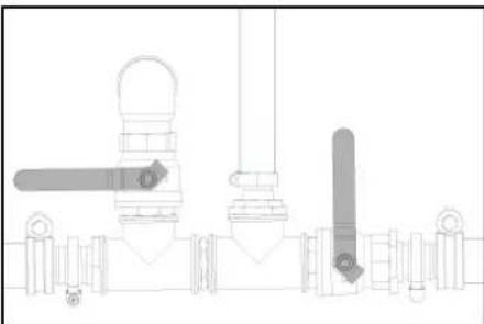
Ball tap of return switchover
- Position parallel to travel direction: The return water from the high-pressure pump flows into the float tank when the overflow valve is open.
Note
If the trigger gun is closed in this ball tap position, the device may switch off after a few minutes due to too high temperature (see Troubleshooting/ERROR 3).
- Position lateral to travel direction: The return water of the high-pressure pump flows into the water reservoirs when the overflow valve is open.
External water supply
- Place the actuation lever of the return flow valve ball tap parallel to the travel direction (20L).
- Close the supply tap of the water reservoir.
Internal water supply
- Set the actuation lever of the return flow valve ball tap lateral to the travel direction (500L).
- Open the supply tap of the water reservoirs.
Turning on the device
Note
The device can only be operated when the front cover is closed. If the front cover is opened, the device shuts down and the indicator light is on.
Note
Due to the bleeding procedure, the speed of the motor may vary until the final operating pressure has been reached.
- Unlock the emergency-stop switch by pulling.
- Open rear cover
- Establish the water supply.
- Insert the key into the key switch.
- With cold motor only: To preheat the motor, turn the key switch to the left and hold it until the indicator light for preheating goes out.
- Turn key switch to position "1". The standby mode indicator light lights up. The control voltage is switch on and the display shows the operating state.
- Turn the key switch to the right until the motor is running.
- Set the power switch to operation with cold/hot water.
- Unlock the high-pressure gun by pushing the safety latch backwards.
- Open the high-pressure gun.
Cold water operation
- Set the power switch to "0/OFF" (burner off).
Operation with hot water
△DANGER
Hot water
Risk of scalding
Avoid contact with hot water.
- Set the power switch to the desired work temperature (max. 100^ ). The burner is switches on.
Speed control
HDS 9/50, HDS 13/35 only (optional with HDS 13/20, HDS 17/20):
Note
If the motor speed is increased, the operating pressure also rises. This can be read from the pressure gauge.
- Increasing the speed:
2. Push up the lever of the speed control.
- Reducing the speed:
3. Push down the lever of the speed control.
Setting the working pressure and flow rate
HDS 13/20, HDS 17/20 only
- Adjust the working pressure and flow rate by turning the pressure/quantity control at the high-pressure gun (+/-) .
△DANGER
Risk of injury!
Take care to ensure that the spray lance screw connection does not release when adjusting the pressure/quantity control.
Operation with detergent
HDS 13/20, HDS 17/20 only:
ATTENTION
Damage from unsuitable detergents
Unsuitable detergents may damage the device and the object to be cleaned.
Only use the detergent intended for the object.
- Use detergents sparingly to conserve the environment.
- Observe the recommended dosage and instructions provided with the detergents.
Only detergents that have been approved by the device manufacturer may be used.
- Kärcher detergents ensure fault-free operation. Ask us for a consultation, request our catalogue or our detergent information sheets.
1. Place the detergent suction hose in a container filled with detergent and tighten the screw cap.
2. Set the detergent dosing valve to the desired concentration.
Note
To prevent detergent from flowing back into the float tank or water reservoirs when operating with detergent and a closed trigger gun, the detergent dosing valve must be closed.
Removal of weeds
HDS 13/20, HDS 17/20 only (option):
Note
The speed control attachment kit (option, ex works: 2.013-086.7, retrofit kit: 2.013-014.0) is absolutely essential for operating the weed removal system! Operation in accordance with the operating instructions for weed removal WR 10, part no. 5.968-256.0 or WR 20/WR 50/WR 100, part no. 5.967-455.0!
The following information must also be observed:
1. Install WR 10, 20, 50 or 100 onto the spray lance and insert the appropriate nozzle (see corresponding operating instructions).
2. Turn key switch to position "I". The standby mode indicator light lights up. The control voltage is switch on and the display shows the operating state.
3. Push the lever of the speed control down as far possible.
Weed Removal V2.0
- Set the power switch to the "Weed removal V2.0" operating mode.
- Turn the key switch to the right until the motor is running.
- Unlock the high-pressure gun by pushing the safety latch backwards.
- Open the high-pressure gun.
TEMP LOW appears on display: It takes about 2 -4 minutes before the work temperature has been reached.
TEMP OKAY appears on display:
- Perform weed removal
Weed Removal V3.0 & V5.0
- Set the power switch to the "Weed removal V3.0 & V5.0" operating mode.
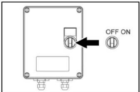
2. Switch on the WR box, set the switch to "ON".
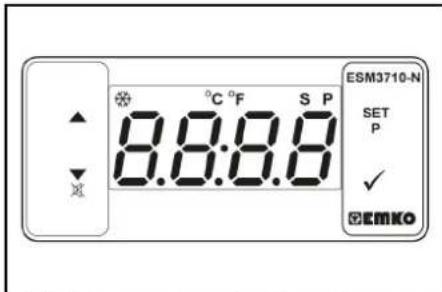
3. Adjust the temperature using SET and the v buttons. Confirm with (setting range, 85-105 °C).
4. Turn the key switch to the right until the motor is running.
5. Unlock the high-pressure gun by pushing the safely latch backwards.
6. Open the high-pressure gun.
Note
It takes about 2 - 4 minutes before the work temperature has been reached.
7. Perform weed removal.
Steam mode (steam cleaning and disinfection)
HDS 13/20, HDS 17/20 only (option):
Note
The speed control attachment kit (option, ex works: 2.013-086.7, retrofit kit: 2.013-014.0) is absolutely essential for operation in steam mode!
△DANGER
Risk of scalding!
Increased working pressure due to high work temperature.
Keep in mind that at work temperatures above 105^ the working pressure must not exceed 3.2MPa (32 bar).
Note
Operation with 2 spray lances is not possible for steam cleaning.
1. Steam cleaning: Fit the appropriate steam nozzle to the spray lance (see technical data for part no.).
2. Disinfection: Mount WR 10, 20, 50, or 100 on the spray lance and insert the appropriate steam nozzle (see Technical Data for part number).
3. Set the power switch to the "steam mode" operating mode.
4. Switch on the WR box, set the switch to "ON".
5. Adjust the temperature using SET and the v buttons. Confirm with (recommended setting range, 120-155 °C).
6. Turn the key switch to the right until the motor is running.
7. Open the bonnet and turn the handwheel on the overflow valve anti-clockwise according to the pressure gauge to 30 bar.
8. Unlock the high-pressure gun by pushing the safety latch backwards.
9. Open the high-pressure gun.
Note
It takes about 2-4 minutes before the work temperature has been reached.
10. Carry out steam cleaning or disinfection. Safety functions
1 WR-Box indicator light lights up red System pressure too high, burner switches off, see Help with faults.
2. ERROR 5 appears on the display on the control panel: System pressure too low, the burner does not start, see Help with faults/ERROR 5.
Interrupting operation
- Close the high-pressure gun.
- Lock the high-pressure gun by pushing the safety latch of the high-pressure gun to the front.
Note
When the high-pressure gun is closed, the motor continues to run at idling speed. This way the water circulates between the float container and the high-pressure pump and heats up. If the maximum admissible temperature (55^) is reached, the motor is switched off by the temperature sensor at the water inlet. After it has cooled down to below 50^ , the device can be put in operation again.
After operation with detergent
HDS 13/20, HDS 17/20 only:
- Set the detergent dosing valve to "0"
- Flush the device clean for at least 1 minute with the high-pressure gun open.
Switching off the device
△DANGER
Risk of injury from hot water or steam
Risk of scalding
After operation with hot water or steam, the device must be operated with the gun opened with cold water for at least two minutes to cool it down.
ATTENTION
Risk of damage!
Risk of damage
Never switch off the motor under full load with the trigger gun open.
- Set the power switch to "0/OFF" (burner off).
- Close the trigger gun.
Motor regulates to idle speed.
- Turn key switch to position "0".
The Standby mode indicator light goes out. The con
trol voltage is switched off and the display goes out.
4. With external water supply: Close the water inlet
5. Actuate the high-pressure gun until the device is depressurised.
6. Secure the high-pressure gun with the safety latch against unintentional opening.
7. With external water supply: Disconnect the water hose from the water inlet and coil up the water hose onto the hose reel.
8. Coil the high-pressure hose onto the hose reel.
Antifreeze
To protect from freeze damage, the device must be flushed with antifreeze.
Note
Use normal glycol-based anti-freezing agents for automobiles.
Note
Observe the handling instructions of the anti-freeze manufacturer.
This also provides a certain degree of corrosion protection.
Motor antifreeze
- Check the coolant circuit of the motor for sufficient antifreeze, refill antifreeze as needed.
- See Maintenance Procedures "Check and refill the coolant".
Battery frost protection battery
- If the device is not used for an extended period and if there is frost, remove the battery and store it in a location protected from frost.
Antifreeze rinse in the circuit (high pressure pump)
- With external water supply: Disconnect the water hose from the water inlet.
- Set the power switch to "0/OFF" (burner off).
- Depressurise the device
- Set the power switch to the operating mode "protection".
- HDS 13/20, HDS 17/20 only: Set dosing valve for detergent to maximum. Pull the delergent suction hose out of the detergent container and place it in such a way that it can be sucked empty.

6. Open the supply tap of the water reservoirs and the drain tap in order to completely drain the device.
The filling level indicator of the water reservoirs dips completely.
- Close the supply tap of the water reservoirs and the drain tap.
- Disconnect the high-pressure gun from the high-pressure hose.
9. Connect the high-pressure hose to the frost protection inlet.
- Connect the water hose to the return flow of the frost protection.
- Prepare the antifreeze in the antifreeze container. Select the mixing ratio of the water/antifreeze as per the instructions of the antifreeze manufacturer.
- Check the antifreeze concentration with a commercially available antifreeze tester and adapt if necessary.
- Open the filling hole of the float container. In order to do so, loosen the wing screw and push the cover to the left.
- Fill 20 litres of antifreeze into the float container and close the filling hole.
- Align the actuation lever of the ball tap for antifreeze vertically.
- Place the actuation lever of the return flow valve ball tap parallel to the travel direction (20L).
- With cold motor only: To preheat the motor, turn the key switch to the left and hold it until the indicator light for preheating goes out.
- Turn key switch to position "I". The standby mode indicator light lights up. The control voltage is switch on and the display shows the operating status "Antifreeze".
- Turn the key switch to the right until the motor is running.
The antifreeze liquid is pumped through the device in a circuit.
- Lead the residual water via the frost protection hose into the anti-freeze container.
- As soon as antifreeze exits the antifreeze hose, put the operating lever of the frost protection ball tap in the horizontal position and wait for 5 seconds.
- Switch off the engine.
- Set the power switch to "0/OFF" (burner off).
Pumping antifreeze out of the high pressure system
Note
Prior to operation, the antifreeze must be pumped from the high-pressure system back into the antifreeze container
-
Align the actuation lever of the ball tap for antifreeze vertically.
-
Connect the high-pressure hose to the frost protection inlet.
- Connect the water hose to the return flow of the frost protection.
- Open the filling hole of the float container. In order to do so, loosen the wing screw and push the cover to the left.
- Fill 20 litres of fresh water into the float container and close the filling hole.
- Set the power switch to the operating mode "frost protection".
- With cold motor only: To preheat the motor, turn the key switch to the left and hold it until the indicator light for preheating goes out.
- Turn key switch to position "I". The standby mode indicator light lights up. The control voltage is switch on and the display shows the operating status "Antifreeze".
- Turn the key switch to the right until the motor is running. The antifreeze fluid is forwarded from the float container into the antifreeze container with fresh water.
- Rinse for approx. 2 minutes until the antifreeze container is filled.
- Switch off the engine.
- Set the power switch to "0/OFF" (burner off).
Transport
CAUTION
Risk of injury and damage!
Improper transportation Mind the weight of the device during transport.
ATTENTION
Risk of damage!
Improper transportation
Protect the trigger from damage during transport.
Trailer operation
Note: The driver driving the towing vehicle on public roads must ensure that he/she has the appropriate license for this (driving license class).
△DANGER
Unpredictable driving behaviour
With a partially filled water reservoir, the device can rock up or tip over under extreme steering movements or braking situations.
Drain or fill the water reservoir before driving.
- With a permissible total weight of 1600kg fill or empty the water reservoir completely. With a permissible total weight of 1100kg empty the water reservoir completely.
- On devices without a hose reel, unscrew the high-pressure hose from the high-pressure outlet and stow it in the device.
- Pivot the front bar (option) forwards and lock in place.
- Pull the rear tarpaulin (option) down an lock in place.
- Use the support wheel to adjust the tow bar to the height of the towing hitch on the towing vehicle.
- Attach the tear-off rope to the towing vehicle.
- Remove the chocks from the wheels and insert them into the holders.
- Release the parking brake.
- Check that the trailer lighting system (brake lights, indicator lights, tail lights, license plate light) is functioning correctly.
- Check the running surfaces of the tyres for embedded objects.
- Check the condition of the tyres.
- Check the tyre pressure, see "Maintenance work". Note: Note the locally applicable speed limits for vehicles with trailers and adhere to these.
Crane transport
△DANGER
Improper crane transport
Risk of injury from a falling device or falling objects Observe the local regulations for accident prevention and the safety instructions.
The device may only be transported with a crane by persons instructed in the operation of the crane.
Check the lifting gear for damage before each crane transport.
Check the handle for damage before each crane transport.
Lift the device only by the handle.
Do not use an slinging chains.
Secure the lifting gear against unintentional unhooking of the load.
Remove the spray lance with high-pressure gun, nozzles, surface cleaner and other loose objects before transporting by crane.
Do not transport any objects on the device during the lifting operation.
Do not stand under the suspended load.
Ensure that no persons are in the hazard zones of the crane.
Do not leave the device handling unattended on the crane.
Storage
CAUTION
Risk of injury or damage due to non-observation of the weight!
When transporting and storing the device, there is a risk of injury and damage due to its weight.
Take into account the weight of the device for transportation and storage, see chapter Technical data.
ATTENTION
Risk of damage due to frost!
Water that is not completely drained can damage the device and accessories during freezing.
Empty the water completely from the device and accessories.
Protect the device and accessories from frost.
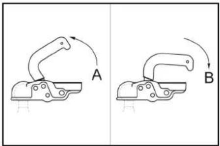
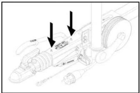
(1)Towing hitch open
(2)Towing hitch closed
7. Pull the coupling lever up (open).
8. Fit the tow bar onto the towing hitch ball.
9. Press the coupling lever down (close) until it lies parallel to the tow bar.
10. Plug in the socket plug connection for the vehicle lighting.
11. Rotate the support wheel up by means of the crank.
12. Ensure that the support wheel points toward the trailer when fully retracted.
Care and service
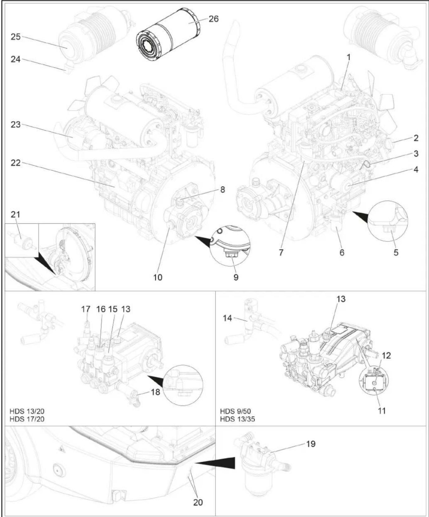
①Motor oil filling hole (top)
2Motor oil filling hole (lateral)
③ Oil dipstick (motor)
(4) Oil filter (motor)
⑤ oil drain screw of motor
(6)Water separator
⑦ Fuel filter
8Filling hole for transmission oil incl. venting
(9)Pill drain screw of intermediate transmission
(10) Oil sight glass for intermediate gearbox
Pump oil drain screw
12 Oil sight glass pump
(13) Oil dipstick (pump)
(14)Safety block of burner
(15)Frost protection rinsing valve
16Pressure switch
17Overflow valve
(18)Detergent inlet
(19)Pump prefilter
(20)Inspection slot
2 Fuel filter
22 Starter
(2)Alternator
(24)Dirt outlet at the air filter
25Air filter
26Air filter insert

Flow chart
(1) Antifreeze container
(2) Liquid softener container
(3)Water inlet
(4) Low-pressure hose reel
(5)Water inlet filter
6Frost protection ball tap
(7)Float container
(8)Water shortage safeguard
Supply tap of water reservoirs
Water reservoir
1Ball tap of return switchover
(12)Pump prefilter
③ High-pressure pump
(4)Overflow valve
(5)Pressure switch
(16)Check valve
(17)Safety valve
(18)Flow switch
(9)Booster heater
20Temperature sensor of the burner
21)High pressure hose reel
(22)High-pressure outlet
23Backflow frost protection
(24)Drain tap
(25) Temperature sensor water inlet
26Heat exchanger
27)Intermediate transmission
28Diesel engine
(29)Pressure gauge
30 Temperature sensor for cooling water
Detergent solenoid valve
32Detergent dosing valve
(33)Detergent container

Customer Service display
| Symbol Type of Customer Service | |
| Burner service | |
| Motor service | |
| Pump service | |
| High-pressure gun service | |
Maintenance intervals
| Time & date Activity By whom | ||
| Before each journey Check lighting. Operator | ||
| Check the tyre pressure and condition of the tyres. Operator | ||
| Daily Check the condition of the oil in the high-pressure pump sight glass. Do not start up the device if the oil is milky. Notify Customer Service.ATTENTIONRisk of damage!In case of lacticous oil, inform Kärcher customer service immediately | Operator | |
| Check the high-pressure hose for damage. Do not continue using damage high-pressure hoses. | Operator | |
| Check the water inlet filter, clean if necessary Operator | ||
| Check the pump prefilter, clean if necessary. Operator | ||
| Check oil level on the motor, refill oil if necessary. | Operator | |
| Check oil level at the intermediate gearbox, refill oil if necessary. | Operator | |
| Check the fuel filter on the motor, inform customer service if necessary. | Operator | |
| Check the water separator on the motor, inform customer service if necessary. | Operator | |
| Check coolant level in the equalisation container, refill coolant if needed. | Operator | |
| Check fuel filter, contact customer service if necessary. | Operator | |
| Check the filter on the detergent suction hose, clean if necessary. | Operator | |
| Check line system for leaks. | Operator | |
| Once after the first 50 operating hours | Check the V-belt tension at the fan, retension if necessary. | Operator |
| Replace oil in the motor. | Customer Service department | |
| Change the oil in the high pressure pump. | Customer Service department | |
| Every 50 operating hours or 3 months | Check the battery. | Customer Service department |
| Time & date | Activity | By whom |
| Every 200 operating hours | Check the air filter or air filter inlay, clean if necessary. | Operator |
| Check the V-belt tension at the fan, retension if necessary. Operator | ||
| Check the intermediate gearbox for leaks. Customer Service | department | |
| Clean the sieve on the filling nozzle of the fuel tank. Customer Service | department | |
| Replace oil in the motor. Customer Service | department | |
| Replace oil filter inlay on motor. Customer Service | department | |
| Perform maintenance tasks in accordance with the maintenance plan. Customer Service | department | |
| Every 400 operating hours or annually | Replace the air filter insert. | Operator |
| Check fuel filter, replace if necessary. | Customer Service department | |
| Perform maintenance tasks in accordance with the maintenance plan. Customer Service | department | |
| Every 600 operating hours or annually | Change the oil in the high pressure pump. | Customer Service department |
| Every 800 operating hours. | Check the blower motor for proper function, replace sliding contacts (carbon brushes) if necessary. | Operator |
| Every 1000 operating hours or annually. | Replace coolant. | Customer Service department |
| Every 1000 operating hours. | Replace oil in the intermediate gearbox. | Customer Service department |
| Replace V-belt on the ventilator. | Customer Service department | |
| Check the valve clearance at the cylinder head of the motor, adjust if necessary. | authorized Yan-mar dealer | |
| Every 1600 operating hours. | Check injectors on the motor, clean if necessary. | authorized Yan-mar dealer |
| Check the crankshaft casing ventilation on the motor, clean if necessary. | authorized Yan-mar dealer | |
| Every 2000 operating hours or every 2 years | Replace fuel hoses on the motor. | authorized Yan-mar dealer |
| Replace cooling system hoses on the motor. | authorized Yan-mar dealer | |
| Every 2000 operating hours | Check the valves and valve seats on the cylinder head of the motor, lap if necessary. | authorized Yan-mar dealer |
| Only applies to devices with vapour mode attachment kit: | ||
| Recurring every 5 years at the latest | Perform the pressure test according to the manufacturer's specifications. | Customer Service department |
Maintenance work
△DANGER
Turn the key-operated switch to off and remove the key before performing any work on the device.
DANGER
Risk of injury from electric shock
Do not place metallic objects on the alternator or the starter.
DANGER
Risk of explosion!
Risk of injury and damage
Do not place any tools or objects on the battery, i.e. on the end poles and cell connectors.
Naked flames and smoking must be strictly avoided. Ensure the room is well ventilated when charging batteries.
Only use batteries and chargers approved by Karcher (original spare parts).
- Allow the device to cool down.
Cleaning the water inlet filter
-
Disassemble the water inlet filter and take out the filter inlay.
-
Clean the filter with clean water or compressed air.
-
Assemble in the reverse order
Cleaning the pump prefilter
- Depressurise the device.
- Disassemble the pump prefilter and take out the filter inlay.
- Clean the filter with clean water or compressed air.
- Assemble in the reverse order
In the filter on the detergent suction hoses
- Unscrew the screw cap of the detergent suction hose.
- Take out detergent suck hose
- Clean filter in water and reinstall.
Check the oil level on the motor and top up
Note
The filling quantity between the MIN and MAX markings on the oil dipstick is 1.6 litres.
1. Remove the oil dipstick, wipe it and reinsert it.
2. Remove the oil dipstick one more time and check the oil level. The oil level is correct if it is within the markings of the oil dipstick.
3. If the oil level is below the mark, open the filling hole and add fresh motor oil.
4. Wait five minutes, until the oil has collected in the oil pan.
5. Check the oil level as described above.
6. Repeat this procedure as often as necessary until the oil level is between the markings on the oil dipstick.
7. After the check, insert the oil dipstick and close the lid of the filling hole.
Note
The air bubbles must be able to escape.
For oil type refer to technical specifications
Check the oil level on the intermediate gearbox and refill transmission oil
- Check the oil level at the oil-level gauge of the intermediate gearbox.
The oil level is correct if it is in the middle of the oil-level gauge. - If the oil level is below the middle of the oil-level gauge, open the lid of the filling hole and fill in fresh transmission oil.
- Close filling hole.
Note
The air bubbles must be able to escape.
For oil type refer to technical specifications
Check the oil level on the oil dipstick of the high-pressure pump, refill oil if necessary
- Remove the oil dipstick, wipe it and insert it again.
- Remove the oil dipstick again and check the oil level.
The oil level is correct if it is within the markings on the oil dipstick.
-
If the oil level is below the mark on the oil dipstick, fill up with fresh oil.
-
Twist in the oil dipstick.
Note
Air bubbles must be able to escape.
For oil type refer to technical specifications
Check the coolant and refill
CAUTION
Harmful substances can be produced.
Observe the brand of antifreeze used.
The mixture can cause a chemical reaction. Do not mix different types of antifreeze.
WARNING
Risk of motor overheating
A lack of coolant can cause the motor to overheat. Switch off the motor immediately and allow it to cool down.
△WARNING
Risk of motor overheating
A lack of coolant can cause the motor to overheat. If the motor overheats to the point where steam escapes, turn off the motor and maintain a safe distance until the pressure has decreased.
ATTENTION
Danger of scalding from motor coolant
The expansion tank is pressurised
Never open the lid on the expansion tank of the motor coolant at operating temperature.
- Open the lid on the expansion tank of the motor coolant, fill in fresh clean water and the required antifreeze.
Check/clean the air filter
Note
For a coarse cleaning of the air filter, hold the catch pan under the dirt outlet and operate the dirt outlet.
Note
Heavily soiled or defective filter inlays must always be replaced.
- Loosen the spring tension bracket, remove the cover and eliminate the dust deposits.
-
Take out the filter inlay.
-
Blow out the filter inlay with compressed air (max. 2 bar) from the inside.
- Clean the inside of the air filter housing with a cloth.
- Insert the filter inlay into the air filter casing.
- Attach the cover and fasten it by means of the spring tension bracket.
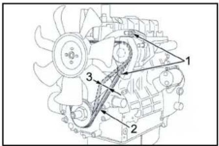
Check the ventilator V-belt
①Fastening screws of generator
(2)V-belt
③ Belt tension approx. 7 - 9mm
Note
If the V-belt is not sufficiently tensioned, this can cause overheating of the motor or insufficient battery charge.
- Shut off the motor and remove the key from the key switch.
- Press the belt with your thumb to check the V-belt tension.
Note
You should be able to push the V-belt in by approx. 7-9 mm.
Note
The defective V-belts must be replaced immediately.
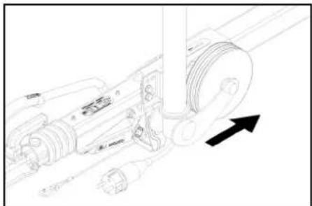
- Use a commonly available grease gun to inject the appropriate grease into both grease nipples.
Lubricating the inertia brake
①Grease nipple
Checking the tyre pressure
- Place the device on a level surface.
- Connect the tyre pressure gauge device to the tyre valve.
- Check the type pressure (see "Technical data") and correct if necessary.
Changing a wheel
DANGER
Risk of fatal injury from moving traffic
Park the device on a level surface and wear high-visibility clothing when carrying out repair work on public roads.
- Park the device on a level surface.
- Check that the ground is stable. Additionally secure the device against rolling away with a wheel chock
- Lock parking brake.
- Check the tyres.
- Check the tyre running surfaces for embedded objects.
- Remove objects found.
- Use suitable, commercially available materials to carry out tyre repairs.
Note
Observe the manufacturer's recommendations. The journey may be resumed providing that the directions supplied by the product manufacturer have been observed. The tyre/wheel change should nonetheless be carried out as soon as possible.

- Place the jack at the relevant position point.
- Loosen the wheel screws.
- Lift the device with a jack.
- Unscrew the wheel bolts.
- Remove the wheel.
- Mount spare wheel.
- Apply the wheel bolts.
- Lower the device with the jack.
- Tighten the wheel screws crosswise.
Tightening torque 110-120 Nm
Note
No jack included in the scope of delivery.
Note
Use a suitable, commonly available jack.
Trailer
- Have the brake system and the Chassis and Suspension checked regularly by an authorised dealer workshop.
Troubleshooting guide
△DANGER
Inadvertently starting up device
Risk of injury, electric shock
Turn the key-operated switch to "0" and remove the key before performing any work on the device.
△DANGER
Inadvertently starting up device, touching live components
Risk of injury, electric shock
Switch off the device before performing any work on the device.
Remove the mains plug.
△DANGER
Risk of explosion and short-circuit. Do not place any tools or similar on the battery.
1 Allow the device to cool down.
Display malfunction
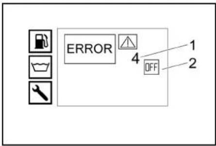
1 Fault number
②Motor off (OFF)
Customer Service department
If the malfunction cannot be corrected, the device must be checked by the Customer Service department.
Malfunctions with information shown on the display
| Fault | Cause | Rectification | Person responsible |
| ERROR 1 Charging current | V-belt tension on the fan too low. | 1.Retension the V-belt on the fan. | Operator |
| Alternator defective. 1. Check alternator, replace if necessary. Customer Service depart-ment | |||
| Charging current monitoring defective. | 1. Check wiring + relay K9. | Customer Service depart-ment | |
| ERROR 3 Temperature of water inlet or cooling water | Water temperature in the float container too high due to circulation mode. | 1. Allow the water to cool down or drain it. Set the actuation lever of the return flow valve ball tap lateral to the travel direction (500L). | Operator |
| Temperature sensor of water inlet has switched off the device | 1. Turn the device off and back on. If the malfunction occurs repeatedly, notify customer service. | Operator | |
| Temperature sensor of water inlet defective. | 1. Replace the temperature sensor. | Customer Service depart-ment | |
| Coolant level too low. | 1. Fill coolant into the expansion tank. | Operator | |
| V-belt tension on the fan too low. 1. Retension the V-belt on the fan. Operator | |||
| Temperature sensor for cooling water on the motor defective. | 1. Replace the temperature sensor. | Customer Service depart-ment | |
| ERROR 4 Water shortage External water supply: Water inlet pressure too low. | Internal water supply: Water reservoirs emp-ty. | 1. Check the water inlet. Operator | |
| Water shortage safeguard in the float contain-er defective. | 1. Fill water reservoirs. Operator | ||
| Water inlet filter dirty. 1. Clean the water inlet | 1. Replace the water shortage safeguard. Customer Se | vice depart-ment | |
| Water hose leaky or kinked. 1. Replace water | filter. Operator | ||
| Float valve in the float container is soiled. | hose. Customer Service depart-ment | ||
| Float valve in the float container jammed or defective. | 1. Clean float valve. | Customer Service depart-ment | |
| ERROR 5 Flow switch / pressure switch | Flow switch defective. 1. Replace flow switch | Customer Service depart-ment | |
| Pressure switch faulty. | 1. Replace the pressure switch. | Customer Service depart-ment | |
| Overflow valve is defective. | 1. Replace overflow valve. | Customer Service depart-ment | |
| Check valve in the overflow valve defective. | 1. Replace the check valve. | Customer Service depart-ment | |
| Pump prefilter dirty. 1. Clean the pump prefilter. | Operator | ||
| Steam mode: System pressure too low | 1. Raise the system pressure in small increments by turning the handwheel on the overflow valve clock-wise. | Operator | |
| ERROR 6 Fuel sensor | Fuel tank empty. | 1. Refuel. | Operator |
| Float of the fuel sensor jammed. | 1. Check the float. | Customer Service depart-ment | |
| Fuel sensor defective. | 1. Replace fuel sensor. | Customer Service depart-ment | |
| ERROR 9* Emission temperature | Exhaust gas thermostat has responded and switched off the burner. | 1. Switch off the device, allow to cool down and restart. If the malfunction occurs repeatedly, notify customer service. | Operator |
| Exhaust gas thermostat defective. | 1. Replace the exhaust gas thermostat. | Customer Service depart-ment | |
| Burner has been wrongly set. | 1. Adjust the burner. | Customer Service depart-ment | |
| Heating coil soiled or calcified. | 1. Decarbonise or descale heating coil. | Customer Service depart-ment | |
| ERROR 10* Burner temperature Cleaning operation with cold water is possible. | Temperature sensor for burner (NTC) has switched off the burner. | 1. Turn the device off and back on. If the malfunction occurs repeatedly, notify customer service. | Operator |
| Temperature sensor of the burner is defec-tive. | 1. Replace the temperature sensor. | Customer Service depart-ment | |
| ERROR 11* Flame sensor (no flame) Cleaning operation with cold water is possible. | Nozzle holder soiled. | 1. Clean the nozzle holder. | Customer Service depart-ment |
| Ignition electrodes have been set up wrongly or are dirty. | 1. Properly adjust or clean the ignition electrodes. | Customer Service depart-ment | |
| Photo cell of the flame monitoring defective. | 1. Replace the photo cell. | Customer Service depart-ment | |
| Fuel pump defective. | 1. Replace fuel pump. | Customer Service depart-ment | |
| Solenoid valve fuel is defective. | 1. Replace the solenoid valve. | Customer Service depart-ment | |
| Fuel filter choked. | 1. Replace fuel filter. | Customer Service depart-ment | |
| Ignition transformer defective. | 1. Replace the ignition transformer. | Customer Service depart-ment | |
| ERROR 12* Flame sensor (flame does not go out) Cleaning operation with cold water is possible. | Photo cell of the flame monitoring defective. | 1. Replace the photo cell. | Customer Service depart-ment |
| Burner sooted, "afterglow". | 1. Have the burner decarbonised. | Customer Service depart-ment | |
| ERROR 14 Switch-off after 45 minutes continuous break | Standby time of 45 minutes exceeded. | 1. Turn the device off and back on. | Operator |
| ERROR 15 Switch-off after 45 minutes continuous operation | Continuous operation exceeds 45 minutes. | 1. Turn the device off and back on. | Operator |
Troubleshooting with nothing shown on the display
| Fault | Cause | Rectification | Person responsible |
| Device stops, display switches off | Blown fuse. | 1. Replace fuse. | Operator |
| No power supply to inverter because of battery undervoltage or overvoltage. | 1. Check battery, charge if necessary. | Operator | |
| Inverter defective. | 1. Replace inverter. | Customer Service depart-ment | |
| No display after switching the device on | Battery depleted. 1. Charge the battery. Operator | ||
| Blown fuse. 1. Replace fuse. Operator | |||
| Front cover open. 1. Close front cover. Operator | |||
| Emergency stop switch depressed. 1. Unlock the emergency-stop switch by pulling. Operator | |||
| No power supply to inverter because of battery undervoltage or overvoltage. 1. Check battery, charge if necessary. Operator | |||
| Inverter defective. 1. Replace inverter. Cus tomer Service depart-ment | |||
| Engine does not start or stops again immediately | Notify Customer Service. | ||
| Working pressure fluctuates Leak in the suction section of the high-pressure pump. | 1. Check line system. Customer Service depart-ment | ||
| Valves worn. 1. Replace valves. Customer Service depart-ment | |||
| Burner emitting sooty smoke | Burner incorrectly adjusted or soiled. 1. Adjust or clean burner. | Customer Service depart-ment | |
| Solenoid valve fuel defective, diesel fuel is dripping. 1. Check the solenoid valve; replace solenoid or sole-noid valve if necessary. | Customer Service depart-ment | ||
| White smoke from burner | No ignition spark (can be detected through the sight glass in the burner lid). 1. Notify Customer Service. | Operator | |
| Condensation in the nozzle holder. 1. Check, clean the nozzle holder. | Customer Service depart-ment | ||
| Fuel pressure too low. 1. Check the fuel pump. | Customer Service depart-ment | ||
| Indicator light front cover/emergency stop is on | The front cover was opened during the operation. 1. Close front cover. | Operator | |
| Safety button of front cover is defective. 1. Check safety button. | Customer Service depart-ment | ||
| Emergency stop switch depressed. 1. Unlock the emergency-stop switch by pulling. Operator) | |||
| Water leaks from the bottom of the device. | High-pressure pump is leaky. Note: 3 drops/minute are permitted. With stronger leak, have device checked by customer service. | Customer Service depart-ment | |
| Device not building up pressure | Nozzle is blocked/ washed out. 1. Clean/replace the nozzles. | Customer Service depart-ment | |
| Motor operating speed too low. 1. Check the operating speed of the motor. | Customer Service depart-ment | ||
| HDS 9/50, HDS 13/35 only (optional with HDS 13/20, HDS 17/20): Speed control defective. | Customer Service depart-ment | ||
| Safety valve is leaky. 1. Check the setting; install new washers, if required. | Customer Service depart-ment | ||
| Supply lines to the pump are leaky or clogged. 1. Check all supply lines to the pump. | Customer Service depart-ment | ||
| High-pressure pump knocking | Supply lines to the pump are leaky. 1. Check all supply lines to the pump. | Customer Service depart-ment | |
| HDS 13/20, HDS 17/20 only: Insufficient or no detergent delivery | Detergent dosing valve is closed or leaking/clogged 1. Open or check/clean detergent dosing valve. | Operator | |
| Detergent suction hose with filter leaking or blocked 1. Check/clean detergent suction hose with filter. | Operator | ||
| Detergent solenoid valve leaky or clogged. 1. Check, clean detergent solenoid valve. | Customer Service depart-ment | ||
| Electronics or detergent solenoid valve is defective. 1. Replace electronics or detergent solenoid valve. | Customer Service depart-ment | ||
| Overflow valve keeps switching on/off when the trigger gun is opened | Nozzle is clogged. 1. Clean the nozzles. | Operator | |
| Device is scaled. 1. Descale the device. | Customer Service depart-ment | ||
| Overflow valve is defective. 1. Replace overflow valve. | Customer Service depart-ment | ||
| The switching point of the overflow valve has become misaligned 1. Adjust the overflow valve. | Customer Service depart-ment | ||
| WR-Box indicator light lights up red | Steam mode: System pressure too high | Lower the system pressure in small increments by turn- ing the handwheel on the overflow valve anticlockwise. | Operator |
Warranty
The warranty conditions issued by our relevant sales company apply in all countries. We shall remedy possible malfunctions on your appliance within the warranty period free of cost, provided that a material or manufacturing flaw is the cause. In a warranty case, please contact your dealer (with the purchase receipt) or the next authorised customer service site. (See overleaf for the address) Further warranty information (if available) can be found in the service area of your local Kärcher website under "Downloads".
Accessories and spare parts
Note
If the device is connected to a chimney or if the device cannot be seen, we recommend installing a flame monitor (option).
Only use original accessories and original spare parts.
They ensure that the appliance will run safely and fault
free.
Information on accessories and spare parts can be
found at www.kaercher.com.
Declaration of Conformity
EU Declaration of Conformity
We hereby declare that the machine described below complies with the relevant basic safety and health requirements in the EU Directives, both in its basic design and construction as well as in the version placed in circulation by us. This declaration is invalidated by any changes made to the machine that are not approved by us.
Product: High-pressure cleaner
Type: 1.524-xxx
Type: 1.999-380.0
Currently applicable EU Directives
2006/42/EC(+2009/127/EC)
2000/14/EC
2014/30/EU
2014/68/EU (optional)
Harmonised standards used
EN 60335-
EN 60335-2-79
EN 1829-1
EN 1829-2
EN ISO 12100
EN 13309:2010
EN 55012: 2007 + A1: 2009
EN 62233: 2008
Applied conformity evaluation method
2000/14/EG:Annex V
Sound power level dB(A)
HD 9/23 Getr1 + HD 9/23 DeTr1
Measured: 105
Guaranteed: 107
HDS 13/20 DeTr1
Measured: 97
Guaranteed: 100
HDS 13/35 DeTr1 + HDS 9/50 DeTr1
Measured: 100
Guaranteed: 102
HDS 17/20 DeTr1
Measured: 100
Guaranteed: 102
OPTIONAL
Product: ABS steam HDS 1000
Type: 2.013-093.0
Category of the assembly
Conformity process
Module H1
Heating coll
Module H1 conformity evaluation
Control block
Module H1 conformity evaluation
Various pipelines
Conformity evaluation Art. 4 Para. 3
Applied specifications:
AD 2000 based on
TRD 801 based on
Name of stated position:
2014/68/EU
The signatories act on behalf of and with the authority of the company management.

H.Jenner
Chairman of the Board of Management
S. Reiser
Manager Regulatory Affairs & Certification
Documentation supervisor:
S. Reiser
Alfred Karcher SE & Co. KG
Alfred-Karcher-Str.28-40
71364 Winnenden (Germany)
Ph.: +49 7195 14-0
Fax: +49 7195 14-2212
Winnenden, 2023/01/01
Declaration of ConformityUK
We hereby declare that the product described below complies with the relevant provisions of the following
UK Regulations, both in its basic design and construction as well as in the version put into circulation by us.
This declaration shall cease to be valid if the product is modified without our prior approval.
Product: High-pressure cleaner
Type: 1.524-xxx
Type: 1.999-380.0
Currently applicable UK Regulations
S.I. 2008/1597 (as amended)
S.I. 2001/1701 (as amended)
S.I. 2016/1091 (as amended)
S.I. 2016/1105 (as amended)
Designated standards used
EN 60335-1
EN 60335-2-79
EN 1829-1
EN 1829-2
EN ISO 12100
EN 13309:2010
EN 55012: 2007 + A1: 2009
EN 62233:2008
Applied conformity assessment procedure
S.I. 2001/1701 (as amended): Schedule 8
Sound power level dB(A)
HD 9/23 GeTr1 + HD 9/23 DeTr1
Measured: 105
Guaranteed
HDS 13/20 DeTr1
Measured: 97
Guaranteed: 100
HDS 13/35 DeTr1 + HDS 9/50 DeTr1
Measured: 100
Guaranteed: 102
HDS 17/20 DeTr1
Measured: 100
Guaranteed: 102
OPTIONAL
Product: ABS steam HDS 1000
Type:2.013-093.0
Category of the assembly
Conformity process
Module H1
Heating coil
Module H1 conformity evaluation
Control block
Module H1 conformity evaluation
Various pipelines
Conformity evaluation Art. 4 Para. 3
Applied specifications:
AD 2000 based on
TRD 801 based on
Name of stated position:
S.I. 2016/1105 (as amended)
TÜV Rheinland UK
Friars Gate (Third Floor)
1011 Stratford Road
Shirley
Solihull 200-4D1
United Kingdom
The signatories act on behalf of and with the authority of
the company management.

H.Jenner
Chairman of the Board of Management
S. Reiser
Manager Regulatory Affairs & Certification
Documentation supervisor:
S. Reiser
Alfred Karcher SE & Co. KG
Alfred-Karcher-Str. 28 - 40
71364 Winnenden (Germany)
Ph.: +49 7195 14-0
Fax: +49 7195 14-2212
Winnenden, 2023/01/01
Technical data
HDS 9/50 DE Tr1 HDS 13/35 DE Tr1 HDS 13/20 DE Tr1 HDS 17/20 DE Tr1
Water connection
| Input temperature (max.) °C 30 30 30 | |||||
| Input amount (min.) l/h (l/min) 1000 (16,7) 1500 (25) 1500 (25) 1800 (30) | |||||
| Feed pressure (max.) MPa (bar) 0,05-1 (0,5-10) 0,1-1 (1-10) 0,1-1 (1-10) 0,15-1 (1,5-10) | |||||
| Device performance data | |||||
| Water flow rate l/h (l/min) 500-900 (8,3-15) 650-1300 (10,8- | 21,7) | 900-1300 (15-21,7) | 900-1700 (15-28,3) | ||
| Water operating pressure with standard nozzle | MPa (bar) | 15-50 (150-500) | 10-35 (100-350) | 6-20 (60-200) | 6-20 (60-200) |
| Excess operating pressure safety valve (maximum) | MPa (bar) | 64 (640) | 44 (440) | 24 (240) | 24 (240) |
| Steam operation flow rate | l/h (l/min) | -- | -- | 460 (7,7) | 460 (7,7) |
| Steam flow rate for disinfection | l/h (l/min) | -- | -- | WR 10, WR 20: 360 (6) | WR 10, WR 20: 360 (6) |
| WR 50, WR 100: 460 (7,7) | WR 50, WR 100: 460 (7,7) | ||||
| Steam operation operating pressure with steam nozzle (max.) | MPa (bar) | -- | -- | 3,2 (32) | 3,2 (32) |
| Part no. Steam nozzle (nozzle size) for steam cleaning | -- | -- | 2.113-026.0 (060) | 2.113-026.0 (060) | |
| Part no. Steam nozzle (nozzle size) for disinfection | -- | -- | WR 10, WR 20: 2.113-022.0 (045) | WR 10, WR 20: 2.113-022.0 (045) | |
| WR 50, WR 100: 2.113-026.0 (060) | WR 50, WR 100: 2.113-026.0 (060) | ||||
| Drive motor performance | kW | 15,5 | 15 | 9 | 11 |
| Engine speed | 1/min | 3100 | 3300 | 2700 | 3300 |
| Battery | V/Alh | 12/41 | 12/41 | 12/41 | 12/41 |
| Hot water operating temperature (maximum) | °C | 30-98 | 30-98 | 30-98 | 30-98 |
| Steam operation working temperature | °C | -- | -- | 155 | 155 |
| Detergent flow rate | l/h (l/min) | -- | -- | 0-50 (0-0,8) | 0-70 (0-1,2) |
| Burner output | kW | 65 97 105 | 105 | ||
| Fuel consumption (max.) | l/h | 11,7 | 15 | 13,7 | 14,3 |
| Fuel consumption in cold-water-mode | l/h | 5,2 | 5,1 | 3,1 | 3,7 |
| High-pressure gun recoil force | N | 79 96 72 94 | |||
| Nozzle size of standard nozzle | 030 | 051 | 075 | 090 | |
| Operating materials | |||||
| Fuel | Diesel | Diesel | Diesel | Diesel | |
| Oil quantity of Intermediate transmission | I | 0,35 | 0,35 | 0,35 | 0,35 |
| Oil grade of intermediate transmission | SAE90 | SAE90 | SAE90 | SAE90 | |
| Pump oil volume | I | 1,2 | 1,2 | 1,3 | 1,3 |
| Pump oil type | 15W40 | 15W40 | 15W40 | 15W40 | |
| Engine oil volume | I | 3,5 | 3,5 | 3,5 | 3,5 |
| Motor oil type | 15W40 | 15W40 | 15W40 | 15W40 | |
| Dimensions and weights | |||||
| Length x width x height | mm | 3646 x 1747 x 1735 | 3646 x 1747 x 1735 | 3646 x 1747 x 1735 | 3646 x 1747 x 1735 |
| Weight without operating fuels | kg | 860-1020 | 860-1020 | 860-1020 | 860-1020 |
| Total weight including consumables and standard accessories | kg | 1440-1600 | 1440-1600 | 1440-1600 | 1440-1600 |
| Permitted axle load | kg | 1600 | 1600 | 1600 | 1600 |
| Permissible support load (max.) | kg | 1100/1600 | 100 | 100 | 100 |
| Approved total weight (max.) | kg | 100 | 1100/1600 | 1100/1600 | 1100/1600 |
| Fuel tank | I | 100 | 100 | 100 | 100 |
| Water reservoir | I | 500 | 500 | 500 | 500 |
| Cooling system | I | 5 | 5 | 5 | 5 |
| Liquid softener | I | 1 | 1 | 1 | 1 |
| Antifreeze | I | 20 20 20 20 | |||
| Detergent tank | I | -- | -- | -- | -- |
| Tires | Type approval ac-cording to ECE R 30, ECE R 54, ECE R 108 or ECE R 109 as well as ECE R 117 | Type approval ac-cording to ECE R 30, ECE R 54, ECE R 108 or ECE R 109 as well as ECE R 117 | Type approval ac-cording to ECE R 30, ECE R 54, ECE R 108 or ECE R 109 as well as ECE R 117 | Type approval ac-cording to EQR 30, EQR 54, EQR 108 or EQR 109 as well as EQR 117 | |
| Tyre size | 185 R 14 C | 185 R 14 C | 185 R 14 C | 185 R 14 C | |
| Load capacity index | 104 | 104 | 104 | 104 | |
| Speed rating | N | N | N | N | |
| Wheel size/rim shape | 5,5 J x 14 5,5 J x 14 5,5 J x 14 5,5 J x 14 | ||||
| Offset | 30 30 30 30 | ||||
| Tyre pressure | MPa (bar) 0,45 (4,5) 0,45 (4,5) 0,45 (4,5) 0,45 (4,5) | ||||
| Braking system | Inertia brake | Inertia brake | Inertia brake | Inertia brake | |
| Determined values in acc. with EN 60335-2-79 | |||||
| Sound level LpA | dB(A) | 82 | 82 | 82 | |
| Uncertainty KpA | dB(A) | 3 | 3 | 3 | |
| Sound power level LwA+ Uncertainty KwA | dB(A) | 103 | 103 | 103 | |
| High-pressure gun hand-arm vibration value | m/s2 | 4,2 | 4,2 | 3,6 | |
| Spray lance hand-arm vibration value | m/s2 | 4,2 | 4,2 | 3,6 | |
| Uncertainty K | m/s2 | 2,1 | 2,1 | 0,85 | |
Exception according to Regulation (EU) 2019/1781 An- Subject to technical changes without notice.
nex | Section 2 (12): j)
Contenu
Remarques generales. 31
Transport non-conforme
HD 9/23 GeTr1 + HD 9/23 DeTr1
Mesure:105
Garanti:107
HDS 13/20 DeTr1
Mesuré:97
Garanti:100
HDS 13/35 DeTr1 + HDS 9/50 DeTr1
Mesure:100
Garanti:102
HDS 17/20 DeTr1
Mesure:100
Garanti:102
OPTIONAL
Chairman of the Board of Management
S. Reiser
Manager Regulatory Affairs & Certification
Responsible de la documentation :
S. Reiser
Alfred Kärcher SE & Co. KG
Alfred-Karcher-Str. 28 - 40
71364 Winnenden (Germany)
Tél.: +49 7195 14-0
Télécopie:+49719514-2212
Winnenden, le 01/01/2023
HDS 9/50 DE Tr1 HDS 13/35 DE Tr1 HDS 13/20 DE Tr1 HDS 17/20 DE Tr1
\section*{Caracteristiques techniques}
HD 9/23 GeTr1 + HD 9/23 DeTr1
Misurato: 105
Garantito: 107
HDS 13/20 DeTr1
Misurato: 97
Garanlito: 100
HDS 13/35 DeTr1 + HDS 9/50 DeTr1
Misurato: 100
Garantito: 102
HDS 17/20 DeTr1
Misurato: 100
Garantito: 102
OPTIONAL

H.Jenner
Chairman of the Board of Management

S. Reiser
Manager Regulatory Affairs & Certification
71364 Winnenden (Germany)
Tel.: +49 7195 14-0
Fax: +49 7195 14-2212
Winnenden, 01/01/2023
Dati tecnici
| HDS 9/50 DE Tr1 HDS 13/35 DE Tr1 HDS 13/20 DE Tr1 HDS 17/20 DE Tr1 | |||||||||||||||
| Collegamento idrico | |||||||||||||||
| Temperatura in entrata (max.) °C 30 30 30 30 | |||||||||||||||
| Portata (min.) l/h (l/min) 1000 (16,7) 1500 (25) 1500 (25) 1800 (30) | |||||||||||||||
| Pressione in entrata (max.) MPa (bar) | 0,05-1 (0,5-10) | 0,1-1 (1-10) | 0,1-1 (1-10) | 0,15-1 (1,5-10) | |||||||||||
| Dati sulle prestazioni dell'apparechio | |||||||||||||||
| Portala, acqua l/h (l/min) 500-900 (8,3-15) | 650-1300 (10,8-21,7) | 900-1300 (15-21,7) | 900-1700 (15-28,3) | ||||||||||||
| Pressione di esercizio dell'acqua con ugello standard MPa (bar) | 15-50 (150-500) | 10-35 (100-350) | 6-20 (60-200) | 6-20 (60-200) | |||||||||||
| Valvola di sicurezza per eccesso di pressione di esercizio (massi-ma) MPa (bar) | 64 (640) | 44 (440) | 24 (240) | 24 (240) | |||||||||||
| Portata esercizio a vape l/h (l/min) | -- | -- | 460 (7,7) | 460 (7,7) | |||||||||||
| Portata esercizio a vape disinfezione l/h (l/min) | -- | -- | WR 10, WR 20: 360(6)WR 50, WR 100: 460(7,7) | WR 10, WR 20: 360(6)WR 50, WR 100: 460(7,7) | |||||||||||
| Pressione di esercizio esercizio a vape con bocchetta vapore (max.) MPa (bar) | -- | -- | 3,2 (32) | 3,2 (32) | |||||||||||
| N. componente Bocchetta vapore (grandezza ugello) per la pulizia a vape | 2.113-026.0 (060) | 2.113-026.0 (060) | |||||||||||||
| N. componente Bocchetta vapore (grandezza ugello) per la disinfezione | WR 10, WR 20:2.113-022.0 (045)WR 50, WR 100:2.113-026.0 (060) | WR 10, WR 20:2.113-022.0 (045)WR 50, WR 100:2.113-026.0 (060) | |||||||||||||
| Potenza motore di azionamento kW | 15,5 | 15 | 9 | 11 | |||||||||||
| Numero giri motore 1/min | 3100 | 3300 | 2700 | 3300 | |||||||||||
| Batteria V/Ah | 12/41 | 12/41 | 12/41 | 12/41 | |||||||||||
| Temperatura di funzionamento dell'acqua calda (massima) °C | 30-98 | 30-98 | 30-98 | 30-98 | |||||||||||
| Temperatura di lavoro esercizio a vape °C | -- | -- | 155 | 155 | |||||||||||
| Portata, detergente l/h (l/min) | -- | -- | 0-50 (0-0,8) | 0-70 (0-1,2) | |||||||||||
| Potenza bruciatore kW | 65 97 105 | 105 | |||||||||||||
| Consumo di carburante (max) l/h | 11,7 | 15 | 13,7 | 14,3 | |||||||||||
| Consumo di carburante nel funzionamento acqua fredda l/h | 5,2 | 5,1 | 3,1 | 3,7 | |||||||||||
| Forza repulsiva della pistola AP N | 79 | 96 | 72 | 94 | |||||||||||
| Grandezza dell'uglio standard | 030 | 051 | 075 | 090 | |||||||||||
| carburanti | |||||||||||||||
| Carburante | |||||||||||||||
| Quantità olio ingranaggio intermediol I | 0,35 | 0,35 | 0,35 | 0,35 | |||||||||||
| Tipi di olio ingranaggio intermediol SAE90 SAE90 SAE90 SAE90 SAE90 SAE90 SAE90 SAE90 SAE90 SAE90 SAE90 SAE90 SAE90 SAE90 SAE90 SAE90 SAE90 SAE90 SAE90 SAE90 SAE90 SAE90 SAE90 SAE90 SAE90 SAE9 | SAE90 SAE90 SAE90 SAE90 SAE90 SAE90 SAE90 SAE90 SAE90 SAE90 SAE90 SAE90 SAE90 SAE90 SAE90 SAE90 SAE90 SAE90 SAE90 SAE90 SAE90 SAE90 SAE90 SAE90 SAE90 SAE90 SAE90 SAE90 SAE90 SAE90 SAE90 SAE90 SAE90 SAE90 SAE90 SAE90 SAE90 SAE90 SAE90 SAE90 SAE90 SAE90 SAE90 SAE90 SAE90 SAE90 SAE90 SAE90 SAE90 SAE90 SASES | 15W40 15W40 15W40 15W40 15W40 15W40 15W40 15W40 15W40 15W40 15W40 15W40 15W40 15W40 15W40 15W40 15W40 15W30 ECE R 30, ECE R 54, ECE R 108 oppure ECE R 109 eanche ECE R 117 | 15W40 15W40 15W40 15W40 15W40 15W40 15W40 15W40 15W40 15W40 15W40 15W40 15W40 15W40 15W40 15W40 15 W40 15 W40 15 W40 15 W40 15 W40 15 W40 15 W40 15 W40 15 W40 15 W40 15 W40 15 W40 15 W40 15 W40 15 W40 15 W40 15 W40 20 20 20 20 20 20 20 20 20 20 20 20 20 20 20 20 20 20 20 20 20 20 20 20 20 20 20 20 20 20 20 20 20 22 | 3646 x 1747 x 1735 3646 x 1747 x 1735 3646 x 1747 x 1735 3646 x 1747 x 1735 3646 x 1747 x 1735 3646 x 1747 x 1735 3646 x 1747 x 1747 x 1735 3646 x 1747 x 1747 x 1735 3646 x 1747 x 1747 x 1735 3646 x 1747 x 1747 x 1735 3646 x 1747 x 1747 x1735 3646 x 1747 x 1747 x 1735 3646 x 1747 x 1747 x 1735 3646 x 1747 x 1747 x 1735 3646 x 1747 x 1747 x 1735 36.6 x 1747 x 1735 36.6 x 1747 x 1735 36.6 x 1747 x 1735 36.6 x 1747 x 1735 36.6 x 1747 x 1735 36.6 x 1747 x 1735 3.6 x 1747 x 1735 3.6 x 1747 x 1735 3.6 x 1747 x 1735 3.6 x 1747 x 1735 3.6 x 1747 x 1735 3.6 x 1747 x 1735 3.6 x1747 x 1735 3.6 x 1747 x 1735 3.6 x 1747 x 1735 3.6 x 1747 x 1735 3.6 x 1747 x 1735 3.6 x 1747 x 1735 3.6 x 1748 x 1735 3.6 x 1748 x 1735 3.6 x 1748 x 1735 3.6 x 1748 x 1735 3.6 x 1748 x 1735 3.6 x 1748 x 1735 3.6 x 1748 x 185 R 14 C 185 R 14 C 185 R 14 C 185 R 14 C 185 R 14 C 185 R 14 C 185 R 14 C 185 R 14 C 185 R 14 C 185 R 14 C 185 R 14 C 185 R 14 C | 15 W40 15 W40 15 W40 15 W40 15 W40 15 W40 15 W40 15 W40 15 W40 15 W40 15 W40 15 W40 15 W40 15 W40 15 W40 15 W40 15 W30 ECE R 108 oppure ECE R 109 eanche ECE R 117 | 15 W40 15 W40 15 W40 15 W40 15 W40 15 W40 15 W40 15 W40 15 W40 15 W40 15 W40 15 W40 15 W40 15 W40 15 W40 15 W40 15W40 15W40 15W40 15W40 15W40 15W40 15W40 15W40 15W40 15W40 15W40 15W40 15W40 15W40 15W40 15W40 20 20 20 20 20 20 20 20 20 20 20 20 20 20 20 20 20 20 20 20 20 20 20 20 20 20 20 20 20 20 20 20 15 W40 15 W40 15 W40 15 W40 15 W40 15 W40 15 W40 15 W40 15 W40 15 W40 15 W40 15 W40 15 W40 15 W40 15 W40 15 W40 18 W40 18 W40 18 W40 18 W40 18 W40 18 W40 18 W40 18 W40 18 W40 18 W40 18 W40 18 W40 18 W40 18 W40 18 W40 18 W40 18 W40 | 36.6 x 1747 x 1735 36.6 x 1747 x 1735 36.6 x 1747 x 1735 36.6 x 1747 x 1735 36.6 x 1747 x 1735 36.6 x 1747 x 1747 x 1735 36.6 x 1747 x 1747 x 1735 36.6 x 1747 x 1747 x 1735 36.6 x 1747 x 1747 x 1735 36.6 x 1747 x 1747 x1735 36.6 x 1747 x 1747 x 1735 36.6 x 1747 x 1747 x 1735 36.6 x 1747 x 1747 x 1735 36.6 x 1747 x 1747 x 1735 366 x 1747 x 1747 x 1735 36.6 x 1747 x 1747 x 1735 36.6 x 1747 x 1747 x 1735 36.6 x 1747 x 1747 x 1735 36.6 x 1747x 1747 x 1735 36.6 x 1747 x 1747 x 1735 36.6 x 1747 x 1747 x 1735 36.6 x 1747 x 1747 x 1735 36.6 x 1747 x 1747 x 20 W40 S/m/s2 | 36.6 x 1747 x 1735 36.6 x 1747 x 1735 36.6 x 1747 x 1735 36.6 x 1747 x 1735 36.6 x 1747 x 1735 36.6 x 1747 x 18 W40 S/m/s2 | 36.6 x 1747 x 1735 36.6 x 1747 x 1735 36.6 x 1747 x 1735 36.6 x 1747 x 1735 36.6 x 1747 x 1735 36.6 x 20 W40 S/m/s2 | 36.6 x 1747 x 1735 36.6 x 1747 x 1735 36.6 x 1747 x 1735 36.6 x 1747 x 1735 36.6 x 1747 x 1735 366 x 1747 x 1747 x 1735 36.6 x 1747 x 1747 x 1735 36.6 x 1747 x 1747 x 1735 36.6 x 1747 x 1747 x 20 W40 S/m/s2 | 36.6 x1747 x 1735 36.6 x 1747 x 1735 36.6 x 1747 x 1735 36.6 x 1747 x 1735 36.6 x 1747 x 1735 36.6 x 1747 x 1735 36.8 x 1747 x 1735 36.8 x 1747 x 1735 36.8 x 1747 x 1735 36.8 x 1747 x 1735 36.8 x 1747 x 1735 36.8 x 1747 x 1735 3.6 x 1747 x 1735 3.6 x 1747 x 1735 3.6 x 1747 x 1735 3.6 x 1747 x 1735 3.6 x 1747 x 1735 3.6 x 18 W40 S/m/s2 | 36.6 x 1747 x 1735 36.6 x 1747 x 1735 36.6 x 1747 x 1735 36.6 x 1747 x 1735 36.6 x 1747 x 1735 366 x 18 W40 S/m/s2 | 36.6 x 1747 x 1735 36.6 x 1747 x 1735 36.6 x 1747 x 1735 36.6 x 1747 x 1735 36.6 x 1747 x 1735 3.6 x 18 W40 S/m/s2 | 36.6 x 1747 x 1735 36.6 x 1747 x 1735 36.6 x 1747 x 1735 36.6 x 1747 x 1735 3.6 x 18 W40 S/m/s2 | 36.6 x 1747 x 1735 |
| Valori rilevati secondo EN 60335-2-79 | |||||||||||||||
| Livello di pressione acustica LpA | dB(A) | 82 | 82 | 82 | 82 | ||||||||||
| Incertezza KpA | dB(A) | 3 | 3 | 3 | 3 | ||||||||||
| Livello di potenza acustica LWA + incertezza KWA | dB(A) | 103 | 103 | 100 | 103 | ||||||||||
| Valore di vibrazione mano-braccio pistola AP | m/s2 | 4,2 | 4,2 | 3,6 | 3,3 | ||||||||||
| Livello di vibrazione mano-braccio lanca | m/s2 | 4,2 | 4,2 | 3,6 | 3,3 | ||||||||||
| Incertezza K | m/s2 | 2,1 | 2,1 | 0,85 | 0,8 | ||||||||||
2006/42/CE (+2009/127/CE)
2000/14/CE
2014/30/UE
2014/68/UE (optional)
HD 9/23 GeTr1 + HD 9/23 DeTr1
Medida: 105
Garantizada: 107
HDS 13/20 DeTr1
Medida: 97
Garantizada: 100
HDS 13/35 DeTr1 + HDS 9/50 DeTr1
Medida: 100
Garantizada: 102
HDS 17/20 DeTr1
Medida:100
Garantizada: 102
OPTIONAL
Chairman of the Board of Management
S. Reiser
Manager Regulatory Affairs & Certification
Responsible de documento:
S. Reiser
Alfred Karcher SE & Co. KG
Alfred-Karcher-Str.28-40
71364 Winnenden (Germany)
Tel.: +49 7195 14-0
Fax: +49 7195 14-2212
Winnenden, 01/01/2023
Datasétécnicos
Conexión de agua
HDS 9/50 DE Tr1 HDS 13/35 DE Tr1 HDS 13/20 DE Tr1 HDS 17/20 DE Tr1
Temperatura de entrada (max.) °C 30 30 30 30
Volumen de entrada (min.) l/h (l/min) 1000 (16,7) 1500 (25) 1500 (25) 1800 (30)
2006/42/CE (+2009/127/CE)
2000/14/CE
2014/30/UE
2014/68/UE (optional)
HD 9/23 GeTr1 + HD 9/23 DeTr1
Medido:105
Garantido: 107
HDS 13/20 DeTr1
Medido: 97
Garantido: 100
HDS 13/35 DeTr1 + HDS 9/50 DeTr1
Medido: 100
Garantido: 102
HDS 17/20 DeTr1
Medido: 100
Garantido: 102
OPTIONAL
Produco: ABS Dampf HDS 1000
Tip:2.013-093.0
Categoria do modulo
II
Procedimentos de conformidade
Modulo H1
Chairman of the Board of Management
S. Reiser
Manager Regulatory Affairs & Certification
Winnenden, 01/01/2023
Dados技术和
HDS 9/50 DE Tr1 HDS 13/35 DE Tr1 HDS 13/20 DE Tr1 HDS 17/20 DE Tr1
Ligação de água
Temperatura de admissao (max.) C 30 30 30 30
Volume de admissao (min.) l/h (l/min) 1000 (16,7) 1500 (25) 1500 (25) 1800 (30)
Pressao de admissao (max.) MPa bar) 0,05-1 (0,5-10) 0,1-1 (1-10) 0,1-1 (1-10) 0,15-1 (1,5-10)
Milieubescheming. 89
Schoon water+1200 uS/cm
bezinkbare stoffen 一 ^ 一 0,5 mg/l
uitfilterbare stoffen ^** < 50mg / l
Koolwaterstoffen < 20mg / l
Chloride < 300 mg/l
Sulfaat < 240 mg/l
Calcium < 200 mg/l
Tolale hardheid < 28 °dH< 50 °TH< 500 ppm (mgCaCO3/l)
IJzer < 0.5mg / l
Mangaan < 0.05mg/
Koper < 2mg / l
HD 9/23 GeTr1 + HD 9/23 DeTr1
Gemeten: 105
Gegarandeerd: 107
HDS 13/20 DeTr1
Gemelen: 97
Gegarandeerd: 100
HDS 13/35 DeTr1 + HDS 9/50 DeTr1
Gemelen:100
Gegarandeerd: 102
HDS 17/20 DeTr1
Gemeten:100
Gegarandeerd: 102
OPTIONAL
Product: ABS gloom HDS 1000
Type: 2.013-093.0

H.Jenner
Chairman of the Board of Management
S. Reiser
Manager Regulatory Affairs & Certification
71364 Winnenden (Germany)
Tel.: +49 7195 14-0
Fax: +49 7195 14-2212
Winnenden, 2023/01/01
Technische gegevens
HDS 9/50 DE Tr1 HDS 13/35 DE Tr1 HDS 13/20 DE Tr1 HDS 17/20 DE Tr1
Wateraansluiting
HD 9/23 GeTr1 + HD 9/23 DeTr1
Olçülen: 105
Garanti edilen: 107
HDS13/20 DeTr1
Olculen: 97
Garanti edilen: 100
HDS 13/35 DeTr1 + HDS 9/50 DeTr1
Olculen:100
Garanti edilen: 102
HDS 17/20 DeTr1
Olculen:100
Garanti edilen: 102
OPTIONAL
Urun: ABS buharli HDS 1000
Tip: 2.013-093.0
Parca gruplarinin kategorisi
II
Uygunluk yontemi
Modul H1
Istma spirali

H.Jenner
Chairman of the Board of Management
S. Reiser
Manager Regulatory Affairs & Certification
Winnenden, 2023/01/01
Teknik veriler
| HDS 9/50 DE Tr1 HDS 13/35 DE Tr1 HDS 13/20 DE Tr1 HDS 17/20 DE Tr1 | ||||||
| Su böglantisi | ||||||
| Giriş sicutligi (maks.) | °C | 30 | 30 | 30 | 30 | 30 |
| Giriş basinci (min.) | I/h (I/min) | 1000 (16,7) | 1500 (25) | 1500 (25) | 1800 (30) | |
| Giriş basinci (maks.) | MPa (bar) | 0,05-1 (0,5-10) | 0,1-1 (1-10) | 0,1-1 (1-10) | 0,15-1 (1,5-10) | |
| Cihaz performans verileri | ||||||
| Pompalamia mktlan, su | I/h (I/min) | 500-900 (8,3-15) | 650-1300 (10,8-21,7) | 900-1300 (15-21,7) | 900-1700 (15-28,3) | |
| Standart meme ile sulu isletme basinci | MPa (bar) | 15-50 (150-500) | 10-35 (100-350) | 6-20 (60-200) | 6-20 (60-200) | |
| Asirı calisma basinci emniyet valfi (maksimum) | MPa (bar) | 64 (640) | 44 (440) | 24 (240) | 24 (240) | |
| Buhar isletimi pompalamia mktlan | I/h (I/min) | -- | -- | 460 (7,7) | 460 (7,7) | |
| Pompalamia mktan Buhar isletimi Dezenfektsiyon | I/h (I/min) | -- | -- | WR 10, WR 20: 360(6)WR 50, WR 100: 460(7,7) | WR 10, WR 20: 360(6)WR 50, WR 100: 460(7,7) | |
| Buhar enjektörü ile buhar isletimi calisma basinci (maks.) | MPa (bar) | -- | -- | 3.2 (32) | 3.2 (32) | |
| Parça no. Buharılemizlemede buhar enjektörü (enjektör boylutu) | -- | -- | 2.113-026.0 (060) | 2.113-026.0 (060) | ||
| Parça no. Dezenfektsiyon isleminde buhar enjektörü (enjektör boylutu) | -- | -- | WR 10, WR 20: 2.113-022.0 (045)WR 50, WR 100: 2.113-026.0 (060) | WR 10, WR 20: 2.113-022.0 (045)WR 50, WR 100: 2.113-026.0 (060) | ||
| Tahrik motorunugucu | kW | 15,5 | 15 | 9 | 11 | |
| Motor devir sayisi | 1/min | 3100 | 3300 | 2700 | 3300 | |
| Akü | V/Ah | 12/41 | 12/41 | 12/41 | 12/41 | |
| Sicak su calisma sicutligr (maksimum) | °C | 30-98 | 30-98 | 30-98 | 30-98 | |
| Buhar isletimi calisma sicutligr | °C | -- | -- | 155 | 155 | |
| Pompalamia mktlan, temizleme maddesi | I/h (I/min) | -- | -- | 0-50 (0-0,8) | 0-70 (0-1,2) | |
| Brüller Çıkusi | kW | 65 | 97 | 105 | 105 | |
| Yakit tüketimi (maks.) | I/h | 11,7 | 15 | 13,7 | 14,3 | |
| Soğuk su modundaki yakit tüketimi | I/h | 5,2 | 5,1 | 3,1 | 3,7 | |
| Yükssek basınç tabancasinin geri tepme kuvveti | N | 79 | 96 | 72 | 94 | |
| Standart enjektörün enjektör boylutu | 030 | 051 | 075 | 090 | ||
| Isletme maddeleri | ||||||
| Yakit | Dizel | Dizel | Dizel | Dizel | ||
| Ara Şanıman yağ mktlanı | I | 0,35 | 0,35 | 0,35 | 0,35 | |
| Ara Şanıman yağ cinsı | SAE90 | SAE90 | SAE90 | SAE90 | ||
| Pompı yalıkları | I | 1,2 | 1,2 | 1,3 | 1,3 | |
| Pompı yalık tipi | 15W40 | 15W40 | 15W40 | 15W40 | ||
| Motor yalık mktlanı | I | 3,5 | 3,5 | 3,5 | 3,5 | |
| Motor yalık tiplerı | 15W40 | 15W40 | 15W40 | 15W40 | ||
| Boytutlar ve aşilrliklar | ||||||
| Uzunluk x genislik x yükselklik | mm | 3646 x 1747 x 1735 | 3646 x 1747 x 1735 | 3646 x 1747 x 1735 | 3646 x 1747 x 1735 | |
| Isletme maddeleri hareç aşilrık | kg | 860-1020 | 860-1020 | 860-1020 | 860-1020 | |
| Isletme maddeleri ve standart aksesuar dahi toplam aşilrık | kg | 1440-1600 | 1440-1600 | 1440-1600 | 1440-1600 | |
| Izin verilen ak's yükü | kg | 1600 | 1600 | 1600 | 1600 | |
| Izin verilen çekme yükü (maks.) | kg | 1100/1600 | 100 | 100 | 100 | |
| Izin verilen toplam aşilrlik (maks.) | kg | 100 | 1100/1600 | 1100/1600 | 1100/1600 | |
| Yakit deposu | I | 100 | 100 | 100 | 100 | |
| Su deposu | I | 500 | 500 | 500 | 500 | |
| Soğutma sistemi | I | 5 | 5 | 5 | 5 | |
| Sivi yumuşatci | I | 1 | 1 | 1 | 1 | |
| Antifriz | I | 20 | 20 | 20 | 20 | |
| Temizleme maddesi deposu | I | -- | -- | -- | -- | |
| Lastikler | ECE R 30, ECE R 54, ECE R 108 veyaECE R 109 ve ayrıceECE R 117 uyarinca model onayı | ECE R 30, ECE R 54, ECE R 108 veyaECE R 109 ve ayrıceECE R 117 uyarinca model onayı | ECE R 30, ECE R 54, ECE R 108 veyaECE R 109 ve ayrıceECE R 117 uyarinca modelonayı | ECE R 30, ECE R 54, ECE R 108 veyaECE R 109 ve ayrıceECE R 117 uyarinca model onayı | ||
| Lastik boylutu | 185 R 14 C | 185 R 14 C | 185 R 14 C | 185 R 14 C | ||
| Taşima kapasilesi endeksı | 104 | 104 | 104 | 104 | ||
| Hiz endeksı | N | N | N | N | ||
| Tekerlek boylutjuant Şelki | 5,5 J x 14 | 5,5 J x 14 | 5,5 J x 14 | 5,5 J x 14 | ||
| Presieme derinligi | 3 | 0 | 3 | 0 | 3 | |
| Lastik hava basinci | MPa (bar) | 0,45 (4,5) | 0,45 (4,5) | 0,45 (4,5) | 0,45 (4,5) | |
| Fren sistemi | Aşırçalıgmi feni | Aşırçalıgmi feni | Aşırçalıgmi feni | Aşırçalıgmi feni | ||
| EN 60335-2-79 uyarınca tespit edilen değerler | ||||||
| Ses basınç sevylesi LpA | d | B | ( | A | ) | 8 |
| Belirsislik KpA | dB(A) | 3 | 3 | 3 | 3 | |
| Ses Güçü sevylesi LWA + Belirsislik KWA | dB(A) | 103 | 103 | 100 | 103 | |
| Yükbsek basınç tabancasi el-kol titresimdehyeri | m/s2 | 4,2 | 4,2 | 3,6 | 3,3 | |
| Huzme borusu el-kol titresimdehyeri | m/s2 | 4,2 | 4,2 | 3,6 | 3,3 | |
| Belirsislik K | m/s2 | 2,1 | 2,1 | 0,85 | 0,8 | |
Risk for skador! Felaktig transport

H.Jenner
Chairman of the Board of Management
S. Reiser
Manager Regulatory Affairs & Certification
Dokumentationsbefullmaktigad:
S. Reiser
Alfred Karcher SE & Co. KG
Alfred-Karcher-Str.28-40
D-71364 Winnenden (Germany)
Tfn: +49 7195 14-0
Fax: +49 7195 14-2212
Winnenden, 01.01.2023
EU-forsakran om overensstammelse
HD 9/23 GeTr1 + HD 9/23 DeTr1
Uppmatt:105
Garanterad:107
HDS 13/20 DeTr1
Uppmatt: 97
Garanterad:100
HDS 13/35 DeTr1 + HDS 9/50 DeTr1
Uppmatt:100
Garanterad: 102
HDS 17/20 DeTr1
Uppmatt:100
Garanterad: 102
OPTIONAL
HD 9/23 GeTr1 + HD 9/23 DeTr1
Mitattu: 105
Taattu: 107
HDS 13/20 DeTr1
Mitattu: 97
Taattu: 100
HDS 13/35 DeTr1 + HDS 9/50 DeTr1
Mitattu: 100
Taattu: 102
HDS 17/20 DeTr1
Mitattu: 100
Taattu: 102
OPTIONAL
Tuole: ABS hóry HDS 1000
Typpi: 2.013-093.0
Chairman of the Board of Management
S. Reiser
Manager Regulatory Affairs & Certification
71364 Winnenden (Germany)
Puh.: +49 7195 14-0
2006/42/EF (+2009/127/EF)
2000/14/EF
2014/30/EU
2014/68/EU (alternativt)
Anvendte harmoniserte standarder
EN 60335-1
EN 60335-2-79
EN 1829-1
EN 1829-2
EN ISO 12100
EN 13309:2010
EN 55012: 2007 + A1: 2009
EN 62233:2008
HD 9/23 GeTr1 + HD 9/23 DeTr1
Malt: 105
Garantert: 107
HDS 13/20 DeTr1
Malt: 97
Garantert: 100
HDS 13/35 DeTr1 + HDS 9/50 DeTr1
Malt: 100
Garantert: 102
HDS 17/20 DeTr1
Malt: 100
Garantert: 102
OPTIONAL
Produkt: ABS damp HDS 1000
Type: 2.013-093.0
Koponentkategori
II
Samsvarsprosedyer
Modul H1
Varmespiral
Samsvarsvurderingsmodul H1
Styreblokk
Samsvarsvurderingsmodul H1
Diverse rørledninger

H.Jenner
Chairman of the Board of Management

S. Reiser
Manager Regulatory Affairs & Certification
71364 Winnenden (Germany)
TIf.: +49 7195 14-0
Winnenden, 2023/01/01
③ Oliemalepind (pumper)
Kontrol/rengering at luftfilter
Obs
2000/14/EF: Tillaeg V
Lydeffektniveau dB(A)
HD 9/23 GeTr1 + HD 9/23 DeTr1
Malt: 105
Garanteret: 107
HDS 13/20 DeTr1
Malt: 97
Garanteret: 100
HDS 13/35 DeTr1 + HDS 9/50 DeTr1
Malt: 100
Garanteret: 102
HDS 17/20 DeTr1
Malt: 100
Garanteret: 102
OPTIONAL
Produkt: ABS damp HDS 1000
Type: 2.013-093.0
Kategori af modul
1
Overensstemmelsesvurderingsprocedure
Modul H1
Varmeslange
Overensstemmelsesvurdering modul H1
Styringsblok
Overensstammelsesvurdering modul H1
Diverse rørledninger
Overensstemmelsesvurdering art. 4, stk. 3
71364 Winnenden (Germany)
TIf.:+497195 14-0
Fax: +49 7195 14-2212
Winnenden, 2023/01/01
Vandtilslutting
Tillbostemperatur (maks.) ^ C30303030
Tillobsmengde (min.) l/h (l/min) 1000 (16,7) 1500 (25) 1500 (25) 1800 (30)
Tillobystryk (maks.) MPa bar) 0,05-1 (0,5-10) 0,1-1 (1-10) 0,1-1 (1-10) 0,15-1 (1,5-10)
Effektdata maskine
Tehnilised andmed. 186
Uldjuhised
Toode: Korgsurvepesur
Tuup:1.524-xxx
Tuup: 1.999-380.0
HD 9/23 GeTr1 + HD 9/23 DeTr1
Mödelud: 105
Garanteerilud: 107
HDS 13/20 DeTr1
Mödetud: 97
Garanteeritud: 100
HDS 13/35 DeTr1 + HDS 9/50 DeTr1
Mödetud: 100
Garanteeritud: 102
HDS 17/20 DeTr1
Mödetud: 100
Garanteeritud: 102
OPTIONAL
Toode: ABS Dampf HDS 1000
Tüp: 2.013-093.0
Koestesolme kategoriaria
II
Vastavusmenetlus
Moodul H1
Küttespiraal
Vastavushindamise moodul H1
Juhtplokk
Vastavushindamise moodul H1
Erinevad torustikud

H.Jenner
Chairman of the Board of Management
S. Reiser
Manager Regulatory Affairs & Certification
Dokumentatsionivolinik:
S. Reiser
Alfred Karcher SE & Co. KG
Alfred-Karcher-Str.28-40
71364 Winnenden (Germany)
Tel: +49 7195 14-0
Winnenden, 2023/01/01
Tehnilised andmed
HDS 9/50 DE Tr1 HDS 13/35 DE Tr1 HDS 13/20 DE Tr1 HDS 17/20 DE Tr1
Veevotuuhendus
| Juardevoolu kogus (min.) l/h (l/min) 1000 (16,7) 1500 (25) 1500 (25) 1800 (30) | |||||
| Juardevooluurhok (maks.) MPa (bar) 0,05-1 (0,5-10) 0,1-1 (1-10) 0,15-1 (1,5-10) | |||||
| Seadme voimsusmed | |||||
| Jurudevoolu kogus, vesi l/h (l/min) 500-900 (8,3-15) | 650-1300 (10,8- | 900-1300 (15-21,7) | 900-1700 (15-28,3) | ||
| 21,7) | |||||
| Vee tõösurve standardotsakuuga | MPa (bar) | 15-50 (150-500) | 10-35 (100-350) | 6-20 (60-200) | 6-20 (60-200) |
| Lügse tõörhui kailtekklapp (maksimaalne) | MPa (bar) | 64 (640) | 44 (440) | 24 (240) | 24 (240) |
| Edastuskogus auruga tõöl | l/h (l/min) | -- | -- | 460 (7,7) | 460 (7,7) |
| Edastuskogus aururezilim desinfektsoon | l/h (l/min) | -- | -- | WR 10, WR 20: 360 (6) | WR 10, WR 20: 360 (6) |
| WR 50, WR 100: 460 (7,7) | WR 50, WR 100: 460 (7,7) | ||||
| Tõörhak aurudüülsa agruuga tõöl (max) | MPa (bar) | -- | -- | 3,2 (32) | 3,2 (32) |
| Detaill nr Aurudüüs (dūüsi suurus) aurupuhastusel | -- | -- | -- | 2.113-026.0 (060) | 2.113-026.0 (060) |
| Detaill nr Aurudüüs (dūüsi suurus) desinfektsoonil | -- | -- | -- | WR 10, WR 20: 2.113-022.0 (045) | WR 10, WR 20: 2.113-022.0 (045) |
| WR 50, WR 100: 2.113-026.0 (060) | WR 50, WR 100: 2.113-026.0 (060) | ||||
| Ajamootori voimsus | kW | 15,5 | 15 | 9 | 11 |
| Mootori põoretearv | 1/min | 3100 | 3300 | 2700 | 3300 |
| Aku | V/Ah | 12/41 | 12/41 | 12/41 | 12/41 |
| Kuuma veetõtematuar (maksimaalne) | °C | 30-98 | 30-98 | 30-98 | 30-98 |
| Tõotematuar auruga tõöl | °C | -- | -- | 155 | 155 |
| Juardevoolu kogus, puhasusvahend | l/h (l/min) | -- | -- | 0-50 (0-0,8) | 0-70 (0-1,2) |
| Põleti võmsus | kW | 65 97 105 | 105 | ||
| Kütusekulu (max) | l/h 11,7 | 15 13,7 | 14,3 | ||
| Kütusekulu kūlma vee režimis | l/h | 5,2 | 5,1 | 3,1 | 3,7 |
| Körgsurveypustoll tagasilöögiljóud | N | 79 96 72 94 | |||
| Standardduüsi suurus | 030 | 051 | 075 | 090 | |
| Käitusaineid | |||||
| Põletusaine | Diisel | Diisel | Diisel | Diisel | Diisel |
| Vahekäigukasti öllkogus | I | 0,35 | 0,35 | 0,35 | 0,35 |
| Vahekäigukasti ölisort | SAE90 | SAE90 | SAE90 | SAE90 | SAE90 |
| Pumba öllkogus | I | 1,2 | 1,2 | 1,3 | 1,3 |
| Pumba ölitüü | 15W40 | 15W40 | 15W40 | 15W40 | 15W40 |
| Moooriöli kogus | I | 3,5 | 3,5 | 3,5 | 3,5 |
| Moooriöli tüü | 15W40 | 15W40 | 15W40 | 15W40 | 15W40 |
| Möötmed ja kalud | |||||
| Pikkus x lalus x körrgus | mm | 3646 x 1747 x 1735 | 3646 x 1747 x 1735 | 3646 x 1747 x 1735 | 3646 x 1747 x 1735 |
| Mass lima kälitsaineteta | kg | 860-1020 | 860-1020 | 860-1020 | 860-1020 |
| Kogukaal koos kälitsainete ja standardtarvikutega | kg | 1440-1600 | 1440-1600 | 1440-1600 | 1440-1600 |
| Lubatud teljekoormus | kg | 1600 | 1600 | 1600 | 1600 |
| Lubatud tugikkoormus (max) | kg | 1100/1600 | 100 | 100 | 100 |
| Lubatud kogukaal (max) | kg | 100 | 1100/1600 | 1100/1600 | 1100/1600 |
| Kütusepaak | I | 100 | 100 | 100 | 100 |
| Veepaak | I | 500 | 500 | 500 | 500 |
| Jahutussüsteem | I | 5 | 5 | 5 | 5 |
| Pehmendusvedelik | I | 1 | 1 | 1 | 1 |
| Antifris | I | 20 20 20 20 | |||
| Puhastusvahendi paak | I | -- | -- | -- | -- |
| Rehvid | Koosteliigi luba ECE R 30, ECE R 54, ECE R 108 vöi ECE R 109 ja lissaks ECE R 117 järgi | Koosteliigi luba ECE R 30, ECE R 54, ECE R 108 vöi ECE R 109 ja lissaks ECE R 117 järgi | Koosteliigi luba ECE R 30, ECE R 54, ECE R 108 vöi ECE R 109 ja lissaks ECER 117 järgi | ||
| Rehvi suurus | I | 185 R 14 C | 185 R 14 C | 185 R 14 C | 185 R 14 C |
| Koormusindeks | I | 104 | 104 | 104 | 104 |
| Kirusindeks | N | N | N | N | N |
| Ratta suurus/velgede kuju | 5,5 J x 14 | 5,5 J x 14 | 5,5 J x 14 | 5,5 J x 14 | 5,5 J x 14 |
| Istusugavus | 30 30 30 30 | ||||
| Rehvi rohik | MPa (bar) | 0,45 (4,5) | 0,45 (4,5) | 0,45 (4,5) | 0,45 (4,5) |
| Pidurisdusteam | Pealejooksupidur | Pealejooksupidur | Pealejooksupidur | Pealejooksupidur | Pealejooksupidur |
| Kindlaksthedud värtused EN 60335-2-79 kohaselt | |||||
| Helirhoutase LpA | dB(A) | 82 | 82 | 80 | 82 |
| Ebakinclus KpA | dB(A) | 3 | 3 | 3 | 3 |
| Helivömsustase LWA + Ebakinclus KWA | dB(A) | 103 | 103 | 100 | 103 |
| Körgsurveypustoli labakä-käsvirare vibratsionivärtus | m/s2 | 4,2 | 4,2 | 3,6 | 3,3 |
| Joatoru labakä-käsvirare vibratsionivärtus | m/s2 | 4,2 | 4,2 | 3,6 | 3,3 |
| Ebakinclus K | m/s2 | 2,1 | 2,1 | 0,85 | 0,8 |
HD 9/23 GeTr1 + HD 9/23 DeTr1
Izmérits: 105
Nodrosnats: 107
HDS 13/20 DeTr1
Izmérits: 97
Nodrosnats: 100
HDS 13/35 DeTr1 + HDS 9/50 DeTr1
Izmeri:100
Nodrosinats; 102
HDS 17/20 DeTr1
Izmerits: 100
Nodrosinats:102
OPTIONAL

H. Jenner
Chairman of the Board of Management
S. Reiser
Manager Regulatory Affairs & Certification
Pilvarotais sagatavot dokumentaciju:
S. Reizers (S. Reiser)
Alfred Karcher SE & Co. KG
Alfred-Karcher-Str.28
71364 Winnenden (Vacija)
Talr:+49719514-0
Fakss: +49 7195 14-2212
Vinendene (Winnenden), 01.01.2023
Tehniskie datum
HDS 9/50 DE Tr1 HDS 13/35 DE Tr1 HDS 13/20 DE Tr1 HDS 17/20 DE Tr1
Udens pieslegums
| Pievades temperatüra (maks.) °C 30 30 30 30 | |||||
| Pieplüdes daudzums (min.) | I/h (l/min) | 1000 (16,7) | 1500 (25) | 1500 (25) | 1800 (30) |
| Pieplüdes spiediens (maks.) | MPa (bar) | 0,05-1 (0,5-10) | 0,1-1 (1-10) | 0,1-1 (1-10) | 0,15-1 (1,5-10) |
| lerices veiktspejas dati | |||||
| Padeves apjoms, üdens | I/h (l/min) | 500-900 (8,3-15) | 650-1300 (10,8-21,7) | 900-1300 (15-21,7) | 900-1700 (15-28,3) |
| Üdens darba spiediens ar standartä sprauslu | MPa (bar) | 15-50 (150-500) | 10-35 (100-350) | 6-20 (60-200) | 6-20 (60-200) |
| Drošibas värsta darba pärspiediens (maksimäais) | MPa (bar) | 64 (640) | 44 (440) | 24 (240) | 24 (240) |
| Tvaika režima padeves daudzums | I/h (l/min) | -- | -- | 460 (7,7) | 460 (7,7) |
| Dezinfektijas tvaika režima padeves daudzums | I/h (l/min) | -- | -- | WR 10, WR 20: 360(6)WR 50, WR 100: 460(7,7) | WR 10, WR 20: 360(6)WR 50, WR 100: 460(7,7) |
| Darba spiediens tvaika režimā ar tvaika sprauslu (maks.) | MPa (bar) | -- | -- | 3,2 (32) | 3,2 (32) |
| Detajas Nr. Tvaika sprausla (sprauslas izmērs) tvaika tīrīsanai | -- | -- | 2.113-026.0 (060) | 2.113-026.0 (060) | |
| Detajas Nr. Tvaika sprausla (sprauslas izmērs) dezinfektcjai | -- | -- | WR 10, WR 20: 2.113-022.0 (045)WR 50, WR 100: 2.113-026.0 (060) | WR 10, WR 20: 2.113-022.0 (045)WR 50, WR 100: 2.113-026.0 (060) | |
| Piedziñas motora jauda | kW | 15,5 | 15 | 9 | 11 |
| Dzinēja apgriezienu skails | 1/min | 3100 | 3300 | 2700 | 3300 |
| Akumulators | V/Ah | 12/41 | 12/41 | 12/41 | 12/41 |
| Karslă üdens darba temperatūră (maksimăă) | °C | 30-98 | 30-98 | 30-98 | 30-98 |
| Tvaika režima darba temperatūră | °C | -- | -- | 155 | 155 |
| Padeves apjoms, tīrīsanas lfdzekilis | I/h (l/min) | -- | -- | 0-50 (0-0,8) | 0-70 (0-1,2) |
| Degla jauda | kW | 65 | 97 | 105 | 105 |
| Degvielas patērīnş (maks.) | I/h 11,7 | 15 13,7 | 14,3 | ||
| Degvielas patērīnş aukstă üden režimā | I/h | 5,2 | 5,1 | 3,1 | 3,7 |
| Augstspiedena pistoles atsitiana speks | N | 79 | 96 | 72 | 94 |
| Standarta sprauslas lilelums | 030 | 051 | 075 | 090 | |
| Eksplaatacijs materiāli | |||||
| Kurināmais | Dīzeldegviela | Dīzeldegviela | Dīzeldegviela | Dīzeldegviela | |
| Starpparvada eljas daudzums | I | 0,35 | 0,35 | 0,35 | 0,35 |
| Starpparvada eljas veids | SAE90 | SAE90 | SAE90 | SAE90 | |
| Sūkna ellas daudzums | I | 1,2 | 1,2 | 1,3 | 1,3 |
| Sūkna ellas veids | 15W40 | 15W40 | 15W40 | 15W40 | |
| Motorellas daudzums | I | 3,5 | 3,5 | 3,5 | 3,5 |
| Motorellas veids | 15W40 | 15W40 | 15W40 | 15W40 | |
| Izměrl un svalrs | |||||
| Garums x platums x augstums | mm | 3646 x 1747 x 1735 | 3646 x 1747 x 1735 | 3646 x 1747 x 1735 | 3646 x 1747 x 1735 |
| Svars bez eksplatacijs materialiem | kg | 860-1020 | 860-1020 | 860-1020 | 860-1020 |
| Kopējais svers, isskailot eksplatacijs materialius un standarta pie-derumus | kg | 1440-1600 | 1440-1600 | 1440-1600 | 1440-1600 |
| Piejaujama ass noslodze | kg | 1600 | 1600 | 1600 | 1600 |
| Piejaujama atbalsta noslodze (maks.) | kg | 1100/1600 | 100 | 100 | 100 |
| Piejaujamais kopējais svers (maks.) | kg | 100 | 1100/1600 | 1100/1600 | 1100/1600 |
| Degvielas tvertne | I | 100 | 100 | 100 | 100 |
| Uden svertne | I | 500 | 500 | 500 | 500 |
| Dzesësanas sistema | I | 5 | 5 | 5 | 5 |
| Śkidrais mikstinājs | I | 1 | 1 | 1 | 1 |
| Antifrizes | I | 20 | 20 | 20 | 20 |
| Tirīsanas lfdzekla tvertne | I | -- | -- | -- | -- |
| Riepas | Tipa apstiprinäjumsabitlosto ECE R 30,ECE R 54,ECE R 108 vai ECE R 109un papidus ECE R 117 | Tipa apstiprinäjumsabitlosto ECE R 30,ECE R 54,ECE R 108 vai ECE R 109un papidus ECE R 117 | Tipa apstiprinäjumsabitlosto ECE R 30,ECE R 54,ECE R 108 vai ECE R 109un papidusECE R 117 | Tipa apstiprinäjumsabitlosto ECE R 30,ECE R 54,ECE R 108 vai ECE R 109un papidus ECE R 117 | |
| Riepu izměrs | 185 R 14 C | 185 R 14 C | 185 R 14 C | 185 R 14 C | |
| Slodzes indekss | 104 | 104 | 104 | 104 | |
| Âtruma indekss | N | N | N | N | |
| Riteju izměrs/aploces forma | 5,5 J x 14 | 5,5 J x 14 | 5,5 J x 14 | 5,5 J x 14 | |
| Uzseödinäjums | 30 | 30 | 30 | 30 | |
| Gaisa spiediens riepãs | MPa (bar) | 0,45 (4,5) | 0,45 (4,5) | 0,45 (4,5) | 0,45 (4,5) |
| Bremzu sistema | Inerces bremzes | Inerces bremzes | Inerces bremzes | Inerces bremzes | |
| Aprëkinātãs võrtibas saskana ar EN 60335-2-79 | |||||
| Trošna spiedena liimenis LpA | dB(A) | 82 | 82 | 80 | 82 |
| Nedrošibas faktors KpA | dB(A) | 3 | 3 | 3 | 3 |
| Trošna intensitates liemenis LwA + Nedrošibas faktors KwA | dB(A) | 103 | 103 | 100 | 103 |
| Augstspiedena pistoles roku-plaukstvo vibracijas võrtiba | m/s2 | 4,2 | 4,2 | 3,6 | 3,3 |
| Stróklas caurules roku-plaukstvo vibracijas võrtiba | m/s2 | 4,2 | 4,2 | 3,6 | 3,3 |
| Nedrošibas faktors K | m/s2 | 2,1 | 2,1 | 0,85 | 0,8 |
Iznemuma iemesls saskaar Regulu (ES) 2019/1781 I pielikuma 2.iedalas 12.punktu:j)
Paturetas tiesibas uz tehniskajam izmainam.
Turinys
HD 9/23 GeTr1 + HD 9/23 DeTr1
Ismatuotas: 105
Garantuojamas:107
HDS 13/20 DeTr1
Ismaluotas: 97
Garantuojamas:100
HDS 13/35 DeTr1 + HDS 9/50 DeTr1
Ismatuotas: 100
Garantuojamas: 102
HDS 17/20 DeTr1
Ismatuotas:100
Garantuojamas: 102
OPTIONAL
Gaminys: ABS Dampf HDS 1000
Tipas: 2.013-093.0
Konstrukcines grupes kategorija
II
Atitiktles proceduros
Modulis H1
Sildymogyvatukas
Attilkties jvertinimo H1 modulis
Valdymo blokas
Atitikties jvertinimo H1 modulis
Ivairus vamzdynai

H.Jenner
Chairman of the Board of Management
S. Reiser
Manager Regulatory Affairs & Certification
HD 9/23 GeTr1 + HD 9/23 DeTr1
Zmierzony: 105
Gwarantowany: 107
HDS 13/20 DeTr1
Zmierzony: 97
Gwarantowany: 100
HDS 13/35 DeTr1 + HDS 9/50 DeTr1
Zmierzony:100
Gwarantowany: 102
HDS 17/20 DeT
Zmierzony: 100
Gwarantowany: 102
OPTIONAL
Produkt: ABS para HDS 1000
Typ: 2.013-093.0
Kategori podzespolu
Procedura oceny zgodnosci
Modul H1
Wezownica grzewcza
Procedura oceny zgodnosci, moduH1
Blok sterowania
Procedura oceny zgodnosci, modul H1
Rózne rurociagi
Ocena zgodnosci art. 4 ust. 3
Chairman of the Board of Management
S. Reiser
Manager Regulatory Affairs & Certification
Administrator dokumentaci:
S. Reiser
Alfred Kärcher SE & Co. KG
Alfred-Karcher-Str. 28 - 40
71364 Winnenden (Germany)
Tel.: +49 7195 14-0
Akkumulator toltoaram felugyelete
HD 9/23 GeTr1 + HD 9/23 DeTr1
Mert: 105
Szavatolt: 107
HDS 13/20 DeTr1
Mert: 97
Szavatolt: 100
HDS 13/35 DeTr1 + HDS 9/50 DeTr1
Mert: 100
Szavatolt: 102
HDS 17/20 DeTr1
Mert: 100
Szavatolt: 102
OPTIONAL
Termek: ABS goz HDS 1000
Tipus: 2.013-093.0

H.Jenner
Chairman of the Board of Management
S. Reiser
Manager Regulatory Affairs & Certification
Winnenden, 2023/01/01
Vizcsatlakozás
Hozzfolyasi homsereklet (max.) ^ C30303030
Hozzfolyasi mennyiseg (min.) l/h (l/min) 1000 (16,7) 1500 (25) 1500 (25) 1800 (30)
Hozzfolyasi nyomas (max.) MPa (bar) 0,05-1 (0,5-10) 0,1-1 (1-10) 0,1-1 (1-10) 0,15-1 (1,5-10)
2006/42/ES (+2009/127/ES)
2000/14/ES
2014/30/EU
2014/68/EU (volitelne)
Aplikovane harmonizované normy
EN 60335-1
EN 60335-2-79
EN 1829-1
EN 1829-2
EN ISO 12100
EN 13309:2010
EN 55012: 2007 + A1: 2009
EN 62233: 2008
Poulty postup k posouzeni shody
HD 9/23 GeTr1 + HD 9/23 DeTr1
Naméreno: 105
Zaruceno: 107
HDS 13/20 DeTr1
Namér
Zaručeno: 100
HDS 13/35 DeTr1 + HDS 9/50 DeTr1
Naméreno: 100
Zaručeno: 102
HDS 17/20 DeTr1
Namérén
Zaruceno: 102
OPTIONAL
Vyrobek: ABS para HDS 1000
Typ: 2.013-093.0

H.Jenner
Chairman of the Board of Management
S. Reiser
Manager Regulatory Affairs & Certification
Zmocnenec pro dokumentaci:
S. Reiser
Alfred Karcher SE & Co. KG
Alfred-Karcher-Str. 28 - 40
Winnenden, 2023/01/01
Technické udaje
HDS 9/50 DE Tr1 HDS 13/35 DE Tr1 HDS 13/20 DE Tr1 HDS 17/20 DE Tr1
Vodni pripojka
2006/42/ES (+2009/127/ES)
2000/14/ES
2014/30/EU
2014/68/EU (volite'ne)
Aplikované harmonizovane normy
EN 60335-1
EN 60335-2-79
EN 1829-1
EN 1829-2
EN ISO 12100
EN 13309:2010
EN 55012: 2007 + A1: 2009
EN 62233: 2008
2000/14/ES: Prilloha V
HDS 13/35 DeTr1 + HDS 9/50 DeTr1
Namerané:100
Zaručene: 102
HDS 17/20 DeTr1
Namerane:100
Zarucene: 102
OPTIONAL
Vyrobok: ABS Dampf HDS 1000
Typ: 2.013-093.0
Chairman of the Board of Management
S. Reiser
Manager Regulatory Affairs & Certification
71364 Winnenden (Germany)
Tel.: +49 7195 14-0
Fax: +49 7195 14-2212
Winnenden, 01.01.2023
Technické udaje
HDS 9/50 DE Tr1 HDS 13/35 DE Tr1 HDS 13/20 DE Tr1 HDS 17/20 DE Tr1
Pripojka vody
Teplota vody na prftoku (max.) ^ C30303030
Privádzane množstvo (min.) l/h (l/min) 1000 (16,7) 1500 (25) 1500 (25) 1800 (30)
Privodny tlik (max.) MPa (bar) 0,05-1 (0,5-10) 0,1-1 (1-10) 0,1-1 (1-10) 0,15-1 (1,5-10)
Vykonov udaje pristroja
| Prietok, voda l/h (l/min) 500-900 (8,3-15) | 650-1300 (10,8- | 900-1300 (15-21,7) | 900-1700 (15-28,3) | |||
| 21,7) | ||||||
| Prevadzkov'yt laki kry so štandardnou dzyzou | MPa (bar) | 15-50 (150-500) | 10-35 (100-350) | 6-20 (60-200) | 6-20 (60-200) | |
| Poistný ventil pre pripad naderného prevádkového tlaku (max-mum) | MPa (bar) | 64 (640) | 44 (440) | 24 (240) | 24 (240) | |
| Prietok pri parnej prevádžke | I/h (l/min) | -- | -- | 460 (7,7) | 460 (7,7) | |
| Prietok pri parnej prevádžke, dezinfekci | I/h (l/min) | -- | -- | WR 10, WR 20: 360(6)WR 50, WR 100: 460(7,7) | WR 10, WR 20: 360(6)WR 50, WR 100: 460(7,7) | |
| Prevadzkov'yt laki pri parnej prevádžke s parnou dzyzou (max.) | MPa (bar) | -- | -- | 3,2 (32) | 3,2 (32) | |
| Č. dielu Parná dzyza (veilkost'dzyz) pri Čisteni parou | -- | -- | -- | 2.113-026.0 (060) | 2.113-026.0 (060) | |
| Č. dielu Parná dzyza (veilkost'dzyz) pri dezinfekci | -- | -- | -- | WR 10, WR 20: 2.113-022.0 (045)WR 50, WR 100: 2.113-026.0 (060) | WR 10, WR 20: 2.113-022.0 (045)WR 50, WR 100: 2.113-026.0 (060) | |
| Výkon hnacieho motora | kW | 15,5 | 15 | 9 | 11 | |
| Otáčky motora | 1/min | 3100 | 3300 | 2700 | 3300 | |
| Batěria | V/Ah | 12/41 | 12/41 | 12/41 | 12/41 | |
| Prevadzková teplota teplej vody (maximána) | °C | 30-98 | 30-98 | 30-98 | 30-98 | |
| Pracovná teplota pri parnej prevádžke | °C | -- | -- | 155 | 155 | |
| Prietok, Čistlace prostriedky | I/h (l/min) | -- | -- | 0-50 (0-0,8) | 0-70 (0-1,2) | |
| Výkon horáka | kW | 65 97 105 | 105 | |||
| Spotreba paliva (max.) | I/h | 11,7 | 15 | 13,7 | 14,3 | |
| Spotreba paliva v prevádžke so studenou vodou | I/h | 5,2 | 5,1 | 3,1 | 3,7 | |
| Sila spātného nárazu vysokotlakovej pištole | N | 79 96 72 94 | ||||
| Veilkost' t standardnej dzyz | 030 | 051 | 075 | 090 | ||
| Prevádkové látky | ||||||
| Palivo | Nafta | Nafta | Nafta | Nafta | ||
| Množstvo oleja, vložená prevodovka | I | 0,35 | 0,35 | 0,35 | 0,35 | |
| Druh oleja, vložená prevodovka | SAE90 | SAE90 | SAE90 | SAE90 | ||
| Množstvo oleja v Čerpadle | I | 1,2 | 1,2 | 1,3 | 1,3 | |
| Druh oleja pre Čerpadlo | 15W40 | 15W40 | 15W40 | 15W40 | ||
| Množstvo motorového oleja | I | 3,5 | 3,5 | 3,5 | 3,5 | |
| Druh motorového oleja | 15W40 | 15W40 | 15W40 | 15W40 | ||
| Rozmery a hmotnosti | ||||||
| Džka x Širka x výška | mm | 3646 x 1747 x 1735 | 3646 x 1747 x 1735 | 3646 x 1747 x 1735 | 3646 x 1747 x 1735 | |
| Hmotnost' bez prevádkov'ych látok | kg | 860-1020 | 860-1020 | 860-1020 | 860-1020 | |
| Hmotnost' s prevádkov'ymi látkami a standardsnám príslušenstvom | kg | 1440-1600 | 1440-1600 | 1440-1600 | 1440-1600 | |
| Priustné zaťaženie nápravy | kg | 1600 | 1600 | 1600 | 1600 | |
| Priustné podporné zaťaženie (max.) | kg | 1100/1600 | 100 | 100 | 100 | |
| Priustné celiková hmotnost' (max.) | kg | 100 | 1100/1600 | 1100/1600 | 1100/1600 | |
| Pailová nádrž | I | 100 | 100 | 100 | 100 | |
| Nádrž na vodu | I | 500 | 500 | 500 | 500 | |
| Chladlaci systém | I | 5 | 5 | 5 | 5 | |
| Tekutý zmáčováč | I | 1 | 1 | 1 | 1 | |
| Prostrédok na ochranu proti mrazu | I | 20 20 20 20 | ||||
| Nádrž na Čistlaci prostriedok | I | -- | -- | -- | -- | |
| Pneumatík | Schvalenie typu pod-la ECE R 30, ECE R 54, ECE R 108 alebo ECE R 109, ako aj ECE R 117 | Schvalenie typu pod-la ECE R 30, ECE R 54, ECE R 108 alebo ECE R 109, ako aj ECE R 117 | Schvalenie typu pod-la ECE R 30, ECE R 54, ECE R 108 alebo ECE R 109, ako aj ECE R 117 | Schrvalenie typu pod-la ECE R 30, ECE R 54, ECE R 108 alebo ECE R 109, ako aj ECE R 117 | ||
| Rozmery pneumatík | 185 R 14 C | 185 R 14 C | 185 R 14 C | 185 R 14 C | ||
| Záťažový index | 104 | 104 | 104 | 104 | ||
| Rychlostiný index | N | N | N | N | ||
| Veilkost' kolesa/tvar ráfika | 5,5 J x 14 | 5,5 J x 14 | 5,5 J x 14 | 5,5 J x 14 | ||
| Zális kolesa 30 30 30 30 | ||||||
| Tlak v pneumatikách | MPa (bar) 0,45 (4,5) 0,45 (4,5) 0,45 (4,5) 0,45 (4,5) | |||||
| Brzdvovysty system | Nábehová brzda | Nábehová brzda | Nábehová brzda | Nábehová brzda | ||
| Zistné hodnoty podla EN 60335-2-79 | ||||||
| Hladina akustického tlaku LpA | dB(A) | 82 | 82 | 80 | 82 | |
| Neistota KpA | dB(A) | 3 | 3 | 3 | 3 | |
| Hladina akustického výkonu LWA + Neistota KWA | dB(A) | 103 | 103 | 100 | 103 | |
| Hodnota vibrácil ruka-rameno vsykotlakovej pištole | m/s2 | 4,2 | 4,2 | 3,6 | 3,3 | |
| Hodnota vibrácil ruka-rameno pracovného nadstavca | m/s2 | 4,2 | 4,2 | 3,6 | 3,3 | |
| Neistota K | m/s2 | 2,1 | 2,1 | 0,85 | 0,8 | |
Dovod vynimky podla nariadenia (EU) 2019/1781, prlo- Technické zmeny vyhradene.
ha I, odsek 2 (12): j)
Kazalo
Splošni napotki 271
Zasca okolja 27
Simboli na napravi 271
Namenska uporaba 271
Varnostna navodila 271
Delovanje 271
Varnostne naprave. 271
Pregled naprave 272
Zagon 274
Upravljanje 275
Transport. 277
Skladischenje 271
Zadeyne EU-directive
2006/42/ES (+2009/127/ES)
2000/14/ES
2014/30/EU
HD 9/23 GeTr1 + HD 9/23 DeTr1
Izmerjeno:105
Zajamčeno: 107
HDS 13/20 DeTr1
Izmerjeno:97
Zajamčeno: 100
HDS 13/35 DeTr1 + HDS 9/50 DeTr1
Izmerjeno:100
Zajamceno:102
HDS 17/20 DeTr1
Izmerjeno: 100
Zajamceno:102
OPTIONAL
Izdelek: Prikljuci komplet para HDS 1000
Tip: 2.013-093
Kategorija sklopa
II
Postopek preverjanja skladnosti
Modul H1
Grelnaspirala

H.Jenner
Chairman of the Board of Management
S. Reiser
Manager Regulatory Affairs & Certification
Winnenden, 1. 1. 2023
Tehnični podatki
HDS 9/50 DE Tr1 HDS 13/35 DE Tr1 HDS 13/20 DE Tr1 HDS 17/20 DE Tr1
| Prikljucek za vodo | |||||
| Temperatura na dotoku (maks.) °C 30 30 30 30 | |||||
| Kolica nata (min.) | l/h (l/min) | 1000 (16,7) | 1500 (25) | 1500 (25) | 1800 (30) |
| Tlak na dotoku (maks.) MPa (bar) 0,05-1 (0,5-10) 0,1-1 (1-10) 0,1-1 (1-10) 0,15-1 (1,5-10) | |||||
| Podatki ozmogljivosti naprave | |||||
| Čpalna količina, voda | l/h (l/min) | 500-900 (8,3-15) | 650-1300 (10,8-21,7) | 900-1300 (15-21,7) | 900-1700 (15-28,3) |
| Delovni tlak vode s standardno šobo | MPa (bar) | 15-50 (150-500) | 10-35 (100-350) | 6-20 (60-200) | 6-20 (60-200) |
| Dovolji ni delovni nadlak (maks.) (varnostnii ventil) | MPa (bar) | 64 (640) | 44 (440) | 24 (240) | 24 (240) |
| Čpalna količina pri obratovanju s paro | l/h (l/min) | -- | -- | 460 (7,7) | 460 (7,7) |
| Čpalna količina pri obratovanju s paro Dezinfektija | l/h (l/min) | -- | -- | WR 10, WR 20: 360 (6)WR 50, WR 100: 460 (7,7) | WR 10, WR 20: 360 (6)WR 50, WR 100: 460 (7,7) |
| Obratovalni tlak pri delovanju s parno tlacno šobo (maks.) | MPa (bar) | -- | -- | 3.2 (32) | 3.2 (32) |
| Št. dela Šoba za paro (velikost šobe) pri pamem Čišćenju | -- | -- | 2.113-026.0 (060) | 2.113-026.0 (060) | |
| Št. dela Šoba za paro (velikost šobe) za dezinfektijo | -- | -- | WR 10, WR 20: 2.113-022.0 (045)WR 50, WR 100: 2.113-026.0 (060) | WR 10, WR 20: 2.113-022.0 (045)WR 50, WR 100: 2.113-026.0 (060) | |
| Moč pogonskega motorja | kW | 15,5 | 15 | 9 | 11 |
| Število vrtljajev motorja | 1/min | 3100 | 3300 | 2700 | 3300 |
| Baterija | V/Ah | 12/41 | 12/41 | 12/41 | 12/41 |
| Delovna temperatura tople vode (maks.) | °C | 30-98 | 30-98 | 30-98 | 30-98 |
| Delovna temperatura obratovanja s paro | °C | -- | -- | 155 | 155 |
| Čpalna količina, Čistilo | l/h (l/min) | -- | -- | 0-50 (0-0,8) | 0-70 (0-1,2) |
| Moč gorilnka | kW | 65 | 97 | 105 | 105 |
| Poraba goriva (maks) l/h 11,7 | 15 13,7 | 14,3 | |||
| Poraba goriva pri obratovanju s hladno vodo | l/h | 5,2 | 5,1 | 3,1 | 3,7 |
| Sila vžvrtnega sunka visokotlačne pistole | N | 79 | 96 | 72 | 94 |
| Velikost standardne šobe | 030 | 051 | 075 | 090 | |
| pogonska sredstva, | |||||
| Gorivo | Dizel | Dizel | Dizel | Dizel | |
| Kolicina olja, vmesno gonilo | I | 0,35 | 0,35 | 0,35 | 0,35 |
| Vrsta olja, vmesno gonilo | SAE90 | SAE90 | SAE90 | SAE90 | |
| Kolicina olja Čpalke | I | 1,2 | 1,2 | 1,3 | 1,3 |
| Vrsta olja Čpalke | 15W40 | 15W40 | 15W40 | 15W40 | |
| Kolicina motormega olja | I | 3,5 | 3,5 | 3,5 | 3,5 |
| Vrsta motormega olja | 15W40 | 15W40 | 15W40 | 15W40 | |
| Mere in masse | |||||
| Dolžina x širina x visiina | mm | 3646 x 1747 x 1735 | 3646 x 1747 x 1735 | 3646 x 1747 x 1735 | 3646 x 1747 x 1735 |
| Teža brez gorivo | kg | 860-1020 | 860-1020 | 860-1020 | 860-1020 |
| Skupna teža vklj. z gorivi in standardnim priborom | kg | 1440-1600 | 1440-1600 | 1440-1600 | 1440-1600 |
| Dovoljena osna obretenitev | kg | 1600 | 1600 | 1600 | 1600 |
| Dovoljena oporna obretenitev (maks.) | kg | 1100/1600 | 100 | 100 | 100 |
| Dovoljena skupna masa (maks.) | kg | 100 | 1100/1600 | 1100/1600 | 1100/1600 |
| Rezervoor za gorivo | I | 100 | 100 | 100 | 100 |
| Posoda za vodo | I | 500 | 500 | 500 | 500 |
| Hladlini system | I | 5 | 5 | 5 | 5 |
| Tekoš mehçalec | I | 1 | 1 | 1 | 1 |
| Zaščtno sredstvo proti zmrzovanju | I | 20 | 20 | 20 | 20 |
| Posoda za Čistilo | I | -- | -- | -- | -- |
| Pnevmatike | Homologacija v skla- du z ECE R 30, ECE R 54, ECE R 108 ali ECE R 109 in dodat- no z ECE R 117 | Homologacija v skla- du z ECE R 30, ECE R 54, ECE R 108 ali ECE R 109 in dodat- no z ECE R 117 | Homologacija v skla- du z ECE R 30, ECE R 54, ECE R 108 ali ECE R 109 in dodat- nu z ECE R 117 | Homologacija v skla- du z ECE R 30, ECE R 54, ECE R 108 ali ECE R 109 in dodat- nu z ECE R 117 | |
| Dimenzija pnevmatik | 185 R 14 C | 185 R 14 C | 185 R 14 C | 185 R 14 C | |
| Indeks nosilnosti | 104 | 104 | 104 | 104 | |
| Indeks hritosti | N | N | N | N | |
| Dimenzija koles/oblika platišć | 5,5 J x 14 | 5,5 J x 14 | 5,5 J x 14 | 5,5 J x 14 | |
| Globina platišća | 30 | 30 | 30 | 30 | |
| Tlak v pnevmatikah | MPa (bar) | 0,45 (4,5) | 0,45 (4,5) | 0,45 (4,5) | 0,45 (4,5) |
| Zavorni system | Naletna zavora | Naletna zavora | Naletna zavora | Naletna zavora | |
| Ugotovljene vrednosti v skladu s standardom EN 60335-2-79 | |||||
| Raven tiaka hrupa LpA | dB(A) | 82 | 82 | 80 | 82 |
| Negotovost KpA | dB(A) | 3 | 3 | 3 | 3 |
| Raven moči hrupa LWA + negotovost KWA | dB(A) | 103 | 103 | 100 | 103 |
| Vrednost treslajev za dlani/roke - visokotlačna pištola | m/s2 | 4,2 | 4,2 | 3,6 | 3,3 |
| Vrednost treslajev za dlani/roke - brizginala cev | m/s2 | 4,2 | 4,2 | 3,6 | 3,3 |
| Negotovost K | m/s2 | 2,1 | 2,1 | 0,85 | 0,8 |
Razlog za izjemo v skladu z Uredbo (EU) 2019/1781 Pridrujemo si pravico do tehnicih spremb. Priloga I Tocka 2 (12):j
Cuprins
Directive UE relevante
2006/42/UE (+2009/127/UE)
2000/14/UE
2014/30/UE
2014/68/EU (optional)
Norme armonizate aplicate
EN 60335-1
EN 60335-2-79
EN 1829-
EN 1829-2
EN ISO 12100
EN 13309:2010
EN 55012: 2007 + A1: 2009
EN 62233:2008
Procedura de evaluare a conformitati 2000/14/UE:Anexa V
Nivel de putere acustica dB(A)
HD 9/23 GeTr1 + HD 9/23 DeTr1
Māsurat: 105
Garantat: 107
HDS 13/20 DeTr1
Māsural: 97
Garantat
HDS 13/35 DeTr1 + HDS 9/50 DeTr1
Māsurat: 100
Garantat: 102
HDS 17/20 DeTr1
Măsura
Garantat: 102
OPTIONAL
Proclus: ABS Dampf HDS 1000
Tip: 2.013-093.0
Categorla unitatil constructive
II
Proceduri de conformitate
ModulH1
Serpentina de incalzire
Specifications aplicate:
2000 AD pe baza
TRD 801 pe baza
Chairman of the Board of Management
S. Reiser
Manager Regulatory Affairs & Certification
Insarcinal cu elaborarea documentatie:
S. Reiser
Alfred Karcher SE & Co. KG
Alfred-Karcher-Str.28-40
71364 Winnenden (Germania)
Tel.: +49 7195 14-0
Fax: +49 7195 14-2212
Winnenden, 2023/01/01
Date tehnice
HDS 9/50 DE Tr1 HDS 13/35 DE Tr1 HDS 13/20 DE Tr1 HDS 17/20 DE Tr1
| Conectare la sursa de apà | |||||
| Temperaturà de alimentare (max.) °C 30 30 30 30 | |||||
| Cantitate alimentatà (min.) | I/h (I/min) | 1000 (16,7) | 1500 (25) | 1500 (25) | 1800 (30) |
| Presiune de alimentare (max.) MPa (bar) 0,05-1 (0,5-10) 0,1-1 (1-10) 0,1-1 (1-10) 0,15-1 (1,5-10) | |||||
| Date privind puterea aparatululi | |||||
| Debit de pompare, apà | I/h (I/min) | 500-900 (8,3-15) | 650-1300 (10,8-21,7) | 900-1300 (15-21,7) | 900-1700 (15-28,3) |
| Presiune de fonctionare a apei cu duză standard | MPa (bar) | 15-50 (150-500) | 10-35 (100-350) | 6-20 (60-200) | 6-20 (60-200) |
| Supapă de siguranta à presiune de fonctionare in exces (maxim) | MPa (bar) | 64 (640) | 44 (440) | 24 (240) | 24 (240) |
| Debit de pompare pentru functionarea cu abur | I/h (I/min) | -- | -- | 460 (7,7) | 460 (7,7) |
| Dezinfectare debit transporte de fonctionare cu aburi | I/h (I/min) | -- | -- | WR 10, WR 20: 360(6)WR 50, WR 100: 460(7,7) | WR 10, WR 20: 360(6)WR 50, WR 100: 460(7,7) |
| Presiune de fonctionare cu abur cu duza de abur (max.) | MPa (bar) | -- | -- | 3,2 (32) | 3,2 (32) |
| Nr. componentă Duză de abur (mărimea duzei) pentru curățarea cuabur | -- | -- | 2.113-026.0 (060) | 2.113-026.0 (060) | |
| Nr. componentă Duză de abur (mărimea duzei) pentrudezinfectare | -- | -- | WR 10, WR 20:2.113-022.0 (045)WR 50, WR 100:2.113-026.0 (060) | WR 10, WR 20:2.113-022.0 (045)WR 50, WR 100:2.113-026.0 (060) | |
| Putere motor de antrenare | kW | 15,5 | 15 | 9 | 11 |
| Turatție motor | 1/min | 3100 | 3300 | 2700 | 3300 |
| Baterie | V/Ah | 12/41 | 12/41 | 12/41 | 12/41 |
| Temperatura de fonctionare a apei calde (maxim) | °C | 30-98 | 30-98 | 30-98 | 30-98 |
| Temperatura de lucru pentru fonctionarea cu abur | °C | -- | -- | 155 | 155 |
| Debit de pompare, solute de curățat | I/h (I/min) | -- | -- | 0-50 (0-0,8) | 0-70 (0-1,2) |
| Puterea arzătorului | kW | 65 | 97 | 105 | 105 |
| Consumul de carburant (max.) | I/h | 11,7 | 15 | 13,7 | 14,3 |
| Consum de carburant l'irigim de fonctionare cu apà rece | I/h | 5,2 | 5,1 | 3,1 | 3,7 |
| Fortă de recul a pistolului de inaltă presiune | N | 79 | 96 | 72 | 94 |
| Dimensiune duză la duza standard | 030 | 051 | 075 | 090 | |
| Carburanzi | |||||
| Combustibil | Motorină | Motorină | Motorină | Motorină | |
| Cantitate de ulei transmisie intermediară | I | 0,35 | 0,35 | 0,35 | 0,35 |
| Cantitate de ulei transmisie intermediară | SAE90 | SAE90 | SAE90 | SAE90 | |
| Cantitate de ulei pompă | I | 1,2 | 1,2 | 1,3 | 1,3 |
| Pompă pentru tipul de ulei | 15W40 | 15W40 | 15W40 | 15W40 | |
| Cantitate ulei de motor | I | 3,5 | 3,5 | 3,5 | 3,5 |
| Tipul de ulei de motor | 15W40 | 15W40 | 15W40 | 15W40 | |
| Dimensiuni si greutăti | |||||
| Lungime x Latîme x Inălțime | mm | 3646 x 1747 x 1735 | 3646 x 1747 x 1735 | 3646 x 1747 x 1735 | 3646 x 1747 x 1735 |
| Greutatea fãră materiale consumabile | kg | 860-1020 | 860-1020 | 860-1020 | 860-1020 |
| Greutatea totală, inclusiv substantțele technologiceși accesoriilestandard | kg | 1440-1600 | 1440-1600 | 1440-1600 | 1440-1600 |
| Sarcina admisibilă pe axă | kg | 1600 | 1600 | 1600 | 1600 |
| Sarcina de sprijin admisibilă (max.) | kg | 1100/1600 | 100 | 100 | 100 |
| Greutate totală admisibilă (max.) | kg | 100 | 1100/1600 | 1100/1600 | 1100/1600 |
| Rezervor de combustibil | I | 100 | 100 | 100 | 100 |
2006/42/EZ (+2009/127/EZ)
2000/14/EZ
2014/30/EU
2014/68/EU (optionalno)
Primijenjene uskladene norme
EN 60335-1
EN 60335-2-79
EN 1829-1
EN 1829-2
EN ISO 12100
EN 13309:2010
EN 55012: 2007 + A1: 2009
EN 62233: 2008
HD 9/23 GeTr1 + HD 9/23 DeTr1
Izmjereno: 105
Zajamceno:107
HDS 13/20 DeTr1
Izmjereno: 97
Zajamceno:100
HDS 13/35 DeTr1 + HDS 9/50 DeTr1
Izmjereno: 100
Zajamceno:102
HDS 17/20 DeTr1
Izmjereno: 100
Zajamčeno: 102
OPTIONAL
Proizvod: ABS Dampf HDS 1000
Tip: 2.013-093.0
Kategorija sklopa

H.Jenner
Chairman of the Board of Management
S. Reiser
Manager Regulatory Affairs & Certification
Opunomocenik za dokumentaci:
S. Reiser
Alfred Karcher SE & Co. KG
Alfred-Karcher-Str.28-40
71364 Winnenden (Njemačka)
Tel.: +49 7195 14-0
Telefaks: +49 7195 14-2212
Winnenden, 01.01.2023.
Tehnički podaci
HDS 9/50 DE Tr1 HDS 13/35 DE Tr1 HDS 13/20 DE Tr1 HDS 17/20 DE Tr1
Priklucak za vodu
| Temperatura dovodne vode (maks.) °C 30 30 30 | |||||
| Količina dovodne vode (min.) | l/h (l/min) | 1000 (16,7) | 1500 (25) | 1500 (25) | 1800 (30) |
| Dovodni tlak (maks.) MPa (bar) 0,05-1 (0,5-10) 0,1-1 (1-10) 0,1-1 (1-10) 0,15-1 (1,5-10) | |||||
| Podaci o snazi uredeja | |||||
| Protočna količina, voda | l/h (l/min) | 500-900 (8,3-15) | 650-1300 (10,8-21,7) | 900-1300 (15-21,7) | 900-1700 (15-28,3) |
| Radin tlak vode sa standardnom mlaznicom | MPa (bar) | 15-50 (150-500) | 10-35 (100-350) | 6-20 (60-200) | 6-20 (60-200) |
| Sigurnosni ventil za prekomjerni radni tlak (maksimum) | MPa (bar) | 64 (640) | 44 (440) | 24 (240) | 24 (240) |
| Protočna količina, rad s parom | l/h (l/min) | -- | -- | 460 (7,7) | 460 (7,7) |
| Protok pare,dezinfekcjia | l/h (l/min) | -- | -- | WR 10, WR 20: 360(6)WR 50, WR 100: 460(7,7) | WR 10, WR 20: 360(6)WR 50, WR 100: 460(7,7) |
| Radni tlak, rad s parom i parnom mlaznicom (maks.) | MPa (bar) | -- | -- | 3,2 (32) | 3,2 (32) |
| Broj dijela Mlaznica za paru (veličina mlaznica) za Čišćenje parom | -- | -- | 2.113-026.0 (060) | 2.113-026.0 (060) | |
| Broj dijela Mlaznica za paru (veličina mlaznica) za dezinfekcjju | -- | -- | WR 10, WR 20:2.113-022.0 (045)WR 50, WR 100:2.113-026.0 (060) | WR 10, WR 20:2.113-022.0 (045)WR 50, WR 100:2.113-026.0 (060) | |
| Snaga pogonskog motora | kW | 15,5 | 15 | 9 | 11 |
| Broj okrelaja motora | 1/min | 3100 | 3300 | 2700 | 3300 |
| Baterija | V/Ah | 12/41 | 12/41 | 12/41 | 12/41 |
| Radna temperatura tople vode (maksimalna) | °C | 30-98 | 30-98 | 30-98 | 30-98 |
| Radna temperatura rada s parom | °C | -- | -- | 155 | 155 |
| Protočna količina, sredstvo za Čišćenje | l/h (l/min) | -- | -- | 0-50 (0-0,8) | 0-70 (0-1,2) |
| Snaga plamenika | kW | 65 97 105 | 105 | ||
| Petrošnja goriva (maks.) | l/h | 11,7 | 15 | 13,7 | 14,3 |
| Petrošnja goriva prilikom rada s hladnom vodem | l/h | 5,2 | 5,1 | 3,1 | 3,7 |
| Povratna udarna sila visokotlačne ručne prskalice | N | 79 | 96 | 72 | 94 |
| Veličina standardne sapnice | 030 | 051 | 075 | 090 | |
| pogonske tvari, | |||||
| Gorivo | Dizel | Dizel | Dizel | Dizel | |
| Količina ulja, meduprijjenosnik | I | 0,35 | 0,35 | 0,35 | 0,35 |
| Vrsta ulja, meduprijjenosnik | SAE90 | SAE90 | SAE90 | SAE90 | |
| Količina ulja pumpe | I | 1,2 | 1,2 | 1,3 | 1,3 |
| Crpka za vrstu ulja | 15W40 | 15W40 | 15W40 | 15W40 | |
| Količina motornog ulja | I | 3,5 | 3,5 | 3,5 | 3,5 |
| Vrsta motornog ulja | 15W40 | 15W40 | 15W40 | 15W40 | |
| Dimenzije i težine | |||||
| Duljna x Širina x visina | mm | 3646 x 1747 x 1735 | 3646 x 1747 x 1735 | 3646 x 1747 x 1735 | 3646 x 1747 x 1735 |
| Težina bez radnih medija | kg | 860-1020 | 860-1020 | 860-1020 | 860-1020 |
| Ukupna težina uklj. radni mediji i standardni pribor | kg | 1440-1600 | 1440-1600 | 1440-1600 | 1440-1600 |
| Dopušteno osovinski opterećenje | kg | 1600 | 1600 | 1600 | 1600 |
| Dopušteno okomito opterećenje (maks.) | kg | 1100/1600 | 100 | 100 | 100 |
| Dopuštena ukupna težina (maks.) | kg | 100 | 1100/1600 | 1100/1600 | 1100/1600 |
| Spremnik za gorivo | I | 100 | 100 | 100 | 100 |
| Spremnik za vodu | I | 500 | 500 | 500 | 500 |
| Sustav hladenanja | I | 5 | 5 | 5 | 5 |
| Tekuci omešivač | I | 1 | 1 | 1 | 1 |
| Antifriz | I | 20 20 20 20 | |||
| Spremnik sredstva za Čišćenje | I | -- | -- | -- | -- |
| Gume | Odobrenje tipa pre-ma ECE R 30, ECE R 54, ECE R 108 III ECE R 109 I dodatno ECE R 117 | Odobrenje tipa pre-ma ECE R 30, ECE R 54, ECE R 108 III ECE R 109 I dodatno ECE R 117 | Odobrenje tipa pre-ma ECE R 30, ECE R 54, ECE R 108 III ECE R 109 I dodatno ECE R 1117 | ||
| Veličina guma | 185 R 14 C | 185 R 14 C | 185 R 14 C | 185 R 14 C | |
| Indeks nosivosti | 104 | 104 | 104 | 104 | |
| Indeks brzine | N | N | N | N | |
| Veličina kotača / oblik naplatka | 5,5 J x 14 | 5,5 J x 14 | 5,5 J x 14 | 5,5 J x 14 | |
| Offset | 30 30 30 30 | ||||
| Tlak zraka u gumama | MPa (bar) 0,45 (4,5) 0,45 (4,5) 0,45 (4,5) 0,45 (4,5) | ||||
| Kočni sustav | Naletna kočnica | Naletna kočnica | Naletna kočnica | Naletna kočnica | |
| Vrijednosti utvrdrëne prema EN 60335-2-79 | |||||
| Razina zvučnog tlaki LpA | dB(A) | 82 | 82 | 80 | 82 |
| Nesigurnost KpA | dB(A) | 3 | 3 | 3 | 3 |
| Razina zvučne snage LwA + Nesigurnost KwA | dB(A) | 103 | 103 | 100 | 103 |
| Vrijednost vibracije šaşa-ruka visokotlačne ručne prskalice | m/s2 | 4,2 | 4,2 | 3,6 | 3,3 |
| Vrijednost vibracije šaşa-ruka cijevi za prskanje | m/s2 | 4,2 | 4,2 | 3,6 | 3,3 |
| Nesigurnost K | m/s2 | 2,1 | 2,1 | 0,85 | 0,8 |
2006/42/EZ (+2009/127/EZ)
2000/14/EZ
2014/30/EU
HD 9/23 GeTr1 + HD 9/23 DeTr1
Izmereno: 105
Garantovano: 107
HDS 13/20 DeTr1
Izmereno:97
Garantovano: 100
HDS 13/35 DeTr1 + HDS 9/50 DeTr1
Izmereno:100
Garantovano:102
HDS 17/20 DeTr1
Izmereno:100
Garantovano: 102
OPTIONAL
Proizvod: ABS parni HDS 1000
Tip: 2.013-093.0
Kategorija sklopa
Postupak uskladivanja
Modul H1
Zavijena grejna cev
Ocena usklaedenosti modula H1
Upravljacki blok
Ocena uskladenosti modula H1
Raznl ceyovodi
Ocena uskadenosti ol 4 stav 3
Primenjene specifikacaoe:
AD 2000 u skladu sa
TRD 801 u skladu sa
Naziv navedene sluzbe:
2014/68/EU

H.Jenner
Chairman of the Board of Management
S. Reiser
Manager Regulatory Affairs & Certification
Lice ovlaśćeno za dokumentaciju:
S. Reiser
Alfred Karcher SE & Co. KG
Alfred-Karcher-Str.28-40
71364 Winnenden (Germany)
Tel.: +49 7195 14-0
Winnenden, 2023/01/01
HDS 9/50 DE Tr1 HDS 13/35 DE Tr1 HDS 13/20 DE Tr1 HDS 17/20 DE Tr1
Tehnički podaci
| Prikjučak za vodu | |||||
| Dovodna temperatura (maks.) °C 30 30 30 30 | |||||
| Dovodna količina (min.) | I/h (I/min) | 1000 (16,7) | 1500 (25) | 1500 (25) | 1800 (30) |
| Dovodni pritisak (maks.) | MPa (bar) | 0,05-1 (0,5-10) | 0,1-1 (1-10) | 0,1-1 (1-10) | 0,15-1 (1,5-10) |
| Podaci o snazi urežaja | |||||
| Protočna količina, voda | I/h (I/min) | 500-900 (8,3-15) | 650-1300 (10,8-21,7) | 900-1300 (15-21,7) | 900-1700 (15-28,3) |
| Radni pritisak vode sa standardnom mlaznicom | MPa (bar) | 15-50 (150-500) | 10-35 (100-350) | 6-20 (60-200) | 6-20 (60-200) |
| Prekorăcenej radnog pritiska na sigumosnom ventilu (maksimalno) | MPa (bar) | 64 (640) | 44 (440) | 24 (240) | 24 (240) |
| Protočna količina pri radu s parom | I/h (I/min) | -- | -- | 460 (7,7) | 460 (7,7) |
| Protočna količina pri radu s parom,dezinfekcjia | I/h (I/min) | -- | -- | WR 10, WR 20: 360(6)WR 50, WR 100: 460(7,7) | WR 10, WR 20: 360(6)WR 50, WR 100: 460(7,7) |
| Radni pritisak pri radu s parom sa mlaznicom za paru (maks.) | MPa (bar) | -- | -- | 3,2 (32) | 3,2 (32) |
| Br. dela Mlaznica za paru (veličina mlaznice) za cisćanje parom | -- | -- | 2.113-026.0 (060) | 2.113-026.0 (060) | |
| Br. dela Mlaznica za paru (veličina mlaznice) za dezinfekcju | -- | -- | WR 10, WR 20: 2.113-022.0 (045)WR 50, WR 100: 2.113-026.0 (060) | WR 10, WR 20: 2.113-022.0 (045)WR 50, WR 100: 2.113-026.0 (060) | |
| Snaga pogonskog motora | kW | 15,5 | 15 | 9 | 11 |
| Broj obtraja motora | 1/min | 3100 | 3300 | 2700 | 3300 |
| Baterija | V/Ah | 12/41 | 12/41 | 12/41 | 12/41 |
| Radna temperatura tople vode (maksimalna) | °C | 30-98 | 30-98 | 30-98 | 30-98 |
| Radna temperatura pri radu s parom | °C | -- | -- | 155 | 155 |
| Protočna količina, sredstvo za cisćanje | I/h (I/min) | -- | -- | 0-50 (0-0,8) | 0-70 (0-1,2) |
| Snaga gorionika | kW | 65 97 105 | 105 | ||
| Petrošnja goriva (maks.) | I/h | 11,7 | 15 | 13,7 | 14,3 |
| Petrošnja goriva k od režima rada sa hladnom vodom | I/h | 5,2 | 5,1 | 3,1 | 3,7 |
| Povratna udarna sila visokopritsine ručne prskalice | N | 79 | 96 | 72 | 94 |
| Veličina mlažnice za standardnu mlažnicu | 030 | 051 | 075 | 090 | |
| Operativni materijali | |||||
| Gorivo | Dizel | Dizel | Dizel | Dizel | |
| Količina ulja za meduprenosnik | I | 0,35 | 0,35 | 0,35 | 0,35 |
| Vrsta ulja za meduprenosnik | SAE90 | SAE90 | SAE90 | SAE90 | |
| Količina ulja pumpe | I | 1,2 | 1,2 | 1,3 | 1,3 |
| Vrsta ulja za pumpu | 15W40 | 15W40 | 15W40 | 15W40 | |
| Količina motromog ulja | I | 3,5 | 3,5 | 3,5 | 3,5 |
| Vrsta motromog ulja | 15W40 | 15W40 | 15W40 | 15W40 | |
| Dimenzije I težine | |||||
| Džužina x Širna x visina | mm | 3646 x 1747 x 1735 | 3646 x 1747 x 1735 | 3646 x 1747 x 1735 | 3646 x 1747 x 1735 |
| Težina bez pogonskih materijala | kg | 860-1020 | 860-1020 | 860-1020 | 860-1020 |
| Ukupa težina uklj. pogonske materijale i standardni pribir | kg | 1440-1600 | 1440-1600 | 1440-1600 | 1440-1600 |
| Dozvoljeno osovinski opterećanje | kg | 1600 | 1600 | 1600 | 1600 |
| Dozvoljeno potporno opterećanje (maks.) | kg | 1100/1600 | 100 | 100 | 100 |
| Dozvoljena ukupa težina (maks.) | kg | 100 | 1100/1600 | 1100/1600 | 1100/1600 |
| Rezervaor za gorivo | I | 100 | 100 | 100 | 100 |
| Rezervaor za vodu | I | 500 | 500 | 500 | 500 |
| Rashladni system | I | 5 | 5 | 5 | 5 |
| Omekšlvač | 1 | 1 | 1 | 1 | |
| Sredstvo za zašitlu od smrzavanja | I | 20 20 20 20 | |||
| Rezervaor za deterdžent | I | -- | -- | -- | -- |
| Gume | Odobrenje za konstrukcji prema ECE R 30, ECE R 54, ECE R 108 ili ECE R 109 i dodatno ECE R 117 | Odobrenje za konstrukcji prema ECE R 30, ECE R 54, ECE R 108 ili ECE R 109 i dodatno ECE R 117 | Odobrenje za konstrukcji prema ECE R 30, ECE R 54, ECE R 108 ili ECE R 109 i dodATNO ECE R 117 | Odobrenje za konstrukcji prema ECE R 30, ECE R 54, ECE R 108 ili ECE R 109 i dodATNO ECE R 117 | |
| Veličina pneumatika | 185 R 14 C | 185 R 14 C | 185 R 14 C | 185 R 14 C | |
| Indeks nosivosti | 104 | 104 | 104 | 104 | |
| Indeks brzine | N | N | N | N | |
| Veličina ločka/oblík feline | 5,5 J x 14 | 5,5 J x 14 | 5,5 J x 14 | 5,5 J x 14 | |
| Dubina otiska | 30 30 30 30 | ||||
| Vazdušni pritisak u pneumaticima | MPa (bar) | 0,45 (4,5) | 0,45 (4,5) | 0,45 (4,5) | 0,45 (4,5) |
| Kočioni system | Inercjska kočnica | Inercjska kočnica | Inercjska kočnica | Inercjska kočnica | |
| Utvrde nverdosti prema EN 60335-2-79 | |||||
| Nivo zvučnog pritiska LpA | dB(A) | 82 | 82 | 80 | 82 |
| Nepouzdanstok KpA | dB(A) | 3 | 3 | 3 | 3 |
| Nivo zvučne snage LWA + nepouzdanstok KWA | dB(A) | 103 | 103 | 100 | 103 |
| Vrednost vibrije na šaci-ruci od visokopritsine nučne prskalice | m/s2 | 4,2 | 4,2 | 3,6 | 3,3 |
| Vrednost vibrije na šaci-ruci od cevi za prskanje | m/s2 | 4,2 | 4,2 | 3,6 | 3,3 |
| Nepouzdanstok K | m/s2 | 2,1 | 2,1 | 0,85 | 0,8 |
Razlog izuzetka prema uredbi (EU) 2019/1781 prilog I odeljak 2 (12):j)
Zadržavamo pravo na lehnicke izmene.
Nepiexómeva
TevikéusTooideiEi 328
PpOoTaia Tou TepiBaalovToC 328
Ooyniecaaaaaleia 328
Aetoupyia 328
- ATTAAQAAIAATE TO TIOIAI UINNAC TIEOANS, TIPOC TOTO WNEATOT EEGAPTINU aQADIANCS TPOCS TA TIOW.
9. AvoTe To TIOToA UupnAnS TIEoNs, YmOeIg
Akouia Ekkivnon tsouakeun
Kivuvoc tpaumaiou, Kivuvoc nAeKpontAnfis PIVAtoKaTe epyaiya otu oukeun theot To KaioBoiakortn OTo "0" Kai apaipote to KaeiDl.
KINADYNO2
Akoia evpyoioinns oukeun, eapn Egaptmuou biappoeovra anp oeu
Kivduoc tpaumaiou, Kivduoc nekiptanfiaac Pniv atc np epyaies onu oukeur, atevepeyotour n oukeur.
Atoouvoeote to qic aio nvi npica
KINADYNO
Kivvoc Epknnc Kai bpaxukkuaatoc. Entawu otic
muatapie mny tototheire epyaleia npapoiia
avikejeva.
1 AΦηOTe Tn OuaKεUn Vα KpuωσεI.
Bαβησηνθενη
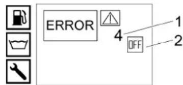
HD 9/23 GeTr1 + HD 9/23 DeTr1
MeTpneyn:105
Eyyunu:107
HDS 13/20 DeTr1
Mertpneyn:97
EyyunuEvr
HDS 13/35 DeTr1 + HDS 9/50 DeTr1
Meptnueyn:100
Evyunéyn: 102
HDS 17/20 DeTr1
MeTpneyn:100
Eyyunjeyn:102
OPTIONAL
Poiov: ABS arou HDS 1000
Túmôs: 2.013-093.0
Katnyopla ts uTojovadas
11
Aiaikaciec oumuoppwons
Mováða H1
Oepravticn oeprtavtiva
Ektnn oupnpwocovadac H1
MTIAOK EAEYXOU
EkTlunon oumuoppwocovadac H1
Δαφopoiaayyoi
Ektnonoumuoppwos Ap8.4nap.3
Epaepooueves npoiaypaepes:
AD 2000 Baoi Tou
TRD 801 baoi Tou
Ovopa kovotoinévou φopéa:
2014/68/EE
Egouoiobotn an to bioikntiko uoulaio.

H.Jenner
Chairman of the Board of Management
S. Reiser
Manager Regulatory Affairs & Certification
YTEUVOCTEXVIKOUpakEALO:
S. Reiser
Alfred Karcher SE & Co. KG
Alfred-Karcher-Str.28-40
71364 Winnenden (Germany)
Tnλ:+49719514-0
Φαξ: +49 7195 14-2212
Winnenden, 2023/01/01
TexviKa xaapaktnpiotiká
Peped npBbIM INoJIb3OBAHmEH yCTPOBCTI pOHTIte DaHHOE pyKOBJCTBO NO 3KcPIyTAUIN,
ДИСТВЕ В COOTBETCTBи C HМ N COXPAHNTE ERO ДЯ NOСпЕДУОJOERO NGNLOB3OBANHЯ INI CSDEYQUJOero ВlaDENBlaBa YCTPOCTBA.
Pnp6HApyuKhenTpaHcnpTOhX NobpeXdeHn cyapny npOHfOpMPOBaT TopROBO npdctABUTEN.
- Пи раснakOBьаннnpobерпсcodepxIMoeyvANKOBk.
- Pēpei nepbbl BBOOM B 3KcπnyatauHIO cneIyET o6a3aTeBbHO O3hAKOMTbc yka3aHMyMn ToTexNHKe 6e3oNaCHOtn No 5.951-949.0!
3aunTa OkpykaUoSei cpebl

Ynyakoboytble MATEPnIbI NOIaDIOCTBTOPHNOEpeaboTe. YNAKOBKY Heo6XOyUTNIINOPOBaT 6e3 yUepeBa DnA OKpyKaOH
cpebl

3NeKtpnueckne I 3eKtpnoHbIe ycTpoCTBa
yacto cOepkataeHHbIe Maepanbl,
nproDhBnIe DnA BTOpHNoH nepepaOTkn, n
3aHTAcY TAKNE KOMPOEHTN, KAC Batape.
AKKMyIaTOpbI INM MacNo, KOtOpBle npn HenpaBInbHOM ObpaueHm INI HeNadEkaeey yTuINa3uIN pnpedCTaBnOT NoteHuaNbHyU OAnCHocTb Iyra3DIOPOBaBnIKOkyKaHOu cpeBt. Te Me MeHee, DaHbIe KOMIOHEbI Heo6xoDMbI dIg nPpABInbHo paBObIy YcTOPiCTBA.YcTOPiCTBA, 0603HaueHbIbe 3TMM CnMBON, 3ApneEHO yTuINiHpoBaT BMeCte C 6bToBbIMN OTXoAMn.
Yka3aHnno KOMNOHeHTam (REACH)
Длноулсенийaktyanbayншфрмади кOMILOHENTXam.kaercher.de/REACH
DOnonHnTeJIbHaN INΦopMaun6 oXpAne OKpykaUoSe Cpebl
He donyckatb nonadaHn MOtOpHOro Macna, Ma3yTa,
DmEnbHorO ToTnnBa IN SeH3nHa B OKpyKaIOUc pCey.
BepehNo8y ByuTNInNpOBaB Otpa60taHoe Macno,
He HAnoc yUep6a OKpyKaIOUe cPee.
CNMBOJIbHa yCTpONCTBE

He HapBnTbCTpyo BOblIPOD
BbICOKIM DaBHeHnEM Ha IIODei
XKOBTOBbIX, BKNIOEHOE 3NEKTPUeCKOe
OobpyoBaHMe HnHa cMo
ycTrojCTBO.
3aunuAtb yctPoJCTBO OT MOp03a.

Onachocb H3-3a 3eKtpnueckoro
Hnpanjexnna. Pabotb cJneKTPnueckoN
CNCTeMOI MOyT BblONIHb TOJIbKO
KBaINuΦnUPOBaHnBle JNeKTPKn INN
ynOInHOOMoueHHn nepcoHAI.

OnaCHOCTbIIN3dOpOBBaI3-3aTOKcHbIX Otpa6oTAbWnra30B.He BbixTa b Otpa6oTAbWnra3bI.

Onachoctb oxorob o ropnyne nobepxno
NcnoJIb3ObaHne no Ha3HaueHnIO
Pnmueyaue
OmoCmch moIbKO K FepMaHui: YcmpoUcmeo npedycmompno moIbKO dRMOBUNbHOO (hecaumoharHPO) pexkma pa6mbi.
YCTPOINTOIINPMHEIRETC BYCLOBHXKOTDA Tpe6yETcOuNCTKa IORpAe BDOJpn OTCYTCTBN 3NEKTPOCHA6KHeH.
OCHCTKa:MaSHIN,ABTOMOBUNe,CTPOEHIN, HnCTpyMeHTOB,ΦacADOB,Teppa,CaOBO- orOpDHOHnHBENTAPN T.D.
ONACHOCTb
Onachocmbmpaemupoeahua!
Ipu unctb03aahhu na aemooanpaeeohbix cmahuaux uuu e dyyua onaChb6 3oHax
Cónbàdàüme coombemcmykoue npauna mexhukébonacchoum.
He doNyckaIte nonaHaHna CToHbIX BOD, coepKaaHX MNHepaIbHbIe MaCnA, B NoCyB, BODoEMbl INK KaHnI3aIIO. IooTOMy MoKy DBIrTaTeN INHua BlNoHNbTB ToNko B CneUHaBHX MeCTax, 6ObyoDaBHbIX MaCnoOTDeJInteNeM
IpeelbHbIe 3NaueHnna BDOCha6KeHHa
BHIMAHHE
3a2p3HeHHa 6oda
PfpeepemnHb u3Hoc unu omnoxehnue ycmpooumee
Iaeknnyamauuu ycmpoicme ucnnojaoamb monbko cmycu unu obopmhyo eody, komopar He npbebaaemnpedbblx 3auhenui.
Yka3aHnI NO TEXHnke 6e3oNaCHOCTN
ONACHOCTb
3Anpeaemc3Kcnyammuopeaibyycmpoucmeo 3akpbnbln MoneeHua
He xpaHume,he panaaumue u He uonlbyume duabnboHoe mnnpuB pradom C ompkbymbUm Oaem unu makmu npubopamu, kak neyu, bounepb, obohaopeaamenu mU n.0. comkpeu meum 3anaBuk unu mozm npoueodumb Uckpb.
Hukoəda He nepennonhme monnuehbiδak.
06nne noonxehn
CobIOdaBcoTBeCTByOUIne HauNOHAbhIbeHOBMb3aKHOdaTeJIbCTBaBOTHOUeHNJIKKOCTbIX CTpyHbX annapATOB.
CobIODaTb COOTBeTCTBYUOuHHe NaIOHOaNbHbIe 3aKHOHaTeNbHbIe NpeDnCaHnaHn pePDoTbPaueHHHe HecaCTHBx CnyAae PeYrPnPOBepRb pa60Ty KnuKoCTbIX ctpyHbIX AnnapaTOB npeybTat npOBepKn OOFPMJI B INCbMehOHm BNie.
HarpBaTeB yctpoCTBa npedctabnreT co6oI TOnOCHyO yctaHObKY. PeryAnho npOBepaT OTOUHYo yCTaHObKY B COOTBeTCTBN C HAIIOHAJIbHbIMN 3aKOHODaTEbHbIMN HOPMAMN
PIMMENMO TOBko K YCTOPOCTBAM C MOHTAXHBIM KOMNNEKTON Dnra paObTb B pekmne npaoo6ba30aHnna: Cornaco HeCTByUOuHn HauHOHaNbHbHm NIOJOKeHNr PnKOMMepeckOM IcNOIb3OBAHn MOUIN annapat BbcOKOro DaBHeHn DOJIKeH BNEPBbE BBODNTCBsCBA
3KcnnnyatauHn KBaHnHnPnpoBaHHbIM CneauanCTOM.CneauanCTb KOMNAHN KARCHER Yke oOcyeCTBnnpoee npeBoro BBOda B 3KcnnnyatauHn N 3aDokyMeHTPOBAnN 3OT npoucc.DokyMeHTauHNO MOxHO nOpyntb, OtnpaaBn 3anpoc napTHepy KOMNAHN KARCHER. Pn 3anpoce DoKymetaTnCneJeYk3aTa b HOMep Detannn 3ABoDCCKOH HOMep yctpoCTBA.
- PnIMeHIMo TOIbKO K yCTPOINCTBAM C MOHTaXhBM KOMNIIEKOM IIN paBOI B pEXmE napoo6pa3OBAHnro: ObaPaaem BHMaHHe Ha To, YTO corIaCHO DeNCTBYOUHMMaHIOHAnbHSBM NOIOKeHNrM yCTPOINCTBO DOJNHO nepINOuHcckn npOBepRTcKaBNHfUPOBaHbM CNEuAInCTOM IIN 3TOro cneyET o6pATITbC K napTHepy KOMNAHMI KARCHER.
3aNepeIaeTcB HOCNTb KAKeJI-NIO hMNEHnBA BycyptOCTBO NpHINAdJeKHOCTN.
KOMIIeKT WHH
△ONACHOCTb
Onachocmb Hecyaemho2o cnuya
Ha ebicokux ckopocmwxuHbMoaym
omcoeduhumbc.
Iraaemomobune c pa3peuHou ckopocmbio 100 kmu: uunb he doonkbu bmbcmapue uecmu nem.B cnayae noepexdehu, e3dymu/mpeunn ha 6okoo smke, ompbeo npfoum u m. n. uunbdoxknb bmy HEMeDneHHO 3aAmeHHei.
UHaH BbICOKO daBHeHn
△ONACHOCTb
OnachocmbmpaemupoeaHua!
- NcOnb3yTe TofbKOOpINHnAblbHe 1wAaHnB BbKoCOKO DABeHHN.
IINAHRTBbICOKO DaBnEHn I paCblntTeB OJIKHb COOTBETCTBOBAy YkA3aHHOMY B TEXHNcECKHX XapaKTepNCTKAX MAKCMaJIbHOMY N36bItoCHOMy pa6OeMy daBnEHIO. - 136eraute KOHTaKaTc XMMNueCKMNBeueCTBaMn.
PpOBePnTe 1nAnHn BbICOKOr DaBHeHHn EekDheHO. He nCnOJIb3yIe NpeReHyTbe IuHaHRn EcIN BnEN BHeUHn CnO NPOBoJOnK, To IuHaRbICOKOr DaBHeHHn 6oBHe He nproDoE K nCnONb3OBaHHo.
HeIcNoJI3yTe IJMaHr BbICOKO DaJIbNEHc O nobpeXdHbOH peB60B.
KpoknadbAbaTe 7nAHI BbICOKOra DabNEHnA TAK, 10cb6Ie noHb34 b6IIO nepeexTaB.
HeNCN0b3yIte ⅢaHr, KOTOpB 6bIpa3dABnEH BCNECTBn Hae3da, a TAOKe nepeDabNeH ININ NEpeKaT, DaJIe ECNI B3aYalbHO OTCyTCTByIO TcNDb NOPEXDEHNI.
XpaHnTe WJNaH BbICOKO DaBHeNIAK TcTb6b He NDoBeRaTe bE moEAHHeCKm HApY3kAM.
PnHcHn DeHCTBn
Hacoc BbICOKOra DabEnno pINBODITcB 1eIeCTBnE OI dN3eNbHO DBrAteTcN C NOMoCbIO npOMeKyTOHOpeDyKTopa.
Mekdy BAKOM C NONNAKOM HACOCOM BbICOKO TABNEHNO BODA HARPEBAETC TENNOO6MeHHNKOM, PACNIOXeHHbIM KHOType OXnKaDeHIN DBVATeJIA.
PnpnepbIaHmCtpynpepnyckHKnanaHpepeKIOUaETcBPEKMM63HaNPHOINPKUYIaNBOJb,INBraTBeTbpnoDpKaet pa60TaTb HXONCTOM XOy.
B0aHnapeBaTcC nMOoUsbOropeKInHaXnIOkOM TOnPiBe, HxOraUeIeNc HA STOPOE DABNeHN.
B-BeJmHOpRoeHbOBoIbKoBoEdoabnTcY yMRHtTeBbHaa JxMDKoCTb.
ToIbkoHDS9/50,HDS13/35(onuIaHDS13/20,HDS17/20):Pa6Ooee daBneHne MOxHO BbIpaTb nopeCTBOM peryInpOBKn YnCna 06obpOtOB DBrRteRn.
ToIbkoHDS13/20,HDS17/20:HacocBlycokoro DabJIeHnRA BCaCbBaET MOOJee CpeCTBO. IponOpunHO MOUoero CpeCTBA B OBe MoXHO HACTPANBtCB NOMOuBo DO3NvUOyoo KJNAHAI
ToIbKOHS13/20,HDS17/20(onuHMOHTaXhBIOKOMnEeTJyHUYTOKeEHcOPHkoBTopraueBOoD.
ToIbKO HDS 13/20, HDS 17/20 (Onu): MoHTaXHbI KOMTKeT IJN OUcNTK IN DeuINHΦeKm npAM.
PpeoXpaHnteIbHbIe yCTpoIcTBA
Ppeoapanentbhe yctpoCTBa cnykTnna3aunTb noIb30aTeNa. Ix 3anpeaaetc oTKIOuOaTb mnn uHTnpoBaTb.
ABapnHbI BblKlHoaTeJb
ДагиеменгогоТКIOHUENHBE XECФYHKIN:Hakatb abarIMHHB BbIKIOUOATEb.
PpeOxpanHtEnbHbBbIKnOaTeN, PpeHra KpbIka
- UcTpoIcTBo MOKHO BKNIOaTaB TOJIbKO pN3aKpbITOn nepdHeN KpbIiKe.
EcnnepeepnKaOpBbAeTcBOBpEmpaOBo,ycpoIcTO BblKnUOaTeCn 3aropaTeCNHdkATOppeepnKpbuKn/abapuHOroBblKnIOEHN.
NepenynKnoKnaan
EcnnypHNOCTOENPacBnINTEb3aKpBT,OTkpbBaETcpeNpyCKHOKNaANHACOC BICOKORO DABIEHNEIpeKaeUHBAETBOy 6paTHOB 6BakCNONNAKOM.TAKIMOBpazOM npEDOTBpaAaTecnpBeBtuHHeDONYCTMOrO pa6oOerDabHne.
TolbKOHD13/20HDS17/20:PnCHKHeHHI paccxOa BOblcNOMOJIbEOpyJIToPA DaBHeHHI paacXoHa NtICTONe-PacBbJIITNE OTKpIbAeTCr nepenyCKHOKnahanHuaCTbOBbemaBOD Bo3BpaAcTe B6akCnONNAKOMIN6akDN BObl (B 3ABNCUMOCTN OTNOJKeHHI WaOpBOrO kPAn dNpeKNIQHeHHOsbPaHOrO NOTOKA).
- PeneyckHO Knahan OTepyIPOBAH onlonmbupoBa H aBoe. HaCtpoKa OCyueCTBnETCaTOnbKO cepBCHOn CnykBoi
PpeoXpaHntbHbI Knaan
PnpdoxpanenBnKnanAnOTKpbBaetcB Cnyae HncnpaBnOtn npenyckHOro KnaHaH NIM MAHOMETPnEeCKTO BkIIOHATEJ.
PnEdoxpaHHTeBHLKnAanHactpoen H onlOmbipoBaH hBaObe.HacPoJaK npOn3BOITcCepBCHOn Cnyk60i
KoHTpOJIb 3apAkn aKKymIyIaTopa
- Pn HeOcTaTOHOMyOBHe 3apJHOrO TOKA B reHEpatope dna 3apJDKN AKKMyrTota yCTpOHTBO BbIKNHOaETC.
- OTo6paKeHHe HEnCnpaBHOcTn: ERROR 1
KoHTpoJIb TemNepaTypbI BoDbl Ha BXOe HJH
oxnaekdaioueBodbl
EcnTemnepaTypaBodbHaBXOde npeBtuAeMaKcMmaBHO donyCTmoe 3HaHeHHe, yctpOCTBOOTKIOUaTcR.
EcnT MnepaTypa OxnaJaoue B0bl npBbJaaeMaKcMmAbNo DOnyCTMnOoe 3HaHeHNe, VCTPOCTBO OTKNIOUaTeC.
- OTo6paKeHHe HeNcnpaBHOCTn: ERROR 3
CnTeMa npdoxoaneHHOT OTCYCTBNN BOdi,6ak cNONJABKOM
CnTeMa npdoxpaHEnr OTOCTyCTBn B0bl npDoTbPauaet BKNUeyHne DnBraTeI npHEOCTATKe BObl.
- OTo6paKeHHe HEnCnPaBHOcTm: EROR 4
Topenka B chteme npedoxpanenr OTOCTYCTBNO BObI
- YcTpoIcTBo npedoxpaHEHnO tOTcyTCTBnB BObl (biknIOvateNb rnpopene) npenrTCTByET nepepeby ropeKn pni HeocTaTke BObl. Fopenka 3anyckaeTcToIbKO npn DoCTaTOHOM BODOCa6KeHHn.
- OTo6paKeHHe HEnCnpaBHOcTn: ERROR 5
MaHometrpueeckn BbIKIOvateIb/ BKNIOvateIeN rIuOpoe
KOMHNAHAA MAHOMTPNYHECKORO BbIKHOATenB BKNIOAteTn RINPOPENE BbIKIOaueHaRpeBaTeNb PnHEDOCCTAOHOM KONJYCECTBE BObl NmYTEKe.
- OTo6paKeHHe HeNcnpaBHOctM: ERROR 5
KoHTpOJb yPoBHa TOnnNBA
- 13-3AOTCYTBNA TOONJIBAI (TOONJIIBHBI 6AK PYCT) YCTPOUYCTBO OTKNIOUaETC.
PpumeyaHue
Pocedcmeom bsklouenHbcklouheny ycmpoueeaeoh npodonkaem pabommb meeyehue 5 muhm, nok monnubhui bak he ydeem tonnohcnoynycmbm.
B cyuaeBa6paote DaTnka TOpNBA VCTOPNCTBO BkKnHQAETC.
- OTo6paXeHHeHcnpaBHOCTn: ERROR 6
DabHHeMacnaBdBnraTeNe
MaHOMETpHecKn BblKnOHTeNb OTKnHOaET DBrATeNb, KOrDaBaBHeHE CTAHOBtC HKeMHVMAbHOrO DaBHeNMaCJaBDBrATeNc
- OTobpaKeHHe HEmCnpaBHOCTn:ERROR7
OrapnHnteIb temnepatbyt OTPaobotuxn ra30B
OrpaHHTenb TemnepaTpyb Otpa6oTabnx ra3OB OKHouaert ropeNk,ecm TemnepaTpyo Otpa6oTabuNXra3OBCTAHOBITcCNKOM BbICCKO.
- OTo6paKeHHe HEnCnpaBHOcTH: EROR 9
KoHTpoJIb TemnepaTypbl rOpENKn
EcmtemepaBoDbHaBxOeRopeKn npeBbIwaMaHcMaaNbHOOnyTcHMOe3HaHeHne, yCTPOCTBOOTKIOAaETC.
B Cnyae c608 B pa60e datuqka temnepaTybY yctpoTcBTO kTNKoAuaT roPENKy.
- OTo6paXeHHe HEnCnpaBHOCTn: ERROR 10
Pene KOHTpOJI pIaMeHn
Pene KOHTponla\PaHemOtKIOUoAET ropeNKy B cnYae HeNCpABHOCTN ropeNKi.
- OTo6paKeHHe HEnCnpaBHOCTN: ERROR 11 nJn 12
OTKIOUOHEHNEIOIeTeHNNYcTaHOBJIeHHOROBpeHNIrTOBHOCTN KaObeTne HENpePBIBHNO paObToI
- No vcteyHn yctahOBHeHHOro BpeMeHH roTOBHOCTN K paOte Hn HEnpepeBbHn paOto b(45 MNHT) 3JNeKTPOHKa BbIKIOHaET yCtPOCTBO (3ABODCKA YCTAHOBKa).
- OTo6paXeHHe HEnCnpaBHOCTn: EROR 14 nn 15
PpeoXpaHnteBbHbIΦnKcaTOP
PnpdoxpanhtenbIhpnKcataop na yHOMNCTOte-pacnbntene 3aunuaeT oTHENPMBOBHLBOHR BKNUQEHN yCTPOCTBA.
063op yctpOcTbA
OncanHe yctpoicTba
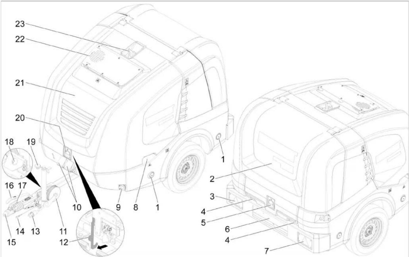
① OTPaKaTeNb (c o6eNx cTopoH)
②BaHnKa KpbWka
③ Kom6HHPOBaHbIe foHApn TOpMOxEHn/3aHnHe raBaHpNtBHe foHApn cyKa3aTeIeM NOBOPota (HafeBO)
4BbOuIaHaRa npn 3akpbItOn 3aHneKpblWKe
(5)ФИКСАТОРЗАнг КрБИKKN
6HOMePHOH3HAKCIOCBETKOH
⑦ KoMbHnHpOBaHHbEΦoHApu TOpMOxEHn/3aHnHe ra6apHTbEΦoHApuC yKa3aTeNEM IOBopoTa (Hanpabo)
3axbaTHbI na3 nepeDne KpbIuKn (c06eX CTopoH)
⑨ RaapnTHbI ΦoHApb (c o6eHX cToPOH)
10POTNBOOKATHBn ynop
(1)Onophoe koneco
13aXbBaTHBle KpOKn
13 WTekehoe coeHHeHHe 3nemHToB OcBeHn TpaHCnopTHOro cpeCTBa
④CTpaxOBOUHbI TPOC
16CTOARHOHbI TopMo3
(17)Pbnyar cquenneHn
18 DepeKaTeB nIg WTeKePHoro coeDInHeHn 3neMeHTOB OCBeUeHn TpaHCnOpTHOrO CpeCTBa
20ФИКСaTOpпepeДнeн КрБИКИ
(2)Передимя кршka
2 OTbOoTpa6oTaBux Ta3OB
②Побемнhoeушko
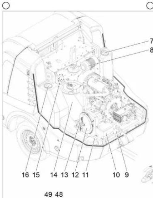


1N3eBbHbI DBHrTaTeB
②PomexyToHbpeDyKTop
3 Hacoc blycokoro daBrenn
④ PpeoXpaHHTeBHyb6nK rOpEnK
⑤BblnyckHaa Tpy6a
⑥ KomneneHnoHHb 6aok nla oxnaKdaoueennkoctn Dniratela
⑦ OTBepCTneIaTExnueckoroO6cnyKuBaHna6aka IINBODI(cNEBa)
8B03nyHbHnHbTp
⑨BaOIOckKa Ta6nHka
10AkkymyITOP
(1)Homep waccn
(2)HarheTaTeNb ropelkn
③TOONINBHBHnHaCOC
14PtoUHbHarpeBaTeB
(1)TpaHcΦopMaTOp 3aKmraHn
16 OTBepCTneIaTExnueckoroOobnyKunBaHna6aka IIN BODbI (Cnpaba)
⑦ BaKДЯ MOKUэro CpeDCTBa
18 ΦHbTp Ha BcabBaIOeM WnaHRe DnMaHOJIeO cpedCTBa
19 BcacsbIaOuHmIaHrIaMoUeero cpeCTBa c daTukOM ypOBH
20 Do3nyuian Knaan MOoOero cpeDcTba
20CTeKIINXpAHeHpyHOrIONtOTePapcnblnten
② OTeck dIa XpaHEnI cTpyHn Tpy6K
(23)Шанг ВсICOKOTO DAВLEHIN
24)Bapa6aHnIyIbnHaRbIcOKoRo daBneHn
(2)AbapnHbBbIKnOaTeJb
26Bapa6aH nIy IHaHa Hn3KOrO daBHeHH
27 EMKoctb IaIy mMyHHTeIN BODbi
(28) Baik anHnФри3a
293aannBHOHnATpybok TOnnnBHorO 6aka c qnilbtpom
50単ロ�営KpahCINCTeMbI3aunTbIOT3aMep3aHnH
31 INHdkaTOp yObHra 3aOnJIHeHnBa 6aKa dIy BoDbI
32 BaK c nonnabkom
33 YnpaBHeHne YacToTOn BpaSeHHa
34 3aJIbHoe OTeBepCTne 6Ka c nonIaBkOM C KpbIuKoI/6apauKOBbIM BHTOM
35 3aJIbHObe OTeBepCTne JnJxNdkOrO yMaIyHTeJIa
36単apOBoi kpaH nIpeKIOueHnO o6pTHORo NOtOKa
37PacnpedenntelbHaKopobka
38 3aunTHbIJIcT (cnpaBA)
39 3aunTHnIcT (cneBa)
BnycknoI kpan 6aka IJN BObl
4CnBHOK KpA
42 ⅢnHmPoMo3o3aunTHOH CnCTeMbI
43BodonpoBODnHbIshaHr
4B OdaHOn FmNbTp H aXoJe
45MaHOMeTp
46 POna aHTnFpna 3nn npKOBoHoe nnoKeHne IINr coeHNHe Hn3KOrO daBnEHHa GEKA
47 O6paTHbI TK aHTHpN3a Nn npKIOBOUHOE NOOKeHNE DnA COeHNHeNBAICOKOr DaBHeHNA
483amok6aka
(49)Pahenb ynpaBneHn
Panaelb ynpabJIeHnIa
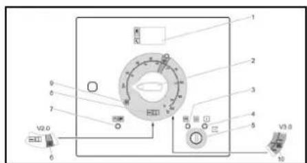
0/OFF = BBKJ.
①DinCnnei
②BbKIIIOuATEnb yCTpoHCTBa
③ KOthpOlbHaa nAmnoUka npedBaPntbHornporpeBa (kpacHa)
(4) KOHPTPOJbHaJaAMNoQKaTOrOBHOCTN K 3Kcnnyataaun (kpacnha)
5BaMKOBbI BbIKIOUaTeNb
6 PexmpaObTb《YHHTOKeHeCOPHKAOB》V2.0 (onuHnHDS13/20,HDS17/20)
⑦ KohtpOblHnA lamnoQka, npeDnHa KpbIshKa/ abapnHoe BbKIOUChEne (KpaCHa)
(8) Pēχιμ παδόβτβι «Fρογαι/xoπούηλα Bóda» (0-100 °C)
9 PexMM «3aunTa oT 3amep3HnA»
10 PexMM pa60tby《YnHHTOKeHne copHnKOB》V3.0 n V5.0 m npo06pa30BaHnRA(onuHnHnHDS 13/20,HDS 17/20)
PernctpaounHbIe DOKyMeHTbI
PernctpaunOHHe DOKyMEnbI yCtpoCTBa xpaHrTcB ⅢkaФу nEeKTOoBOpOBAHn. UKaΦ zanept dIra TpAHCNOPTPOBkN.
OTo6paXHeHnE HopMaJIbHoro peKIma

① TOnnBbHbI 6aK (MHdNkauNoHHa nnHaKa)
② DBnraTeBkN. (ON) nnn DBnraTeBbIKN. (OFF)
3 BaK dIy JxNkoro yMnHrTeTEna RM110/6ak dIy MoOuero cpeCTBa CHEM (OK/empty)
4 Cuetukacobpaobtbi
⑤ Yacbpaobtbo do cneDyioo cebpncHoro 06cnykBaHHa
PpumeyaHue
Houkaa6aka dna MOoese cpecme
Ombpaema, moIbKO eCnu paHee 6ak dna
MOoese cpecme 6bl paNo3HaK KAnnonocMb
3anonHHb.
B HopmalbHOM pexume paobmy Ha duCnnee
cuMeMb ynpaBneHn NopepeHNO omObopaema
Cedeyoua unHfopmaa.
HopMaHbHbIpeKumpaOmbi
Cepuechoe obcnykuahe: Pabombl no mexhueckomy obcnykuaehuio c hacmynueum cpokom, npoobumbecepechou cnkybo (cm. YXod u mexhueckoe obcnykauehaue). Ecnu cneydem npoeecmu heckonbko paobm no mexhueckomy obcnykuaehuio, mo OHU omobpaaxaomna o uepedu. Ecnu cpoK npoeedhuapombl no mexhueckomy obcnykuaehuio He hacmynl, mo daHnra unhopmaun He omobpaaxaemc.
HeucnpaHocmb:Bo3Hukwae HeucnpaHocmb (CM. “POMOe e cnyae 8o3HukHOeHue HecnpaHocme). Ecnu o3Hukno HeckoBko HeucnpaHocme, mo OH omobpaXaONc no Opepu. Ecnu HeucpaaHocmo omycmeyom, mo omobpaXaemc cnedyoua unfOpmaun.
OTobpaxKeHne 3aunTbI OT 3aMep3aHH
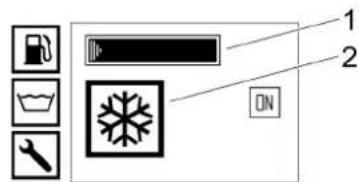
① TOnnBbHbI 6ak (mHdNkaUHOHHa nnHaKa)
②Реким«3aциТаOT3aМерзанЯ"
BbICOKoHaNoPbHnNtOneT
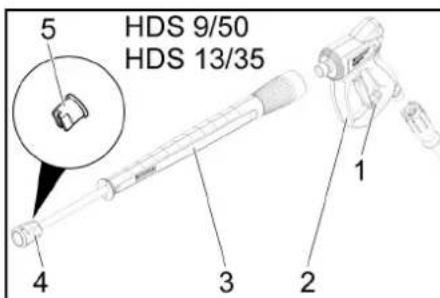
1PepdoxpaHnteNbHbHnKcTOp BBICOKHOANOPHOrO NCTOneta
②BbIcOKoHaNoPbHbI NCTOeT
③ CtpyHna Tpyka
④HakdHaayraika
⑤ Conno 正bocokoro daBneHn
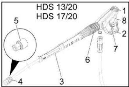
1PepoXpaHntBnHbHnKcAtop BbICOKHOANOPHOrO nCTOneta
(2) BbICOKOHAnOpHbI NmCTOnet EASY!Force
③ CtpyHnA Tpy6ka EASY!Lock
(4) HakuHua raiKa EASY!Lock
⑤ Conno BbICOKO daBneHn
6 PerynopBka DabneHn/obema Ha nCTonete BbICOKOro DabneHn
7PpeoXpaHntBbIpbUar
⑧CnysckoBoBpyChar
BbD B 3KcNpyaTauuO
△NPEDyNPEXDEHNE
Onochcm bpmaepoaoaH!
Ycmpoucme, npuaednKocmu, nodeodaae nuu u coeduHemnbIhe 3neMeHmbl doxNbI bmb e 6eaynpchom ccomrHu.
B npomueHOM cyhae ycmpoucmeuonl30amb HeJIb3.
YcTaHOBka N BbIpaBHHBaHne ycTpOncTba
BHIMAHHE
Ipepeee ycmpoicmea
136eaime nepepeea ycmpoicmaa. 5bepumc, mmo meco ycmahoe kdoomamoh npoeempueaem.
BHIMAHNE
Onachocmb Heucnpaehocmeu noepexkdehu ycmpoicmea.
Peped 3cknnyamaute ycmpoiacmoe donjno 6bmb bypoheHero zupzohmanbho.
Bb6paTb MeTO yCTAOBn TAK, YTO6bI He nepeKpbBaNcB OTBePCTne DnA OTPa6oTaBuxn r308.
1. 3aФИКСИРОВАТБ CTORHOUHbI TopM03.
2. OnycntnbynopHoe konecocnmooubIpykOaTKn
3. OTcENITb cTpaxOBouHb TpOc OT TaRaAa
4.Pa3eDINHTbTteKePHoe coeDInHeHne 3neMeHTOB OCBeEHHep TpaHCnOHTHOpeCtBA HzakpENrB B MecTe DnRAxAHEHHHaBnNE.
5.3aФИСКИРОВATb yCTPOICTBO IPTOBOOTKaTHbIMN yOPIAMN
6.OTcENMbTgA.
7. BbipOBHrTb yCTpOHTBO C NMOUHO yNOPHORO KOJeca Ropn3oHTaJIbHO.
OTKpbIbAHne/3aKpbIBaHne nepedne KpbIuKN
- HaxaTb Ha qKcTOp nepdHe KpbIuKn. TpeDnHg KpbIuKa oTKpbIbAeTc, 6bp3y uIb.
- Pa36nKpObaTb KcNcPnyoUHm KpOK,NotaHyB 3a Hero. IpeDnHg KpbIuKa aBTOMaTHueCKn OTKnDbBaETc BBePx. Pn3aKpbIbAHm CneDHTb 3a TEM, YTObI KpOK 3aΦKcNcPBOAJIcR.
Buratelb
- PpOeBnTb yPoBHeMa nBa BdrBrateNe.He 3KcNpyaTnpoBaT yCToPOnCTBO,ecmYpoBHe MaNa onyctnIcn Hnke OTMeKnr 一 _ 出 MIN).
2.Пи Heo6xOДIMOCrI DoJIITb MaCNo.(cM.«YxoI n TexHHeCKoe 06cJyKINBaHHe»)
PpomexyToHbI peDyKTop
- NpOeBbIeY pOBEHbMaJcHa MaCNOpEMHOM cTeKNe npOmejXyTOHOro pEyKTOpa
- Pn Heo6xOJIMOCN DoJIntb MacNo. (CM. «YxoI n TexHHeCKoe 06cJyKINBaHne»)
Hacoc BbICOKO DaBJeHn
- PpOBePbIb yPoBeHb MacNa Ha MacnIaHOM BaKe HJIHa N3MePteBbHom IyTe HAcoca BbCOKOro DaJIeHrA.
- Pn Heo6xOJIMOCN DoJIITb MaCNo. (CM. «YxoI n TexHHeCKoe 0cBnyKINBaHne»)
OxnaKaIouaJKNKoCTb
- PpOBepnIb yPoBeHb OxnaXdaIOuee XKnIOcTn B KOMNEHCaIOHOHGN BaQne Ipn XoONODHom DnBraTeNe. YPoBeHb XKnIOcTn DOJIKeH HAXOINTBc MEKdy OTMeKAMN MIN IN MAX.
2.Пи Heo6xOДMnOCTH DoJIITb OXnAaJauOyU KIOKCTb.(CM.《YxoI N TeXHnHeCKeO 06cnyKBAHae) - ПоверпьКоюльтраию AntифразиаВCOКИЕСАЦМОНБАЧIKE.
- PnHHeo6xOaHMoCTn DoonMb aHTnΦpN3. (CM. «YxoI nTexHmCheKoe o6cnykBaHne»)
Bo3dyhblnIbTp
- PpOBepntb Bo3dyHbHn FmIbTp.
2.Пи He6OxDMMocTH OHTHb/3aMeHITb B03yUHbФnIbTp.CM.YxoI TeXHHeCKoe 06CNYKBAHNE)
3aHbHaHe Kdkoro yMaHTen
KJDKYM YMRYHTENb BICOKO3ΦFKeTINBENI npedOTBpaueHnOBpaBOAHN 13BcETKOBORHO HetaB HARpeBaTeBHOM 3MeBEHKePn INONb3OBAHIN JECTKO BDOJPOBOHOHO BObOHO doBaBnE Tcno KAnE B PnEMHb KaHaJ6aka C nonNAKBOM.
Ha 3aBoJe OIOIPOBKA yCTaHOBNeHa HcpeHIOK JOEeKTKOCTb BOJb.
PpumeyaHue
Побнанурахкова xukdo so ymuaquemera exodum e KOMNPEK mocmaBu.
- OKpbItb 3aJIbHoe OTBepCTHE dIy JxIDKofo YMRJUHTEN.
2.3aNTbKmKmymrHrTeNb
3.Akpblb 3aJIINBHOE OTBepCTHE dIy JIKDKOY MMRHTEN.
3anpaBka TOnnBOM
ONACHOCTb
Henodxodraee monnuo
Onachocmb 83pb18a
3anpaenme monsko duhenhoe unu nekeo komehoe monnueo. Henodxoadue uobl monnuea, makuie kak beshunucnohbaemb 3anepeho.
PpumeyaHue
Ppu ucnno3oaaHn 6duo3enbHoo monnae B5 (e coomeemcmeu c epeoneckum smaHapmom EN 14214) He mpe6yemc c6b0dHeue oc6b8x ycooeu
3cknnyamaa,06cnnyuaaunu mexhueckux paobm.
PpumeyaHue
PpuucnoIb3oaeauu 6duo3eIbHOzo monnuea B6-B20 (8 coomeemcmu c eeponeukm cmaadpom EN 14214) mpebyormepe no nepeo6opyoaeuho du3eIbHOzo deueamena. Taekhe neo6xodmo Co6nIOdAmy cnooea kcnnyamauau, cepeuchozo 6ocnyuaunu u bInonHeu mexHueckpu paOm. O6pammebc K opouanbHomy dunepy Yanmar.
- OTKpbTb KpbIaKy 6aka.
- 3aONIHbTmDnBbHbTOMTNIMBOepe3 ROPONHYTOHNBHORO6ba.
- 3aKpbITb 3AMOK 6aka.
- BbItepeBbIteKuee Dn3eIbHoe TOnNIMBO.
3aJIbAHHe MOUeRo CpeDCTBa
ToIbKO HDS 13/20, HDS 17/20:
ONACHOCTb
HenpuzodHbIe Moouue cpedcmea
Onachocmbmpaemupoeahua
IcnoIb3oabmbonbko npodkmbi kOMnHaH KARCHER.
Hu 6 koem cnyaee he 3anaumb pacmeopumenu (Hapmep, 6eh3u, auemoh, pa3kxumenb). H6eamnb nonadunu en a naa u ha koxy. Co5nodamb yka3aunu no mexnuke 6e3onachocmu u yka3aunu no npumehnuo om npou3edumena MOoojeo cpeoema.
PpumeyaHue
Karcher npednaaem uduayalbHbI
accopmmeHm mooux cpecmu u cpecm no
yxo. Baw dunep bedyem pad npokohymupoeamb
bac.
1. 3anpBAKMOOzIMcpeDCTBOM/3aMHeMOoIero cpeDCTBa
AkkymyTrop
Ppumeyaue
BcmahOpmmKoMnNkmaaUy cmpoucmeO chaoHehoe6CnykuaebMbI AkkymYrnapom.
Yka3aHnno TexHnke 6e3oNaChocTn no o6paueHHo CakKymyIaTopamn
Pn obaeHnn cakymyaTOpbHm6bTapeMn cneJyT coBIOaTc neDyIOuNe npDeynPeDInTeNbHe iykA3AHN:

CobnIodTa yka3aHnHa aakymnyTope, B HcTpyKuImbOcNpb3oBaHm n pykoBocTeNo 3kCnPyataun TpAChncOpTHoro cpeCTBa!

Mcnonlb30BaTb cpeDCTBa 3auNTb rna3!
He IonyckaTbTeJen K 3eKnTpOnity n AkymyTnTopam!
Onachoctb B3pbBa!

Orh, nckpbI, oTpkbTbI CBETn KpyHne 7aanepeHb!
Opanchoctb nonyuHnXIMueckoro oXora!

PepBar nOMOBb!

IpeynpexdHne!

YTNn3aunr!
He BbIbpaCbBaT bAkkyyMnTOp B MycOpHbIKoHTeHep!
ONACHOCTb
Onachocmb 3pblea!
He Knaemb UHcmpymenbl uUu noo6hble npdeMembl Ha akyumnyamop. Oanachocmb Kopomko0a 3aMbkaHua u e3pbja.
△PENDYNPEKDEHNE
Onachocmb ompaaneHua!
Hu e Koem ciuyae He donyckamb KOHmakma paHb co ceuHcM. Pocne paombbcamapemMu ceedaMbmb pyku.
△PENYNPEXDEHNE
Onachocmb nonyuheHu xumueckoo oxo2a!
Ppu paBomax c 3eKpmponum u cnoNb3oaeamb Kucnolomocmoukue zauuHbte oUk, nepaamku u fapmyk.
3apdka akkymyTopa
ONACHOCTb
Onachocmbmpaemupoeahua!
Cobnodamb npabuna mexhuk6e3oanoccmno 6opauehu c akymnnapmhu mu 6amapemu u pyko0cmeo no 3knyamauu npou3o0dumena 3apnoo ycmpoumea.
3aJrKamb kAkyMnIap monBko c moTObu cooemeemcyeuooe zapadnoe ycmpoucema
1. OToCoeHNHTb KJEmMbI aKKyMnyTOpa.
2. CoeHINHTb NIOXHTBbHbI npBOd 3apdHoro yCTPOHCTBa C NIOXHTBbHM NIOHOCM akkymyTopa.
3. CoeHnHTb OTPNaTeBnHbN npBOd zapAnHoro yCTPOHCTBA COTPNaTeBnHbM NIOKoCOM aKKyMnyTOpA.
YCTABINTB cTeBOUIITEKEP IN BKNIOUYTB 3aPdHoe 8yctpoNTbO.
5. 3apKaTaB aKKMyTApHy6bTaapeo C HAMMeHbWe Bo3MOxHOcNIOI TOKa 3apKn
YctaHOBKa BbICOKOHaOpHOro NcTcToJIeta, cTpyHoi Tpy6Kn, Conna Ni ShnHaRa BBICOKORO DaBJIeHnA
- CoeHHHTb CTPyHHyTO Tpy6ky C pyHbIM
NCTOEtOM-pacbJIInTeJIeM. - BpyuHryo 3aTMyHyb pe3b60Boe coeDnHeHne CTpyHNO Tpy6Kn.
- BCTABINb COIIO BcICOKO DaBNeHnB HAKINHyokaiKy.
- YcTaHOBnTb 3aTMyTb HAKnHHyrKaNy
- NpOcOeMnHb 5uHAFBbICOKOFO daJIeHNIKA BcKoKOHANOPHO MYCNOTJEY.
BHIMAHNE
Onachocmb nopekdehura!
UJIHbA bIcKoZO daJeNHeu HaxOdumcno daeNeHuEe.
BceBa noHocmbpo pa3MaMbIaMb 1nHa 6bICOKoO daJeHau.
ToIbKO HDS 13/20, HDS 17/20:
PnpuMeaHue
CucmemA EASYLock b6cmpo u hadexho coeduHrem KOMHOHeHbIe cce0 3a oduh obopom pe3b6oeou qacmu.
NATpy6ok dIy noDBoDa BObl
PapameTbI noKJIOUHNY kya3aHb I pa3JeN "TexHHeCKNE XpaAKTEpMCTIKN."
- PamaTbB ODonPObDbHbI ShaHrC bapaBaHa Dla IaHaHaI N oOKnIOuHTb K cToTHNuKy nOaAn BObH (HapnIMeR, BODonPObDHOmy KpaHy).
3anJHHeHne6aKaIbOdbI
- OTkpbTb KpaH 6ka DnB BoDbI.
- Pa3MOTab BODONPOBDoHbI ShaHrC bap6BaHa Dla IaHaHa I NOkKIOuHTb KcTOHky NdoaYbOBoH (HanPIMeR, BODONPOBHOMy kpaHy).
- OTKpbIb IINHIO NOaU WBObl. BaJnBra BODJI 3aONHHeTcYepe3 BaK c nonNaBkom. Nocle 3aONHeHnBAkOB dNRA BObl. nonNaKBobII KAnAH B Bake C nonNaBkom 3aKpbBaetc.
- NpepeKpbTb noauy BoNbI
- OTOcoeIMnHTbOBDOPOBODNbIuANrOT TOHcNHaKIOADaHBOBdI.
- HAmoTaTb BODOpOBoDHyB MHaHnHa 6apabH DnA mHaHra.
YnpaBneHne
△ONACHOCTb
JNeKoBocnnaMeHouuecXudkocmu
Onachocmb 83pb18a
He pa36pb32aebmb 20pouue xudkocmu.
△ONACHOCTb
Pa6oma 6e3 cmpyuHou mpy6ku
Onachocmbmpaemupoebahur
He ucnonb-yame ycmpoacmeo 6e3 cmpyho mpy6ku.
Neped kaxdbim ucnonb308aHuEM npo8eprume,
HadeXHo nu ycmaHOeneHa cmpyHnA mpy6ka
Pébóboe coéduhne empyuohm py6ku doxnKHO 6bIbzmamHymo on pyku.
△ONACHOCTb
Cmye oobbebcokoo daenHua
OnachocmbmpaempuoeaHua
3anpeaambcbpkaocpaambcnyckoeu u npdoxpanumebhui pbaaue a paoboy nonoKeHu. He npb3o6aambcbe bokohanopbHm nuomlemom c noepekdeHHbIM npdoxpanumebHbIM pbuaom. Peped hauanom niobx paobm ha ycmpoucmee cduunym bpdoxaHnBbI pfukcamop ebicokhanopno nucmonema enpeb.
Джрхь веблесонанорьи nucmonent ucmpунуюmpубiy oboumu pykamu.
BHIMAHNE
3Kcnnyamaaunc nycmbim monnueHBIM 6akom
NoepexdeHue monnuehozo Hacoca
3KcIpyamaaZy cympoCmea C yncbIM monnueHbM 6bakom zanpehence
OTkpBbAHHe/3aKpbBaHHe
BbICOKOHaNoPHoro NcToJeTa
- OtkpbBaHne BbICOKOHAnOpHOro nCTOneta:
Hakatb npedeoxpahnteHbHn cnyckoBo npuHa - 3akpbbAHAHBe BICOKOHAnOPHORO NCTOJETa: OTNcTnIb npeDoxpaHITnbHbI N CNYCKOBB pbMaHr.
3aMeHa conna
ONACHOCTb
Onachocmbmpaemupoeahua!
Bbocokhanopnb nuonmeh haxodumcno od daenHeuem.
Ipepe 3aemoho conna bblnoumb ycmpocmeu o HaxmuMb bblcokohanopbH nucmonem, noka daeneHeue e ycmpocmee nonHcbmbo He c6pocumc.
- BkIOHHTbYCTPOIcTBNOHAKIMATb BbICOKOHAnOpHBNNTOJE, NOKA DaBHeHNE B yCTPOIcTB NONHOe He C6pOITcN.
-
3a6nKpOBaTB BbICOKoHaOpHbI nCTOJeT,
cDNHyB npeOxpaHHTeNbHbIΦNKcaTop BnpeEd. -
3aMeHHTb cOnnNo
Poaay BoBbI
Boda moXeT noDaabTaCnMo 13 BHeUHero nCTOuHnKa, nMo 13 BHTpeHHx 6aKOB dIra BoDbl (2 x 250 n).
単ロBOK pAN DnI nepeKnIOueHnO 6paTHoro noTOKa
- NpOxKeHnepaTHBHO HApBaNHeHbDBeKHeHn: O6paTHBaOHaC0Ca BcOKoTAbEHHn pnpOTkpbITompepeyckHom KnAnahNoctynaT B SaC nONPAkBOM.
IpumueaHue
Ecnu e daHOM nonoxeHH uapaozo KpaHa pyHou nucmonem-pacbInumen3 3akpbIaemc, mo u3-3a nepeapeBa ycmpoUcmeo Mokem bIKIOUumbcra Ype3 HEckOko MUHym (CM. «POMOuI npu HeucnpaHocmEx/ERROR 3').
PONOKeHMe NepEnDmKnyrnpHO HnPaBNeHIO DnBHeHn: O6paTHa B0Da HAcocA BbICOKo DABeNHe pRn OtKpblOM nepENyckHOM KNaIaNHe NoCTynaET B6ak DnRA B0Dly.
Iopaya BOdbN3 BHeuHero NCTOuyHnKa
1.YctaHOBnBbPbUarIpaOBOKpHaJnpeKePNUeHbO6paTHoNToKa npAanPEnbHO npaBpENHIO DBeKHeN20n).
2. 3aKpbItbBnYCKHO KpaH bKa dR BObl.
BHyTpeneHHe BoDocHa6KeHne
- UctahOBInb pbUar ⅢapOBoro Kpana dI npEpeKIOHcHnO6bPHToNtOKa nepENHdIKyIpaHO HApPaBHeHIO DINKeHn (500 n).
- OTKpbItb KpaH 6aka dna BOdbI.
Bknouene ycTpoCtBa
PpumeyaHue
Ycmpoumcmo MoJHo 3Kcnnyamupoabmb monbko c 3akpimou nepedneu KpbIkuO. Ipu omkpimou nepedneu KpbIuke ycmpoumcfo bcknuaemcr u 3a2opaeemc KOHmnpbHa naMNoUka.
PumeyaHue
Pocne doomukhenya paOboeao daHneneu uOnco obopomoe deouamena moKem U3MeHmBcE a3aeucimocmu onpoceca eHtmUnpuoBaHun.
Pa36nKIpOBaTb abapHbBbIKIOuATEb, notrahyB erO.
- OTKpbItb 3aHIO KpbIiKy.
3.ObecneuTb noaay Bobl.
4.BCTaBtB KIOU B 3AMKOBbI BBIKHOuATeJIb - TOnbko npn XOnoHOM DBrAteJe: NObepHytB 3AmKOBbI BkNIOHAteBJ NNoXKeHHe NpeDbAaHTbeHOrO NpOrpeBA DBrAteJRABeBO YdePknBaTb Ero B TaKom NoIOKeHM Do TEX Nop, NOKa He NorachET KOHTpONbHa JAMNOUka NpOrpeBA.
- NOBepHyb3aMKoBbBbIKIOuATeBbNIOJOKeHHe «I». FOpNT KOHTpOJIbHaJaMnOuKa «3KcNpyaTauONHOraTOBBOCTb.BKIIIOUaTeC ynpAIBJIOOe HAnpRKeHHe,Ha DaINCIe OTObPakAEcTa pAOoye CoCTOHNHE.
- NOBEPHyb 3aMKOBbY BbIKIOyATEb BnPaBO Do 3anycka DnRrataTeIa
- yactahOBHTb BkHIOUATEbYCTPOINCTBa Ha peKIM 60BtBo C xOJNOH/ROprjE BOJD.
- Paa3bIokpoBaT bIcOKoHaOpHbI nCTOJeT, CDbHyB IpeDoXpaHTeNbHbI fNkCaTop Ha3aD
- OtkpbItb BbICOKOHAnOpHbI NmCToJTe.
C XOJIoADHO BDoI
- YctaHOBITb BbIKIOuATEIb yCTpoICTBaB nolooJHe «O/OFF» (ropeIka BbIKI.).
Pekm pa60tbicropyBbOdo
ONACHOCTb
Topyaa 6oda
Onachocmb oxo2a
N3bezaume KOHmakma c 2opraeu bdou.
1.YcTaHOBnBbIKIOHateNbYCTPOICTBAHa Heo6xOIMyIO paOdyIO Temnepaty (MaKc. 100^) . BKnIOaETCR oropeka.
UnpaBHeHne YacToToBpaeHn
Tobko HDS 9/50, HDS 13/35 (onpia dna HDS 13/20, HDS 17/20):
PpumeyaHue
PpuyeenueHHuucnaobopomoe duazamena paobooe daanehue makkeyeunuuaemc. DaeneHue MOHXCHumthbMaHaHomempe.
- Y B E N N U E H N E Y C N A O B O P O T O B
Nahatb pMyar ynpabneHn YmCnOM o6pOToB B8Px.
-ymeHbWeHne uCnca o6oPOTOB: - HaxaTb pbHar ynpabNeHHa YNCnOM 06OpOTOBHN3.
HactpoikapaboyeroDaBneHn npacXoDa
ToIbKO HDS 13/20, HDS 17/20:
1. HactpoHTb pa6Ooee daBneHHe n paCXoN pTyEM nobopoTa peryIaTOpa daBneHn i pacXoJa Ha BblcOKOHANPHOM NICTOTe (+/-)
ONACHOCTb
Onachocmbmpaemupoeahua!
Pru hacmpouke peaynmaopaaeeneu u paxoda cneum 3a meM, ymo6by He ocnabpe3b6oeoe cooundhne emcpuyno mpy6ku.
3KcnpnyataunC qnCTaum CpeDCTBOM
TOnbKO HDS 13/20, HDS 17/20:
BHIMAHHE
Poepexdehue u3-3a henoxdoarux moouxcpcecmte
Henoxdo3nue mooue cpecmba Moym nopeodum ycmpoume u ouuuaembui obkekm. Hcnoh3yume monko npednaaahenhoe dna dahoao obekma moohoe cpecmte.
B 甲6eEHHORO OTHOUHINKOKpykaIOUeI CpeCneDyET KHOOMHO NcNtB30BaTb MOIOUne CpeCDTaBA.
CobnOdaTb peKomeHDoBaHHyIO Do3nPoBky INCTpykUIN, pInnTaRaemBie K MOUIM CpeDCTBAm.
Moxho HcOpb3ObaTb TOnbKO MoOJIeue CpeCTBA, Oo6ObPHeHnIpo3ABoITenem yCtpoCTBA.
IcnoBbOBAHne MOUxnx cpeCTBa Karcher
obecneuMaet bcpepe6oHy paOToy
obopyoBaHn. BMy okeMe 6opAtTb3a
KoHCyIbTaunH, 3aPocITb Hau KaTaNOR ININ
InHOFOPMaUOnHHBe NaMRTKn IO MOUIm
cpeCTBaM.
1. Iobecntb Bcaibiaoum mnaHr nra MOohero cpeCTBa B bak C moUzum CpeCTBOM n 3aTHyt bINTOBYO Kpblkky.
2.YCTAHOBNTb DO3NPYHOUII KNANAH MOIOJIero cpeCDTBA Ha Heo6XOIMMbI yPOBEHb KOHUEHTPAUIN.
PpumeyaHue
Hmobpi paobome c moouum cpeom u 3akpbmbmyuubnucmonemopacbnumenem MOouee cpecmno he nonano b6ak c nonnaKOM unu 6ak 8a obo,dozupouou knanah MOoueO ceocmea Heobxodmo 3akpbmb.
YHNUTOXKeHne copHkoB
TonbKO HDS 13/20, HDS 17/20 (onu:
PpumeyaHue
Длграобьд рекиме уншхонс copнков небхобum MOнмхьд компнгд рд ретунорвк чеса obpopomс (оциц, с задда: 2.013-086.7, КOMнгд кожсамскu: 2.013-014.0)!Ураленe Coэларно unchmpkyqupo no kcnplnyamauqudo уншхонс copнков WR 10, homep demaru 5.968- 256.0 unu WR 20/WR 50/WR 100, homep demaru 5.967-455.0!
IOnoiHInTeBnHO Heo6XoDmIO yuHTbBaT cJeDuOtuHO HNΦoPMAUHO:
- YCTAHOBITb WR 10,20,50 nnn 100 HA ctpyHny Tpy6ky HCTaBtBt COOTBeTcTByUee conno CM COOTBETCByUOHy INCHPTyKuINo NKcNPyatauMn
- ニ BosepyHb 3aMKbB bIKIOHcATEb B NOJIOXeHne «I».
FOTN KOHTpObHnA NaMNoUcA
《KCNyatauONHAA RotOBHocB》. BKnHOaETcY
ynpaBnOooe HApRKeHn,Ha DnCnPee
OtobpaKaTeC paoooy CoctOnHne.
- Hαkaβt bμhαr ynpaBnEηη uεnCm oδoPOTOB BnH3 do yŋopa.
YnHrTOKeHHe copHkoB V2.0
- YctaHOBtBbIKIOuATEb yCTpoIcTbHa pa6oHpeKM «YHNTOKeHmC copHrKOB V2.0»
- Noborpytby 3amKobby BbKlnOyateB bPnabo Do 3anyCa DBNrFeta
3.Pa36PnKpOBaTb BcOKoHApHbI NmCTOJeT, CdBHyB PpeOxApaHtEnbHbI qHKcatop Ha3aD
4.OTKpbTb BbICOKOHOpHbINnCToNET
HaIcIeNee OTo6pKaTeTc TEMP LOW:3to ⅡnITcR KOono 2-4 MNHT, noka He 6ydet DoCTNRHYa pabOVA TEmpePATya.
Ha dncnnee oTo6paXaetcra TEMP OKAY:
- npoBeCTn yHmTuToXeHHe cOpHRKOB.
YHHTOKeHHe copHkoB V3.0n
- YCTAHOBITb BYIKIIOUATEnb yCTpoIcTbHa pa6OCh peKIM «YHNUTOKeHnE copHrKaOB V3.0 n V5.0
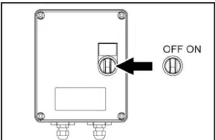
2. BkIOuHTb 6nOK WR, yCTaHOBtB bIKIOUATEJIb B noIooKeHme ON
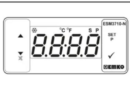
3.YCTAHOBITb TEmnepatyTu CnOMOBIO SET N KHOHOK AV N IODTBePHTb HAgatmEHaV (DnAHAOHN HACTPOIN85-105°C).
4. 10Borpyb 3aMKobb BYkKnIOuATenb BnPaBO do 3aNcyka DBNrATena.
5. Pa36IoknpoBaT BbICOKHaOpHbI NCTOJIET, CDbHyB PpeOxApaHTeBbIΦHKcTop Ha3aI.
6. OTkpbIb BbICOKOHAnOpHbINnCTOnET.
PpumueaHue
3mo 3aumem okono 2-4 MuHym, noka He 6ydem docmuhyma pa6oay mmeIepamypa.
7. IpoBecTuYHnTuToXeHne copHrKOB.
Pexm c npoo6pa3OBaHneM (OuNTka
napomn De3nHfekun)
TonbKO HDS 13/20, HDS 17/20 (onu:
PumeyaHue
Дярабомы e ржиме napooбразови обаменьно нач ue MOHmaхhoо кOMNн ekma dр peунларpoуку усва obopomoe (onuue, c aeeod): 2.013-086.7, komnnek doochacmku: 2.013-014.0)!
△ONACHOCTb
Onachocmb oxoae!
NoBbueHHe paOoee daeneHue u3-3a bICOKou paOoei memepampybl.
Ogbauaeme hHMaHue ha mo, ymo npu paOoe HmempepaYme 105°C paOoe daBneHue HeDoxKn rpeBbMb3 2 MfA (32 6ap).
PnmuemueaHue
Ppu oucme napom pa6oma c 2 cmpyubIMu mpykamu Heo03MOxHa.
- ONUCTKa napom: yctahOBINTB COOTBEETCYBOUee napoBoe cOnno Ha CTpyHyIO Tpy6Ky (HOMep Detannm CBTexHHNECKHX XapaKTpeNtKkA).
2.Дe3nHfeku:уctahOBtB WR 10,20,50 nnn 100 Ha cTpyHny Tpy6ky N BCTaBHTb COOTBeTcByOuoe napoBoe conNo (HomepTean n CM. BTexHHuecknx xapakTeepNkA).
3.YCTaHOHTb BbIKHIOHaTeINb YcTPOIHCTBa Ha peKIM pa60tby(PekmCnapo6pa3OBAHnEM)
4.BKIOHHTb6NOKWR,yCTaHOBHTb BbIKIOUATEIbBNONOXHENE - YctaHOBnTb TemnepaTy p c nomoubIb SET n KHOON A N NOITBpeINb HAXATHEM HA (peKOMeHJyEmbl dHaNa3OH HAcTpOKn 120- 155°C).
- NOBEPHyb 3aMKOBbY BbIKNoyatEnb Bnpabo DO 3anycka DnRrataTeia.
-
OTKbblK KANOT NOBepHyTB MAXOBIK nepenyckHoro KNanana hpoTnB aacobO CTpeKn, 406bl yctAHOBHT MaHOmeTp Ha 30 6ap.
8.Pa3bIokpoBaTb BcKoHAnOpHbI nCTOJIeT, CdBHyB npdeoxpAHnteHbI hKCaTOP Ha3aD. -
OKpbItb BbICOKOHaNoPbHn NCToTeT.
PpumeyaHue
3mo 3aumem okono 2-4 MuHym, noka He 6ydem docmuhyma pa6oay memnepamypa.
10. PnOBeCTN OuCTKny napOM NIN De3HnFcEKnIOF ΦHKnCb Beo3AnachOnTc
1 KOnTpOlbHaJa lamNoKhA 6NkOA WR CBeTuTcR KpaCHbIM: CmUKOM BlcOKOe DaBHeHNE B CnCTEme, ropeIKA OKTKHOaTeC, CM. rNaby (PmouB npn HeNCnpabHOCTx).
2 Ha dinncnne naneHHy npabnene HOBnRETCB ERROR 5: cnHxKOM HN3KOE daBHeMBE CNTCTEM, ropelka He 3nyckaTcR, CM. (PomOuB npn HeNCnpabHOctTx/ERROR 5).
IpepbBaHne pa6oTbI
1.3akpbbBbICOKOHAnOpHbINnCTOJET
2.3a6JIOKIpOBaTb BbICOKOHAnOpHbI NCTOJIeT,
CDBNHyB PnpoOxpaHNTeHbHbIΦnKcTOp BnpeE. PpumeaHue
Koada bblcokohanopHbI nucmonem biknouen,
deuamenI npodkaem paobamHa xonocmm
xody.Boda npodkaem ucpkynupoeamb Meky
bakom c nonnaBKM U HACOC bblcOKO zo daeneHua
noozepaemc. Ppu docmukehuu maKcumaJIbHO
donyummu memnpamby (55 ^ C) dAmuk
memnpamby Ha exode omknouaem deuamen.
Piocse oxnaxdeHua do memnpamby Huke 50 C
paBOMy ycmpoucmea MoKHO 8036Hoomb.
Pocne 3KcnJyaTaun C MOIOUHm CpeDCTBOM
ToJIbKO HDS 13/20, HDS 17/20:
- UctahOBHT Do3IpyOuIe KIanaH MOUeTeo CpeCTBa Ha 已 _ 0 ^ 出
- POMbIb yCTPOHCTBO He MeHee 1 MNHyTb Ipn OTKpbITOM BICOKOHANOPHOM NCTOJTe.
BbIKIOUeHne yCTpOINCTBa
ONACHOCTb
Onachocmbu-3a 0opuey eobbu unnpapa Onachocmb6eapuaehua
Nocne 3Kcnnyamauuu c oopueo bdoou un npam ycmpoucmoe e uenx oxnakdehur dojxho npabomamb npu omkpblomm nucmoneme e meeyehue He meee 2 Muhym c npumehueem xonodohou bdo. BHIMAHVE
Onachocmb noepexdehura!
Onachocmb noepekdeHua
Hukoada He biknouaume deuaamene npu nonho Haepyke c omKpbimbEbcOkoHaOpbIM nucmonemom.
1.YctaHOBnBbBkyIOHHTyCytpOCTBA B noJoxeHeN 0 / 0 (ropeNkBbIK).
2. 3akpbTb nctonet-pacnbintenb
BnuratIb nepexoHT Ha xonocToxOJ.
3. NOBepHyTb 3aMKOBb BByIKIOuATEb B NIOJOKeHne «0»。 KOHTpOJIbHaJaMnOvka "ToTOB K paBoTe" racHeT. YnpabNIOUoee HanpJxKeHne OTKHOuaeTc, M DInCnNeI racHeT.
4. Pn BDOCHa6KeHmOTBHeHHeRoNCTOHNKa: NpeekpbTbNoaayBObl.
- Haxmatab BlycokohanophynnncTOnet, noka daJIeHneB yCTPOJcTBe nonHOCTbO He c6pocntca.
3.a4nKcnpoBt BbCOKOHApnohBn nCTOnet npDoXpaHntBbHmBnKCaTOpOM TnepeHamepeHHOOTKpblr. - PnB OdochabkeHINOT BHeuHero NCTOCHHKAOTcoeHNHTb BOONPBOOBHyI ShaHR OTNCTOHHKA NOaAH NBOby HAMOTaTe EHOha6apabah JnlaShHa.
- Hamotatb BbICOKOHAnOpHbI UHaHr Ha 6apa6aH.
3aunTa oT 3aMep3AHN
ДЯЗАЛТБОТУЕРБА,ПМИНREMOМОР3OM, YCTPOICTBO HeOxOДMо pOMbTb aHTNФPn3OM. ПUMeueHae
NcnoB3o8amcbmaHapmHbIe aIukOeEbe oxnaxdaioue kuoKocmu dna aemomobune.
PpumeyaHue
Cobnodamnbnpdncauhur npou38oumenno obaueHIO c anmufo3OM.
B peyntbale 3 toro taakoe dcctraetcnpedenehna hantnokop03noHHa 3auHtA.
3aunTa DBnraTeJr oT 3aMeP3aHn
- PnOBePntb KOnTp OxLnXeHnI DBrIaTeIHa NaOCTatoCHoCTb AHTNΦpH3a, npI HeO6xoIMoCTn AHTNΦpH3DOnITb.
2.Cm.pa60tI NO TEXHNueCKOMy 06cNyyKBaHnIO «PpOBepKa N OONBAHne OXnAaDHOUeJ KINKOCTN
3aunta akkymyITopo ot 3amep3AHN
- EcnI yCTPOIcTBO B CINbHbM OPO3 He paOtaET HeCKOJIbKO HeJeB, DEMOHITPOBaTb AKyMyJrTOp INoCTaBnTb Ha XpaHeHHe B MeCTO, 3aUuIeHHoe OT MOpO3a.
LcKnuecka npMbIBka aHTnΦpN3OM (Hacoc BbICOKO daBHeH)
1.ПиВОДСАБЖЕнгОТВHEUHERTOCTOCHNKA:OTCOEДИНТВОДПОВОДHBIWIJIAHRTOTNCTOCHNKANoDAUYBOBJI.
2. UctahonBtB bblKnOHTeB yCtPOCTBA B NOXHekne《0/OFF》(ropeNkBaBkn.).
3. C6pocntb daBneHn B yctpoNCTBE.
4.YCTAHOBHTB BILHIOUATEJBY CXTPOJCTBA HA PEXKIM 6a0bToIb 《3auiTTOIOT3AmeP3aJI
5. TOnbkoHDS 13/20,HDS 17/20:YcTaHOBnTbdoIpyouuKnapanMoOJeoCpeCTBaHaMaKcMajbHoE3HaueHne.N3BNeUbBCaCbBaIOUmIuaHrDnmoOJeoCpeCTBaN36aKaIpaMOUeO CpeCTBaNpaMaTeCTBnEroTAK,TO6bOH Mor6bITNoJIHOCTbIO ONOPOXHEN.
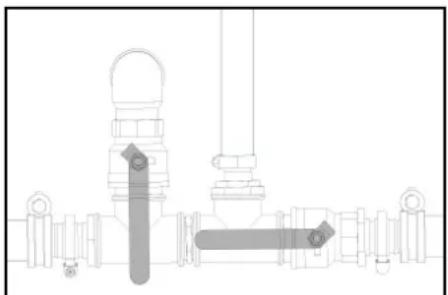
6. OTKpbIbKpAH NOdaH BOdbB 6aK JnA BODbI nCINBHON KpaH, YTObI NOHOCbIO ONOPOKHNTb yCTPOIcTBO.
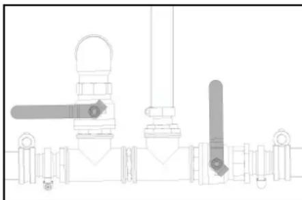
YkaatatebI ypoBnB B 6aKe IaBra NBObl nonHOCTbO onyCKAeTc.
- 3aKpbIb KpaH NoaHn BoIb B 6aK dIa BOIb I 3aKpbIb CnBHOH KpaH.
8.OTcoeMHINb BbICOKHOAPnHbI NCTOJIET OT 1JHaTRA BbICOKORDabBHeHnR.
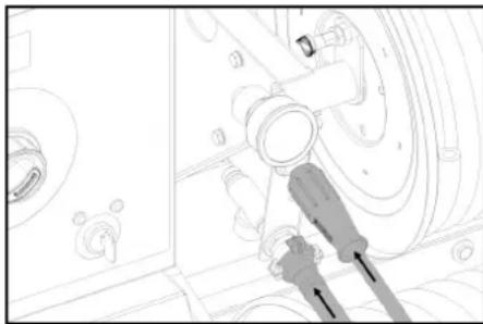
NTOOc0eINHb 5uHrBbICOKoR DAJIeHnK KIOCTOHNK ONaaH aHTNcPm3a.
- NodoeuHunbIy BoDOpnpOboHybI yAnHr IyBOBpTaAHTnΦpH3a.
11.3aHTb aHTnΦpN3 B6ak dЯ aHTnΦpN3a. B6paTb COOTHOJEHNE BOBb/aHTnΦpN3a B COOTBcTbM C DAHHbI pOON3BOJENTeAHTnΦpN3a. - PnoBepNTb KOHcEHTpaUmo aHTNΦpN3a C cNOIb3OBAHmE CTaNdAPThbIX TcTePbOB dIra aHTNΦpN3a H, eCIN Heo6XoDmO, BblONHTb KOPpeKTHpOByK.
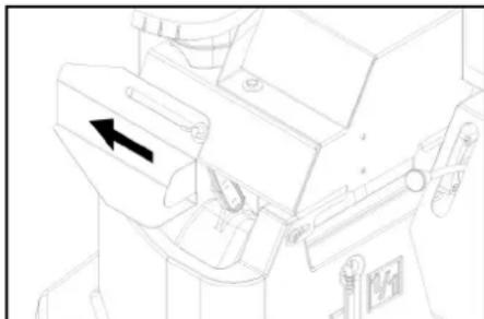
- OtpbIb 3aJIHObE OTBepCTME 6aKa c NONABKOM.ДЯ STOrO ocnaBt 6apaIKOBBI BNT I CdBHyTb KpbUkny BNEBO.
14.3aJIITb 20JIITPOB aHTNΦpI3a B6ak CnonJIaBkOM 3aKpbIb 3aJIINBHOE OTBepCTne.
15.YcTaHOBnTBpbHurynpaBneHHaPoBOrO KpaHa DnAHTNcPn3aBBePTKaNbHoeNOJIOKeHHe.
16.YaHOBINb pbHar shapOBoro kpaHa dnnpeKeKJIOUeHObpAtoHO nToKa npAanIeNbHoHanpaBHeHIO dBXKeHn (20). - Tonbko npx xnoJOnHOM DnBiratene: NobepHyt b 3AMKObbl BkIIOUcTaeB b NONOKeHHe npEbpnteBHO rnporpeBa DnBirateneB NBeBO uyepeKIMBaT b ERO B TAKOM NONOKeHm Do Tex nop, NOka He NoracHEKTOpNbHaN NaMNoQKa nporpeBa.
10.NobephytB 3aMKbBbIKIOyATEb B NOJOKHeH E
POTIK KOHTPOBHAH NAMNOUCA
《3KCNyATAUHOHAR rotOBHOCb》. BKNIOAeTcR
ynpaBnIOOe HANpXKeHne, H Na DmCnPeE
OtobpaAeTc pa6Ooey coCToHne 《3aUNTaOT 3AMEP3AHNRA
19.ПовернгьзамковывькючateьВпраьdo 3аусядагатетя.
ANTnppn3 no kpyry kaaeTcyepe3 ycTpoICTBO
20.CntbocTaKBOBbI,HCnOJIb3yJWNaHrDnAHTNΦpI3a,B6akDNAnAHTNΦpI3a.
21. Nocne cnmba anhnpn3a chepe 7naHr dnn aHTnbpn3a ycTaHOBnTb pnyarynpaBHeHHa SAPoBBM kNaanAHOM nIa hAnPn3Ba bBePTNKaJIbHoE noJoxKeHne I noDooJaTb 5 cekyHd.
22. BbIKIOUHTe DBNrAteJIb.
23. YctaHOBnltb BlykHouateIy cTpoCTBA bNoJoxHee 0 / OFF (ropeNkaBlyKn).
OTkaunBaHne aHTnФpMa3 n3 CmTeMbI BbICOKoRdAaJIeHHa
PumeyaHue
Ipeepeknnyamaueu kyho omkaamb ahmu p3 u3 cucmembl bicokozoa daeneHua opamno e bak dna anmuppzta
- UctaHOBINb pBnarY npAbnEHHaIpaOBOrO kPanaI dNAnTHpN3Ba B VertiKaHbHOe NOJIOKeHJe.
- POnCoeDInHnTb ⅢaHr BbICOKOr DaBJIeHnK NCTOCHNky nOaCh aHTINp3a.
- POnCoeDnHmTb BOOnpOBoHDhI WnAHR dNRA Bo3Bpata aHTnΦpM3a.
- OTKpbIb 3aJIbHoe OTBepCTHe 6ka C nonlaBKMOM.ДЯЗTORO Ocna6bIb 6apaXkoBb BnHT n CdBHyTb KpbUHK BNEBO.
5aNITb20JNTPOB YCHOTOBBoB B6akC NOJIABKOM 3aKpBtB 3aJIINBHOE OTBRECPHE.
6.YCTAHOBINTB BIKHIOATeINb yCTPOINCTBA HA peKIM pa60tIb(3aunTAOT3amep3AHNIA
7. TOnbKO npxXoJOnHOM DBuratene:
NOBepHyTb 3aMKoBb BblKIOuOaTeNb B NOIOKeHne npedBaIHTbHorO NpORpeBa DnRatEnr BNEBO yDepKNaTbeeroB TakOM NoIOKeHm Do Tex nop, NOKa He NorachET KOHTpoNbHa RaMNoOyKa nporpeba.
- NObepHyb 3aMKOBbl BbIKIOHaTeB bNNOKeHHe «I」。TOPIN KOHTPobhna lamnOuKa «3KnCnPytaauHOHHa roTOBHOctb」 BKNIUoAeTcR ynpabnlouee HaprJKeHHe, n Ha NcInee OTo6pKaaeTc pa6ooee coCToHHe «3aunTa oT aMepe3AnHn
-
NobePHTb 3aMokBoB bblKlHouateIbnBpAzo DO 3aynCaZ bDInatraIena.
ANTnΦpN3 BmecTe C uHCTO BDOI NOCTyNAET 36aKa C nonJaBkOM B 6ak DnA aHTnΦpN3a. -
BánqinHàntbI pOmbSbIKB Y TcEHMe INp6N.2 MInHyT, NOKa HE ZANHONHTC 6aK DnA HtNTDpHa3.
-
BbIKIOHnTe DnBnTaTeNb
- YctahOBnTB bBkNIOuATEb yCtpoCTBa B noIOXKeHne «O/OFF» (ropeIka BbIKn.).
TpaHcnpOpBka
OCTOPOXHO
OranochmbolnyuHmtpaum u noepexdehuif Hnehdnaeua mpaHcnnpmoeka
Yumbleambeecympocmea npu mpanchopnpmopeke.
BHIMAHHE
Onachocmb nopekdehur!
Henaonekaa mpaHcnopmuo6ka
Bo epemmpaHcpmupoeku obecneumb 3auumy
cnyckoeo20 pyuza oom nopekdeHua.
Pexm DnHexeHnC npuenom
PnMueaHHe:BodTeB, KOTOpb ynpaBnIe TpAHCNOPTHbIM CpeCTBOM C pRtneom npn DnKHeHN NO doporam OoBero nOIOB0BaHN, DOJKeH NMeTb COOTBeCTByUooee pa3peSeHHe (BODTeBckne npba COOTBeCTByOooie kateropnn).
ONACHOCTb
HenpeeduodeHHbI xapaKmep duxkeHua
Ipu yacmuHNo 3aonHHeHHom 6bake dna eodbl 083MOxHO packaueaHue unu onpokubbaHue ycmuocme a cnayae pe3ko2o noeopoma unu pe3ko2o mOpMoxEHua.
Ipeod hauanom deuxeHnO npoxHmB bak dnoEoBb Hnn HanoHmB e0 do MaKcMaJIbHo2o ypO8H.
- Ecnn DOnyCTmBm OBnn BEc COCTaBnRE 1600 K, NOHOCTBn3aONHNb INN ONOPOXHNTb BAK DnB BObl. ECnn DOnyCTmBm OBnn BEc COCTaBnRE 1100 K, NOHOCTBn ONOPOXHNTb BAK DnB BObl.
- Ha yctpoiTbax 63 bapa6aHa dna JnlaHra OTOOeHNHTb IuaHR BbICOKoDAbnEHAOTB BbICOKHOANOPHO BbXoHaN NOONKTb HA xpaHeHBe B COOTBE TcByIOUIN OTcEK YCTpo
- OTKMHytb nepehdn 3aunThb oBecn (onu)BVEpeD, 3aFmKcPOBaBt.
4.CTHyTBBHN36pe3eHTOBOE NOKpbITHe 3aDHeuactn (ONU) H3aФNKcPObaTb. -
OtperynnpoBbY BlicOTy TROBOrO DbluNc N NOMOuIbY npHOrO KOneCa No Blicote CuENHOYCTPOINCTBa TtRuaA.
-
YCTAHOBNTB CTpaxOBOUHbI TPOC HA TARaY.
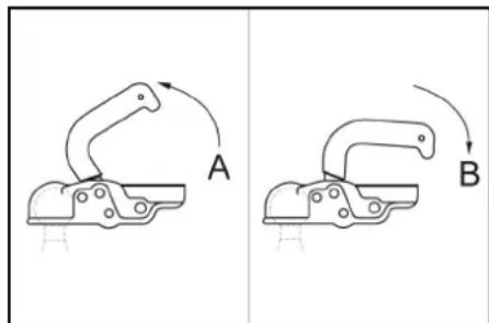
① CuenHoe yctpoiCTBO OTKpIto
② Cuenhoe yctpoiCTBO 3akbyTO
- NotaryTb pbIyar cIeJIeHnB BBepx (OTKpbITb).
- YCTAHOBINb TAYBOE DblIHO HA WAp CcENHORO yCTPOHCTBa.
- Haxatb pbuHar cuENHeHHaBn3 (3akpTb) npeBecTe Iero BNOJIOKeHHe, npaPnJIbHoE TRBOOMy dlIHy.
10.YCTAHOBINTIb TEKEPHOE COEINHEHNE 3NEMeHTOB OCBEUHNE TpaHCnOPTHORO CpeCDTB.
11.Повернъ уpophoe konecoc nOMOUsbHy pyKoTkn BBepx.
12.CIeHb3aTeM,HTObblOnOpHoeKoNEcBO BTAHyTOM NOnOxEHmYka3bBAnBn HAnpAbHeHm npuena.
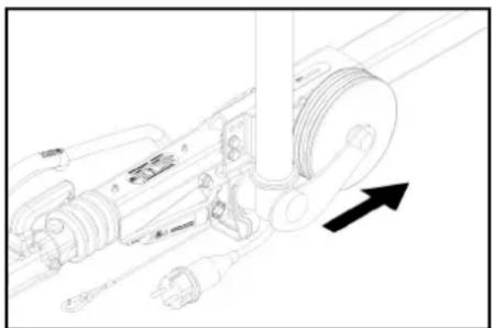
-
6UpaBt npOtoOBKATbHe ynpobI ni-IOK cneN bCTABnB b KpENJIeHa.
-
OTNYCTNTB CTORHOCHBI TOPMO3.
- PpOBepnB TaemEnbOcBeHnnpuena (ΦoHApn CnHnA TOpMOxEHn, yK3aTeEN NOBopoTa, rabapnThbe ΦoHApn, fohApb OCBeHnE HnopeHOro 3Ha) Ha npEomet npaBnBHOrO FyHKUHOHPOBaHnR.
- PnOBePrtb ⅢHbI Ha npEeMTe HAnuHnNoCTOPoHHnx npEeMeTOb, 3aCtprBbXn BnpOTEKeTope.
- PpOBePbTb CoCToRHaHne uHH
- NpOBeRtNb DaJIeNHeMoB3DyXa B WInHAX, CM.
.
PnmeaHne: Co6nIaTb MeCThBle OrpauHcEHnA COKOCTN DnKHeHnI DnT PAnCnOpTbIX cpeCTB C npueHON.
TpaHcnopTnpOBka KpaHOM
ONACHOCTb
Hehadnexkaa mpaHcnopmupoeKa kpaHOM
Onachocmbmpaemupoeanura nadaouum
ycmpoucmeom unu nadaiozmu npedMemamu
Cobniodamb MecmHbIe npaeuna mexHuKU
B30nachocmu yka3aHua no mexHuke
6e3onacchocmu.
TpaHcnnpuOeKa ycmpoucmea KpaHOM oJnxHa bInIOJIbMb cIIObKO IuaMu, OByeHNbIMU ynpaNEHOKpaHOM.
Ipeo Kaokou mpaHcnpmuOeKoKaPAHO
npoeepbmyepnoonobemhoeycmpoucmeho npedm meopexdehu
IpeepKaKooIpaHcnOpmpuOeK kPcHOM npoeepmbpykyhApneMoepeXedhu
IodHumamb ycmpoucmeo monbko 3a pyky.
Heucnonb30eambenHbcecmponb
Фкс cupoeambn noьemhoe ycmpoicmeo om HnpehamepeHHO2O mcoeduneHua epya3a.
Pepo mpaHcnpmOpou KpaHOM cHMybcmpuyHyOmp6ky C bCkoKHOANOpHbIM nuCmOnemOM, connAmu, ouCummuem NoepexHoCMU uDpyzUMHe3akpenHeHHbIM npdeMamu.
B O epem npoecca nodbema He mpaHcnpmupoeamb Ha ycmpoocme Hukakux npedmemoe. He cmoar nob ayzom.
Ppu 3mom cneedumb 3a mem, ymoobie onachou 3ohe kpana He haxodunucb nOu.
He oceanbmycmpouicmeo nooeeuHm K kpaHy 63 npucmora.
XpaheHne
OCTOPOXHO
OnachocmbmpaMupoeanu u nopejdeHn npu heco6nodenu eeca!
Ppu mpaHcnnpmUoe u xpaHenu ycmpoucmea cyueeymem onacohmb pmaMupoeanu u nopejdehna 13-3a e0eeca.
Ppu mpaehnpmupoeke u xpahehu yumtbieaume eec ycmpoue mea, cmaay TexHuueckue xpakmepcmuu.
BHIMAHHE
Onachocmb nopekdeHua eo epMa Mop03a!
He nonHocmbio cIumar oOa moKem noepedumb
ycmpoucmoo npuHadnHexKocmu npu 3aMep3aHu.
Tinnochmsn cteume oody u3 ycmpoucmeu u npnaednxkocmeu.
3auiuuaume ycmpoucmeo u npuhadnejxocmu om MOp03a.
YXOD IN TexHnueeCKoe 06cnyxHBaHne

① 3aMbHoe OTBepCTne INI MToPHoro Macna (cbepxy)
② 3aɪnBHOe OTBepCTne IŋI MToPHorO MaCna (c60ky)
3 IImepeTbHbI yypOBBMaCna(DnRatB)
4 MacnHbI pInbTp (DnuratneB)
5 Pe36b08a npo6ka macnocnBHO OTBepCTNA DBHrataTEn
6BdooOtDenHntelb
7ToNNMBHbIΦnBtP
3aHnBHOeOTBepCTneTpaHCMCCMOHHORo MacnaDnI nepeaHc BbIyckOM Bo3dyxa
9 Pe36bO8a npo6ka macnoocnBHOrO OTBepCTna npomexkyTOHOro peyKTopa
10 MacnoMeHoe cTeKnIO npomExyToHoro peDyKTopa
11PpokKa MacnocnHoro OTBepCTna, Hacoc
12 CMtpoBoe CTeKNo Hacoca
13 13MepnTeBHyIuynypOBHMaCna(HaCoC)
(14) PpdoxpaHnteHbHbI bNoK ropEnKu
15 Klaanan dny cna aHTnФpna3a
(16)MaHOMeTpNueckn BbIKJIouaTeNb
(17)IpenyckHKnanaH
18 BxOJ MOUoIe O cpeDCTBa
19ФильтпpresdВapTteBHOOчNTKNHacoca
20KohtpoJIbHaN 1
②TOIINBnHbIΦnIbTp
② Ctaprep
20CBeTnTeNbHreHepaTop
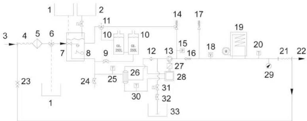
TexHONORnuecka cxema
① BaKДЯANTnФрИЗА
② EMKOCbIyIyIyIyIyIyIyIyIyIyIyIyIyIyIyIyIyIy
③ПодачБОдь
4Bapaban nnaHra Hn3KOr daBneHn
⑤ BóyaHòu φnMbTp Ha BxOe
6) Wapobon kpan cnCTembl 3aunntb OT 3aMep3AHNA
7 BaK c nonJaBkOM
⑧ 3aunTaOT HeoctTaKbOBoBbl
BnyckhoKpaH6kaDnBdoB
10 BaKДЯ BODJI
11単ロ�岡KpaHДЯnepeKIOUeHnOOBpaTHoro noToKa
(2)ΦnIbTp npEaBapTeNbHO OHCTKHaCoc
13HacocBbICOKO TaBJIeHHa
(4)NepenynckHou Knaan
(15)MaHOMEtprueckn BbIKIouaTeNb
16O6paTbHKnIaHaN
(17)PpeoXpaHnTeIbHbI KNaanAH
(18)Pene noToka
19PpOToHbIHarpeBaTeB
20 DaTnK TemnepaTpyb RopEnk
21Bapaan DnnaaHaRa BbICOKo DaBneHn
22BbIXoD BbICOKOrDaBnHeHH
23 ObaTHbI NOTOK aHTnΦpns3a
(24)CnBHOH KpaH
25 DaTnK TempepaTypb BOBb Ha BXOe.
26TeNnOo6MeHHNK
(27)PomexyToHbI peyKTop
28)ДиЗ entbHДВИrataTeB
(29)MaHOMeTp
30 DaTnK TeMnepaTpby OXnaXdaIOe BODbl
313NeKtPOMaHHTbHKnAnaH CnCTeMbNoaW MOHOJIero CpeCTBa
32 D03npyuounn KJnaHMOOeRcpeCTBa
33 BaK DnM OIOUero CpeDCTBa
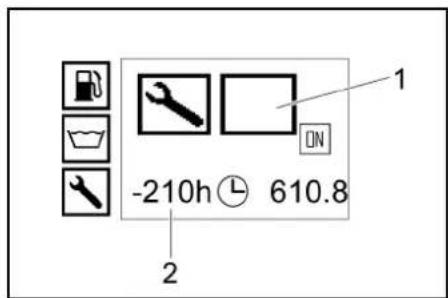
Dncnne cepBnCHOn cnyK6bl
| СИМВОЛ | Вид paбов сөрөнөнөлүхь |
| Сөрөнөнөе оБспүхиВанөе рорөн | |
| Сөрөнөнөе оБспүхиВанөе дыralтел | |
| Сөрөнөнөе oБспүхиВанөе hacocа | |
| Сөрөнөнөе oБспүхиВанөе БыICOKHAnOPHOrO ПICTOLeTa |
PepnoDnHocTbTexHueckoro 6cJyXnBaHH
Pa6oTbI NO TexHnueckomy 06cnyKuBaHHIO △ONACHOCTb
PepoepeHm p6bX pa6om Ha ycmpoucmee ebKIOUymb 3aMKo6bI ebKIOUamEnb U u3AneB KIOU.
ONACHOCTb
Onachocmbmpaemupoeahue cneedmeue ydapa 3nekmpuueckum mokom
He Knaemb Memannueckne npedmembHa Zenehepamop unu cmapmep.
△ONACHOCTb
Onachocmb 83pbbea!
OnacocmbmpaemupoeaHua u noepexdeHua He knaemb unchpmyehmbu unu noo0bhe npedembl ha akkymymop, mo ecmb ha noiohcbbe bbaobu mekxneMeHHbte nepeMbHKU.
He donyckamb kypeHu r omKpbim02 oHa.
Bo epma 3apdka kkymynnapoe b nomeeHua x oecneumb docmamoyhyo ehmuniauio.
Vcnpb3oea mbo kpa zpeueHbte KOMHaue H Karcher akymnmoIby aepaHbye ycmpoUmea (opueunabHe bte zanaChy qucm).
- DAtb yCTpoIcTBy OCTbITb.
OuHcTKa BOJrHOro QnIbTpHa HxOe
1.CHrBBoJHOHΦnIbTpHaBXOeNIMBNEy naTPOHΦnIbTpA.
2. OCHNTb NAHOTPOH NHTBpa HCTOBNBOOHNJNCKATbIMB BOADYXOM
3. Choba co6paB B o6paTHoN oCneObaTeNbHOCTn.
OuNTKa pfHbTpapneBapnteHbHO OuCTKn Hacoca
1.C6pocntb daBneHn B yctpoiCTBE.
2. CHaTbФnIbTp npEpaBapTeIbHOH OuNCTKn HAcocan N3BNeHb NaTPOHФnIbTpA.
3. OuHCTnTb nATPOH qHnBTPa YnCTOJ BOoI INCKaTbIM BO3DyXOM.
4. CHOBA co6paTb B 06paTHoN nocneDobATEIbHOCTn.
OuNTKaФnIbTpBaBOBcAbHoueM WJHaHRe DnmoIOUeO CpeDCTBa
- Otpytnb pe3b6oByk KpbuKv BcabBaioe oIaHa rna moouero cpeCTBa.
2.BbTMyb BcAcBbAIOuMn 7nAHr DnMaMOoero cpeCDTa. - NombTb pInbTp B OBe n yctAHOBnTB Ha MeCTO.
PpOBepka yPOBnMa MCnBa DnBnraTepe N DOJIbMOTOPHOrO MaCnA
PpumeyaHue
3anpaochyb oobem Meyoyommemkamu MIN u MAX Haumepumehnouyne cocmaenreem 1,6 n.
1. N3BneuN3MePnteHbHbI uyn, npoTepeTb n CHOBA BCTaBNTb.
2.Eue pa3 nABnueb yyn n npOBepntb ypOeHb Macna. YpOeHb Macna BnpAke,ecn OH HaxoNTcB npedanx OTMeTKn Ha yyne.
3. Ecnim ypoBeHb MaCna HaxoDInTc HIXKe OTMeTKHa LyNe, OTKpBcKpKbIyHrAJIINBHOrOTBepCTnI HAnITb CBexTeO MOTOPHOroMaCna.
4. NooxdaTb NtB MmHT, NOKa MOTOPHOe MacNo He coBepeTcB MaCnHOH BaHe.
5. PpOBepuB typoBeHb Macna, KaK OnncaHo Bblwe.
- Pn Heo6xOdMocNt npoecc NOBtOpTb To Tex nop, noka yopoeHb MaCn He 6ydt HaxoDutcb B nepeDenax OTMEKHa LcNy
- Nocne npoeBkCTABNTbIy nI 3akpItb KpbIky 3aJIbHOrO OTBePCTyA.
PpumeyaHue
7y3bipbku 03dyxa donkhbiebmu.
Mapka macna yka3aHa e 2nae «TexHuueckue xapakmepucmuu
IpoBepka ypOBH MaCnBa B npomexyTOuHOM peyKTope nOJINBAHne TpaHCmCCHOHHORMaCna
- IpoBepntb ypoBeHb Macna Ha cMOtPOBOM cTeKJI npomexkyTOHOro peykTopa.
YpOBeHbMaCnIpaBnIbHbI,ecNHOH HaxoIITcno CEHTpy CMTOPOBOrO CTekna. - Ecn ypoBb MaCna HnKecepeDnHb CMOTpOBOrO CTKNa, OKnPbTb KpbIky 3aJIbHOrO TOBepCTN I 3aJIbTb CBeKee TpaCMNCIOHOHoe MAcNo.
- 3aKpbTb 3aJIIMBHOe OTBepCTne
PpumeyaHue
Ny3bipbkue 03dyxa donxHbI ebiumu.
Mapka macna yka33a ha 2 anahe "Texhueckue xapakmepucmku"
PpOBePKa yPoBnMa n3MePntIbHbIM uynom Hacoca BbICOKoRaDaBHeHn I DOINBaHne Macna
- BbBNTMb N3MepntbHbI uyn, npoTepeTb n CHOBA BCTABNTb.
2.EepeaBbHHTbN3MpTeIbHbIyynnpOBepTu yPOBeHbMaJa.
UpyoBbMaN paRnblbHb,ecNJ OH HAXODITcB BnpDeaX OTMeKn HA sNyue.
- Ecyn ypoBeH MaCna HaxoNTcH HnKe OTeMkN Ha UyIe, HAnITb CBExero MacJa.
4.BBnHTntb n3MePnteIbHbIyUyn.
IpumeaHue
Ny3bipyku 803dyxa donxKhbl ynemyuumcbra.
Mapka Macna yka3aHa e 2nae «TexHuYeCKue xapakmepucmuu».
IpoBepntb oxJaDaIOOyU XnKIOcTb IdoNTb.
OCTOPOXHO
Moaym 06pa3o8bIeambc epehblie eueecmaa.
Obaauiue bHuaHue Ha Mapky uonb3yEmo2 aHmuPua3a.
Cmeuueaue Hue moxem 6bl3amb xumueeckyio peakuo. He cmeuuaue pa3Hbme Mapku anmupepu3a.
△NPEaynPExdHne
Onachocmb nepepeea deuaamena
Ieuaambe 63 oxiaokaoouei xukocmu moem nepepsencb.
HemeDneHNO ebiknIOUmb dbuaamnb u dam emy ocmblb.
△PENDYNPEXDEHNE
Onachocmb nepepeea deuaamena
Ieuaambe 63 oxiaokaoueu xukocmu moem nepeapemcb.
EcnduaemnbnepepecnHaembo,ymo 0bIXoDum oOraHou nap,duaemnbHyxho
HemeHnHO omKIOUHMb U depXaMboc om Heo Ha be3OanachOM paccmouHu, noka He yMeHbumbcB daTeHeu.
BHIMAHNE
Onachocmb 6eabpuaeunn oxankaouoe oodou deuaamena
KOMNHECAUONHHb b4aok Haxodumc noa daeneHuem. 3anpeaaemc okmkbeamb kpbuikya Ha KOMNHECAUONHHo a4ke dno xoaiaadoeu Xudokcmu deuzamena npu pa6ooye memnepamype.
- OtkpbIbKpbIbIKyKOMnEHaCnOHHo6aKaDJaOxJAAQIOeJXKIOCTNDBIATEJIA,DOINbCBKeJeYCHOTOBdIiCOOTBeTCTByHoumAnHTNcPm3DoOTMETkMax.
PpOBepka/ounctKa BO3dyuHoro FnIbTp
PpumeyaHue
Ipy60 ou cquKu o3dyuhoo ounbpa moKno h noCmaaum cbOpnbH KOhneHep no rampy6ok dn Cnua oakDa u Haukam ha nampy6ok.
PpumeyaHue
Cunbno 3aaraenHHeBtu Unu HeucnpaBhe naPonHbI duNmuHa NHyKHO 6oHouM.
1.OcnaBnTpnyKHHNYO3aXmMHYIOCKOy,CHRTb KpbluHKUyADNJLNTOJKeHBNIy
2. CHaTbΦnIbTpYIOUIN 3JEMENT.
3. IpoDyTB naTPOH nIHTpyCNCKaTbIM BO3dYXOM (MaKc. 26ap).
4. OuHCTnB KOpTc BO3DyUHOrO FInbTp aN3Hytpn caΦeTkoI.
5.BCTaBnTb naTPOH B KOpnyC Bo3dyuHoro FInIbTpa.
8.YctahOBHTb KpIbIKy 3aKapenITb e npYkHHOH 3akHMHc KcO60JI.
PpOBepKa KInHOBOrO peMH BcHTnIaTopa
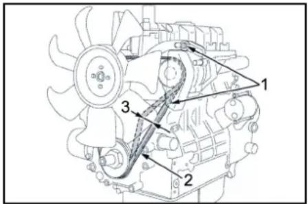
① KpeneXHbIe BnHTbI reHepaTopa
2KINHOBOpeMehb
③ HatakeHnepeemn7-9MM
IpumueaHue
Ecni KluhoBpemHeh HedocmAmoHn HamrHym, Moem npousou mpepees deaamenu unkyMnyamop He noNocmbzapdumc.
- OCTaHOBtB DmRatEnb H N3BNeYb KIOH N3 3AMKOBOrO BblKnIOuTeJIa
2.Дпя npOBePRn HATЯЖeHrN pEmHry BdABtB erO mExypeMeHHbIMn WkMbAMn BoJbWMn NaJIbCem.
PpumueaHue
Klnuoboe pemeHb doJxhen npodaenueaMbsra np6bn. ha 7-9 MM.
PpumeyaHue
3aMeHumb noepexkdeHHbIe KNUHOoepeMHU.
Cma3Ka TopMo3a HaKaTa
1.CnmooBbOCTaHdapTHORcMO30HOrOunpMa 3anpeccOBaTcBOETcTBYIOU KOHCNCeHTHYO CM3ky HAOBNXcMO30HyHXHHINIENX.
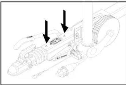
(1)CMa3OuHbI HINIIeJIb
PpOBepKa DaBHeHnBa Bo3dyXa B uHax
- NocTABnTB yCTPOBCTBO HA POBHO NOBEPXHOCTN.
2.ПодсоeMHtBКBEHTNIOUHbMaHOMeTpДЯ npOBePknDabIeHnBO3dYxaBuHax. - Поберпьдадингшоахуma(СМ.«ТexнческinesxapakTepnCTKIN»)И рпн Heo6xOДMOCHTOPERYNIPOBATb.
3aMeHa Koneca
ONACHOCTb
Onachocmb dna kua3hu npu HenpepbieHOM
dopoxhOM duxxehu
Ipnapkyume ycmpoicmeo ha poehou noepexhocmu Hadehme ceemooppaxuyo odexy npu ebnonHeuu pemOnhBx pa6om Ha dopozax obuezo nonls30aHua.
1.Пиразковать усточь на ровhorn noophobiaхочи。()
2.Поверпьтбафьнбосту ргтуна.ЗakpenNTb yctpoiCTBOOTHENPON3BOIbHOroHaNaHa DAIBXKHeN,NOДLOJNXB NOД Hero KINH.
3. 3aФИКСИРОВАТБ CTORHOUHbI TOpM03.
4. PpOBepntb HnHbI.
5. PnoBepnIt bIHHbI Ha npEeMTe HauHmYIa NoctOpOHnHx npEeMeTob, 3actPraBux X BnpoteKtope.
6. ydaHnTb nocToPOHHne npedMeTbI.
7. NcOnb3OBaTbNOxOJIaee CTaHApTHOE cpeCTBOI pENMOHTaIIHH
PpumueaHue
Cobnodmb pekomehdaa ucoomeemcmeyouezo npou3oedumeta. TaIbHeuue 8dukeHue 03moxho C cobiodehmuem yka3ahun npou3oedumeta. Ppu nepeoi ke 03moxhocmu npou3eecmu 3ameHy uhu bI unu koneca.
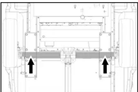
- YcTaHOBnTb abTOMoBnIbHbI dOmKpaT B
COOTBETCTBYIOUeONOPHOI TOUKE.
9.Ocna6ntb konechble 6oNTbl.
10.Пиногнгь устpoичб cnomoьюдмкраТa. - BbBepHyb KOeChbIe 6oNTbl.
- CHaTb KOneCo.
13.ПпставитьзанhoeКолесо. - BctabBe konechBle 6ontbl
- OnyCTb yCTpoCTBO C NOMOJIbIO DomKpaTa.
16.3aTMyb KOJIeCHbIe 60NTbl KpeCT-HaKpeCT.
MOMENT3ATRAKKI
110-120HM
PpumueaHue
DomKpam He exoum e oBem nocmaeku.
PumeyaHue
NcnoB3oeamb nodxodauu cmanoapmnb doomkpa
Pnpuen
- Perynaphno npoBepaTb TOpMO3HyO CNTeMMy Iwaccn Ha oOpNuaJIbHOI CTAnuIN Texo6CnyKBAHnA.
POMOUsb npn HEnCnpaBHOCTx
ONACHOCTb
HenpeHamepeHHbI 3anyck ycmpoucmea
OnachocmbmpaemupoeaHua,yad 3neKmpueckum mokom
Npeo npoebeHem nio6bix pabom Ha ycmpoicmee ycmohounb 3amKOBb bblKnioquamenb e noNoKeHue 己 u 1ueney knoi.
ONACHOCTb
HenpehamepeHHb3anyckycmpoucmea, kacahue mokoeedyux yacmeu
Onachocmbmpaemupo8aHua,yap 3neKmpuueckum mOKOM
Ipeo npoebeHem paom Ha ycmpoucmee bkioumbycmpocmeo.
U3ene4wmcencbHytoeunky.
ONACHOCTb
OnaHocmb 63p8la u KopoMko 0zAmbKaHua. He KNaCmB uHcmpyMeHbI uU nOo6hBe npdeMeMbHa aKKymyTnOp.
1 DaTb yCTPOINCTBY OCTbITb.
OTo6paKeHHe HeMcnpaBHocTH
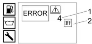
①Homep HEnCnpaBHOCTN
② DnBaTaeBbIKIOeH(OFF)
CepBnchna cnx6a
ECINHcnpaHObct He ydaetcYcTpaHntb,ycTpoIcTbO Heo6xOIMO OtnpabnB Ha npOBepky BcePbcHyO cny6y
HencnpabHocTn c Hdkauee Ha dncnnee
| Ошиба | Почина | Устрахени | Оъевственoe мларо |
| ERROR 1 3ардн的眼ok | Натяжени Клиноюгор ремь на вентлартоpe симлakом салбоe. | 1. Побтугуны Клиноюгор ремь вentлартора. | О�еротop |
| Генератор Нет салпавен. | 1. Ровериту 힍ератор, по необхостам замени. | Сервсяная сухкba | |
| Устристwo контrolа залддддддддддддддддддддддддддддддддддддддддддддддддддддддддддддддддддддддддддддддддддддддддддддддддддддdддддддддддддддддддддддддддддддддддддддддддддддддддддддддддддддддддддддддддддддддддддддддддддддддддд徳с. | 1. Повероту Саллартора. 2. Дату Саллартора. 3. Дату Саллартора. 4. Дату Саллартора. 5. Дату Саллартора. 6. Дату Саллартора. 7. Дату Саллартора. 8. Дату Саллартора. 9. Дату Саллартора. 10. Дату Саллартора. 11. Дату Саллартора. 12. Дату Саллартора. 13. Дату Саллартора. 14. Дату Саллартора. 15. Дату Саллартора. 16. Дату Саллартора. 17. Дату Саллартора. 18. Дату Саллартора. 19. Дату Саллартора. 20. Дату Саллартора. 21. Дату Саллартора. 22. Дату Саллартора. 23. Дату Саллартора. 24. Дату Саллартора. 25. Дату Саллартора. 26. Дату Саллартора. 27. Дату Саллартора. 28. Дату Саллартора. 29. Дату Саллартора. 30. Дату Саллартора. 31. Дату Саллартора. 32. Дату Саллартора. 33. Дату Саллартора. 34. Дату Саллартора. 35. Дату Саллартора. 36. Дату Саллартора. 37. Дату Саллартора. 38. Дату Саллар/toр. 39. Дату Саллар/toр. 40. Дату Саллар/toр. 41. Дату Саллар/toр. 42. Дату Саллар/toр. 43. Дату Саллар/toр. 44. Дату Саллар/toр. 45. Дату Саллар/toр. 46. Дату Саллар/toр. 47. Дату Саллар/toр. 48. Дату Саллар/toр. 49. Дату Саллар/toр. 50. Дату Саллар/toр. 51. Дату Саллар/toр. 52. Дату Саллар/toр. 53. Дату Саллар/toр. 54. Дату Саллар/toр. 55. Дату Саллар/toр. 56. Дату Саллар/toр. 57. Дату Саллар/toр. 58. Дату Саллар/toр. 59. Дату Саллар/toр. 60. Дату Саллар/toр. 61. Дату Саллар/toр. 62. Дату Саллар/toр. 63. Дату Саллар/toр. 64. Дату Саллар/toр. 65. Дату Саллар/toр. 66. Дату Саллар/toр. 67. Дату Саллар/toр. 68. Дату Саллар/toр. 69. Дату Саллар/toр. 70. Дату Саллар/toр. 71. Дату Саллар/toр. 72. Дату Саллар/toр. 73. Дату Саллар/toр. 74. Дату Саллар/toр. 75. Дату Саллар/toр. 76. Дату Саллар/toр. 77. Дату Саллар/toр. 78. Дату Саллар/toр. 79. Дату Саллар/toр. 80. Дату Саллар/toр. 81. Дату Саллар/toр. 82. Дату Саллар/toр. 83. Дату Саллар/toр. 84. Дату Саллар/toр. 85. Дату Саллар/toр. 86. Дату Саллар/toр. 87. Дату Саллар/toр. 88. Дату Саллар/toр. 89. Дату Саллар/toр. 90. Дату Саллар/toр. 91. Дату Саллар/toр. 92. Дату Саллар/toр. 93. Дату Саллар/toр. 94. Дату Саллар/toр. 95. Дату Саллар/toр. 96. Дату Саллар/toр. 97. Дату Саллар/toр. 98. Дату Саллар/toр. 99. Дату Саллар/toр. 100. Дату Саллар/toр. 101. Дату Саллар/toр. 102. Дату Саллар/toр. 103. Дату Саллар/toр. 104. Дату Саллар/toр. 105. Дату Саллар/toр. 106. Дату Саллар/toр. 107. Дату Саллар/toр. 108. Дату Саллар/toр. 109. Дату Саллар/toр. 110. Дату Саллар/toр. 111. Дату Саллар/toр. 112. Дату Саллар/toр. 113. Дату Саллар/toр. 114. Дату Саллар/toр. 115. Дату Саллар/toр. 116. Дату Саллар/toр. 117. Дату Саллар/toр. 118. Дату Саллар/toр. 119. Дату Саллар/toр. 120. Дату Саллар/toр. 121. Дату Саллар/toр. 122. Дату Саллар/toр. 123. Дату Саллар/toр. 124. Дату Саллар/toр. 125. Дату Саллар/toр. 126. Дату Саллар/toр. 127. Дату Саллар/toр. 128. Дату Саллар/toр. 129. Дату Саллар/toр. 130. Дату Саллар/toр. 131. Дату Саллар/toр. 132. Дату Саллар/toр. 133. Дату Саллар/toр. 134. Дату Саллар/toр. 135. Дату Саллар/toр. 136. Дату Саллар/toр. 137. Дату Саллар/toр. 138. Дату Саллар/toр. 139. Дату Саллар/toр. 140. Дату Саллар/toр. 141. Дату Саллар/toр. 142. Дату Саллар/toр. 143. Дату Саллар/toр. 144. Дату Саллар/toр. 145. Дату Саллар/toр. 146. Дату Саллар/toр. 147. Дату Саллар/toр. 148. Дату Саллар/toр. 149. Дату Саллар/toр. 150. Дату Саллар/toр. 151. Дату Саллар/toр. 152. Дату Саллар/toр. 153. Дату Саллар/toр. 154. Дату Саллар/toр. 155. Дату Саллар/toр. 156. Дату Саллар/toр. 157. Дату Саллар/toр. 158. Дату Саллар/toр. 159. Дату Саллар/toр. 160. Дату Саллар/toр. 161. Дату Саллар/toр. 162. Дату Саллар/toр. 163. Дату Саллар/toр. 164. Дату Саллар/toр. 165. Дату Саллар/toр. 166. Дату Саллар/toр. 167. Дату Саллар/toр. 168. Дату Саллар/toр. 169. Дату Саллар/toр. 170. Дату Саллар/toр. 171. Дату Саллар/toр. 172. Дату Саллар/toр. 173. Дату Саллар/toр. 174. Дату Саллар/toр. 175. Дату Саллар/toр. 176. Дату Саллар/toр. 177. Дату Саллар/toр. 178. Дату Саллар/toр. 179. Дату Саллар/toр. 180. Дату Саллар/toр. 181. Дату Саллар/toр. 182. Дату Саллар/toр. 183. Дату Саллар/toр. 184. Дату Саллар/toр. 185. Дату Саллар/toр. 186. Дату Саллар/toр. 187. Дату Саллар/toр. 188. Дату Саллар/toр. 189. Дату Саллар/toр. 190. Дату Саллар/toр. 191. Дату Саллар/toр. 192. Дату Саллар/toр. 193. Дату Саллар/toр. 194. Дату Саллар/toр. 195. Дату Саллар/toр. 196. Дату Саллар/toр. 197. Дату Саллар/toр. 198. Дату Саллар/toр. 199. Дату Саллар/toр. 200. Дату Саллар/toр. 201. Дату Саллар/toр. 202. Дату Саллар/toр. 203. Дату Саллар/toр. 204. Дату Саллар/toр. 205. Дату Саллар/toр. 206. Дату Саллар/toр. 207. Дату Саллар/toр. 208. Дату Саллар/toр. 209. Дату Саллар/toр. 210. Дату Саллар/toр. 211. Дату Саллар/toр. 212. Дату Саллар/toр. 213. Дату Саллар/toр. 214. Дату Саллар/toр. 215. Дату Саллар/toр. 216. Дату Саллар/toр. 217. Дату Саллар/toр. 218. Дату Саллар/toр. 219. Дату Саллар/toр. 220. Дату Саллар/toр. 221. Дату Саллар/toр. 222. Дату Саллар/toр. 223. Дату Саллар/toр. 224. Дату Саллар/toр. 225. Дату Саллар/toр. 226. Дату Саллар/toр. 227. Дату Саллар/toр. 228. Дату Саллар/toр. 229. Дату Саллар/toр. 230. Дату Саллар/toр. 231. Дату Саллар/toр. 232. Дату Саллар/toр. 233. Дату Саллар/toр. 234. Дату Саллар/toр. 235. Дату Саллар/toр. 236. Дату Саллар/toр. 237. Дату Саллар/toр. 238. Дату Саллар/toр. 239. Дату Саллар/toр. 240. Дату Саллар/toр. 241. Дату Саллар/toр. 242. Дату Саллар/toр. 243. Дату Саллар/toр. 244. Дату Саллар/toр. 245. Дату Саллар/toр. 246. Дату Саллар/toр. 247. Дату Саллар/toр. 248. Дату Саллар/toр. 249. Дату Саллар/toр. 250. Дату Саллар/toр. 251. Дату Саллар/toр. 252. Дату Саллар/toр. 253. Дату Саллар/toр. 254. Дату Саллар/toр. 255. Дату Саллар/toр. 256. Дату Саллар/toр. 257. Дату Саллар/toр. 258. Дату Саллар/toр. 259. Дату Саллар/toр. 260. Дату Саллар/toр. 261. Дату Саллар/toр. 262. Дату Саллар/toр. 263. Дату Саллар/toр. 264. Дату Саллар/toр. 265. Дату Саллар/toр. 266. Дату Саллар/toр. 267. Дату Саллар/toр. 268. Дату Саллар/toр. 269. Дату Саллар/toр. 270. Дату Саллар/toр. 271. Дату Саллар/toр. 272. Дату Саллар/toр. 273. Дату Саллар/toр. 274. Дату Саллар/toр. 275. Дату Саллар/toр. 276. Дату Саллар/toр. 277. Дату Саллар/toр. 278. Дату Саллар/toр. 279. Дату Саллар/toр. 280. Дату Саллар/toр. 281. Дату Саллар/toр. 282. Дату Саллар/toр. 283. Дату Саллар/toр. 284. Дату Саллар/toр. 285. Дату Саллар/toр. 286. Дату Саллар/toр. 287. Дату Саллар/toр. 288. Дату Саллар/toр. 289. Дату Саллар/toр. 290. Дату Саллар/toр. 291. Дату Саллар/toр. 292. Дату Саллар/toр. 293. Дату Саллар/toр. 294. Дату Саллар/toр. 295. Дату Саллар/toр. 296. Дату Саллар/toр. 297. Дату Саллар/toр. 298. Дату Саллар/toр. 299. Дату Саллар/toр. 300. Дату Саллар/toр. 301. Дату Саллар/toр. 302. Дату Саллар/toр. 303. Дату Саллар/toр. 304. Дату Саллар/toр. 305. Дату Саллар/toр. 306. Дату Саллар/toр. 307. Дату Саллар/toр. 308. Дату Саллар/toр. 309. Дату Саллар/toр. 310. Дату Саллар/toр. 311. Дату Саллар/toр. 312. Дату Саллар/toр. 313. Дату Саллар/toр. 314. Дату Саллар/toр. 315. Дату Саллар/toр. 316. Дату Саллар/toр. 317. Дату Саллар/toр. 318. Дату Саллар/toр. 319. Дату Саллар/toр. 320. Дату Саллар/toр. 321. Дату Саллар/toр. 322. Дату Саллар/toр. 323. Дату Саллар/toр. 324. Дату Саллар/toр. 325. Дату Саллар/toр. 326. Дату Саллар/toр. 327. Дату Саллар/toр. 328. Дату Саллар/toр. 329. Дату Саллар/toр. 330. Дату Саллар/toр. 331. Дату Саллар/toр. 332. Дату Саллар/toр. 333. Дату Саллар/toр. 334. Дату Саллар/toр. 335. Дату Саллар/toр. 336. Дату Саллар/toр. 337. Дату Саллар/toр. 338. Дату Саллар/toр. 339. Дату Саллар/toр. 340. Дату Саллар/toр. 341. Дату Саллар/toр. 342. Дату Саллар/toр. 343. Дату Саллар/toр. 344. Дату Саллар/toр. 345. Дату Саллар/toр. 346. Дату Саллар/toр. 347. Дату Саллар/toр. 348. Дату Саллар/toр. 349. Дату Саллар/toр. 350. Дату Саллар/toр. 351. Дату Саллар/toр. 352. Дату Саллар/toр. 353. Дату Саллар/toр. 354. Дату Саллар/toр. 355. Дату Саллар/toр. 356. Дату Саллар/toр. 357. Дату Саллар/toр. 358. Дату Саллар/toр. 359. Дату Саллар/toр. 360. Дату Саллар/toр. 361. Дату Саллар/toр. 362. Дату Саллар/toр. 363. Дату Саллар/toр. 364. Дату Саллар/toр. 365. Дату Саллар/toр. 366. Дату Саллар/toр. 367. Дату Саллар/toр. 368. Дату Саллар/toр. 369. Дату Саллар/toр. 370. Дату Саллар/toр. 371. Дату Саллар/toр. 372. Дату Саллар/toр. 373. Дату Саллар/toр. 374. Дату Саллар/toр. 375. Дату Саллар/toр. 376. Дату Саллар/toр. 377. Дату Саллар/toр. 378. Дату Саллар/toр. 379. Дату Саллар/toр. 380. Дату Саллар/toр. 381. Дату Саллар/toр. 382. Дату Саллар/toр. 383. Дату Саллар/toр. 384. Дату Саллар/toр. 385. Дату Саллар/toр. 386. Дату Саллар/toр. 387. Дату Саллар/toр. 388. Дату Саллар/toр. 389. Дату Саллар/toр. 390. Дату Саллар/toр. 391. Дату Саллар/toр. 392. Дату Саллар/toр. 393. Дату Саллар/toр. 394. Дату Саллар/toр. 395. Дату Саллар/toр. 396. Дату Саллар/toр. 397. Дату Саллар/toр. 398. Дату Саллар/toр. 399. Дату Саллар/toр. 400. Дату Саллар/toр. 401. Дату Саллар/toр. 402. Дату Саллар/toр. 403. Дату Саллар/toр. 404. Дату Саллар/toр. 405. Дату Саллар/toр. 406. Дату Саллар/toр. 407. Дату Саллар/toр. 408. Дату Саллар/toр. 409. Дату Саллар/toр. 410. Дату Саллар/toр. 411. Дату Саллар/toр. 412. Дату Саллар/toр. 413. Дату Саллар/toр. 414. Дату Саллар/toр. 415. Дату Саллар/toр. 416. Дату Саллар/toр. 417. Дату Саллар/toр. 418. Дату Саллар/toр. 419. Дату Саллар/toр. 420. Дату Саллар/toр. 421. Дату Саллар/toр. 422. Дату Саллар/toр. 423. Дату Саллар/toр. 424. Дату Саллар/toр. 425. Дату Саллар/toр. 426. Дату Саллар/toр. 427. Дату Саллар/toр. 428. Дату Саллар/toр. 429. Дату Саллар/toр. 430. Дату Саллар/toр. 431. Дату Саллар/toр. 432. Дату Саллар/toр. 433. Дату Саллар/toр. 434. Дату Саллар/toр. 435. Дату Саллар/toр. 436. Дату Саллар/toр. 437. Дату Саллар/toр. 438. Дату Саллар/toр. 439. Дату Саллар/toр. 440. Дату Саллар/toр. 441. Дату Саллар/toр. 442. Дату Саллар/toр. 443. Дату Саллар/toр. 444. Дату Саллар/toр. 445. Дату Саллар/toр. 446. Дату Саллар/toр. 447. Дату Саллар/toр. 448. Дату Саллар/toр. 449. Дату Саллар/toр. 450. Дату Саллар/toр. 451. Дату Саллар/toр. 452. Дату Саллар/toр. 453. Дату Саллар/toр. 454. Дату Саллар/toр. 455. Дату Саллар/toр. 456. Дату Саллар/toр. 457. Дату Саллар/toр. 458. Дату Саллар/toр. 459. Дату Саллар/toр. 460. Дату Саллар/toр. 461. Дату Саллар/toр. 462. ДатуСаллар/toр. 463. ДатуСаллар/toр. 464. ДатуСаллар/toр. 465. ДатуСаллар/toр. 466. ДатуСаллар/toр. 467. ДатуСаллар/toр. 468. ДатуСаллар/toр. 469. ДатуСаллар/toр. 470. ДатуСаллар/toр. 471. ДатуСаллар/toр. 472. ДатуСаллар/toр. 473. ДатуСаллар/toр. 474. ДатуСаллар/toр. 475. ДатуСаллар/toр. 476. ДатуСаллар/toр. 477. ДатуСаллар/toр. 478. ДатуСаллар/toр. 479. ДатуСаллар/toр. 480. ДатуСаллар/toр. 481. ДатуСаллар/toр. 482. ДатуСаллар/toр. 483. ДатуСаллар/toр. 484. ДатуСаллар/toр. 485. ДатуСаллар/toр. 486. ДатуСаллар/toр. 487. ДатуСаллар/toр. 488. ДатуСаллар/toр. 489. ДатуСаллар/toр. 490. ДатуСаллар/toр. 491. ДатуСаллар/toр. 492. ДатуСаллар/toр. 493. ДатуСаллар/toр. 494. ДатуСаллар/toр. 495. ДатуСаллар/toр. 496. ДатуСаллар/toр. 497. ДатуСаллар/toр. 498. ДатуСаллар/toр. 499. ДатуСаллар/toр. 500. ДатуСаллар/toр. 501. ДатуСаллар/toр. 502. ДатуСаллар/toр. 503. ДатуСаллар/toр. 504. ДатуСал网帕 505. ДатуСал网帕 506. ДатуСал网帕 507. ДатуСал网帕 508. ДатуСал网帕 509. ДатуСал网帕 510. ДатуСал网帕 511. ДатуСал网帕 512. ДатуСал网帕 513. ДатуСал网帕 514. ДатуСал网帕 515. ДатуСал网帕 516. ДатуСал网帕 517. ДатуСал网帕 518. ДатуСал网帕 519. ДатуСал网帕 520. ДатуСал网帕 521. ДатуСал网帕 522. ДатуСал网帕 523. ДатуСал网帕 524. ДатуСал网帕 525. ДатуСал网帕 526. ДатуСал网帕 527. ДатуСал网帕 528. ДатуСал网帕 529. ДатуСал网帕 530. ДатуСал网帕 531. ДатуСал网帕 532. ДатуСал网帕 533. ДатуСал网帕 534. ДатуСал网帕 535. ДатуСал网帕 536. ДатуСал网帕 537. ДатуСал网帕 538. ДатуСал网帕 539. ДатуСал网帕 540. ДатуСал网帕 541. ДатуСал网帕 542. ДатуСал网帕 543. ДатуСал网帕 544. ДатуСал网帕 545. ДатуСал网帕 546. ДатуСал网帕 547. ДатуСал网帕 548. ДатуСал网帕 549. ДатуСал网帕 550. ДатуСал网帕 551. ДатуСал网帕 552. ДатуСал网帕 553. ДатуСал网帕 554. ДатуСал网帕 555. ДатуСал网帕 556. ДатуСал网帕 557. ДатуСал网帕 558. ДатуСал网帕 559. ДатуСал网帕 560. ДатуСал网帕 561. ДатуСал网帕 562. ДатуСал网帕 563. ДатуСал网帕 564. ДатуСал网帕 565. ДатуСал网帕 566. ДатуСал网帕 567. ДатуСал网帕 568. ДатуСал网帕 569. ДатуСал网帕 570. ДатуСал网帕 571. ДатуСал网帕 572. ДатуСал网帕 573. ДатуСал网帕 574. ДатуСал网帕 575. ДатуСал网帕 576. ДатуСал网帕 577. ДатуСал网帕 578. ДатуСал网帕 579. ДатуСал网帕 580. ДатуСал网帕 581. ДатуСал网帕 582. ДатуСал网帕 583. ДатуСал网帕 584. ДатуСал网帕 585. ДатуСал网帕 586. ДатуСал网帕 587. ДатуСал网帕 588. ДатуСал网帕 589. ДатуСал网帕 590. ДатуСал网帕 591. ДатуСал网帕 592. ДатуСал网帕 593. ДатуСал网帕 594. ДатуСал网帕 595. ДатуСал网帕 596. ДатуСал网帕 597. ДатуСал网帕 598. ДатуСал网帕 599. ДатуСал网帕 600. ДатуСал网帕 601. ДатуСал网帕 602. ДатуСал网帕 603. ДатуСал网帕 604. ДатуСал网帕 605. ДатуСал网帕 606. ДатуСал网帕 607. ДатуСал网帕 608. ДатуСал网帕 609. ДатуСал网帕 610. ДатуСал网帕 611. ДатуСал网帕 612. ДатуСал网帕 613. ДатуСал网帕 614. ДатуСал网帕 615. ДатуСал网帕 616. ДатуСал网帕 617. ДатуСал网帕 618. ДатуСал网帕 619. ДатуСал网帕 620. ДатуСал网帕 621. ДатуСал网帕 622. ДатуСал网帕 623. ДатуСал网帕 624. ДатуСал网帕 625. ДатуСал网帕 626. ДатуСал网帕 627. ДатуСал网帕 628. ДатуСал网帕 629. ДатуСал网帕 630. ДатуСал网帕 631. ДатуСал网帕 632. ДатуСал网帕 633. ДатуСал网帕 634. ДатуСал网帕 635. ДатуСал网帕 636. ДатуСал网帕 637. ДатуСал网帕 638. ДатуСал网帕 639. ДatasуСал网帕 640. ДatasуСал网帕 641. ДatasуСал网帕 642. ДatasуСал网帕 643. ДatasуСал网帕 644. ДatasуСал网帕 645. ДatasуСал网帕 646. ДatasуСал网帕 647. ДatasуСал网帕 648. ДatasуСал网帕 649. ДatasуСал网帕 650. ДatasуСал网帕 651. ДatasуСал网帕 652. ДatasуСал网帕 653. ДatasуСал网帕 654. ДatasуСал网帕 655. ДatasуСал网帕 656. ДatasуСал网帕 657. ДatasуСал网帕 658. ДatasуСал网帕 659. ДatasуСал网帕 660. ДatasуСал网帕 661. ДatasуСал网帕 662. ДatasуСал网帕 663. ДatasуСал网帕 664. ДatasуСал网帕 665. ДatasуСал网帕 666. ДatasуСал网帕 667. ДatasуСал网帕 668. ДatasуСал网帕 669. ДatasуСал网帕 670. ДatasуСал网帕 671. ДatasуСал网帕 672. ДatasуСал网帕 673. ДatasуСал网帕 674. ДatasуСал网帕 675. ДatasуСал网帕 676. ДatasуСал网帕 677. ДatasуСал网帕 678. ДatasуСал网帕 679. ДatasуСал网帕 680. ДatasуСал网帕 681. ДatasуСал网帕 682. ДatasуСал网帕 683. ДatasуСал网帕 684. ДatasуСал网帕 685. ДatasуСал网帕 686. ДatasуСал网帕 687. ДatasуСал网帕 688. ДatasуСал网帕 689. ДatasуСал网帕 690. ДatasуСал网帕 691. ДatasуСал网帕 692. ДatasуСал网帕 693. ДatasуСал网帕 694. ДatasуСал网帕 695. ДatasуСал网帕 696. ДatasуСал网帕 697. ДatasуСал网帕 698. ДatasуСал网帕 699. ДatasуСал网帕 700. ДatasуСал网帕 701. ДatasуСал网帕 702. ДatasуСал网帕 703. ДatasуСал网帕 704. ДatasуСал网帕 705. ДatasуСал网帕 706. ДatasуСал网帕 707. ДatasуСал网帕 708. ДatasуСал网帕 709. ДatasуСал网帕 710. ДatasуСал网帕 711. ДatasуСал网帕 712. ДatasуСал网帕 713. ДatasуСал网帕 714. ДatasуСал网帕 715. ДatasуСал网帕 716. ДatasуСал网帕 717. ДatasуСал网帕 718. ДatasуСал网帕 719. ДatasуСал网帕 720. ДatasуСал网帕 721. ДatasуСал网帕 722. ДatasуСал网帕 723. ДatasуСал网帕 724. ДatasуСал网帕 725. ДatasуСал网帕 726. ДatasуСал网帕 727. ДatasуСал网帕 728. ДatasуСал网帕 729. ДatasуСал网帕 730. ДatasуСал网帕 731. ДatasуСал网帕 732. ДatasуСал网帕 733. ДatasуСал网帕 734. ДatasуСал网帕 735. ДatasуСал网帕 736. ДatasуСал网帕 737. ДatasуСал网帕 738. ДatasуСал网帕 739. ДatasуСал网帕 740. ДatasуСал网帕 741. ДatasуСал网帕 742. ДatasуСал网帕 743. ДatasуСал网帕 744. ДatasуСал网帕 745. ДatasуСал网帕 746. ДatasуСал网帕 747. ДatasуСал网帕 748. ДatasуСал网帕 749. ДatasуСал网帕 750. ДatasуСал网帕 751. ДatasуСал网帕 752. ДatasуСал网帕 753. ДatasуСал网帕 754. ДatasуСал网帕 755. ДatasуСал网帕 756. ДatasуСал网帕 757. ДatasуСал网帕 758. ДatasуСал网帕 759. ДatasуСал网帕 760. ДatasуСал网帕 761. ДatasуСал网帕 762. ДatasуСал网帕 763. ДatasуСал网帕 764. ДatasуСал网帕 765. ДatasуСал网帕 766. ДatasуСал网帕 767. ДatasуСал网帕 768. ДatasуСал网帕 769. ДatasуСал网帕 770. ДatasуСал网帕 771. ДatasуСал网帕 772. ДatasуСал网帕 773. ДatasуСал网帕 774. ДatasуСал网帕 775. ДatasуСал网帕 776. ДatasуСал网帕 777. ДatasуСал网帕 778. ДatasуСал网帕 779. ДatasуСал网帕 780. ДatasуСал网帕 781. ДatasуСал网帕 782. ДatasуСал网帕 783. ДatasуСал网帕 784. ДatasуСал网帕 785. ДatasуСал网帕 786. ДatasуСал网帕 787. ДatasуСал网帕 788. ДatasуСал网帕 789. ДatasуСал网帕 790. ДatasуСал网帕 791. ДatasуСал网帕 792. ДatasуСал网帕 793. ДatasуСал网帕 794. ДatasуСал网帕 795. ДatasуСал网帕 796. ДatasуСал网帕 797. ДatasуСал网帕 798. ДatasуСал网帕 799. ДatasуСал网帕 800. ДatasуСал网帕 801. ДatasуСал网帕 802. ДatasуСал网帕 803. ДatasуСал网帕 804. ДatasуСал网帕 805. ДatasуСал网帕 806. ДatasуСал网帕 807. ДatasуСал网帕 808. ДatasуСал网帕 809. ДatasуСал网帕 810. ДatasуСал网帕 811. ДatasуСал网帕 812. ДatasуСал网帕 813. ДatasуСал网帕 814. ДatasуСал网帕 815. ДatasуСал网帕 816. ДatasуСал网帕 817. ДatasуСал网帕 818. ДatasуСал网帕 819. ДatasуСал网帕 820. ДatasуСал网帕 821. ДatasуСал网帕 822. ДatasуСал网帕 823. ДatasуСал网帕 824. ДatasуСал网帕 825. ДatasуСал网帕 826. ДatasуСал网帕 827. ДatasуСал网帕 828. ДatasуСал网帕 829. ДatasуСал网帕 830. ДatasуСал网帕 831. ДatasуСал网帕 832. ДatasуСал网帕 833. ДatasуСал网帕 834. ДatasуСал网帕 835. ДatasуСал网帕 836. ДatasуСал网帕 837. ДatasуСал网帕 838. ДatasуСал网帕 839. ДatasуСал网帕 840. ДatasуСал网帕 841. ДatasуСал网帕 842. ДatasуСал网帕 843. ДatasуСал网帕 844. ДatasуСал网帕 845. ДatasуСал网帕 846. ДatasуСал网帕 847. ДatasуСал网帕 848. ДatasуСал网帕 849. ДatasуСал网帕 850. ДatasуСал网帕 851. ДatasуСал网帕 852. ДatasуСал网帕 853. ДatasуСал网帕 854. ДatasуСал网帕 855. ДatasуСал网帕 856. ДatasуСал网帕 857. ДatasуСал网帕 858. ДatasуСал网帕 859. ДatasуСал网帕 860. ДatasуСал网帕 861. ДatasуСал网帕 862. ДatasуСал网帕 863. ДatasуСал网帕 864. ДatasуСал网帕 865. ДatasуСал网帕 866. ДatasуСал网帕 867. ДatasуСал网帕 868. ДatasуСал网帕 869. ДatasуСал网帕 870. ДatasуСал网帕 871. ДatasуСал网帕 872. ДatasуСал网帕 873. ДatasуСал网帕 874. ДatasуСал网帕 875. ДatasуСал网帕 876. ДatasуСал网帕 877. ДatasуСал网帕 878. ДatasуСал网帕 879. ДatasуСал网帕 880. ДatasуСал网帕 881. ДatasуСал网帕 882. ДatasуСал网帕 883. ДatasуСал网帕 884. ДatasуСал网帕 885. ДatasуСал网帕 886. ДatasуСал网帕 887. ДatasуСал网帕 888. ДatasуСал网帕 889. ДatasуСал网帕 890. ДatasуСал网帕 891. ДatasуСал网帕 892. ДatasуСал网帕 893. ДatasуСал网帕 894. ДatasуСал网帕 895. ДatasуСал网帕 896. ДatasуСал网帕 897. ДatasуСал网帕 898. ДatasуСал网帕 899. ДatasуСал网帕 900. ДatasуСал网帕 901. ДatasуСал网帕 902. ДatasуСал网帕 903. ДatasуСал网帕 904. ДatasуСал网帕 905. ДatasуСал网帕 906. ДatasуСал网帕 907. ДatasуСал网帕 908. ДatasуСал网帕 909. ДatasуСал网帕 910. ДatasуСал网帕 911. ДatasуСал网帕 912. ДatasуСал网帕 913. ДatasуСал网帕 914. ДatasуСал网帕 915. ДatasуСал网帕 916. ДatasуСал网帕 917. ДatasуСал网帕 918. ДatasуСал网帕 919. ДatasуСал网帕 920. ДatasуСал网帕 921. ДatasуСал网帕 922. ДatasуСал网帕 923. ДatasуСал网帕 924. ДatasуСал网帕 925. ДatasуСал网帕 926. ДatasуСал网帕 927. ДatasуСал网帕 928. ДatasуСал网帕 929. ДatasуСал网帕 930. ДatasуСал网帕 931. ДatasуСал网帕 932. ДatasуСalam 933. ДatasуСalam 934. ДatasуСalam 935. ДatasуСalam 936. ДatasуСalam 937. ДatasуСalam 938. ДatasуСalam 939. ДatasуСalam 940. ДatasуСalam 941. ДatasуСalam 942. ДatasуСalam 943. ДatasуСalam 944. ДatasуСalam 945. ДatasуСalam 946. ДatasуСalam 947. DatasуСalam 948. DatasуСalam 949. DatasуСalam 950. DatasуСalam 951. DatasуСalam 952. DatasуСalam 953. DatasуСalam 954. DatasуСalam 955. DatasуСalam 956. DatasуСalam 957. DatasуСalam 958. DatasуСalam 959. DatasуСalam 960. DatasуСalam 961. DatasуСalam 962. DatasуСalam 963. DatasуСalam 964. DatasуСalam 965. DatasуСalam 966. DatasуСalam 967. DatasуСalam 968. DatasуСalam 969. DatasуСalam 970. DatasуСalam 971. DatasуСalam 972. DatasуСalam 973. DatasуСalam 974. DatasуСalam 975. DatasуСalam 976. DatasуСalam 977. DatasуСalam 978. DatasуСalam 979. DatasуСalam 980. DatasуСalam 981. DatasуСalam 982. DatasуСalam 983. DatasуСalam 984. DatasуСalam 985. DatasуСalam 986. DatasуСalam 987. DatasуСalam 988. DatasуСalam 989. DatasуСalam 990. DatasуСalam 991. DatasуСalam 992. DatasуСalam 993. DatasуСalam 994. DatasуСalam 995. DatasуСalam 996. DatasуСalam 997. DatasуСalam 998. DatasуСalam 999. DatasуСalam 1000. DatasуСalam 1001. DatasуСalam 1002. DatasуСalam 1003. DatasуСalam 1004. DatasуСalam 1005. DatasуСalam 1006. DatasуСalam 1007. DatasуСalam 1008. DatasуСalam 1009. DatasуСalam 1010. DatasуСalam 1011. DatasуСalam 1012. DatasуСalam 1013. DatasуСalam 1014. DatasуСalam 1015. DatasуСalam 1016. DatasуСalam 1017. DatasуСalam 1018. DatasуСalam 1019. DatasуСalam 1020. DatasуСalam 1021. DatasуСalam 1022. DatasуСalam 1023. DatasуСalam 1024. DatasуСalam 1025. DatasуСalam 1026. DatasуСalam 1027. DatasуСalam 1028. DatasуСalam 1029. DatasуСalam 1030. DatasуСalam 1031. DatasуСalam 1032. DatasуСalam 1033. DatasуСalam 1034. DatasуСalam 1035. DatasуСalam 1036. DatasуСalam 1037. DatasуСalam 1038. DatasуСalam 1039. DatasуСalam 1040. DatasуСalam 1041. DatasуСalam 1042. DatasуСalam 1043. DatasуСalam 1044. DatasуСalam 1045. DatasуСalam 1046. DatasуСalam 1047. DatasуСalam 1048. DatasуСalam 1049. DatasуСalam 1050. DatasуСalam 1051. DatasуСalam 1052. DatasуСalam 1053. DatasуСalam 1054. DatasуСalam 1055. DatasуСalam 1056. DatasуСalam 1057. DatasуСalam 1058. DatasуСalam 1059. DatasуСalam 1060. DatasуСalam 1061. DatasуСalam 1062. DatasуСalam 1063. DatasуСalam 1064. DatasуСalam 1065. DatasуСalam 1066. DatasуСalam 1067. DatasуСalam 1068. DatasуСalam 1069. DatasуСalam 1070. DatasуСalam 1071. DatasуСalam 1072. DatasуСalam 1073. DatasуСalam 1074. DatasуСalam 1075. DatasуСalam 1076. DatasуСalam 1077. DatasуСalam 1078. DatasуСalam 1079. DatasуСalam 1080. DatasуСalam 1081. DatasуСalam 1082. DatasуСalam 1083. DatasуСalam 1084. DatasуСalam 1085. DatasуСalam 1086. DatasуСalam 1087. DatasуСalam 1088. DatasуСalam 1089. DatasуСalam 1100. DatasуСalam 1101. DatasуСalam 1102. DatasуСalam 1103. DatasуСalam 1104. DatasуСalam 1105. DatasуСalam 1106. DatasуСalam 1107. DatasуСalam 1108. DatasуСalam 1109. DatasуСalam 1110. DatasуСalam 1111. DatasуСalam 1112. DatasуСalam 1113. DatasуСalam 1114. DatasуСalam 1115. DatasуСalam 1116. DatasуСalam 1 | ||
| Ошимба | Прочина | Устраенье | OTBetCTBENHоЕ Лиц |
| ERROR 15 OTKПЮЧЕНИЕ по Истechени 45-MINHyTю ненресьню рабъ. | Пробнышино В装配сянор paбъь в 45 MINHyT. | 1. Быклійчіпь и сCHOBA вкіючіпь усточь. | Оператop |
YctpaHHeHHeCnpaBnOte6e HnDnKaun Ha dnCnnnee
| Ошибka | Почина | Устра themselves | Отberстavenhoe Люо |
| Усторостvo octanaibnabaetса,демпел γасchet | Пероров л佩дахалител. | 1. Замен'tь л佩дахалител. | Опетарot |
| Осутстve залкотаима на Инberгтоpeи-3-эл погинейки яни ревышения нараздп. | 1. Поровьтale akкумлготор, по необхонимостузардп. | Опетарot | |
| Инberгостуrelлллраван. | 1. Замен'tь Инberготор. | Сервicан сухжба | |
| Осутстve залкотаима на Инberгтоpeи полес вдлочеця | Актулгостуrelллраван. | 1. Зардпь Akкумлготор. | Опетарot |
| Пероров л佩дахалитel. | 1. Замен'tь л佩дахалитel. | Опетарot | |
| Отравл'tь л佩дахалитel кръшу. | 1. Зakсыь л佩дахалитel кръшу. | Опетарot | |
| Аварийный вдлочаlem яни задат. | 1. Разблokрогаьт abarayньу вдлочаlem,notaryb erо. | Опетарot | |
| Осутстve залкотаима на Инberгтоpeи-3-эл погинейки яни ревышения нараздп. | 1. Поровьтale akкумлготор, по необхонимостузардп. | Опетарot | |
| ИнBERGOSTHOLLOKET | 1. Замен'tь Инberготор. | Сервicан сухжба | |
| Двигател NG anlyckaetся ил chobla troxnet | Посавить в Истебноctь сөрисчу cnyk6y. | ||
| Равочee давлинохе калбется | Уteчka BO BCASBAOIOE TAPTKA Te HACOCA BbCOKOTO DABLANH. | 1. Поровьт trbyбогорodунус smctemy. | Сервicан сухжба |
| КлаланыInsnoшень. | 1. Замен'tь Клаланы. | Сервicан сухжба | |
| Горелka konont | Горелka Норарынho Nahtropeи IRII ZARpЯнн. | 1. Nactpoitь Ил ONUCTNITB ropelky. | Сервicан сухжба |
| Энекомагнить клалан Толпina Вишипаван, уteчka ДИЗБHORO TOnPILNA. | 1. Поровьт л佩дахалить клалан, по Heob6XODMOTC TAmeHTHb KATUshK UIII AneKpOMaRTHNtBu Klnan. | Сервicан сухжба | |
| Белý дыm ИЗ рогелк | Осутстve ует Искра задлauthун(BiDINOчЕЧЕЗ CMToPoboe cTeKko B KpyIshke ropelkn). | 1. Пocавить в Истебноctь сөрисчу cnyk6y. | Опетарot |
| КоюнсатВ bMylNBcSINHOr Tpy6ke. | 1. Поровьт л佩дахалить Trbychky, очирпь. | Сервicан сухжба | |
| Давлиноctse TolnIBa cStlnckom HnsKoe. | 1. Поровьт Tolnibhny hacoc. | Сервicан сухжба | |
| Севпtersя ког�рьнай лamproчka nepersdneу крьшк/NabaparinHoro BbKlNoucheyna | Перделя Крьшka OTKpbIaLsB BoB VApemЯ pa60ы. | 1. Зakсыь л佩дахалить крьшу. | Опетарot |
| Порождяпгалдь bYbKlNouchay telpepepepepepepepepepepepepepepepepepepepepepepepepepepepepepepepepepepepepepepepepepepepepepepepepepepepepepepepepepepepepepepepepepepepepepepepepepepepepepepepepepepepepepepepepepepepepepepepepepepepe pepepepepepepepepepepepepepepepepepepepepepepepepepepepepepepepepepepepepepepepepepepepepepepepepepepepepepepepepepepepepepepepepepepepepepepepepepepepepepepepepepepepepepepepepepepepepepepepepepepepeper | 1. Зakсыь л佩дахалить крьшу. | Сервicан сухжба | |
| Тольк HDS 9/50, HDS 13/35 (оциядд HDS 13/20, HDS 17/20): Perigглгостучын Tngal. | 1. Поровьт л佩дахалить bYbKlNouchaytelpepepepepepepepepepepepepepepepepepepepepepepepepepepepepepepepepepepepepepepepepepepepepepepepepepepepepepepepepepepepepepepepepepepepepepepepepepepepepepepepepepepepepepepepepepepepepepepepepepepe-pepepepepepepepepepepepepepepepepepepepepepepepepepepepepepepepepepepepepepepepepepepepepepepepepepepepepepepepepepepepepepepepepepepepepepepepepepepepepepepepepepepepepepepepepepepepepepepepepepepepePEPEPEPEPEPEPEPEPEPEPEPEPEPEPEPEPEPEPEPEPEPEPEPEPEPEPEPEPEPEPEPEPEPEPEPEPEPEPEPEPEPEPEPEPEPEPEPEPEPEPEPEPEPEPEPEPEPEPEPEPEPEPEPEPEPEPEPEPEPEPEPEPEPEPEPEPEPEPEPEPEPEPEPEPEPEPEPEPEPEPEPEPEPEPEPEPEPEPEPEPER | ||
| HeropmeteHnOCHbTb HAcoc aCoc aCoc kOro Dablenry. | Пrimч�анe: ДогуcaeTc3 KaIIIN B MINUTY, B CNYAe CINHbIX PrOTeYek o6paTyrBa B seBcHcy B cBcHcy B cBcHcy B cBcHcy B cBcHcy B cBcHcy B cBcHcy B cBcHcy B cBcHcy B cBcHcy B cBcHcy B cBcHcy B cBcHcy B cBcHcy B cBcHcy B cBcHcy B cBcHcy B cBcHyc B cBcHcy B cBcHcy B cBcHcy B cBcHcy B cBcHcy B cBcHcy B cBcHcy B cBcHcy B cBcHcy B cBcHcy B cBcHcy B cBcHcy B cBcHcy B cBcHcy B cBcHcy B cBcHcy B cBceHb YdAChOuHc | Сервicан сухжба | |
| Hacoc BbKoTdo Dablenhye StCyHT | Посвдддддддддддддддддддддддддддддддддддддддддддддддддддддддддддддддддддддддддддддддддддддддддддддддддддд徳 | Поровьт СЗмENH coNII. | Сервicан сухжба |
| Тольк HDS 13/20, HDS 17/20: He doctatochna poda加大对лп otучтбпппппппппппппппппппппппппппппппппппппппппппппппппппппппппппппппппппппппппппппппппппппппппппппппппппп. рсддддддддддддддддддддддддддддддддддддддддддддддддддддддддддддддддддддддддддддддддддддддддддддддддддд Тольк HDS 9/50, HDS 13/35 (оциядд HDS 13/20, HDS 17/20): Perigглгostучын Tngal. | 1. Поровьт л佩дахалить крьшу. | Сервicан сухжба | |
| Тунокдяпгалдь bYbKlNouchay telpex. | 1. Поровьт л佩дахалить Крьшу ONUCTNITB ONUCTNITB ONUCTNITB ONUCTNITB ONUCTNITB ONUCTNITB ONUCTNITB ONUCTNITB ONUCTNITB ONUCTNITB ONUCTNITB ONUCTNITB ONUCTNITB ONUCTNITB ONUCTNITB ONUCTNITB ONUCTNITB ONUCTNH ONUCTNITB ONUCTNITB ONUCTNITB ONUCTNITB ONUCTNITB ONUCTNITB ONUCTNITB ONUCTNITB ONUCTNITB ONUCTNITB ONUCTNITB ONUCTNITB ONUCTNITB ONUCTNITB ONUCTNITB ONUCTNITB ONUCTM ONUCTNITB ONUCTM ONUCTM ONUCTM ONUCTM ONUCTM ONUCTM ONUCTM ONUCTM ONUCTM ONUCTM ONUCTM ONUCTM ONUCTM ONUCTM ONUCTM ONUCTM ONUCTM ONUCTM ONUCTM ONUCTM ONUCTM ONUCTM ONUCTM ONUCTM ONUCTM ONUCT M ONUCTM ONUCTM ONUCTM ONUCTM ONUCTM ONUCTM ONUCTM ONUCTM ONUCTM ONUCTM ONUCTM ONUCTM ONUCTM ONUCTM ONUCTM ONUCTM ONUCTM ONUCTM ONUCTM ONUCTM ONUCTM ONUCTM ONUCTM ONUCTM ONUCTT ONUCTM ONUCTM ONUCTM ONUCTM ONUCTM ONUCTM ONUCTM ONUCTM ONUCTM ONUCTM ONUCTM ONUCTM ONUCTM ONUCTM ONUCTM ONUCTM ONUCTM ONUCTM ONUCTM ONUCTM ONUCTM ONUCTM ONUCTM ONUCTM ONUCTN ONUCTM ONUCTM ONUCTM ONUCTM ONUCTM ONUCTM ONUCTM ONUCTM ONUCTM ONUCTM ONUCTM ONUCTM ONUCTM ONUCTM ONUCTM ONUCTM ONUCTM ONUCTM ONUCTM ONUCTM ONUCTM ONUCTM ONUCTM ONUCTM ONUCTm ONUCTM ONUCTM ONUCTM ONUCTM ONUCTM ONUCTM ONUCTM ONUCTM ONUCTM ONUCTM ONUCTM ONUCTM ONUCTM ONUCTM ONUCTM ONUCTM ONUCTM ONUCTM ONUCTM ONUCTM ONUCTM ONUCTM ONUCTM ONUCTM ONUCTΜ ONUCTM ONUCTM ONUCTM ONUCTM ONUCTM ONUCTM ONUCTM ONUCTM ONUCTM ONUCTM ONUCTM ONUCTM ONUCTM ONUCTM ONUCTM ONUCTM ONUCTM ONUCTM ONUCTM ONUCTM ONUCTM ONUCTM ONUCTM ONUCTM ONUCTМ ONUCTM ONUCTM ONUCTM ONUCTM ONUCTM ONUCTM ONUCTM ONUCTM ONUCTM ONUCTM ONUCTM ONUCTM ONUCTM ONUCTM ONUCTM ONUCTM ONUCTM ONUCTM ONUCTM ONUCTM ONUCTM ONUCTM ONUCTM ONUCTM ONUCTSM ONUCTM ONUCTM ONUCTSM ONUCTSM ONUCTSM ONUCTSM ONUCTSM ONUCTSM ONUCTSM ONUCTSM ONUCTSM ONUCTSM ONUCTSM ONUCTSM ONUCTSM ONUCTSM ONUCTSM ONUCTSM ONUCTSM ONUCTSM ONUCTSM ONUCTSM ONUCTSM ONUCTSM ONUCTSM ONUCTSM ONUCTSM ONUCTSH ONUCTSM ONUCTSM ONUCTSM ONUCTSM ONUCTSM ONUCTSM ONUCTSM ONUCTSM ONUCTSM ONUCTSM ONUCTSM ONUCTSM ONUCTSM ONUCTSM ONUCTSM ONUCTSM ONUCTSM ONUCTSM ONUCTSM ONUCTSM ONUCTSM ONUCTSM ONUCTSM ONUCTSM ONUCT SM ONUCTSM ONUCTSM ONUCTSM ONUCTSM ONUCTSM ONUCTSM ONUCTSM ONUCTSM ONUCTSM ONUCTSM ONUCTSM ONUCTSM ONUCTSM ONUCTSM ONUCTSM ONUCTSM ONUCTSM ONUCTSM ONUCTSM ONUCTSM ONUCTSM ONUCTSM ONUCTSM ONUCTSM ONUCTS ONUCTSM ONUCTSM ONUCTSM ONUCTSM ONUCTSM ONUCTSM ONUCTSM ONUCTSM ONUCTSM ONUCTSM ONUCTSM ONUCTSM ONUCTSM ONUCTSM ONUCTSM ONUCTSM ONUCTSM ONUCTSM ONUCTSM ONUCTSM ONUCTSM ONUCTSM ONUCTSM ONUCTSM ONUCTSB ONUCTSM ONUCTSM ONUCTSM ONUCTSM ONUCTSM ONUCTSM ONUCTSM ONUCTSM ONUCTSM ONUCTSM ONUCTSM ONUCTSM ONUCTSM ONUCTSM ONUCTSM ONUCTSM ONUCTSM ONUCTSM ONUCTSM ONUCTSM ONUCTSM ONUCTSM ONUCTSM ONUCTSM ONUCTSIM ONUCTSM ONUCTSM ONUCTSM ONUCTSM ONUCTSM ONUCTSM ONUCTSM ONUCTSM ONUCTSM ONUCTSM ONUCTSM ONUCTSM ONUCTSM ONUCTSM ONUCTSM ONUCTSM ONUCTSM ONUCTSM ONUCTSM ONUCTSM ONUCTSM ONUCTSM ONUCTSM ONUCTSM ONUCTSN ONUCTSM ONUCTSM ONUCTSM ONUCTSM ONUCTSM ONUCTSM ONUCTSM ONUCTSM ONUCTSM ONUCTSM ONUCTSM ONUCTSM ONUCTSM ONUCTSM ONUCTSM ONUCTSM ONUCTSM ONUCTSM ONUCTSM ONUCTSM ONUCTSM ONUCTSM ONUCTSM ONUCTSM ONUCTST ONUCTSM ONUCTSM ONUCTSM ONUCTSM ONUCTSM ONUCTSM ONUCTSM ONUCTSM ONUCTSM ONUCTSM ONUCTSM ONUCTSM ONUCTSM ONUCTSM ONUCTSM ONUCTSM ONUCTSM ONUCTSM ONUCTSM ONUCTSM ONUCTSM ONUCTSM ONUCTSM ONUCTSM ONUCTSS ONUCTSM ONUCTSM ONUCTSM ONUCTSM ONUCTSM ONUCTSM ONUCTSM ONUCTSM ONUCTSM ONUCTSM ONUCTSM ONUCTSM ONUCTSM ONUCTSM ONUCTSM ONUCTSM ONUCTSM ONUCTSM ONUCTSM ONUCTSM ONUCTSM ONUCTSM ONUCTSM ONUCTSM ONUCTSK ONUCTSM ONUCTSM ONUCTSM ONUCTSM ONUCTSM ONUCTSM ONUCTSM ONUCTSM ONUCTSM ONUCTSM ONUCTSM ONUCTSM ONUCTSM ONUCTSM ONUCTSM ONUCTSM ONUCTSM ONUCTSM ONUCTSM ONUCTSM ONUCTSM ONUCTSM ONUCTSM ONUCTSM ONUCTSF ONUCTSM ONUCTSM ONUCTSM ONUCTSM ONUCTSM ONUCTSM ONUCTSM ONUCTSM ONUCTSM ONUCTSM ONUCTSM ONUCTSM ONUCTSM ONUCTSM ONUCTSM ONUCTSM ONUCTSM ONUCTSM ONUCTSM ONUCTSM ONUCTSM ONUCTSM ONUCTSM ONUCTSM ONUCTSR ONUCTSM ONUCTSM ONUCTSM ONUCTSM ONUCTSM ONUCTSM ONUCTSM ONUCTSM ONUCTSM ONUCTSM ONUCTSM ONUCTSM ONUCTSM ONUCTSM ONUCTSM ONUCTSM ONUCTSM ONUCTSM ONUCTSM ONUCTSM ONUCTSM ONUCTSM ONUCTSM ONUCTSM ONUCTSm ONUCTSM ONUCTSM ONUCTSM ONUCTSM ONUCTSM ONUCTSM ONUCTSM ONUCTSM ONUCTSM ONUCTSM ONUCTSM ONUCTSM ONUCTSM ONUCTSM ONUCTSM ONUCTSM ONUCTSM ONUCTSM ONUCTSM ONUCTSM ONUCTSM ONUCTSM ONUCTSM ONUCTSM ONUCTSD ONUCTSM ONUCTSM ONUCTSM ONUCTSM ONUCTSM ONUCTSM ONUCTSM ONUCTSM ONUCTSM ONUCTSM ONUCTSM ONUCTSM ONUCTSM ONUCTSM ONUCTSM ONUCTSM ONUCTSM ONUCTSM ONUCTSM ONUCTSM ONUCTSM ONUCTSM ONUCTSM ONUCTSM ONUCTSTM ONUCTSM ONUCTSM ONUCTSM ONUCTSM ONUCTSM ONUCTSM ONUCTSM ONUCTSM ONUCTSM ONUCTSM ONUCTSM ONUCTSM ONUCTSM ONUCTSM ONUCTSM ONUCTSM ONUCTSM ONUCTSM ONUCTSM ONUCTSM ONUCTSM ONUCTSM ONUCTSM ONUCTSM ONUCTSE ONUCTSM ONUCTSM ONUCTSM ONUCTSM ONUCTSM ONUCTSM ONUCTSM ONUCTSM ONUCTSM ONUCTSM ONUCTSM ONUCTSM ONUCTSM ONUCTSM ONUCTSM ONUCTSM ONUCTSM ONUCTSM ONUCTSM ONUCTSM ONUCTSM ONUCTSM ONUCTSM ONUCTSM ONUCTSG ONUCTSM ONUCTSM ONUCTSM ONUCTSM ONUCTSM ONUCTSM ONUCTSM ONUCTSM ONUCTSM ONUCTSM ONUCTSM ONUCTSM ONUCTSM ONUCTSM ONUCTSM ONUCTSM ONUCTSM ONUCTSM ONUCTSM ONUCTSM ONUCTSM ONUCTSM ONUCTSM ONUCTSM ONUCTDM ONUCTDM ONUCTDM ONUCTDM ONUCTDM ONUCTDM ONUCTDM ONUCTDM ONUCTDM ONUCTDM ONUCTDM ONUCTDM ONUCTDM ONUCTDM ONUCTDM ONUCTDM ONUCTDM ONUCTDM ONUCTDM ONUCTDM ONUCTDM ONUCTDM ONUCTDM ONUCTDM ONUCTDM ONUCT DM ONUCTDM ONUCTDM ONUCTDM ONUCTDM ONUCTDM ONUCTDM ONUCTDM ONUCTDM ONUCTDM ONUCTDM ONUCTDM ONUCTDM ONUCTDM ONUCTDM ONUCTDM ONUCTDM ONUCTDM ONUCTDM ONUCTDM ONUCTDM ONUCTDM ONUCTDM ONUCTDM ONUCTDM ONUCTTM ONUCTDM ONUCTDM ONUCTDM ONUCTDM ONUCTDM ONUCTDM ONUCTDM ONUCTDM ONUCTDM ONUCTDM ONUCTDM ONUCTDM ONUCTDM ONUCTDM ONUCTDM ONUCTDM ONUCTDM ONUCTDM ONUCTDM ONUCTDM ONUCTDM ONUCTDM ONUCTDM ONUCTDM ONUCTDMA ONUCTDM ONUCTDM ONUCTDM ONUCTDM ONUCTDM ONUCTDM ONUCTDM ONUCTDM ONUCTDM ONUCTDM ONUCTDM ONUCTDM ONUCTDM ONUCTDM ONUCTDM ONUCTDM ONUCTDM ONUCTDM ONUCTDM ONUCTDM ONUCTDM ONUCTDM ONUCTDM ONUCTDM ONUCTDN ONUCTDM ONUCTDM ONUCTDM ONUCTDM ONUCTDM ONUCTDM ONUCTDM ONUCTDM ONUCTDM ONUCTDM ONUCTDM ONUCTDM ONUCTDM ONUCTDM ONUCTDM ONUCTDM ONUCTDM ONUCTDM ONUCTDM ONUCTDM ONUCTDM ONUCTDM ONUCTDM ONUCTDM ONUCT dm ONUCTDM ONUCTDM ONUCTDM ONUCTDM ONUCTDM ONUCTDM ONUCTDM ONUCTDM ONUCTDM ONUCTDM ONUCTDM ONUCTDM ONUCTDM ONUCTDM ONUCTDM ONUCTDM ONUCTDM ONUCTDM ONUCTDM ONUCTDM ONUCTDM ONUCTDM ONUCTDM ONUCTDM ONUCTdm ONUCTDM ONUCTDM ONUCTDM ONUCTDM ONUCTDM ONUCTDM ONUCTDM ONUCTDM ONUCTDM ONUCTDM ONUCTDM ONUCTDM ONUCTDM ONUCTDM ONUCTDM ONUCTDM ONUCTDM ONUCTDM ONUCTDM ONUCTDM ONUCTDM ONUCTDM ONUCTDM ONUCTDM ONUCTCM ONUCTCM ONUCTCM ONUCTCM ONUCTCM ONUCTCM ONUCTCM ONUCTCM ONUCTCM ONUCTCM ONUCTCM ONUCTCM ONUCTCM ONUCTCM ONUCTCM ONUCTCM ONUCTCM ONUCTCM ONUCTCM ONUCTCM ONUCTCM ONUCTCM ONUCTCM ONUCTCM ONUCTCM ONUCTDM ONUCTDM ONUCTDM ONUCTDM ONUCTDM ONUCTDM ONUCTDM ONUCTDM ONUCTDM ONUCTDM ONUCTDM ONUCTDM ONUCTDM ONUCTDM ONUCTDM ONUCTDM ONUCTDM ONUCTDM ONUCTDM ONUCTDM ONUCTDM ONUCTDM ONUCTDM ONUCTDM ONUCTDXOZKOZKOZKOZKOZKOZKOZKOZKOZKOZKOZKOZKOZKOZKOZKOZKOZKOZKOZKOZKOZKOZKOZKOZKOZKOZKOZKOZKOZKOZKOZKOZKOZKOZK0ZK0ZK0ZK0ZK0ZK0ZK0ZK0ZK0ZK0ZK0ZK0ZK0ZK0ZK0ZK0ZK0ZK0ZK0ZK0ZK0ZK0ZK0ZK0ZK0ZK0ZK0ZK0ZK0ZK0ZK0ZK0ZK0ZK00ZK0ZK0ZK0ZK0ZK0ZK0ZK0ZK0ZK0ZK0ZK0ZK0ZK0ZK0ZK0ZK0ZK0ZK0ZK0ZK0ZK0ZK0ZK0ZK0ZK0ZK0ZK0ZK0ZK0ZK0ZK0ZK0ZK | Oпсвicан сухжба |
Tapaantna
B kaqdo ctpahe dectbyot COOTBeTCTBYUOuNe
ycNBOBra pAHNTiY, yCTAHOBHHeHb HaSeI DoupeHne
c6bTOBOMKOMAHnB.Bo3MOXHbHe HECNPABHOCTn
yCTPOCTBa TceHHeRapeAHTNIHoro CpOKa Mbl
ycTaPAHem 6eepnATHO, eCNPiPmHaHa 3AKIOuAcTeB C
deFekTx MaTePAnOB HIN PNO3BODCTBEHNOM 6paKe.
B Cnyae Bo3NHKOHeHnPeTHeN B TEeHMe
rapaHTNIHoro Cpoka npocb6a obaaTbcra C yeKOM O nOKynke B TOROBy Oprahn3aMnO, npOdabuyO
n3dJIeN, ININB 6bnKaWyo yIOnHomOueHHyO cnKy6y
cepBNHOOcbNyKBAHAHn.
(Adpec yka3aH Ha o6oPote)
DOnONHHTeBHyIO INHΦOPMaIIO O rapaHTMN (PN HAIHN) MOKHO HAITN B o5IaCTN cepBICHOro
O6cnykuaHbAHA Me CTHOM Be6-caTte Karcher B pa3IeN 34py3Kn).
Data Bbyncka OTObpaKaTecHa 3aBoDCKo TaBnue KIOBO BΦoPMe TM/YYY, rDe MM-Mecu npOn3BOCTBa,YYY -roI npOn3BOCTBa, NIO BO 3AOKOpOBaHHOM BnE.
PnTOMOTDJIbHbIeUHpBIMEMOTCNEyKOHeE 3aHaeHHe:
Плимер: 30290
3 roD BbInycka
0 cToneTne BbInycka
2 DecaTneTne BbInycka
9 BToPA UΦpa Mecaa BbInycka
0 nepara Ⅲpfa Mecraa BbInycka TaKIM oBa3oM, B DaHHOM pIImpeO Ozhauet daty BbInycka 09/12/2023
PpHnHaIeJXHOCTN 3aIacHbIe YactN
PpumeaHue
Ppu nooknouehu ycmuocmea K sbimoeo mpye unu ecn ycmpoomcno ycmhaenueaemc kcpbmo, mb pekomohyemycmahoumb konmponnp Hanuura nnameu (Onua).
NcNoIbO8aTb TOnbKOprIMHaBbHbIe npHaDJIeKHOCTn I naChaebY qAchT. ToJbO OHI
rapaHTnpyOT 6e3oJachyU n 6ecnepe6OHy np80ty yctpoTCTBA.
OueHka COOTBeTCTBnM MoDyJn H1
Pa3nHbIe Tpy6oNpOBoDbl
OueHka COOTBETCTBNA, CTATb4, nyHKT 3
PpmeHHbIe CneuKauN:
cornacno AD 2000
cornacho TRD 801
Ha3BaHHe opraHa cepTnФнkaUH:
2014/68/EC
Cok3 opraHn3aun He3aBNCmOy TexHNuecko
3Kcneptn3bT (TUV) Rheinland Industrie Sevice GmbH

H.Jenner
Chairman of the Board of Management
S. Reiser
Manager Regulatory Affairs & Certification
JNIO,OTBETCTBEHHOE3aBeDeHHe DOKyMeHTaUN:
W. Pai3ep (S. Reiser)
Alfred Kärcher SE & Co. KG
Alfred-Karcher-Str.28-40
71364 Winnenden (Germany)
Ten: +49 7195 14-0
ΦaKc: +49 7195 14-2212
r.BHHHeHdEh,01.01.2023
TexHnueckne xapaKTepeNCTnKN
HDS 9/50 DE Tr1 HDS 13/35 DE Tr1 HDS 13/20 DE Tr1 HDS 17/20 DE Tr1
Oxopoha doBknilna 359
CnmboHa npocptpo 359
BukopncTaHHa npn3HaeHHaM 359
Bka3iBkn 3Texhikn6e3nekn 359
Функця 359
3anobixhi npncTroi 359
Ornnd npncpo 360
YBeeHnB Eeknyatauio 362
KepyBaHHa 363
TpaHcnpTyBaHHa 365
36epirannn 366
DorndiTexHnHeOcbnyroByBaHH 366
DonomoraBpa3i HecnpaBHOCTe 370
TapaHTi. 372
Ppnaadra Ta 3anaChi detani 372
Deknapaia npo BiinobiHicTb CTanapTaM EC. 372
Texhi xiapaKTepeNtki 372
3araanbHI Bka3iBKn
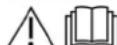
Ipeed nepim 3aocybaHHM npIcTpoO 03HaOMTeC 3 JcIO IHCTpyKJcEoEcknnyatauJI, DJIte
BⅣnobioHdo Ho Tei 3a Sepeirne HIO II nOanbIwO KOPNCTYBAHHA 60 do NACTyHNO BIAchnika.
Ypa3i BmBnEHHaTpaCnOpTHnx yUkOJxHeHb Blp43y npoiHΦoMpMyBaTN TopBOrO npdctABnIKA.
PiJ yac po3nakybaHHnepeBipTN BMCTynakOBKn.
IpeJed nePIMYBedeHnM B EKcNpyataLIO 06OB'3KOBO O3HaHOMTNCb I3 BkAaIBKaAMM 3TexhIKI 6BeNeK No 5.951-949.0!
Oxopoha doBknna

NakyaBbHmatepiAn npHaTaHi do BTOPHHOI nepeo6Kn. YnakOBky Heo6xIDHO yTNi3yBAtn 63 uKoDn IaJ doBkInnn.

EeKTHaT Ta eekTOHPi npCTPOI MCTb LiHH MaTePJIaN, kI pMaDiTHo BTOPHHOI nepepO6Kn, iCATo KOMNOHETN, kK-OT bATapei, akMyJrTOPn YMactINNo, kkiy pa3i
HepnabNboHO NOBODKHeHr3 HMM a60
HepnabNboHO yTNi3auiO MoYbCTOBpNT NOTeHcHny
He6e3neKyIra 3doOpBry IIOuHN Ta DOKBINJ OJNAK
U KOMPOHEHT NHeo6XiHi dna HaneKHO eKcnpyataJI
PnpCTPOI. PnpCTPOI, N03HaueHI cIM CMBONOM,
3a6OpOHReTcBcYTNi3yBaTn pa3OM iNobTyOBM
CMTTTR.
Bka3IBKNoDoKOMNoHeHTB (REACH)
AKTyAunbHI bIDOMOCTI npo KOMTOHETN HABeDEHHa
DdaTkoBa iHΦopMaui npo 3axnCT DOBknna
He Donnyckatn NotpannnHNA MOTPOI ONBn, Ma3yTu, DnEhBOHO nAINBa Ta 6eHNHb H BaKoNHIe cepedOuhe. Bepexitbpynti y tni3yTe BiDnpa2oBAHe MacNo ekONOrIOH cHtM CNOOCOM.
CNMBONHa npncTpoi

He cnpmoByBaTu CTpyMih BODn NID BWCOKIM TICKOM HA IIOJe, TBAPIN, YBIMKHE He nekTpHupe ObaHaHnry Hn Ha cam npctpi. 3axuataN npncpti biD MOpOy.

Hebe3neka yepe3 eneKtpnHy Hanpyry.
PoBoTn 3 eneKTPuHIO CICTeMoIO
MOKyTB BVKOHYBaTN TiIbKn
KBaIICIkoBAHI eneKTPknA a60
ynOBHOBaKeHH nepcoHan.

PonepeJxehn npo pniK 3aueMneHHN!

He6e3nKa yukoKeHnOuy Ta oprahIB cnyx. BnkOpncTOByaTH 3ac0b 3axNcTu Ouy Ta oprahIB cnyx.

He63eNaIgIaIbOoB'YpeE3TOKCHHI bIipnaIbOaHIraH.NeBdIXaTI bIipnaIbOaHIraI.
He6e3neKa oniKy oB rapaY noBepxHIO.

BukopncTaHHa 3a npn3HaueHHa
Bka3isKa
Diue HimeyuH: Ppucpi npu3aHuu mibku nro moBnHOo (He cnaioHaHoo) EukopcmaHn.
- Pnncptpi cneiaJIbHO npn3HaueHm IINBKKOPCTAHNR B MICx, De HMaE MOKNIBOCTIeKTPuHORO 3'EDNAHHN Ntpo16o 06p06nTnRAPaHO BOIOU.
OuNTKa:MaunH,TPaHcNpTmX 3ac06iB, 6yDibEnb, hCTpyMeHTiB, fAcadB, Tepac, caDorBOI IHBEHTApIO ToIo.
△HEBE3NEKA
He6e3neka mpaemyaHH!
y pali bukopuomannha h a emo3anpaehux cmauhjiax abo 8 HIXH Nbe6neuehX3ohax
Dompumyumebc biednoeihux npaeun mexhiku 6beenuk.
ByIb Iacka, He donyctitb notpannnHnMaCJHnCTnx CTHNHX BOY 3eMNIHOBOIMN A6O KAHJIa3lUIO. Tomy MNTTBAIryHa i DnHua cIi npoBODHTIN TInkBN PnICTOCOBAHx dIg YbOro MICx 3 yNOBIOBauem ONINB.
TpaHmHi 3HaueHHn IIN BOIOIOCTaauHHYB4A
3a6pydHeHa boda
Ipepeahe 3noeHnA abo biknaedHn a npcmpoi Dna ekcnnyamaui npcmpoE uKOpucmoeyamu nuue yucmy abo oboopmhy ody,raKe nepeeeuuc apAnuHx 3aueHb.
ДЯ BOДОПОСТаЧАнHA 3aCtOCOBYIObC Taki rpaHnHi 3HaYeHnI:
BCTaHOBHeHOrO yacy roTOBHOctI do po6oTH Ta nepeBmUeHNHa cay 6e3nepepBHorO peKxMv
Picna 3akihueHH BCTaHOBHeHOro yacy roTOBHOcI do po60Tm H6e3nepePBHorO peKIMy (45 XBnIH) eEeTKPOHa BmMkaepnCpTpi (3abOcbKe HanaWtYbaHH).
BidiobpaXeHHH HeCnpaBHOctI:ERROR14afo15
3an06iXHHnΦikcaTop
3anobkHnI kCaTOp Ha pyHOMy nCTOnetiP03nnIObAci 3anobirae BnnaKOBOMBy BBIMKHHeHHo npmctpOHO.
OrnA npnctpo
Onnc npnctpo

BiiBnBaU(306xCTopoH)
② 士日Kpuioka
KOM6iHOBAHnixTapi ranbmyBaHHraadiRaapnTHI liXtapi 3 NOkAXHcOM nobOpOty (NIBOPy)
④ BBeDeHnHaJnra npn 3akpnti 3adni Kpnu
(5)БлOKУВАнгЯЗднBoIКршкN
6HomepHH3nK 3OCBITnEHnM
KOM6HOBaHI nIXTapi ranbMyBaHHraHdIra6apHTNIixTAPI 3nokxKoKOM NOBOPOT (Hanpabo)
3axbaTHnna3nepeaHbOJ KpuuKn (3 06ox CTopin)
(9) ΓαδαπHη πιχταρί (3 oδοκ ΚτοριH)
10PtoTNbIDkoTnHyop
(1)Onophe kOJIeCo
(1)ΦikcyBaBnHrTaKn
13 WTeKepe He 3'cHaHHa nA OcbItHeHHa ABTomO6iHa
(14)BttgKHH TPOC
(5)Дишени.
10CTORHKOBeTaNbMO
(17)Baxjin3yennenHH
18 TpMaay wTekephoro 3'edHaHHa OCBiTneHHa ABTOMO6II
19 Pykib' onophoro koneca
20 BnokyBaHnnepeHbOi KpuiJHK
(2)Передна Кршka
(2)BxNtONHmOTBip
23ПиДИМОНБУБКО


1N3eBnHnDnRyH
②IpomixHmpeykTOp
3 HaocBncoKoTncky
(4)Пальнк i3azoбхнм 6лokom
(5BuxionHa Tpy6a
⑥ KomnHcauiHm6aok dIyoxoJxByBaIbHOI BOIN DInryHa
⑦ OTBip IaI TexHicHoro 06cnyroByBaHHpe3epByapy Ira BoN (nibopy)
⑧TobitpHnΦinbtp
9BaOcBkaTa6nHka
10 AkymytnaTOp
1Homep waci
②Hartay nBnHa
③PAnINBHHHnHacc
(4)ПpoToUHmBdoHaRpIbau
(5)TpaHcΦopMTop 3anaIHObaHn
16 OTrBip dIaTexHOrHO 0bCnyrOByaHaHHpe3epByapy dIa BOu (npabOpuy)
17 BaKДЯ MIMHOrO 3aco6y
18 OunneHHFinbtpaYBCMOKtyBaIbHOMyUHaHROBIMNIOHO3acO6y
19BCMOKTOUHNIUHNGNIMHOHO3ACO6y3 DaTHKOM pIBHA
(20)ДоЗувальни Кларан Миного 3acoby
21 BiDcik pIa 36epiraHnpyHoro nictoeta- po3nnIObaua
22Bicik dnn 36epirAHnCTpyMeHeoT py6kn
3] ⅢNaHT BVCOKOTUCKY
24 Bapa6an dna 7aHaRa BncoKoTo Tncky
(25)ABapiHnBmKau
26Kotuuka dnyu naHaHn3bkoro Tcky
(27) CMHICTbIaNnOM'kUWBya BODn
28 BaK dIaHTnФpM3y
29 3aINBHH nATpy60 k a3 p
30 KyIbOBn KpaH, aHTnΦpH3
31 HdkaicipBn 3anOBHeHHpe3epByapy DnBOn
32 BaK 3 nonJaBkOM
33 YnpabniHn HwBnKicT OoepTaHH
34 3aHHHn OTBip 6aka 3 KPNKIO/CMYeBnM
35OTBipDnAaNNBKnpiKoro nom'kUyBaHa
36 KyIbKOBI KpaH dJa NepeMMKaHH 3BOpOTHO NOtOKy
(37) BmMkau npnnaJB Ta cTapea
38 3axnchnn Jnct (npabopyh)
39 3axnchnn nct (nibopyu)
40 BnyckHn KpaH pe3epByapy DnBoDn
(4)3Ливнй Кран
42 Ⅲnahr nra anrnpnsy
(43) UlnaHn noJani BOIN
(4) Bóryn Hǎn PiīnbTp Hā BXOdi
(45)MaHOMeTp
46 liHia noaui antnnp3y a60 napkybaNBHe nnoXeHHN 3'ENHNN Hm3bkoT Nccky GEKA
47 3BOPOT CTPYM aHTNΦPn3y a6o npkyBaIbHe nONOKeHHH DnA 3'EDHaHH BnCOKOrTO TcCKY
48)Kpnuka6aka
49ПаньkepyBaHHa
PAnHeJIbKepyBaHHa
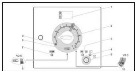
0/OFF = BIMK.
1Dinne
②BIMINKAUYnpiNCTPOH
③ CnHnHaBHa JAMnoUka, nonepedni nporpib (yepboHa)
④ CnHnHaBHa JAmnoKa,rotOBHicTbdoeknnyatauii (HePBOHa)
(5)BaMKOBIN BIMNKaH
6 PeKIMpoBToN《3HnueHn8byp'hIB》V2.0(onui HDS13/20,HDS17/20)
⑦ CnHaJIbHa JIaMNoUka, IpeEJa KpUka/abapiHHe BIMNKaHHa (HepBOHa)
8 Pekimpo60n3raepo/oxoioHO BOIO
9 Pekm3axnctyBid3aMepe3aHH
10 Pekmm p60ToK3HmueHHa 6bpYHbV V3.0 Ta V5.0 a6o pekmp60To KpeMn naporeHepaui (onuia dNHS 13/20, HDS 17/20).
D03BInbHI DOKyMeHTN
OdoBbHbDokyMeHTn Ha pNCTpI 36epiraTbC B W aF dnn enekTpnpnlaqIB. Wapfa zAMKHeHa dnn TpaHCNOPTYBAHN.
BidobpaXeHHaHOpMaIbHoro pexmMy:
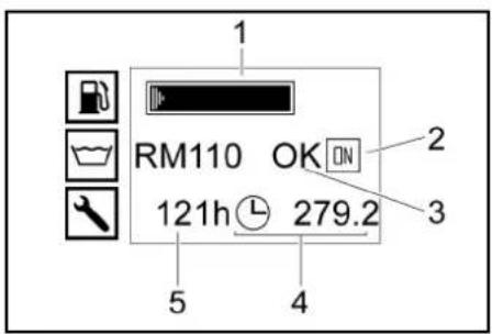
① PanmBnH 6ak (IINMkauiHa nnHa)
② DvBryH BkN. (ON) abo DvBryH BkN. (OFF)
3 BaK 3 pIKM NOM'RAWBAeEM RM110/6aK nI MHHoro 3acO6y CHEM (OKnopoxHn)
④ NiHnBnKpo6oOuNXrOuIN
⑤ FOnHH EKcnnyataaJi Do HactynHoro 06cnyrobyBaHHa
Bka3ieka
Ihduaua baka anu muhoao 3ac0y doomynha, minbu kuo paHue bno euaheHo, 0a 6ak dmuhoao 3ac0y noehicmio zaoheHu.
V HOpMaHbHOmy pexKmi pO6Omu Ha ducnneI cUcmemu KepyBaHHa nonepemHHo eioobpaKaemba maka InHopMaJia:
3auuHupekumpo6omu
TexHHHe 0cbnyoeeyAHH: Ooey3koepobomu 3 mexHIOO 0cbnyoeyeAHH, uO npOoBmcbcepeichoo cnyx60 (due. "OoJra ma 0cbnyoeeyAHH).
Jkuo cnld npoecemu deklnka po6im 3 mexhiHnoo ocbnyoeayehnmo eohu eio6pbaiaombcr no cepri.
JaIO mepMH npoebeHnpoBOM 3 mExHNoOo 0cbnyooyaHHne Hacmae, mo bioobpaacmcbn Hacmytnhe noBDOMnEHn.
HecnpaHicmb: Buukna HecnpaHicmb (cm. 100002 a p3i euhukhHeHH HepcnpaHocme"). Jkoo euhkno deiknbka hecnpaHocme, mo eohu eioobpaxaIomcb no cepsi.
Kkuo Hecnpaenocmi iDcymn, mo 6ioobpaxacmbca Hacmyne noeiodomnHn.
BIDo6paXeHH3axnCTy BID 3aMeP3aHH
1PAnBHH6ak(HnNkauiHa nnaHa)
(2) Pekim 3axncty BiD 3aMeP3aHH
Bucokohanipn niictonet
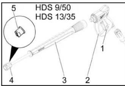
(1)3anobiknphiikcatopBnCOKOHnipHoro nictoeta
② 北cokohanipnni nictonet
(3)CTpyMmHHa Tpyoka
(4)NaKuNdra raɪka
⑤ Conno Bucokoro Tucky

① 3anobixhnnfikcatopBucokohanipHoro nictoneTa
② BuCOKoHAnipnHn nictonet EASYIForce
③ CtpymHHa Tpy6Ka EASYLock
④ HakuDha raiKa EASY!Lock
(5) ConNo BnCOKOr TnCKy
⑥ Perynatop TnCKy/BnTpHa HbBucOKOHanipHOMy nictoneti
73anob6iknBaxinb
⑧CnpyckHHBaxjib
YBDEHNA B EKCNJyatauio
△NONEPEDKEHH
He6e3neKa mpaemyeaHnra!
Ipucmpiu, oodamkooe obnaohnna, nHII niOedehnma ma 3cOhybHI enMeHmu nooHHi 6ymu y beoahmy cmaHI.
BcTaHOBHeHHI BnPiBbIOBaHH npCtpoYBA
Ipeepie npucmpo
YHukaume nepeepiy npunady.
IpekoHaumue, uO Micue cMaHoEeHHA
DocmmHbnpoepimpcm.
YB4A
Hebe3neka Henonadok ma yukodkeh npucmpoio.
Ipeo eknnnyamaue npucpiu Mae 6ymu eupiHnU eupuzohmanbHo.
Bn6epitbMICeEcknyatauTak,0o6He nepekPnBaBCBNyCKNHOnTBip.
1.3aikcybntc08HKOBe ranbmo
2. OnyctHTn onopHe koneco 3a donomoro Baxkena.
3. BiD'eHnBuTAAKm Tpoc BiTraa
4. BCTABNTIuTBePhe 3'6DHaHHN DnO c0BtIeHHN ABTOMOiIN Ta CTabNTIu B MlCe dNn 36epiraHHH Ha DIWIJI.
5.3akpinntnpnctpiJnra3anobiraHHMIMMOIBHOROCKOyBaHHN,niKJIaBUNiIbHbOrKNHHI
6. BiDuenTu Tgau.
7. BnipBHTn npHCTpi ropnHO tALbHO 3a DOnOMoHO onOpHOro Koneca.
BiKpBaanHra/3aKnBaHHn nepeHbOi Kpnk
- HatachynHaΦiKcatop NepeHb0f KpUuKn. PpeHdN KpuuKa BIDKpNaBaCTcB, CTBOpOOnu UINHHy.
- Po36nokyBAtn KICcyBaHbN rak, nOTIRHyBIM 3a HbIOr.
IpeHnKpUkAabTomuHBOBIDKnDaTbcHabePx.
Piud3aKpNBAHHcIkyBaTH3aTm,0o63adikcyBaBC.
BnryH
- 莱蔡伊图PiBEBOnMBDByHr.He EKcNpyaTyBAtn pncTpi, kAIO PiBEBOnMB OONyCTBRCNHeNo3HaNN «MlN」
- RaKIO noTpi6HO, DOnHTn OOnBy. (DINB. 《Dorna Ta TexHicHe oCnyroBvAHHH)
Ppomixn peykTop
- IpeBipTe pibeH MaCna Ha orIraDbOMy ckni npomixhoro peykTopa.
- Raio notpio6Ho, donuTo nOnBy. (DnB. 《Dorna Ta texHicHe oCnyroByaHHra)
Hacoc Bucokoro Tncky
- 菜椒BPTN pIBeH oniNBn Ha b6ky dny oINb a60 Ha uyni BmipIOBAHHr pIBH naOBn HACOCA BNCOKOR TCKY.
- Raio notpio6Ho, donuTo nOnBy. (DnB. DOrna Ta texHicHe ocbnyrobyaHHra)
OxonoJyUoHa pDHa
- Penebipte pibeHb oxoJkyBaIbHOI pIDHH B KOMNEHCaIHOMY BaKHy pN XOJHOHMy DBNrHi. PIBEb piINH NOBHN 3hAnoxDnTcMk nO3HAcKAMMIN (Min.) H MAX (Mac.).
- 阿K卍noTpi6H,DOnHTn OxonodKyBaIbHy piINHy. (InB.《DorTnTa texHnHe 0cCnyroByaHHA
- NpepeBipTe KOHcEHTpaIIO aHTnDppN3Y B KOMNEHCaIJHOMy 6aky.
- RaIIO nOri6HIO, OJIoTI NHTiOPn3. (IMB. «OOrIaT ATE TECHNIHE OCSNTOYBOVABHNAH)
NobirpHnH pInbTp
- NpeBipin noBIPrHn fInbtp.
- Aki noptipio, ouctntn/3amihtn noBITpHNI pibtp.
3aHHBaHH pikkoro nom'kyBaay
POM'KUyBaH eFekTHBHO 3aNo6Iae yTBOpEHIO BAHNHX BkNaJeHb HA cTINKAX 3MIoBNky npn BKNOPCTaHHI KOpCTKOI BOONPOBIHO BOIN. BIH OdaTaCn no KaPnI B npmMaHn KaHn baka 3 nonpaBOKM.
Ha 3aBoDIOZoBaHnBcTahOBJIeHe Ha cepEINO TbePdIb BOi.
Bka3ieka
Ipo6ha ynaokoka piko so nom'kywyaea exodum do KOMNkmy nocmaeku.
- Bldkniye 3aJIbHnI OTBip IaI pyiKoro nOM'IKyUbaA.
- 3anpaBnHnPiKIM nOM'kUyBaYem
- 3aKnipTe 3aJIbHHnO tBIP dIpyPiKoro NOM'kUbHaA.
3anpaBHeHHnabHm
HE6E3NEKA
Hepudamne nuae
He6e3neka 8u6yxy
3anaeamu e nanehu bak nuwe duensehne nanaue afo neaku mazm. Hnpudamne nanaue, npuknaad behun, eukopucmoeyamu zabopohemcb.
Bka3ieka
y pazi bukopucmaHHB ioduaeHbHo 5 B5 (eiOnioHO do eeponebcko cmaHApmy EN 14214) He bumaaemcbd ocmpumahn Oocbneux ymoecknyamaui, occyzoyaeHH mexHuHx po6im.
Bka3ieka
Y pazi eukopucmaHH bioo3eHbHOO nanuea B6-B20 (biIOIOHO do epeonec5ko cmaHapmy EN 14214) nompHi iIOeOIHI 3aoDu 3 nepeo6naHann HduEHOO DeuyHa. TaKox Heo5iHO
dompymyeamuymoeekcnnyamaui, mexHFOO 06cnyoeyAHnma eukohnHHmexHhux paBom. 3eepmaimeec a aeopupzoeany mopeoy kOMNaHIO Yanmar.
- BiDkPmT KpnKy 6aka
- 3aHnIe duIeBHe NaIINBO Uepe3 ropOBHy nAnIBHO6 BaKa.
- 3akpntn 3amok 6aka
- BntpiB npoJnte n3eJbHe naHBO.
3anOBHeHHMnOyOro 3ac06y
TinbKn HDS 13/20, HDS 17/20
△HEBE3NEKA
HenpuadamH Muoyi 3ac06u
He6e3neka mpaemyeaHHA
Bukopucmoeyime minbku npoykmu KARCHER.
YkoHomy pa3i He 3anueamu po34uHHuku
(Hanpuknaad,beH3un, aueemon, po3piOxyea4).
Yhukamu KOHmakmy 3 OyAm ma ukiipoio.
Dompumyamucb EkaekoEupbHsKa3 mexhiku 6beNku iBukopucmaHH MUHOO 3acoSy.
Bka3ieKa
UJHae bucoKoo mucky 3aXoDumcN iD mucOM 3aekou noBicmpo3momyme unHa bucoKoo mucky.
TinbHKHDS 13/20,HDS 17/20
Bka3jEka
Cucmema EASYLock dozaoJae uHadiu HcHyamu komnoHemu, noepmaoux y hapi3Homy 3cHhnni nuue ha odun o6epm.
Natpy6ok dJn iDBeHHeB ODo
PapameTpri ndknoeHnnaDb. no3diPi《TexHHXAPAKTECTMkn》
- PozmotaiTe 7nAhr nIy BODn 3 KOTyKn dnn 7nAnHa r iNkInOHT noauy BODn (HapnKnad, BODnpOBiDhoB).
3anOBHITb pe3epByap nra BODn
- Bldkprte noaay BoDopnpBIDHO BDOB B peseepyap.
- Pɔ3mOtaiTe ⅦnAHR DnI BODn 3 KOTyUKn DnI ⅦnHaRa i nkiNIOHITb NOaCyB OND (HapnKnad, BOIDopOBiDHOBn).
- BIDKpTNnnoaHyBoN. Peseepyap nna BoDn 3anOBHKeTcBcyepe36ak 3 nonlaBKM.Iicra 3anOBHeHHpe3epByapa nna BoN 3akpnTe noPbKBOnn KlananB6ky3 nonlaBKM.
- Ipekekpnt noaay BOIN
5.BiEHaTe WnAHR nBODn BID noaui BoN. - HAMOTAIte ⅢaHr DnA BoDn HA KOTUkny dIy ⅢaHnHa.
KepyBaHHa
△HEBE3NEKA
Topoi piDuHu
Hebe3neka budyx
He po3nunkoea mu ne2ko3aumucmi pidhu.
HE6E3NEKA
Eknyamaui 6e3 cmpymuHoi mpy6ku
He6e3neka mpaemyaHn
He ekcpnyamaeyam npucmpil6 63cmahoeneho ccmpymuho.
Ipeep KOKHM EUKOPUcMaHHaM nepeeipraUme MiHicMb Nocadku cmpmuHoI mpy6ku. Taunmoee 3'ednna cmpmuHoI mpy6ku Ma6 bymu zamrahyMe epyuHy.
△HE6E3NEKA
Cmpymh b odu bucoko0 mucky
Hebe3neka mpaemy8aHH
3a6oepohemcb fikcyeamu cnckhui 1 zaoobkhu aexeni epooymo nonoxenhi.
Heukopucmoeyamu eucokohanlpHnui ncmnon, Jauo nookoojeha 3ao6bXhuaaxinb.
Ipeep eukohannm oyb-kux poiim i npucmpoem nepcynmu 3anobiknui pficcamop bucokohaniphozo nicmonema enpeep.
Tpumamu bucokohaniphu nicmonemcmpymunhy mpy6ky o6oma pykamu.
YBAGA
Eknnnyamaui 3 npoxkhim nanuehum 6aKom
Buxio 3 naody nanauehozo Hacoca
Hikonu He zanyckamu npucmpi3 npokhim nanaum 6akom.
BidkpmbaHn/3akpmbaHn BncoKoHaipnoro nicToJeta
- BlKpnBaHHB NtBcOHOHAnIPOHOro NtCIOTeMa; HATChyTu 3nAo6bXHH Ta cyNckHH BaeR
- 3akpmbahnB Bucokohaniphoro nicToeta: BiDnyCTTN 3ano6xHH Ta cnckHN BaXejI.
3amihaconna
△HEBE3NEKA
He6e3neka mpaemyeaHnra!
Bucokohanipnui nicmonem 3haxodumbsra nd muckom. Ipeo zamHIO corna eumkhims npucmpiu ma hamukaieme bucokohanipnu nicmonem,doku epnpcmpo he dyde ckuhymo muck.
BmKHytn npiCtpr T haTnckcat BNcKOHAnlPHn iNCTon, DOKn B nPcTpo He yde ChkHyTO TNC.
2.3aΦiKCyBAtu BmCOkONJIpiHn iNCToTe, npeBIBiiu 3an0b6IeFfkiCtOp BnpeDe.
3. 3amHHTn conNo.
Iopaa BODn
Boda moxe noDabatnc a6o i3 30BHIhHoro Dkepeena 6o3 BHyTpiuHix pe3epByapib nna BODn (2x250n).
KynbKOBN KpaH nIpeMnKaHH 3BopoTHoro noTOKy
- Пложенна napаленинно наразмky pyxy: 3ворота BODA HACCOA BICOKOTO TNCKY y paal BiKpntorO nepenyckHOrо Кларана НадхodHTbdo baky 3 nonlaBkOM.
Bka316ka
Kko y bomy nojokhenkykbko020 kpaHy pyHu niomem-po3nuiokvay zakpuaebc, mo cep3 neepzieahnnpucmdoeumkhymucb 3a ekbnka xuunh (du. MuOJIOOMy y pasi Hecnpaehocmeu)/ERROR 3).
PonoJekHnepneHdNkUpHOn Hapmky pyxy: 3BOpTHA BOa HAcOCA BnCOKOro TNCKy y paai BiKpnToro nepenyckHOro KnaHa HaXdoInb Do 6aky dIra Boi.
3OBHIHNC BOOONocTaayHHA
- BCTAHOBHTBAXIKINKyIbKOBOrKaHnDnnepeMKNHn3BOpTOHOroNToKynapaneNbHOHanpAMkypyx(20n).
2.BnycknKpaH6kaDnaBODn.
BHyTpIuHc BOJOnocTaaHHr
- BctaHOBtIN BaXitIb KylkBOrO kpaHa dna nepemiknHaHH 2BOpOTHO rTOky npenHeNkynpHNo HapRmKy pyx (500 n).
- BldkniTe noauy BoDopnpBIDHOI BOIN Bpeepayap.
YbIMKHeHH npncToIO
Bka3ieKa
Pnpcmpi moKha ekcnnyamyameu minbku i3
3akpumio nepdehboo kpuko. y pazl eikpueaHnna
pepehboi kpuu npcpmiu npcpmiu bumkaemcbci
BmuKmbucra CuaHaBha NAMNOKA.
Bka3ieka
Oc oemamooho doocahennno po60oao mucky
yacmoma oobemmann deuyu na Moke 3mHoeamucna
peea npuec uudaneh noepimr.
- Pozhoknye KhoNPky abapiHoiO 3ynHHK, BBITaHyBnI II.
- BIDKpNBHRAaHbO KPNK
- BiHOBiB noauy BOn
- BCTABNTN KJIIOU y 3AMKOBIN BUMNKaY.
- Tɪbʌn pɪn xɔnɔdHɒm y ἀνβrHy Ili Nobeρhɪt kɪŋʊ b NɔnojxEHHI NɔpepeHbI O nɔpRyB dɪNyrH a NBIo i Tpymɪyte HɔrO B TAKOMY NɔnojEHHI do TmNip, NOKn He 3rAche CnrHaNbIa lamNoHcKa nɪdɪrpIbY.
- NObepHtB KInOu 3anaIIOBAHH B NoIOKeHH "I". CBTITbC KOHTPbHa NAMNOOcA «TOOTBHCTb DO eKcnPiatai#. BMNkAcTbc KepyUHa HApyra, a Ha dncnnei NOka3yETcb po6ooy CTaH.
- 點蔵HITb KIOU 3anaIOBAAHH npabOpy do 3aInyCk DByHya.
8.YCTAHOBHTI ROBOHBI BMMKau y NIOXOEHHA PEXMHY POBOTN 3 XOHOHDAI/TRAPOHO BOOO. - P036J0KYBATN BVCOKOHAPHNI CTIOJETON, nepeBBIIN 3ANO6KHNI fIKCATOP Haa3d.
- BiikpnBnCOKOHanipHn nictoJeT.
3XONODHOBODOIO
- BctahOBitB nepemNKaB u noIOKeHnRA "0/OFF(ΠηbHKNKBK).
Pexmpo60tn3rapyoo BOIO
HE6E3NEKA
Tapya boda
He6e3neKa onikj
Yhukamu KOhmakmy 3 zapraoyo 8doio.
1.YCTAHOBINTB BUMNKAY NpICTPOHO HA NOTi6Hy poOby TeMnepaTyP (MaKc. 100°C). PAnbHMK 6yde BBIMKHeHO.
YnpabJIHHsWbNdkicTIOo6ePaHHa
- Raio nprictri He npauooe BnpdoBx kInbKOx TnKHB npn CnHbOMyPO3O, 3HRTn AkyMnTOp Ta 3eBiPArno HBoMiCz, 3axuHcEOMy BldMOyO3.
LuklIyHe npOMBaHHaHTnΦpH3OM
(BNCOKOHAnOpHn Haoc)
- PnB OBONoCTaYAHII BID 2OBIHbIbO JxKepeNa BID'eAnthe UoANH for BOIN BID nOaH BIOn.
- BctahOBiBtIpepeMnKauB nnoJoxeHHa "0/OFF" (PnabHnK BnKn.).
- CkHHTN TnCKy npncTpoi.
4.BCTAHOBITb BIMKau PNcIPTOBO NIOJKeHHA 3XACMtBIDaMEp3aHHa. - TintbHK HDS 13/20, HDS 17/20: BCTAHOBHTN D03yBaJIbHm KIanaH OHCHORO 3aoc6y Ha MAKcIMYM. BImITB IuHaRf MIOHO 3aoc6y 3 6kA dN MIOHO 3aoc6y i pO3MCTITb Ioro TaK, 6o6 6yNo 3a6e3neHoe Ioro nobHe BNOpOxHEHH.
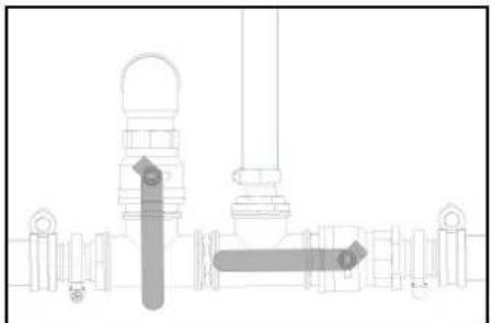
6.YIMKHTIb NOaCy BOiN B peseepyap IIN BOI iBIDKPNIte 3nBBH KpaH,IO6 NobHcTIO CNOPOXHNTPiNCPTPI.
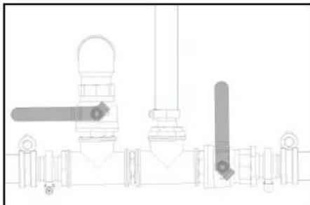
PLOKAKM PIBN HPESEBPUAPA DNR BOIN OYCKAETCB NOBHCTIO.
7. 3yninHtB noaHy BOnB Bpe3epByap dna BOni 3akpnTe 3nBHN KpaH.
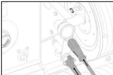
8. BID'EDHaTHBnBCOKOHAnIPHNPiCTOnET BID WnAHRABNCOKORTO NCKY.
П.Дклочьшанг Всокого Тпckу Дднодаи anHnФрз.
<|im_start|>assistant
АннФрз.
10.Пдкнioчышангдя nobephenhaantnФрmay.
11.3aHnTe aHTnFpnnB 6ak nna aHTnFpnn3y. BnBepeIb cIIIBIOHOeHHRA cyMIUI BOIN/aHTnFpnn3y BiIOBOIHNO daaHNx BnPO6HnKa aHTnFpnn3y.

12.ПepeBipTN KOHcEHTpaIcAHTNcpn3y 3 BKNOPCTAHHMM CTAHDAPTHORO TcTePApDnA aHTNcpn3y i,RAIO Heo6XiHo, BIKoHaTn KONIPYBaHn.
13.BikpTNOTBIPnHANOBHEHH6aKa3NONNAKOM DnIyOIONCNAbTe BnHT 3HaKaTaNHOROJNOBKO Ta 3CyHbTe KPNKU BnIBo.
14.3aHTn20nTIPB aHTnCpPn3y B6ak 3 nonnabkom i 3akpTN 3aJIbHm OTbip.
15.BctaHOBtB BaxjIb ynpabJIHH KynboBOrO KpaH aHTnФpN3y ByePTKanBHe NOJoxHeH.
16. BCTAHOBINTBAXIKINKKBOKOROKPANA HnepEMNKAHH3BOPOTHOROTOKYnapaneNbHO npampykpyx20n).
17. TINbKn npn XOJOnHOmy DABRHyI NObepHITb KNOU B NOJOKeHHN ONEpeHbO rnporpiBHy DABrHy HAnIO I yTpMMyE Noro B TAKOM NOJOKeHH Do Tnx nip, NOKn HE 3raChe CnHANbHa NaMOnOHa nIDpirbY.
18. NobepHtB KnOu 3aJIoABoHH B NOnoXeHHN "I." CBrITbC KoHTpObHa nAmNoKa «IToOBHcTb Do ekcnnyatauij). KepyOua Hanpyra BMKaTeBcI, a
- DAtn npctpoO oxoNoHyTN.
OuHHeHHBODaHOroΦinbTpHaBaXoDi
- 3Hrtn BoaHn HJIbTp Ha BxOdi Ta BNTIHyTn NaTPOH FJIbTpA.
- OCHNTINATPOH OPBILTPY UCHTOO BOQOKU NCTCNHYTM NOBITPDM.
- 3HOBy 3i6paTu y 3BOPoTHiN oCnIIOBHOCTI.
OuHnHHa pIbtpa nonepeHbTo OunHn
Hacoca
-
CkHHTN TCK y npncTpoi.
2.3HnTfNtbpTneoneDhBOrOOnuIeHHA HAcocTa 2BHTyHNtNaTOHΦNtPa.
OCTHNTNATPOH qinbtpy CHTOQ BOAO CHNCHVTHM NOBITPAM. -
3Hoby 3i6paTu y 3BOpOTHi nOcniIOBHOCTI.
OuHHeHHa pIbTpayBCMOKryBaIbHomy HnaHry MIOOyOro 3ac06y
- Bɪdkpyrɪtɪb piːb6əby kpiuiky ycmokTybaɪbHoro shaɪra mɪnɔhʊr 3acɔ6y.
- BuntarHb BCMOKTYBaIbHn IJHaT DnA MIOHOFO 3aO6y.
- PpomnTe pInbTp y Bodi i BCTaHOBtBa Mlue.
IpeBipka pIBHa Ta dONBaHHa MToPHOI OINB
Bka3ieKa
PieeHb 3anaoHeHHa mix no3naHuKaMu MIN ma MAX ha uyni cmaHoobmb 1,6 nipu.
- BntTn uyn, BNTeptn i 3HOBy NOrO BCTaBtN.
- Ⅲe pa3 BITIaTn Uytn Ta nepeBipNTn PiBEh OINbN. PBeHb OINbN BnpAky, kIO B IH 3NaXoDnTbc B MEXax No3HaYOK H Auyni
- RaIIO pIBeHb ONBm 3hAoxOHTCBn HNXYe N03HaKN, CII D BIKPNTKpINIKy 3aINHBORo OTBOPy I aINTH CBIXY MOTOPHY ONBHy.
4.3aHeKATN P'YbXbINH, NOKMOTOPHAONIBA 36ebETBcB INIIOHoi - NpebipntpiBHeOINBn, Rk ONuHa Bnue.
- NOBTOPOBATMIOPOLEUYPDTOJOKINPIBHeONBIHb YE BDEyBE MEXAKOENHAHKNHaUYNI.
7.Пспа néверікі ВBSTAVTN uynl i zakpNTN kршky ZaJIbHOrO TOBpy.
Bka3ieka
Cnlo3a6e3neuTu moXnueiBcEuxOyDyIb5auok nooiprr.
Bud macna 6ka3aHO 6 po3di "TexhiH daHI".
IpebeIpe pIbeHb MacnB npomXHomy peyKtOpi IdoHNTE TpaHCMIcHHe MacNo
- IpeBipTe pibHb macHa ho ornIIOBOmy ckni npomixhoro peykTopa.
PbEbn Macna 6yde npabnBnHM, KOHN B3xHaoDbnc oNcepeDnOrIgDorBOrO cKn
2.Якшio pIBeHb macna HnKHe cepeDnHOrIgTIOBOrCKNa, BiKpNHe KpnHKy 3aJIbHOrO TOBOpYi 3aJIbHTe CBIXe TpaHCMIcHne MACno. - 3akpiTe 3aunBnO Tbip.
Bka3ieka
Cn# 3a6e3neuTu MoXnueBcMb euxOdy 6ynb6auok noimpr.
Bud macna ek3aHO 6 po3diNi "TexHiHa diH".
IpeBipka pIBH OINBN YIOM HACOCA BNCOKOR TCKy Ta DOINBaHH OINBN
- BnKpyTNTuyn, BuTeptTu 3HOBy BCTaBtN.
- Ⅲe pa3 BnKpyTm Tyn Ta nepeBipn TpiBHeb onMBn. PBeHb OINBn B Nopdky, kIIO BIh 3NaXoDntbcB Mexax No3HaYOK Ha YUni.
- Raio pibHeb OINBn HNxue No3HaKn Ha yni, HAHTN CBIXOJNY
4.BkpyTnTn yyn
Bka3ieka
Cnlo3a6e3neuTuMoXnueiBc8uxOy6yIb6auok nooiprr.
Bud macna 6ka3aHo 6 po3di n "TexHiH daH".
Ipebpka i donuBaHH oxoOnOxyBaNbHOi pINH
OSEPEXHO
Mozymb ymeopoeamucu ukiidnui peoouhu.
3eepmaume yeaay Ha Mapky eukopucmoeyaHozo ahmudpuyu.
3miuyehnMoKe cnpuuHumu ximHy peakujio. He 3miuyume pisi Mapku ahmuppuy3y.
△NONEPENKEHHA
He6e3neKa nepeapiy dueyHa.
Daeyn6e3 oxonodxyaanbhoi piuHMOKe
nepeapimuc.
Hezauno 3ynuHmu deuayi damu uomy oxonohymu.
△NONEPEDXEHHA
He6e3neKa nepeapiy duyuyna.
IaBvH 63 oxoNodkyaeanbHOi piDUn HO meKpeepzimpu.
Kkuo deuynneepaiecnaemibku,uo buxodum beoyna napa,mo deuyun mpeba zynuhumu ipmumucz bid hboe na he3neyuhi eicmahi, noku He 3mehuumc uck.
YBAGA
He63eKeA ownpo8aHnO oxoOxyaenbHO pioHO oaoyua
KOMHeCAUHui 6aOcK 3haxoDumcbn iid muckom. 3a6opohEmbc iidkpuameu kpuukyHa KOMHeCAUHou M6aCyI dnyoxoKyaeBAnbHOi pIDHU duzyHa 3a poOoYi memnpamyu.
- BIDKPHTN KPNWKY HA KOMNEHCAUHOMY 6aKy dny OXONIOKYBAHbHOI pINHH DBNYHa, DOJNTN CBIky YnCTy BOy i BiNDOBHN aHTNΦpN3 Do nO3aHuK Max.
Npebipka/ouueneHH noBITpHoro fInbtpa
Bka3iKa
Ipyb6oO OuUeHnO BoimrHoo oIbmpa MoXHa Niocmaeu Mu CMHcB n36upaHHn Dn 3nue ocady iEUKOHAmu OUeHnH.
Bka3iBka
Cunbno 3a6pyhnei a6o hncpaan hi pamoH oIbnma OponuHI bmyu ZamHeH.
- NocaaBnIpyKxHnHy 3aTckNcKcb6y,3HNTn KPNKUbI BVDaNITBIBDknaDeHHnYnHJ.
- BnHrtn natpoh fInbTpY.
- Pódytny natoPno fiJIbTpa 3cepeDnHn CTsHeHMM nobTpam (Makc.26pa).
4.OChntnKopnycNoBITpHoroΦInbTa3cepeHHraHHPKIO. - BCTABTe pInbTpByaBHy KAcety B npctpii.
- BctahobHITb npomKHy kmpKHy i zakpinitb T pykHHBtBaTcHKHO CKo6IO
NpeBipka KInHOBOPeMeHBeHTnTota
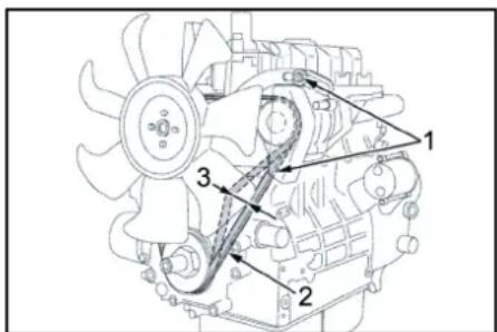
1Kpinnblhi FBINTHrEhepaTopa
(2)KlnHOBm peMInb
(3) Hata rpeMeHn np6n.7-9 MM
Bka3j6ka
Kkuo Knuhou pemh hedocmthb hamayumu mo moxe iibdbmcna nepeepa duyha a6o akymnstopapdumcne He noehicmo.
- 3yIMHHTDIBYH I BITRTN KIOH 3aMKOBORA BIMKNAH
- Ⅱo6 nepeBipTu HataR KInHOBOpeMeHn, HtNCHTu BeINKIM NaJIbCeM Ha peMiHb MIX IUKiBAMn.
Bka316ka
Klnuohou pemH noeunen emuchymucb np6n. Ha 7-9 MM.
Bka3iBa
3amihumu nowkodkehi knuhoei peMeHi.
3mauyBaHHI HepuHoi ralmbiHOc nCTemnpuena
- Ha 06bx 3maUyBaIbHnX HInenJx 3a DOnomorOTo CTaNAdTHORO 3maUyBaIbHoro Upiuza 3aInTN BINNOBIDHe MaCTHIO.
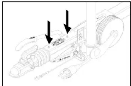

MaulyBaJbHn HIneB
IpeBipKa Tncky B uHHax
- NocTabNTn npCTpi Ha pIBHi nobepxhi
2.Плкючтдо BEHTINЯ WINNпрстридяпелбИрКИ TUCKY B WINHAX. - IpeBiptnT Ntck nobiptp (JMB. 《TexHHI xapakTePCTMnK)》i3a Heo6XiHocti BkOpinyBAtn.
3amHa koneca
HE6E3NEKA
He6e3neca dna kummpeeaepedopoxhi pyx
PidvacpooeedeHnpeoHmHuxpobimHa doopoza 3aaIbHo2o KopcmuyeHn npkUyme npcpmli Ha pieHNI noepexPHMa oBaAaumcuuaHua
- 3ynHHn npncptpi Ha pibhi nobepxhi.
- NpeBipnTc tniKtctb NOBepxH, DODaTKOBA 3aΦICcyBaTN MaunHy BiD iBKOuyBaHna 3a DONOMOHO KJInA.
- 3aΦikCyBaTn cToRrHKOBe rAJIbMo.
- NpebipuTu uHn.
- NpeBipTNnpoTeKTOp HmH Na HbRbCTb B hOmy CTOPHOHN XpeMeTb.
- BvdaHHTn CTOpOHHi npedMeTH.
- BnKOpNtOByATnPiXoJraaTnCTaHdAPrTHn3ac6I IaIpeMOHTyIHH
Bka3ieka
Dompumyeamucpekomehdauiiiednoeiidhoe eupobhuka. Iodabhuu pyx moxnueui nuee 3 dompumahnem kaeiaek oupobhka. Ppu nepuiu moxnueim npoeemmu AMHy uhu abo koneca.

-
BCTAHOBITN ABOTMO6IbHN DOMKpat Y BIDNOBIDHONOPHI TOUJI.
-
Nocna6te konichi bontn.
10.ПИДНМашнHy 3a ДОпOMоRоДОмКрАТa. - BURBHTb KOJIcHl BoNTn.
12.3HRTN KOJNECO - BctaHOBnTH 3aNaChe KOJecO.
- BCTABTe KOJIcHi 6OJTn.
- OnyctntMaunHy 3a DonomorOIO DomKpata
- JInbHo 3aKpyTtB Konichi 6oJTN no diarohani.
Momet 3atryBaHH
110-120HM
Bka3ieKa
Domkpm He exodumb e o6ca nocmaeku.
Bka3ieka
Bukopumcmoeyeamu npudamhu cmahdapmhu domkpa.
Pnue
- DopyaIte peryIyIPO nepeBipTn ranbMIBHy cnCTemy ta waci Ha ophiuiHn CTO.
Donomora B pa3i HecnpaBHOcte
△HEBE3NEKA
Henaemuchu 3anyck npucmpoio
Hebe3neKa mpa8My8aHHy, ypaXeHHra enekmpuHUM
CMPYMOM
Peped npoeedeHnM byob-skux poibm Ha npucpoi ecmaHoemu zamKooueumuk4 nnoKeHHA 0 H eumraaKnHou.
△HE6E3NEKA
Henaemuchu 3anyck npucmpo, domuk do qacmuh, o npoeodmb enekmpuHu cmpym
He63neKa mpaemyeaHn, ypaekHH enekmpuHUM cymPOM
Ipeep npoeedeHnRm poib h npucmpo eumkHymu npucmpi.
Bumremu umencenbHy uunky.
△HE6E3NEKA
He6e3neka 8b6yMa KOpomKozo 3aMukAHHa. He kAncu ImcmpymHu a6o nodIh npdeMmu Ha aykymnHop.
1 DAn npncToPO oxoJHOHTN.
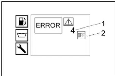
OTo6paKeHne HeHcnpaBHOCTn:
KIO IOKOKeHH He MoXHa yCyHyTn, Heo6xJHO nepeBipTu npCTpiy cyepich Cnyk6i.
HecnpaBHOcti 3 BiO6paXeHHMa HnCnnei
Bupi6: Muyohni anapat BmCOKORO TUCKY
Tun:1.524-xxx
Tun:1.999-380.0
BiDnOBiDiHn DnpeKtnBn EC
2006/42/EG(+2009/127/EG)
2000/14/EC
2014/30/EC
2014/68/EC (onuia)
3acTocOByBaHI rapMOHl3oBaHI cTaHdapTH
EN60335-1
EN 60335-2-79
EN 1829-1
EN 1829-2
EN ISO 12100
EN 13309:2010
EN 55012: 2007 + A1: 2009
EN 62233:2008
3aTocOByBaHMeToD ouiHKBIDNOBIDHOCTI
2000/14/EG:Додаст V
PIBEh 3ByKOBoI notyXHocti, dE(A)
HD 9/23 GeTr1 + HD 9/23 DeTr1
BumipraHn:105
TapaANTOBAHm:107
HDS 13/20 DeTr1
BmipraHn:97
TapaANTOBaHn:100
HDS 13/35 DeTr1 + HDS 9/50 DeTr1
BmipraHn:100
TapaHTOBaHn:102
HDS 17/20 DeTr1
BmipraHn:100
TapaHTOBaHn:102
OPTIONAL
Bupi6: ABS napa HDS 1000
Tun: 2.013-093.0
Kateropia By3na
PpoeDpya ouHKn BiNobiHocti
Modynlb H1
HarpibaBHH 3MiOBnK
OuiHkaBIDNOBIDHOCTMOyH1
БлOK керУВангЯ
OuHka BiNobiDHOCTi Moyra H1
P3Hi Tpy6oBpOBoDn
OuiKa BiinobiHocti, CTATT4, nyHKT 3
3actocobya hi cneuikaii:
BIDIOBIDHO AD 2000
BIDIOBIDHO DO TRD 801
Ha3Ba oprany 3 ceptnΦikaui:
2014/68/EC
C013 opraHiaui He3aJeXHoI TexHiHOeKcneptn3N

H.Jenner
Chairman of the Board of Management
S. Reiser
Manager Regulatory Affairs & Certification
Oc06a, BiDnOBiDaIbHa 3a BeDeHHa DOKymeHTaui:
71364 Winnenden (Germany)
TeN.: +49 7195 14-0
ΦaKc: +49 7195 14-2212
3aunTa Ha OKoJnHaTa CpeDa

OnakobbUHIne MaTePnAInu NoDnEkaT Ha peuknIpaHe. MoNJI, n3XbBpJrNe ToaKOBKnTe NO cbo6p3eH c OKoNHaTc cpeDA HauHn.

EeKTPuueckTeIne EeKTPoHHMeYpeDnCbIbPxat UeHNMaTepaAn, NpDNeKaHuaNpeUKNipae, a cheTo n CbCTaBm YacTHn, Hapn.
BatePn,akymyataopHn BatePn nIi MaCIO KONTO npn HnePabNHO bopabeHe nIIN 3xBbPnHE MOrAT da npeCTaBnBAT noTeHcunHa onAChOCT 3a OBeWkoTo 3dpaeN 3a OKoHATA cpea.3a npabNtHO FOHyKMOHpaHe Ha ypea BCE NaK Te3n CbctABn Yactn Ca Heo6XoDmM. O60haueHnTe C To3n CmBON YpeHn He Tpr8Ba Da 6bDat N3xBpNn H3aeHNO C bHTOBNTe OTNaDbu.
Yka3aHnna 3a cbcTaBnBeuecTbA (REACH)
AkytaHnIHΦOpMaIa3bCSTbMKeIteHAMEpIte HnHTePepTcSTpaHua:waKaercher.de/REACH
DonbIbauyn yka3aHnna 3a 3auHnHa OKoHNHata cpea
MOnr, He OnyckaTe MToTPOH MaCNo, Ma3yt, Dn3eNoBO TOpRbO N6e3Hm Da NoNaTa B OkOHaTa CpeA. MoNr, na3eTe NoVbTa Nx3BbPnIe CTapntE MaCnA CbObpa3Ho C ekONoFnuHte M3NCKBaHN.
Cnmbonn Bbpxy ypea

He hacooyte ctpyraT noD BVCOKHO HnIaHRe KbM XOpa, JMBOTMH, AKTINBOeKtpruecko OobpyBaHe IIN KbMa Cammy ype.
Ia3eteype da 03ampb3BaHe.

Onachocn nopadne neneKtpuececko Hanpekhenne.Pa60tn no eNeKtpnueeckata Hcctanaunna Tp6Ba da N3BbpuBat camo nEeKTPoTeXnucu nnOpTnupah Cneuaaninupah nepcohan.

IpeDynpexdene 3a onachoc ot npuiinbahe!

PncK OYBpeKdAne Ha OUnTe N Cnyxa. HocTe 3aunTa 3a OUnTe N Cnyxa.

OnaCHOCT3a 3dpABeTO npopAdn OToPBOHn Otpa6oTeHN raOBe. He BmUWBaHTe Otpa6oTeHNrTaOBe.

Onachoct O n3aphe Nopadn ropeu npoBbpxHOct.
Ynotpe6a no npedHa3HaueHne
yKa3aHue
Baxu camo 3a TepmaHua: Ypeobm e npedhaNauhen camo 3a npehocuma (hecmaquohapha) ynompe6a.
- YpeBt Ce 3nON3Ba eNeuaHIO TaM, KbTeO HMa Ha pAnoLoKeHne nEeKtpueCko CbPbBAHe n Tpa6Ba Da ce pa60ntc o ropeu Boda.
IIOUCTBAHE Ha: 3a NOHCTBAHE Ha MAJIINHH, ABOTMOBNI, CRpAI, INCHTPyMeHTM, FACaIIN, Tepacn, PAHINHCN PnHAAJNEXHKOHTN I T H.
ONACHOCT
Onachocm om HapaHraehe!
Ipyu npompe6a ha 6b3unocmauu unu dpyeu onachu 3ohu
Monla, cnaaalme cboemaemhme npaeuna 3a mexukama h6e0nacnochm.
MoJn, He DOnyckaIte NonadAHeTo Ha cbDbPkaUHTe MInHepaHm Macna OTnAbbYbOuBn BNoVBata, BDHnTe 6aceHHIN KIN KaHAn3aHrta. To Pa3n IpnHnHa, MoJIa, INMBAuTe DBNAteTn IdoHtA TaCT cAmo HnIOxOJaMn MeCTa C PpeuHcTbaHa He MaCJTO.
TpaHmHn CTOnHOCTn 3a 3axpaHbHe C BOda BHIMAHVE
3ambpcena 6oda
Ppeeepemno u3nocaane unu omnaaun e ypeda 3axpnaeaume ypeda cmo cuaema unu peuknupana 6o0a, kOAMo He ppeuuaea epaHUnHume cmoHocmu. 3a xazpaHbAHeto C BOa Baxat CneDnHTe rpaHmN H CTouHOCTM:
| ph-стонoc6,5-9,5 | |
| eilektrinyecka провимоct | провимоct пося вoda +1200 μS/cm |
| утаяваши се вescьта** | < 0,5 mg/l |
| фильtripаши се вescьectorba*** | < 50 mg/l |
| Бълеворodopeni < 20 mg/l | |
| хлорд | < 300 mg/l |
| салфат | < 240 mg/l |
| калци | < 200 mg/l |
| ОвSETS Тьрдост | < 28°dH< 50°TH< 500 ppm (mgCaCO3/l) |
| желяzo | < 0,5 mg/l |
| манган | < 0,05 mg/l |
| мед | < 2 mg/l |
| актувенхлор | < 0,3 mg/l |
3aHTeH nKIOuBaTeI npedeH Kanak
- YpeBt Moze da cye Nbe B Eeknloatauca na, oAk e 3aTbOpEn pneNnHr Tkanak.
Ako npednna Kanak bde OTBpeH NO Bpeme Ha pa6oTa,ypeDbTe ce N3KnIOuBa n KOHTpoNHaTa NaMna Ha npednna KaanAabapnHO N3KnIOuBAHe CBeTN CepBEHO.
PpeINBENBeHTnI
- UMOCE3aTbOpnNtOeTAaPbHOnPbCKeA,ceOTBaprnpEiMbHNBaBHTINNOMPaBcKOKeHnArahe OTeBxaDObataoBpaTHoBpe3epBoapa
c nonnabb. IIO Tozhi Nauhci nepeoTbpaTaB a neuwaabaHa He NaoyctiMOTO pa60ToH NaIa
- Camo HDS 13/20, HDS 17/20: Pn haamaiaBahe Ha KOJIHcEeBTO Ha BOdata c peryIpaHETO Ha HANrAHaTeO/ KOJIHcEeBTO Ha pUHnR paAsnpbckBaTeHeN NtCToTnePpeINHnR BHTnO tBaPn I eHa YAcT OT BOdata M3TuHa o6pTaHO BpeepOaPc nONnabK, CbOTB. pe3epBoaPnTE 3a BOda (CnopeD No3uHnA Ha cpePnHnK PaH, PpeBKnOuBATEn HA O6paTHnNnotOK).
IpeINBnHrBENTnEpaBpHuHOHaCTpoEHnnom6upan.HactpoKa cmoB cepBu3a.
PpeDnaeHKnanaH
- Pnpna3HnT KnAnAH ce OTBapr, Ako npenmbnHRT BHeTN, peCn. NHEBMaTHNHT pKeKbCBa e deΦeKTeH.
PpIeIa3HHT KIaanA eFa6pHNO HAcTPOeH IINOM6paH. HAcToIkaTe ce I3BbpuBa cAmO t CepBn3a.
KoHTpOHa 3aPdHnTOK Ha aKymyIaTopa
Pn HeOCTaTbueH 3apJeH ToK Ha DnHaMTo npn 3apeXdaHe Ha akyMynaTopaypeBcTe mKnIOvBa.
DucnneHenn3npaBHOCT:PPEUKKA1
TemnepaTypeN KOHTpon, BXOJ 3a BOda CbOTB. OXnaKda BODa
AkoBxoDnHATAtempehpatyaHaBODaTaHADBmMakCMAmHOnDoNYCTmAta Temepatypa,ypebTceIKNIOvBa.
Ako TEMnepaTpyata Ha OXnaJdaauata Boda HADBnMakcmaHNOdoYctmMaTa TEMnpaTypa,ypeDbT CE 3KfHObBa.
DucnneHenn3npaBHOCT:PPEUKKA 3
3aunTaOT HeoCTnHa B0da,pe3epBoap c
nonnabbk
PpndnataNTeTnpOTBHeDcTnHaBOda npDTbPaTaBA BkIOHbAteHO Ha DBrTeTn PnHcOCTN HA BOda.
DncnneHennpabHOCT:PEUkA4
IpeNa3HTe IpoTnB HeIOCTnR Ha BOa Ha ropeKata
- PnpahtnptnoB nncsHa B0a (ctpyeh npkcbau) npoTbpataBa npperpaHeto Ha ropekata npn HeocntHa B0a. Tpekkata cTapnpca Camo npn DoctbHoo 3axpaHbae C BOda.
Dncnnne Hen3npabHocT: PELUKA5
ByToHEn npeKbcBa/ctpyen npeKcba
KOMBUNHANJRA 6yTOHEN PNEKCBW/CTpyEH npekcbwH3KNIOVA ypea npn HNOCTNR HA BOA pecn. YTEHCA.
DncnneHennpabHocr:PEUkA5
KoHTpOJ Ha paBnIeTo Ha IbJIHe He ha TropBO
Pn HeoCTnHa ropBO (pe3epBOapbT 3a ropBO e npa3eH)ypeBt Ce nKIOUba.
YKa3aHue
Pocepcmeom u3kn./kKn. Na ypeo maou moke da npobbnku da paabomu 3a 5 Mnuymu,doKamo peeepoeapb m3 zoepue e HantbHno npaeH.
Pn DepeKeTeH DaTcHK 3a rOpNBO ypeBt Ce HKNHOuBa.
Dncnnne Hen3npabHocr:PEUkA 6
HaHraHa MoTOpHTo MacNo
- BytoHnHrT npekcbay NkNHOBA dBMRATEA npn CnaI NOI MHHMAMHOTO HAIraHE HA MOTOPHOT OACIO.
DucnneHenn3npabHocr:PUEUKA7
OrpaHnHTeHaTeMnepaTpyTaHa oTpa6oTeHrTe ra30Be
OrpaHHTeTnHa TEMpePaTypaHa Otpa60TeHnTE Ra3OBe 3KKnHbBa RopEnkata npn DOCTInaHe Ha TbPDe BnCOKa TEMpePaTyHa Otpa60TeHnTE Ra3OBe.
Dncnnne HenanpabHocr: PELUKA 9
KoHTpon Ha TEMnepaypata Ha rOpEnkata
Ako TemnepaTpyata Ha BODATA Ha n3XoHa H ropeKaTa HauBnH MaKcMnBaH OOnCTNMA TEmnpaTpy,VPeBt N3KIOUHO RopEnkTA.
- Pn DepeKTHa TeMnepaTyPha coHda ypeBt NkIOuOBA ropeIkaT.
DucnneHHe3npaBHOcT:PEUKKA 10
CnCTeMaTa 3a Ha6JIIOJeHHe Ha IJaMbKa
KoHTpOJbHT Ha nnAmbKa n3KnIOyBa ropeNkata npn HEn3npaBHOCT Ha ropeNkata.
- DicnneH Hen3npabHocr: TPEUKA 11 pec
NkIOUBAHe CneI npeBnuaBaHe Ha BpMeTo Ha rTOBHOCT 3aEcnJNoTaUNa, Pecn. Na HENPeKbCHaTnpeXIM
AkoBpemeToHa roTOOBHcT3a EKcnIIOataunpecn. HnHepeKbCHAeTnpeXMMOT45MHNyTN6bJe npeBnIeHo, eNEKTPoHHKaTaHa ypeDa ce NkIOHOBa (pa6pnuHaCTpoHa).
DncnneHennpabHocr:Ppeka14cbotB.15
PpeIpa3eH 3aIbBaU mExaHn3bM
PpeNa3HOTo CNpauHO 3b6HO KOIeNo HA NtConeTa 3a pUHO npbckAne PpeOToBpaTBA HeBOHNO BKNIOVAHe Ha ypeA.
PperneHa ypea
OncanHe Haypeda
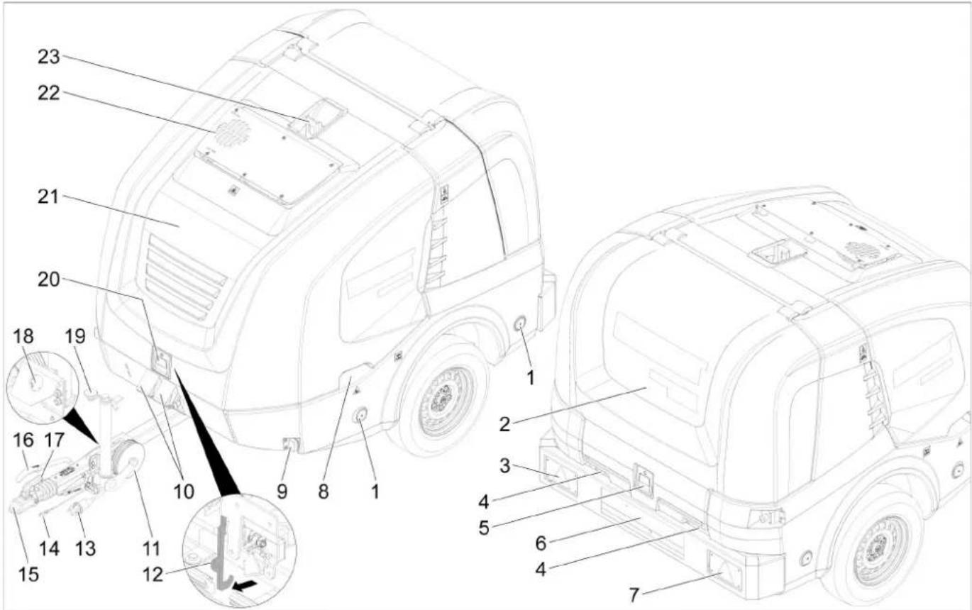
① PeΦπeKTop (ДуВТРанен)
②Baen Kanak
③ KOM6HnHpaH CTOn/3aHn CBeTnHn C HnDnKaTOp 3a Nocokata Ha DnKHeHne (OTnBO)
④ Ппекарвано на маркуда пи заюрени Кадak
⑤Блokировka заенkanak
6 O603HaunTeHnK cocBeTneHnE
⑦ Kom6HHnHpaHn CnHpaHn/3aHn CbETnHn CmHraHn (BDACHO)
8Ydb60eHHe 3a XbaaHa Ha npednna Kanak (DbvctpaHo)
⑨Ta6apTTHCBeTTNHH(DByctpaHHO
(10)POnIOJKeH KJIINH
(1)Onopno koneno
123axbaTHa Kyka
13 电eHNO cEduHeHne OCBetJeHne Ha npEBo3HOTo CpeDCTBO
(14)OcnHypntEnHO BxKe
(15)Пουцета.Terne�е
(16)3actonopraa cnpaupa
17 NocT 3a KynnyHra
18 1bpxa3aIeNcENHO CbeEINHeHne 3aOCBeTneHne HnpeBO3HOTcpeCTBO
19 Onopho konieno c MaHnBeBa
(20)Блкровka npedeH Kanak
2OTBOP3aOTBeKdaHeHaOTpa6oTeHrFa30Be
。
O

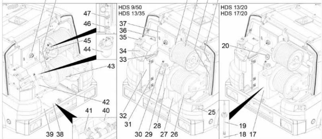
1H3eNoB DnBraTeN
②МeжdnHnHa npedabka
③ Nopma 3a BncoKo Hnrahe
④претанбнokногоркata
⑤Ayncnyx
6 N3paBHTeHcBbBOa 3a oxnaxdahe Ha DBNrataTJI
⑦ OTBOP 3a noDpBkKa Ha BOHnpe3epBOap (OTNBA)
Bb3nyweHΦnTbp
9TInoba TaBeIka
10Batepe
(1)Ne ha wacito
12 Komnpecop h a ropejikata
③TopuBHa TomnA
(4)ПpoToeH HarpeBaTeN
(5) TpaHcfoopMaTOp BnCOKo HAnpeXeHne
16 OTBOP3aNOdPbXkaHaBOHnpe3epBoap (OTJACHO)
17 Pe3epBoaap 3a nouchTbau npenapat
18 NocCTBaHnHaΦnIbpaHaBCMyKBaunmApKy 3aNoCHTaBn npenapat
19BCmykateenH mapky 3a noHCtBaun npenapat C DaTHK 3a HNBO
20 DOnpaaBENTn3a NOuHCTBaA npenapat
MRCTO3a npHaIeXHOCn 3a NcTOnET 3a pBHO npbckaHe
Macto3a npHnAdneXHoCTNa Tpb6a 3pa3npbckBaHe
23 Mapkyu 3a pa6ota noB BncoKo Hanrahe
24)Bapa6aH 3a Mapkya 3a pa6oTa noD Bucoko HanaRaHe
25 PpeKcbBa 3a aBapnHIO nKIOuBaHe
26Bapa6aHa MaPkyuHaNcKo HnraHe
27 Pe3epBOap 3a TeueH OMEKOTnTeI
28 Pe3epBoap 3a npenapat 3a 3auNTa OT 3ampb3BaHe
29 TbpnoBnHa 3a nIhHepeepBoap 3a rOpBOc ueka
30 CfepeueH Kpaan 3aunTa oT 3ampb3BaHe
31) INHnkaTop 3a HNBOTo pe3epBoap 3a BOda
32 Pe3epBoap c nonnabbk
33 Perynipane Ha oboopntte
OTBOP3a nIbHHepe3epBOap c nonnabbk c nOKpTNHe/kpHTHat 60NT
35 OTBOP 3a nBnHe He 3a TeueH OMeKOTHTeI
36 CfepeHnKpa 3a npBkIIOVAHe 3a BpBlaHe
37]TnabHO TaBNO
38 TpknBaua namapnHa (OTdACHO)
39 TOKPBAaJnamapHna (OTNBA)
40 Kpan 3a noDaahe Ha pe3epBoapa 3a Boda
(4)Изгуckатенин кран
42 Mapky 3a npenapaT 3a 3aunTa OT 3ampb3BaHe
43 Mapkya 3a Boda
(4) ΦπιTp b 3a BXODIa BOIa
(45)MaHOMEtBp
46 BxodnTOK3aunTnApOtnB3AmPb3BaHe CbOTB. no3mua 3a napKpIaPe 3a INBOD BUCOKo HAnrAhe GEKA
47 3xodmaNTOK3aunTaOT3ampt3Bahepecn. NO3mua 3a napkupahe 3a INBOD BICOKO Hnrahe
(48) Kanayka Ha pe3epBoapa
49 Panaen 3a obcnykbahe
Pahen 3a o6cnykBaHe
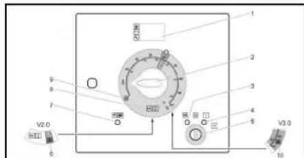
0/OFF=13Kn.
1Dinne
② PnpeKbCbaHаурEDA
③ KOthpOHa lamma PoiDrpBaHe (HepBena)
④ KOHTPONHa JAMMa FOToBHOCT 3a EKCNIOaTaUra (HepBeHa)
⑤KnIOyOB npekbcBaY
6 Pexim Ha pabota, ype 3a otctpaHbahe Ha nneBn V2.0 (onuHOHaHo npn HDS 13/20, HDS 17/20)
⑦ KOHTpOHaJaMaHaIpeDeH Kanak/abapnHO m3KlIOVABe(uepeha)
PekmHa pa6oTa CtyeHa/ToTnBa B0a (0-100°C)
PexmHa pa6ota 3aunTa ot 3ampb3BaHe
10 PexMM Ha pa6Ota, ype3a oTcTpaHraBaHe Ha npeBEn V3.0&V5.0cbTo. pexMM Ha pa6Ota c npapa (OnpmonHa np HDS 13/20, HDS 17/20)
Dokymentn 3a Oo6peHne
DOKyMeHTNE 3a OdoBpeHne 3a ypeDa ce cIbXpaHraBAT B WkaFa 3a eKeTprHeckypeH. IkaΦbTe 3akIOueH 3a TpaHcnpOtnpAheTO.
DucnnHopMaenpeXmHa pa6oTa
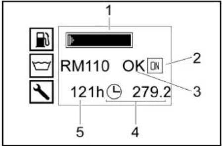
① Pe3epboaop 3a ronpBO (HNTOBA uHnDnkaun)
②ДиагтелВкн(ON)pecn.ДиагтелИЗКн(OFF)
3 Pe3epBoap 3a TeueH OMeKoTInTe RMI10/ pe3epBoap 3a noHCTBaU npenapat CHEM (OK/ npa3EH)
④БpoaHapa6oTHTeyacOBe
5 Pa6oTHn YacOBe Do cneBaaun CepBn3
Yka3aHue
Hdukaaama Ha pe3eepoapa 3a noucmeaowomo cpedcmeo e hanyu camo, aok npdu moea pe3eepoapb m 3n oocmeaowomo cpedcmeo eee e bu panaosham kamo nne
Ppu Hopmanha ekcnnoaunu duonneem Ha ynpaaenenuo nokazba nocnedobamnho cndhum uohukauu:
Hopmanepkum
Cepu3: Heo6xodmu pa6omu no n0opbkkama om cepu3a (bukme puku u noopbkka). Ako ca Heo6xodmu hKoNko pa6omu no np0pbkkama, me ce nokaam eHa cneD dpya. Ako He npedcmoam cpookoe 3n o0dpbkka, mazu uohukua omnda.
HeunpaeHocm:Haembuna HeunpaeHocm (awkme Pnou npu HeunpaeHocmu). Ako ca HanuHu HrkOko noepdu, me ce nokaseam eda ced ppya. Ako hma HanuHu noepdu, m3u uHukau omnda.
Dncnne,3aunTa npOTNB 3aMpb3BaHe
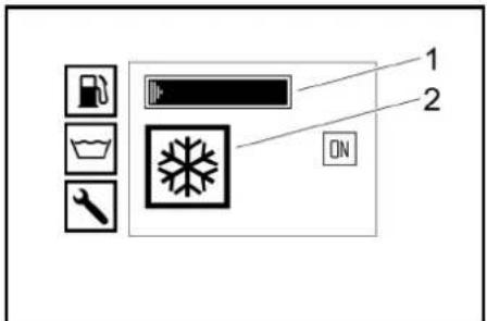
1 Pe3epBoap 3a roHBO (NeHToBA HNIMKaunr)
② Pexim Ha pa60ta 3aunTa ot 3ampb3BaHe
Iuctolet 3a pa60ta noB Bucoko Hanrahe
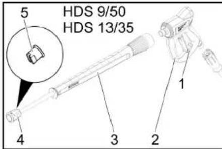
1Pepna3eH3aBbaMexAH3bMaHaNCTOJeta3a pa6otaNOBVCOKOHJrahe
②пстолетаразотаювсоканяганe
③ Tpb6a 3a pa3npbckBaHe
④XoIeHnpBaTraika
⑥ДIO3a 3a BnCOKHaHraHa
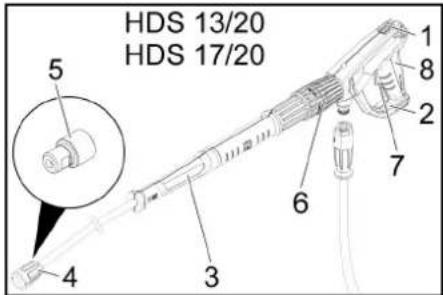
1Pepna3eH 3aIbBaM MEXAH3bM Ha NCTOJETa 3a pa6ota nD BnCOKHOHaRaHe
②Пистолетаразовая по Виско налгаге EASY!Force
③ Tpb6a 3a pa3npbckBahe EASYLock
(4) CbeDHHTeHaraKaEASYLock
⑤ДIO3a 3a BWCOKO HANRAH
6 Perynipane Ha HanraheTo/KonHeCTBOTo Ha nCTOneta 3a paOta NoD BnCOKO Hanrahe
⑦Ппесдаэнnot
(8) NocTHa cnycbKa
OTbapnHe/3aTbapnHe Ha nppeHnKaNAK
1.3aeneCTBaIe 3aknOuBaHTo Ha KaNaka. PpeDnHT KAnA Ke OTBapr IeKo.
2.Дe6nokpaTte 3axBaTHnte Kynupe3 n3dbpnaHe.
Pn3aTbapheYeBepe,eykata 3a 3axBauahe e3actonopeHa.
BnraTeN
- PpOBepeBaIe Bb3dyWnHnФnTTbp
- Pn Heo6xOaHMOCT NoHCTe/CMeHETe B3dyuHnHa FNTbp. (Bk. Pnxa Na NpDlbPkaHe)
HaJIbAHe Ha TeUeH OMEKOTnTeJ
TeuHnT OMeKoTnEIN PpeOToBpaTbRA epeKTnBHO o6p3aYBaHTo HA BApOBVK HA HArpeBaTeHnata cepNEHTnHa np paOta C BApOBtA BoDa OT BOOnpOBoDA. Ta Ce DoabRa HA KaKN Ha BXoDa Ha peeepBoaPa c nonnaBk.
- D03npoBkata e fa6pnHNo HacTpoEHa 3a cpeHa TBbpOCT HA BOaTa.
YkasaHue
B komnkema ha doomkaema e kmoeha e hna npo6ha onakoake meuen omekornmuen.
OTBOPETe OTBOPa 3a IIJIHEHe 3a TeEHOMEKOTHTEN.
2. DOneHTe TeueH OMeKoTHTeI.
3. 3aTbOpTe OTbopa 3a nBnHee 3a TeHeH OMEKOTHTEN.
DOnnBaHe Ha TOpNBO
ONACHOCT
Henodxoada o2opu8o
Onachocm om ekcnno3u
Hanaune camo duenseoo zopueo unu nek mazym. He mpbae ca ce uon3eam heodxodau zoupaa, kamo hap.6e3un.
yKa3aHue
Ppuynompe6a hau6o0u3en B5 (cbaancho EN 14214 -EeponeiCCKcmhaoPM) He e Heo6xOmo cnaeae Hn CnouuHn yocoeu Ha pa6oma,cepu3 u noopbkka.
Yka3aHue
Ppuynompeba ha buoouenB6 do B20 (cbanacno EN 14214-Eeponeicku cmahdapmcaheoxodu mu mepku3a npyepcmuocme ha duzenooeu deuaamen. Oceemmoa mpa6ea da sbdarn e3ema nod humane cneuaaunume ycooeu ha pa6oma, cepus u noopbka. Monobphe me kBM omopuzupah npdecmumen ha dmuMa Yanmar.
Yka3aHn3a3aunTa,6aTeepu
Ppna60ta c 6atepeHnTe HnpeMeHHo Cn3BaIte CneHNTE npdynpntENyka3AHN:

Cn3BaIte yka3AHNAHa BaTepyTA,B YnbTBAHETO 3a yNtpe6A M B NcHTpyKUNTA 3a EKnNoatauHa npeBb3HOTo CpeCTBO!

Hocete 3aunta 3a ouHTe!
DpbKte deuata hactpano ot KcennnHnNt o 8atatePnnt
OnachOCTOTekCNIO3N!

3a6paHraBaT ce OrBn, NCKPn, OTKpNTaCBETINHa n nyuhe!
OnachocT OT pa3Kdahe!

TbpbnOMOu!

Yka3aTeHa 3a6eJexKa!

OTcTpaHbAHe Ha oTnaDbun!

BaTePnraTa Ha He Ce XbBpNBA KOHeHepa 3a CMeT!
ONACHOCT
Onachocm om ekcnno3ur!
He noctmaaime uHcmpymeHmu unu noo6hu npedmemu ebyxkyakymamopa.Kbco cbeDuHue u onachomoc omekcnnoa.
△NPEDyNPEXDEHNE
Onachocm om ompaane!
HukoHa donyckaum KoHmakm Ha paHu c ono.
Cnepaobomama no akymyamopu bua
noucmeaume pbueme.
△NPEDYNPEXDEHNE
Onachocm om pa3xkahe!
Ppu pa6oma c kucenunama ha akymyamopa hoceme ycmouueu ha kucenuhu 3auumnu ouuna, pkaa uu npceumnka
3apekdaheHaakymyntopa
ONACHOCT
Onachocm om HapaHreahe!
Cnaseaune npaeunama 3a bezonaHocm npu paobomacakymamopu,kaKMO u uncmpyuaema 3a
ynompe6a, npdeocmaeaeho am npou3eodumena hyazapnoh ycmnpcmeo.
3apekdaumeakymyamopacamo cnooxoao 3apdno ycmpoucmgo.
- Pa3kaaye akymyaTopa.
2.CbpxkTe Ha NOnOxNtENHn NOIoc HA 3aprAHO TO yCTPOINCTBO CnBDOHa NIOJXNTENHn NOIoc HAkyMynATopa.
3.CbpxKeTe KaBena Ha OtpucaTeHNHa NIOHc Ha 3apAHOTO YCTPOINCTBO CnBDOHa OTPuCAteHNHa NIOHc Ha AkyMynATOpa. - ΠbXhETe ΦεπεCηa N BκΠΟΥΕte 3αρλΗΤΟΥCTΟθΟ
5.3apejdaite akymyntaopo cBb3MOKHOHnCn6nBuTOHKa3peJDahe
MOHTnpaHe Ha nHcToJeTa C BnCOKO HnlaRHaE, CTOMaHeHaT a Tp56a, DnO3aTu MApKyUc B NcKOHnlaRHaE
- Tpb6ata 3a pa3npbckBaHe da ce Cbpxe cnctoneta 3a pbHOp pa3npcbkBaHe.
- 3aterheHa pKa 3aBnHTBaHTo Ha Tpb6ata 3a pa3npbckBaHe.
- NocabeTe DIO3aTa 3a BnCOKo HAnraHe B xOJIeHDPobata rAka.
- MohtnpaTe n 3aTeHHeTe 3dApBo xOEnHpOBaTa raiKa.
5.CbpxeMe Mapkyuca BncoKoHaIraHe KbM nCTOneta C BncoKo HaIraHe.
BHIMAHNE
Pa60a c nooNCTBaun npenapatn
CaMo HDS 13/20, HDS 17/20
BHIMAHHE
Noepeda npadu henoxdoxa cpecdmea 3a noodpdxane
Henoxdoohu noocmeaun npenapmu Moam da nopebarm yepda u noocmeaunha o6ekm.
Hnnon3aeume camc pcdcmama 3a noobpkahe,
npedhahayehu 3a o6ekma.
I3nOJI3BaIeNCTeINIO NOCHTBAAUNI INPENAPATIN, 3aJaUaDIIte OKONHATA cpeA.
Cn3aBHTpe npenopbTuHNTa Do3npOBKa Iyka3aHnTAt, pInnoXeHN KbM NOUcTBauNTe npenapATN.
TpaBbJa da ce n3no3BaT cAmO nouchTaBauN npenapatn, KOtTO npOn3BODnteH Na ypeDa oOobpbA.
- POnCTBaunTe npenapaHa Karcher rapaHTnpaT 6e3npo6nemHa pa6ota. MoJI, KOChyTTnpaTe ce NN NONCKaTIte HaUNA KaTALOr IIN HAUNTE INHΦOPMaUHOHH JNCTOBE 3a NoCHTBAUNI npenapATi.
1. OkaHeTe BCMyKaTeHnMa MapKU 3a NoHCTBaU npenapat B pEe3epoBao C noCTBAU npenapat n 3aBnHTeTo DoIbe 3aBnHTBaUma CE KANAK.
2. HactpoTe Do3npaunBbHTn 3a NoHCTBaUn npenapat Ha JeNaHATA KOHcHTpaunr.
yKa3aHue
3a da npedopamume obpamhmo u3muuane Ha cpedcmeo 3a noucmbane B pezepeoapa c nonpaas k unu pezepeoapume 3a eoda npu eknnoamaua cbc cpedcmeo 3a noucmbane U 3amopeh pbuen pa3npbckamehen nucomen, dozupaunm knanan 3a cpedcmeo 3a noucmbane mprba de b6de 3aumoe.
OctpaHbAHe Ha nneBenn
CamaHDS13/20,HDS17/20(onu)
yka3aHue
3a ekcnnoamauha omcmpaHraeaHemo Ha nneenu e 3aobxumeho MOmaXHHm KOMnkekm 3a ynpaenhe Ha o6bopome (Onuca, fapbuHo: 2.013-086.7, komnkekm 3a dooo6pydeae: 2.013- 014.0! Ocbnyeae Hc bJAncho pkoBocmeo 3a ekcnnoamauha omcmpaHraeaHemo Ha nneenu WR 10, No ha caxm 5.968-256.0 cbome.WR 20/WR 50/WR 100, No Ha caxm 5.967-455.0!
Ocebn ToBa TpaBbA Da ce sbIIODaBa cneHnata HnFOMaMa:
- MoThIpaIaIe WR 10, 20, 50 nIIu 100 Ha TpIb6aTa3a paIaIpbckBaHene I noctabeTe NoXdoXuIaTaIaIO3a (Bk. CbOTBeTHOTo pKBOOCTBO 3a EKcNIOATAUJIa).
-
3abpTeTKeIIOOOBnpeKcBaB NOIOXeHHe "I". KOHTpONHATA nAMNa 3a rTOBOHOC 3a ekNIOaTaun CBeTb. YnpaBnRAuToH NaHEPoe He CE BkNOBa NDCnNErT NOKa3Ba pa6oTHoTcBCTOHe.
-
Hatimchefte nocta 3a ynpablenhe Ha o60pOITE Dokpa HADONY.
Ype3aOTCTpaHbAheHa nJIeBENV2.0
- Hactpoite npeBknOuBaTeHa ypeHa ha pexM Ha pa6oTa,OTCTpaHraBaHa nnEbeN V2.0".
- 3aBpTete KIOUOBIN PpeKbCBAH, DOKATO DBWATENT NOTERNI.
3.Ocbo6oTe NIOCTOEnTa 3a paObTa nOd BnCOKo HnAraHa,3a ZeTtA HnCTe HaNCTe Ha3ad PnpEJa3HnA 3aIbBaU MEXAHm3bM. - O'TbOpete nictoTeta 3a paBota noD BnCOKO hAnJaHae,
Ha dncnner ce noka3Ba TEMP LOW:OTHEMA OKOIO 2-4 MHyTn,doKato ce doCTHHe pa60THATA TEMNEpTaYa.
3aHTa OT 3ampb3BaHe Ha akymyIaTopa
1.Ako HAKOJIKO CeMmUHn HA Ma Da ce paobTu cypea nopaN CINHO 3AmPb3BaHe, DEMONTuPaIte aKymyIaTopa Iro CBxpaHraBte Ha 3auiTeHO t O 3AmPb3BaHe MRCTO.
PpOMBaHe c npenapaT3a3aunTaOT 3aMpb3BaHe Bzpkynpau Kpbr (nomna 3a BncoKnHaIraHe)
1.PnBbHuHO 3axpaHae C BOda:OTDepe
2. Nocabete npekcbcaha na ypeda ha "O/OFF" (Fopelka mkn).
3. Ocbo6oTe ypea ot haJraHeto.
4. Noctabete npkcbcaha na ypeda na pekHM nap60ta 3aunita oT 3ampb3aHa
5. Camo HDS 13/20, HDS 17/20: NocTaBete
dorpaunna knanah 3a noNCTBaau npenapat Ha
MaKcMym. INterne BCMyKaTeHnHa Mapky 3a
noNCTbaau npenapat ot pe3epBoapa 3a
NoNCTBaau npenapat Iro nOIOxKeT TaKa, Ye da
MOke da 6bde n3npa3HeH.
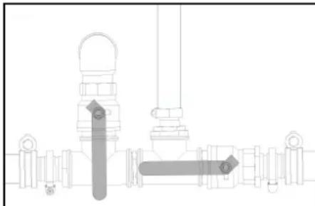
- OToBopTe KpHa 3a NoIaBaHae Na pEeepBoaap 3a BOda H KpaHa 3a N3TOUBaHe, 3a Da N3PnPa3HnTe N3JNo YpeDa.
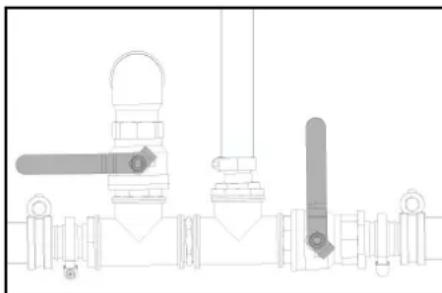
HnMkatoptB3a HNBOTOHa pe3epBoapa 3a BOda cnada nauyo.
- 3aTbOpete KpHa 3a IpoIabae Ha pe3epBoapa 3a BOJa I KpaHa 3a IN3TO4BaE.
- OTeJETe NtCTOnTe a CBnCOKo HaNrAHe OT MapkyuCA BnCOKO HaNrAHe.
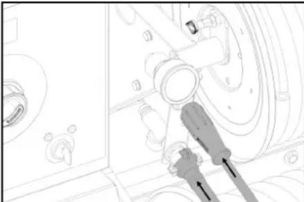
9.CbPkETeMAPKya 3a BnCOKO HAIJRAHKe KMb NOPADABHeHO 3aUHTAOT AEAMp3BaHe
10.CbPdKTeMAPkyBa 3aOda KbM H3XoJaIuNnIOToKHa 3au3TATAOT 3aMBy3BaHe.
11. NocTABeTe TeyHOCCTTa 3a 3auITa OT a3amPb3BaHe bpe3epBoapa 3a npnapat 3a 3auNTa OT 3amPb3BaHe. H36BePeTe CbTOHouEnTo Ha cMecBaHe B0a/3auNTa npOTVB 3amPb3BaHe cNopeD daHHnTE Ha npOu3BOmTeIeHa npenapat 3a 3auNTa OT a3amPb3BaHe.
12. PpOBepe ToKoHcHTpaunraHa npenapata 3a 3aUHTa OT 3AmPb3BaHe C KOHeBHeNIOHaHE TecTe p 3a3auNTa IpoTINB 3AmPb3BaHe N pN Heo6XoDMOC7 aJaTnTPAIte.

BuHau cMeHJUme noepedeHume KluHoEpupeMbU. Cma3BaHe Ha aBToMaTHuHaTcNpaKa
- OT DBATA CMA300HH HINENA C KOHBEHUNOHAHNA peca 3a rpecupane N3CTNCKaTe cBtBTHTata rpec.
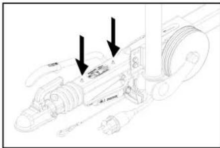
1Cma3oueH HmneI
IpoBepka Ha HanaRaHeTo Ha rymnte
- Cnpete ypeda Ha paBHa nobbpxHocT.
2.CbPkTe MaHometbpa 3a npOBepka Ha Bb3DyHOTo HAnraHe Ha rMITE KbM BEHTnla Ha rMYNTe. - Побerte Бьдуното Hanrahe(ВК.TexHueckn DaHHN)и рп Heo6xOmocr roKopnrpnte.
CmHaHa ryma
△ONACHOCT
Onachocm 3a kuboma npadu Henpekbchamdozuxheue
Pocmaaune yepda na haena noebpxhcu h oeceme obnekno c eucoka eudumocm, kazo amu3epuame pemohnu deuohcnu ha ocmeeehu nbmuia.
- NocTabete ypea Bbpxy paBHa nobBpXHOCT.
- PnOBepeTe yToHmUBOCTHa OCHOBATA. DOnbHnTENHO OcNpyeypea Cpeu CaONPO3B0IHO PNINBIXBAHe CnoJIOKeHN KINH
3.БлokираиTe 3aCToNopRbAaUaTaNpuraKa. - PpOBepTe rMnTe.
- Xoobaba nOBpbXHOCT Ha rymite Da ce npoeber3a pOHHHn PnpDMETN.
- Da ce otctpaHr npeDMrTe.
- Да мионлов наохюдши ремонтни срдоства 3a Удип оТь探测бда моржа.
yKa3aHue
Ja ce cna3am npenopbKume Ha cbomeemHua npou3aodumen. B3moxho e npobnkaeahe Ha nbmyaehmo npu cna3aeHa daHume Ha npou3aodumenHa npodykma. Konkomo e b3moxho no-coko da ue3bpuw CMHA ha yumume pcn. CMHA KAonema.
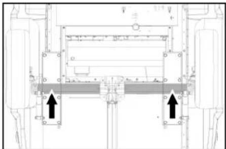
8. NOCTABETE ABOTOMOIBNHHK PKN HA CLOTBTBHTO MRCTO 3A NOCTABHIE.
-
Pa3xaabeTe KOJeeCHHTe 6oNTOBe.
-
NOBUNHETe ypeDa c aBtOMoBnHnKpaH.
- Pa3BnTe KOJEnCHTe 6oJTOBe.
- CbaTe rymata.
13.Да ce noctabn pe3epBHOTo KOneJo. - NocTaBeTe KoneChHrE BoNToBe.
15.CnycheTe ypeDa c aBTOMObUNHnKpaH.
16.3aterheTe KOJecHte 6oTObe Ha KpbCT.
HD 9/23 GeTr1 + HD 9/23 DeTr1
N3MepeHo:105
TapaANTnpaHo:107
HDS 13/20 DeTr1
N3MepeHo:97
TapaHTnpaHo:100
HDS 13/35 DeTr1 + HDS 9/50 DeTr1
U3MepeHo:100
TapaANTpaHo: 102
HDS 17/20 DeTr1
U3MepeHo:100
TapaANTnpaHo:102
OPTIONAL
Ipoodyt: ABS Dampf HDS 1000
Tun: 2.013-093.0
KateropnHaMoDyHa
1
IpoueDpya 3a oueHBAhe Ha cboTBeTcTBHeTo
Modyn H1
HarpeBaTeHa cepneHTnHa
OueHka Ha cbotbETCTBneTo, MOnyH H1
UnpablaBau6nok
OueHka Ha cboTBeTcTBnETo, Moyn H1
Pa3nHn Tpb6oPbOBoN
OueHka Ha cboTBcTcBmETo, YneH 4,naparpa3
PpHnOxKeH CneuNfKaunn:
AD 2000 BB3 OCHOBA Ha
TRD 801 Bb3 OCHOBa Ha
ImeHaHotnPhiupaHnOpraH:
2014/68/EC

F.Jenner Chairman of the Board of Management
S. Reiser
Manager Regulatory Affairs & Certification
TbHOMOuHK No DOKyMeHTaUNrTa:
S. Reiser
Alfred Kärcher SE & Co. KG
Alfred-Karcher-Str.28-40
71364 Winnenden (Germany)
Ten.: +49 7195 14-0
ΦaKc: +49 7195 14-2212
BunHeHdEn,2023/01/01
TexHnueckn daHHN
Akaynap Ke3iHderi KEMek 399
Keninik 402
Kypan-ka6bI Kapm MeH KocAnBb 6eWekTeP.... 402
EO cTaNapTTapbHa caiKeCTiri Typanbl
Deknapaun 402
TexHnKaIbIK MaFMyMaTTap. 402
Xannbln Hcyckaynap


KpybIbHbI anraa naJanaanBac 6byh, ocbI TynHcyka HcaykayltbTb OKbn, onoBbIHHa apeket etH3Jx
KeHHiPeK nainananyuHHeMece KeNeci neeneruyuHcKaTaN KoHbH3.
TacImaay Ke3iHe 3aKbIMdAnrH JxafJaIa depey Dnepre XabapnBh.
Kopanwa iuiHne 6onrah Kpapan-6enwekeptinH TyreDINH KopanwahbHa uWkA yaKbTTa TEKcepin anBbH.
Anraaw pet naanahyra 6epyden 6pybH, No 5.951-949.0KayincdikxkeHHenHcaynbKneH TaHbCnMbHbH3:
KopshaHaOpTaHbI Kopray

OpaybI MatepnaIapnbytynn3aunnyFa 60ana. OpaybIuparbKnopuaan optara Kayinci3 Tpye nynnn3auuunHba.

3NeKtpNk XHHe 3JKeTPOhD K6YHMdapbH KypaMbHda Ka Ke TOnHy MeMece YTNNAaUyay HnXeCiHde aadm
DeHcaybIfbHa XHe KOpUarAH optara Kayin TEHpyI bKtMaj, KyHbI KaTaN eHdEnMei MATEpMaJapXe6Batapeapn, AkkymyTApTopnap HEMec MEa CNKHTb6enweKTe KxI Ke3deCedl. AnJaDa, aTaAMMbI 6eJIWeKTe 6yIbMbI TnicHne naIanaHny yuih KaKet BonAbl. Ocb TaHbAmeh 6BelrInHRe H KypBfBnAPDbY KOKbCTapBImE Bipre Tactaya 60nMaJb.
Kypamdaftb3aTap6oHbHnHaHyckaynap (REACH)
BbIMMHbN KypamBnDaBt 3attap Tpyanb CoHbMennMeHa MeKeHKa6oBuHaTabyRa6baNa: www.kaercher.de/REACH
Kopwarh opTaHbI Kopray 6oBHHa KocbIMwa aKnapaT
MOTOP MAJIb, KJIbIbI TY MAJIb, DIN3eNb MEH 6EHNHHI H KOPJAHAR optara TycyIHe KOJIepMeH3. TOnbpaKTI KOPFaHb3 XKe He naJaIaHaBILrA H MaJIb I KOpJAHAR optara TnIcHb3 Type KeDere KApaTbHb3.
KypbInfBidaFbTaH6anap

KorapbTereypHidi arbIcbl aadamdpra, Kahyapnapra, KymbcICTen Typhah 0eKtpkn KpbunfBra XaKe KpbunBnHbH 03He6GarblTayra TbMmCanbHab. KpblFbHbHa3dAh KopFaHb3.

3NeKtp KepHeyiHc THeTin Kayin. 3NeKtp KOHbIprblnapblHdabbl kMybIctapbl Tek biNtki 3NeKtpkTep Hemece yakiNETTI mAmHaDap kypri3e anaabi.

Kbcbny Kayni Typanbi eckeprijia!

Kopy xhe octy kabineTINH 3akbmdany kayni.Ke3di xhe octy kabineTINKopray Kpyanb HkiH3.

Ybna naanahbnra raadap cannapnAH nceaynbka kayin. NaananaHnra ra36ben dem anlmh3.
blctbik bettepin ocepiHen kyin kany kayni 6ap.
MaKcaTbHa cEiKeC KOnDaHy
HycKay
Tek Tepmaunura kambcmi: KpybIbnr mek MoBuBoi (mcauonapbki eme) naidanahyra aphanra.
KpybIbHbI 3NEKTP KcBbIMbMbIXoKXHe bCTbIK cybn naanana hy KaKET 6onf Hkaaada apHaBk KOndaHabd.
Taaanay:MaunHnapdb,KeikTepdi, KypbInbIMapdb,KypandaPdb,Kac6eTepdi, TeppaccanapdbXane 6aKaWAsKypandapBnXane T.6.
KAYIN
Kapakam any kayni 6ap!
JHakapmau kyo cmaunnapnla hemece baca Kaayimti kejnpede naaandya nekihde
Tuicmi kayinci3ik epexeepin cakmaHB3.
Mnhepani xHaHApMaKocbIraH KAndbk Cydbx Jepre, cy aBIMdpbHa HEmece KaHAN3aJnra KYIMaHb3. KoFANTkBtW yxy HEmece MaHINanapDb acTbHAn HxyBH TEK kHaXaHApMaDbipiKeTe anAaTbH KyNecc 6ap naBkTbXeepnepe dTK3H3.
Cymen Xa6bikTayra apHanraH weKTI MOnHep
HA3AP AYdAPbIHbl
JaacmaHrah cy
KypbIrfiAbfI Mep3IMHeH BcyBH mOy HemeCe WzaiHineP
KypbIbIbIbIwekmeynepeh acnaumib masa cymeHemece kauma eHDozeneH cymeHa KaMaMaCb3 emiH3.
CymenXabkTayfKeNeci WeKTI MAndep KOnDaHbInaDbI:
| ph māhi | 6,5-9,5 |
| Электр ᵇткίзιτιrì | Туць сydьн ᵄткίзιτιrì + 1200 мкС/сm |
| Тундьг本科生 3аΤΑР** | < 0,5 Mr/π |
| Суztейпн 3аΤΑР*** | < 50 Mr/π |
| Кемиртуктор | < 20 Mr/π |
| Хлорд | < 300 Mr/π |
| Сульфат | < 240 Mr/π |
| Калци | < 200 Mr/π |
| Жалны кермektik | < 28 °dH < 50 °TH < 500 ровимлpe (мг CaCO3/n) |
| Temip | < 0,5 Mr/π |
| Марраец | < 0,05 Mr/π |
| Мыс | < 2 Mr/π |
| Бени缄д iхлор | < 0,3 Mr/π |
| Жавыmbсьи зic жок | |
MaKcHmAnIbI XaJIbI 2000 MkC/cm ** CbIHAMA KeNEMI I n, TnDbIpy YaKbITb 30 MNH ** ABpa3nBti 3aTTAP KOK
KayinciDik HycKayIapbl
KAYIN
KypbHbHbJka6bIKjepde naaHaHaHaHb3.
Dunbok omblbobyawkbomtmbn HeMece neuimep, kazahdbinmap,cykbubmkbuimapxhe m.6.wamby 6ap HeMece yukhbin wibarpambih KpybnfbanapbH xhaHbda cakmmai, mekneH3 HeMece naaanaanbaHs.
KaHApMaBaaBHewkaWahwamadahmbc mOJIbIPMaHbI3.
KannblaaknapaT
CvBik AfbHbipbHa KaTbCTb Tnicti YTTbIK HOpMaIapDbCaKaTaHb3.
KpybIbHbI KpOaHaHbHbIa OcbI ene KyuTe 60fAn aattapdb BonDbIpy TaPnbl epexenei MeH aHaDpaHbA ceKeEpeK eTtHJc. CyBHKabHApdpy HEmi Taekepin TyPy KepeKxHe CbHaK hTaNkepepi Ka36aMa TyPe Jka3bIyBk KepeK.
KpybblbHxblbTy KpybIbCblKaHy KOblprbc60bnTabnaOblTmictyTTbck epexenepe caincK yHMe Tkecpin TybH3.
By pexminin6kityxiharbl6ap KpybInbnapra rana kondaHnnaDb. KondaHbctaB1 yTTtbK epekenepe caNec, 6y0Korpa bkbimdb kyybuih TOMMEPAHnMakcatta naDnAnaHaR Ke3e 6ipini pet 6iniKT aam icke Kocby Kepek. KARCHER 6yn 6actanbna nndanaHy db icke Kocdy c13 yuH opbHdAn, KKaT 6oBuHua pacimden KoiHan. Tmict KkytaTAMahb Cypay 6oHnHa KARCHER cepiTeCIN3en ana anacb. Kykattama KaTbCTb CypaKTapbHb3 60Jca,
KyIbIbIbHbIbIbIbIbIbIbIbIbIbIbIbIbIbIbIbIbIbIbIbIbIbIbIbIbIbIbIbIbIbIbIbIbIbIbIbIbIbIbIbIbIbIbIbIbIbIbIbIbIbIb
By pexmminb6kity knaHab6ap KpyblnIbnapra rha KondaHbIaBb. KondaHbCTaBfYyTTbIK epexenepre caNkec Kpyblnbbl 6iikTI aam yhem Tekepin otbypbi Kepek eekhInhEeckepH3. KARCHER cepikteciH3re xaabpaacbHb3.
Cis KpybIyfRa JxHe KepeK-KapKaTApra 03repTepeHri6eyiH3KepeK.
DhenreIek Kypcaaybl
KAYIN
Xa3amaubim Okura kayni
UHAnap JxorapbI KblnDAmBkMa 6ocan KaYbyMMyKIn.
100 KM/car pykcam eminaen Keikmep yuih: uuHana p an ambi kxbindan acnayb kepe. Byiip Kaibpracbnda 3aikim, oukbmap/kapbikmap, npomekmopbih 6eniHynepi KHe m.6 Gonca, uuuHanaPbMe apaada aybcbipykepe.
XorapbI tereypinki Ky6bpwek
KAYIN
Kapakamanykayni6ap!
TynHcyKa Kofapb Kbcmbdu JnaHTepdFa HanaDnAnhBuH3.
KorapbTereypinDi K6bpueKneB6pykkiu KypblfBXTNHKnBk DepeKTepDe KepeTINrE MAKcMaIaBbXMyBcKbCbMbHa CaiKec 60nyb KepeK.
XIMNAbIK 3aTTapFa TIN KeTydeH caK 60JIbIHbI3.
KyncaibnXorapbTereypinIkybipwektTekepin OtbpbHb3.MaibickanWnaHrtapdb naananahaBc. CbiptkcbmKa6abTKePIN Tpyca, XorapbTereypinIkybipwekt naananahaBc3.
BypaHa 3aKbIMdaFAn 60nca, XoFapbTeReepinDkybipweKTI naDaanHbHb3.
Korapb terepyHdi Kybpaewkt yctiHene KoarmaMauBthdAe tEIN OPhatBtBh3.
EkaHdaa3akbIMKeip16ce de,Ke3aIyA,MaiIcBIn Kany HeMeCE cory Ke3IHe 3aKbIMdAnfAH JnAHTbI naJanaHaBb3.
KofapbI TereyipHIni KbiUpEeKT MExaHPKaBk Ecep 60mImuTbnHd erin caKaTHbJ.
ФУнкун
KorapbI KbcbIMBoCpBfNIOEBMOTOpBmEH apabIKkETEKApkbIbKO3fanaDb.
KANTkai Kamepa MeH XorapbI KbCmblc copBf apacihdafl Ko3rTKBtBuH CaNkHbHaTKBu CYbIKbTaI aHnAIBMbID opHanaackaH kJyIy ANMactpBfhu APkJIbXkbJIbTuJaIa.
Copranaay kymbctapby yaiin kanaHaJa, kaTataKTHAYaHbIKbMbCh3 cy aHaNbIMbHa ayBaCaDaJxHe KOzFaTkbIbOc aHaNbMa dyaXMyCbBih XaJIrFactbPaDb.
Cy KbIbMbIpbAbKbIbYMbIcICTeITH MaJIbXHaAPBbIMeKbIbDbPbJbAa.
blcymHBMxMbicictereHeCyraCybIKYMCCAPKtBkIOKCbJlAnb.
TeK HDS 9/50, HDS 13/35 (HDS 13/20, HDS 17/20 yuHH KocbIMua): KyMbIC KbCbMBH KO3FaNTKbl WbldAmdbfbh backapy KpypAlb apkblb TaHdayra gonably.
TekHDS13/20HDS17/20:Korapbkbcbmdb copby Kyyblkpandpb copbn anaDb. Cydarby Kyyblkpandbh yncie Hmneepney KnanaHBHH Kemerimeh pettey 6oanda.
TekHDS13/20,HDS17/20(KocbImaa):bctbK cymen apamuenterpi KOHora aphanrah6eKITy XnHArf.
TekHDS13/20,HDS17/20(KocbIMma):6ymen Ta7anayxaneHepnFeknayuyuH6KITy XnHaBbl.
KopraHbIC KypaI-ja6DbIKTapbl
Koprahbc Kypan-Xa6bIbKTapb naDanahybHbKopfay yuHn KblMeT etdi Jxhe onapdb Eupyre Hemece onapdbn FyHKnRcBn aiHaBn Etyre 60maMa.
Keen eipriu
BapnbKdyHKnnaIapdbIpepey Tokrty yuH: XeDen eipriiw 6acbiH3.
AndbHrbxankbIHTbIH Kayinci3dk Kockblwbl
KyblbIbHbIaIbIbIbIxIaXnbIbIxIaXbIbIraHKe3deRaHa naIadanahrya 60bnai.
Kymbc Ke3Hpe andbHfbfkaanbIaBbH 60nca, KpybnEweJxhe anbHf bXankbHbHAnATbIKewpyDin BakInay Wambl KblbnGonbln XanaHb
KaTAtkki3yKnanaHbI
KoB6pykkiu nIcTOnet XabInca, KaTAtEkn3y KnaanbA uBbIaNblXHe Xofapbl KbcMbIb copfbl cybl kaTadaH KanKbKaMepacbHa XiBepeNi. By yKcat etinreH XMyBlc KbCbMbIH apTybHa kon 6epMeidl.
TeK HDs 13/20, HDs 17/20: kon6ypiKkU WnCToTETeri KbCmBdMl/MenWepD pTeTey apKbUbI cyDbH KENEMIH a3aNtKaHda,KaTaNTk3Y kNaAHa bauBaIaBbI KHe cyDbH 6ip 6eNirI KaNTkb KAMEpAcbHa HEmecce cy BaKTapHa KaTa arAdy (wAp KpaHbHbH KaTapy aRbHbHbH aKbPaTbKluHbH OPbHa BaaJaHaCbTb).
KaIa eKl3y knanahb 3aybTTa opHaTbIn, TbIfb3dAnfA.HcIbnabH opHaTbNby TEK KaHa KpybIbY wih TybHyBnapRa KblMet Kepcety MAMHApB apkBnE tK3iiny TLic.
Kayincizik knanahbI
Kaita eti3y knaanbH meHecme KbiMbKocBbIbH ayaknbl Bonca, Kayiciadikl knaanbH aubnabH.
Kayincikl klanahbl 3aayta ophahtbn, Tbfbldanran. Teueydi Ke tybHybnapra Konday kepcety KbiMeT opbHdna
BatapeHbI 3apTay torbH 6aKbIay XyHei
BatapehHb3apraTKe3HHeJxapbKaTHdbpyFa apHaTrH reHepaTOpBbH 3apraTay TOrbI xetKInKiCi6oNc,KyPbNlEwei.
DucnneDi erakay:KATE1
Cy kipiciHH Hemece caKbHdaTkbIu cydbH TemnepaTypacbIH 6akbnay xyneci
Cydblkipc Temnepatypacbypykcat etinreH eh Xorapbl Temnepatypaah acbinketce, KpybIeBf eewdi.
CanbHdaTbIcCy TemnepatypacbIpyKcTetInreH enKorapbTeMnpaTypaHaHacBtKeTc,Kpbrfbe ewei.
Ducnneiay:KATE3
Cy tanwbnbfbihn KopraaTbH KaNTkbi KaMepa
Cy TaTbnBnBfHAn HcPoyjXyHeC cy JyEticenereHDe CzraTaNbHTbKocyra xon 6epMei.
DucnneDi eriakay:KATE4
Cy TanubibfbihKopraTbH KaHaPfbl
CyTanaBnBbHAnKopraTbHKnpyBt(arBn KocBbB)KaHaPbBbHWeKeTHbIcBk3BnKeTyHeKoepMeiKaHaPbBcMy6BeyKeTKinKiBoFHaRa HyaKymbcIeTeb6aTaAaB.
Ducnnei deri ay: KATE 5
Kbcim Kockbllb/afbih Kockblwbl
KbIcIM KockbHbIa/AFBbH KOCkbHbIb KOMNHaINrCbCy TaunbHbIbFbHEmece aFBn KETy XaFdaNbHDa KpybIbFbHbEwepJe.
DucnneIerikay:KATE5
XaHapMaI DeHreInH 6akblay
KaHApMaJ KETICNEHTIH 60nCa (KaHApMaJ 6aBb 6oc),KpyIbnfbl eWesi.
HycKay
Kypblbfbki Kocy xhe eippy apkbln on xahapmau 6aabi monlbfimbocarabhaip yakimma5 Muhym xmybcbihxanfarmbpa anaabi.
KaHaMaJ DaTnHrI kaaynb60nca, KpybNf b eWdi. Dncnneeri kaiy:KATE 6
Ko3fantKbIu MaBbl
KbIcIM KOCBIIBKO3FaNTKBIIMaBHbH EHTMeHH KblcIMHaH acBIn KEtKeHDe KO3FaNTKBIITbEwipei.
- Dnncnnei deri akay: KATE 7
PnDnAnhbnfHra3 TemnepaypacbH weKTERi
- PnndanaHbIraf ra3 TemnepaTypacbI TbIM XcFapbl60na, na, nndanaHbIraf ra3 TemnpaTypacbIHweKTERIW xHaAPBbHbEwipdi
DncnneDi eray: KATE 9
TemnepaTpaHbI 6akblay XaHaPfbicbl
XHaHapBbIbIbCbIaDabcCydbH TemnepaTpyacb pyKcat etinre en Hxorapb TemnpatypadaH acbin KETCE, KBybIbIbXHaHapBbHIbEippei.
Tmemepatypa daunirakaybnb cncba kynnnb eeweii.
Dncnnei aay: KATE 10
KanbHdb6akbinay
XaJIbHbIb6KJbnayKaHaBcIbHnDaakaybl60FaHnKaJaTaDaaKaHaBcHbNbUeipJe.
Dncnneiay:KATE 11 Hemece 12
Kyty peXmH en acbIn KeTKeHHen Hemece 3ikci3 KymbictaKeiH eipy
Kyry pekmmHemece 45 MMHTbIK ydiKiCi3 KymbC yaBtHaH acbn KeTc, 3NeKTPOHnKa KpyblfHbI eWipeD (aybTTbIK napaMetP).
Dncnneiay:KATE14Hemece15
CaKaTaHDbipfbIiTetiri
Kon 6byikiiu nctoTeHderi cakTaHbApBtu Tetiri KpyblnBuHIn Ke3deEcoK TypeKeOcbIyBaHa Kon6BepMei.
KypbIFbIHbH cbiptkki Ken6eTI
KypbINfbHbIH CnnaTTaMaCbI
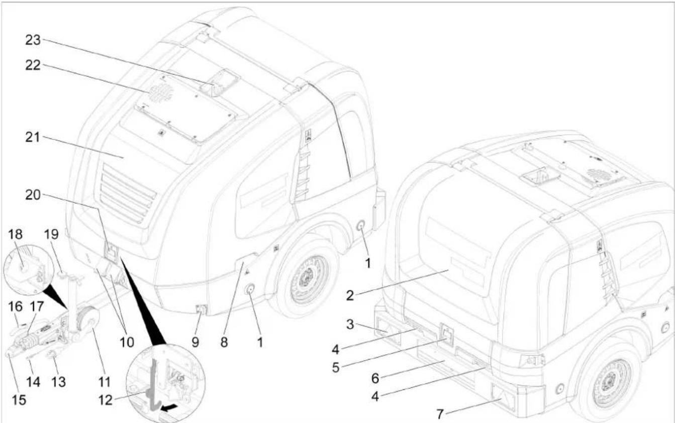
① PeΦneKTop (ekxar)
2AptKbI KAnkbll
③ Barap KepeTkiTepi 6apapanac TeKerIwapTkbl am (con kakTa)
4 ApTkbl kAnkbIbIy Ka6bIK Kynde JnaHr 6epy
⑤ ApTkbl KaaKbll Knynbl
⑥ Hemip wamapb6ap Hemip
7 Barap KepeTkiTepi 6apapanac TekeiWapTkbl WAM (OH JAKTA)
8AnbHrbXanKbW TyKacBHBnObnr (ekxar)
9Kelemmigiawamdap (ekjkaftb)
10 Cbipyra Kapcbi tipek
1) Tipektrik dhenrenek
12YCTaftbllIMMek
13 Kenikti kapbiktahdpatbH xanfafbi
14AxbipatbinaTbH Ka6enb
19 TapTkbiu
16 Typak texeriui
7MyTAtyTKacbl
18 KenikTI XapbIKTaHbIpaTbIH XaIrafbIbHdArbl TyTKa
19 TipeKtik dHreNeK ca6b
20 AndbHfbjXankbW Knynnb
②AndbHbI XaNkbIu
22 NaiDanaHbInra ra3apra apHanra ncaHbInay
23UIMek6ypan
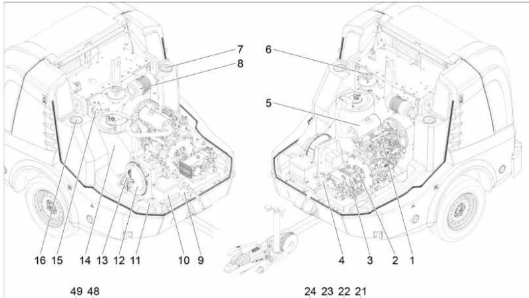
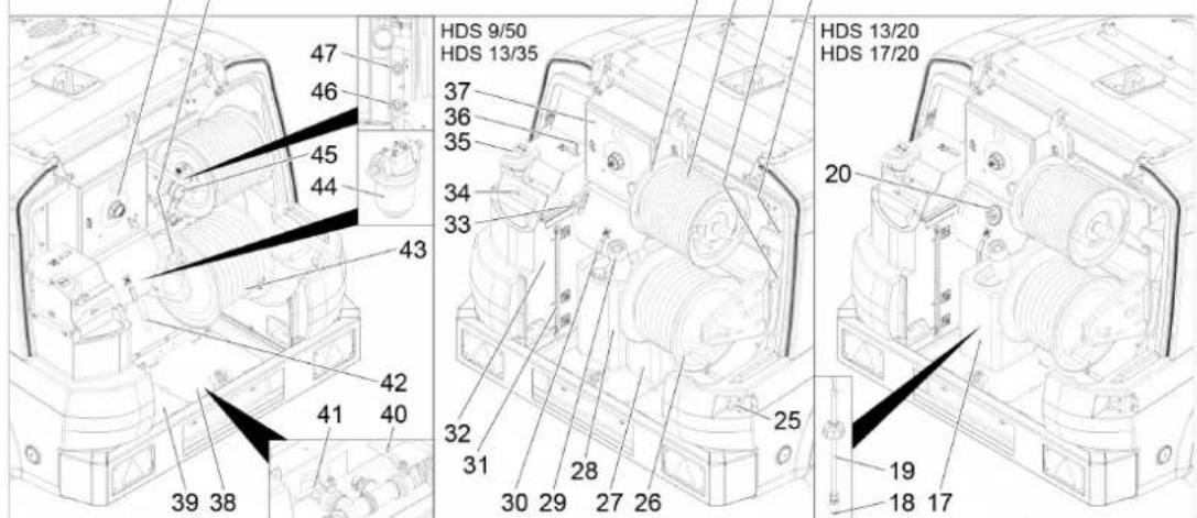
1M3eMbMOToPbI
(2)ApaJIbIK JKeTeK
③ KofapbkiKbIcbIMdbcopFbl
(4)KaHApfbHbHcakTaHdbipfbIb6Jorbl
(5)Copy
6 KozraTbIbTbH caKbIHdaTkbIcYbIKTbIFbIH THeCTpy bIdbcbl
⑦ Cy 6aBbHa TeXHnKaIbIK KbI3MeT KepeTy aUbInybl (con KaKta)
Aya cyarici
9Bayt TaKaTaiuacbi
10Баразяe
11JaccnHemipi
(2)KaHApFbI JeNJIeTKeiJIi
③KaHapMaip copfbcbi
(4)ArblHbI cykbIbITKbII
15 Kofapb KepHey TpaHcΦopMaTObp
6 Cy barhH TeHHKaJIbIK Kbl3MeT KepCey caHbIaay(b) (OH KaKTA)
7 KyrbH KypaIbH KOHei
18)Kyrbii Kypandbin cop ynaHricinderi cy3ri
19 DeHre Kepcetkiu6ap kYbIu KypaIbH copy
20 Ta3anay KypanbH Menweepney KnanaHb
21 Kon 6ypiKiuu nctonetti caKtayra apHaHraH 6eim
22) Afbic TYTirih cakTayfapa hahFaH 6enIM
(23)KorapbTereepiHkiKy6bpweK
24KofapblkbicmbdbwnahrKaTyWkaeb
(25)KeDen eupriu
TeMeH KblcIMbl WJHaHr opaMbI
(27) CynbIK KymCapTkblu bIbIC
28Aa3aH Kopraya apHaHaBbIc
Eneri 6ap jahanapma 6arbHbH TOnTbpy KeNTe Ky6bpbl
50]Jap kpaHbHbH a3dAn KopFay KyneCi
31 Cy 6aBbHbH TOnTbpy DeHReHH HKepeTkii
32KanTkbl KaMepa
3)XbIaDAMdbIKTb6ackapy
34 KaNaKaYnakTb6paHdAmeAawBnAtbH KaNTbKaMepacBnHbTOnTbpyCaBnaybl
35 CybIK XMCAPTKbIbHa apHAnraH TOnTbIpy CaHbIaybl
36 Wap KpaHbHbH KaTapy aFbHbHbH aXbIpaTkblb
37 Benin tapaTbIw KaIKAH
38 KaKaTaTacbl (OH KaKaTa)
39 KaKnak TaKTaCb (con JkTa)
40 Cy barbihin Kipic wmeri
(4)Tery wymeri
42Aa3dAnKoprayuHaHrci
(4)Cy wlnahri
44 Cy kipic cy3rici
(45)MaHOMeTp
46GEKA TeMeH KbcBIMdb Kocyra apHaJrAan a3daH Kopray kipici Hemece TpaK Kyi
47 KofapbKbCbIMdbKocyra apHaHaHa3dAnKopray Kynein KaTapy Hemece TypaK Kyi
48)bldbic kKaNarfb
49Backapy naHeni
Backapy naheJI
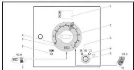
0/0UIPyNI = 0uipyni
(1)
2AkkbipatTkbll
③ BaKbInay wAmBIn anDbIn ana KbI3dbpy (KbI3bIn)
④ Kymbicka daa bHbik 6akblay waMbI (Kb3bn)
(5)KINT KCKBILbI
V2.0 apamuenTepi jko peXmI (HDS 13/20, HDS 17/20 yuih KocbIMua)
7 AnbHfblXanKbHTbH/anaTbIK eWHiPyH 6aBnay WAmbl (Kb3bn)
⑧ CybIKbcTbIK cydblK KymBcpeXMMI (0-100°C)
⑨ Aa3daH KopraydbH JyMbicpeXmI
V3.0 & V5.0 apamuenTepdi xooDBH XyMbIC pexmIM He mece by pexemimH Jxmbic pexmm (HDS 13/20, HDS 17/20 yuH Kocbima)
Tipkey KxkataTapbl
KybpbIbfa apHAnrA hipkey kyaTapbl 3neKTp KaaBbIaTbpbIhN KaPbHaDa caTaIaNbI. Wka TaBmday yuH KybnITnFaH.
KanbintbiXymbicnncnnnei
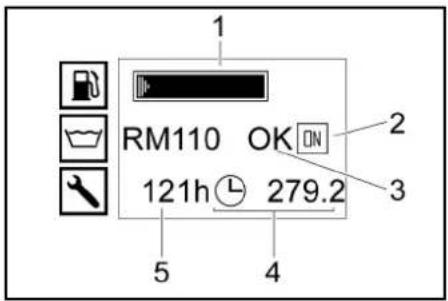
①KaHapMaB 6aBb (KepeTeKiiX konaBb)
2Ko3fantkbil Kocybl (KOCYbl) Hemece Kofantkbilewipnyi(OTUIPYI)
③ RM110 cybikxymcapTkbiu/CHEMxyfblw kypanra aphanra biibci (kapaam/b6oc)
④ Kymblic yaikbltbihl bcenteriui
⑤ Keneci Kbi3MeT KepeCyTeReiH XyMbIc yaKbTiB
Hycay
Kyfbiu kypanfa aphanra biobc Kepcemkiu xyfbiu kypanra aphanra biocbbH anbHda monraH abkmanrah karda dara konxemimiD. Kaibnmb ymbic dbapbcHdackapcy nynmi duonneuihe Keineep keeken H KepceminiO:
KanblmbI XyMbIC
Kb3Mem Kepcemy: mymbHybIbnapra Kb3Mem Kepcemy apkbln miucmi mexHxkanblk Kb3Mem Kepcemy xMybIcmaps (Kymim Xhe mexHxkanblk Kb3Mem Kepcemy) denimin kapaB3). BipHeue mexHxkanblk Kb3Mem Kepcemy KMybIcmaps bKepe 6oIca, onap biPHeH coH biPj Kepcemedi.
Eep mexHuaBik KbAmem KcpCemmyaHdaynapb6bnMa, ducneuKcpCmimUdi
- Akaynbik: akaynbik opbH anobi («Akaynap Kea3Hoei KEMeK» GeilinmH Kapahb3). BipHeue akaybnk bocnca, onap biHcH bpi Kepcemineoi.
Eeep akaynbik bonnaca, 6yn ducnneu kpcemimmeudi.
Aa3daH Kopray KypaBbI Hcnnnei
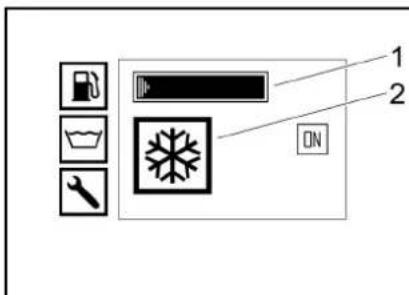
① KaHapMaB6aBb(kepeTkiKxKoNaBb)
Aa3dAn KopraydbH KyMbIc peXIMI
Korapbitereypini nctonet
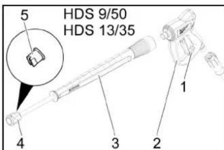
① KofapbblkbicmbdbnntOnetTTiCaKaTahdbipfbblb
② Korapb tereyipin di nuctonet
(3)AfbicTytiri
4)CaJIMaJIbI COMBIH
⑤ KofapbI KbcbIMdbI wTyueP
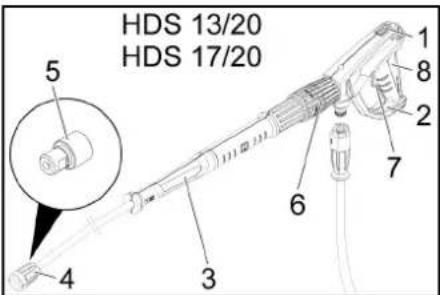
① KofapbblkbcbimdbnCToneTTiCaKaTahDbipFbllb
EASY!ForceXorapbkbicmbnnctoneti
③ EASY!Lock afbHdb Ky6bpbbl
4EASY!Lock canMaNbIcMbHbI
⑤ Kofapbki blicIMdbI WtYuep
6 Korapbl KbcbIMdbnHCTonETter KbcbIM/Menuep peTteriui
(7)CaKaTaHdbIpbfBmHnHTperi
(8) Icke Kocy TyTkacbi
PaiDanaHya 6epy
ECKEPTY
Kapakam any kayni 6ap!
KpybIrfBHyH,Kepek-JapakmApobH,Kyam6epy
XenepinH XeHe KocBnBIMApodBnOypbcXymBIC
icmen myprAhn mekepiH3.
Ocbnap Mynnikc3 mpyde 6oMaHaDa KpybIrfBnH
Koanda6aybl muic.
KypbInrBihbOpHaTy XHe Typanay
HA3AP AYdAPbIHbI
KypbInfbHbHwekmehmbICkb13bin Kemyi
KypbIbIbIHbI WEKMEN bIc KbIbIN kemyiHe KOI SeBMeH3.
Ophamy opHb muicmi mypde xendemineminihe ke3 xemki3iH3.
HA3AP AYdAPbIHbI
KypbInfbHbHaKaynbFbiXaHe 3aKbImdaHy Kayni.
Kymblc KeiHDe KypbInrBk Ondehn Xamybl KepeK.
PnIaIaNbIraHra3Iapra apHaIraH cHbIaIyB JxabIMaTbIHdAopHAtOpHbTahDaH3.
1. Typak texeriiin KynbntaHb3
2. Tipektik dehrelekti can kemerimeh Tycipih3
3.AkipatbtaHbIn Ka6eBJI cypeHTIN KeIKeTeA
4.KenlkiXkapbIKaTaNbIpaTbHxanFarblUbTa bKbIpaTbIn, OHb TaPkbIUtFaBlaa YcTaBbHa KcObH3.
5. KpbIbIbI aHnBbI kneteyI yin I naIaIbn bIbI cIpyra KpaCbI TipeKtePdi EkeITiHa.
6. CypeinTIN KeiikTaXbipaTBHb3.
7. TipeKtik dHreIeK akpblb Kpyblfblb H kondeHeH erin TypanaHb
AnbHbI Xankbltlaay/ka6y
1.AaHbIgXaKbIgKyIbIHcKeKcbHbI. AnbHbIXaKbIg60cKyIbIg aWadI.
2. YcTafbiW INMeKTI TapbIn WbIpy apkBnI aWbHb3. AnbHbF KAnkbbl ATOMaTbTy Tpye KeTePineJI. KaBy KezHHe YcTafbiW INMeKTI opbHbA TyCKeHHe Ke3 XeTki3H3.
Motop
- KozraNTbH MaBihH DeHReHH TeKepin, MaH DeHRei MINMaHIHeh TEmeH TyCe, KpbIITbHbIa NaDanaHaBn3.
- KaXeT 6oNca, MaIdbI ToTbIpbHbI3 (Kytim XaHe TExHnKaIbIK Kbi3Met KepeCy) 6enIMIH KapaHbI3.
ApaJIkKeTeK
- ApaIbIK kTeTeHIN MaIra apAInrHaM dAne HEnHeHdIerMa DeHReIH IN TeKecPeIH3
- KaKET 6ONa, MaHbI ToTINbIbH3N(《KYTmJHeK E'THXKIAbIK KbIbEMet KePcTeY》6ENIIIMHKaPAHb3I).
Xorapbl KbcbIMdbI copfbl
- Man 6aftbHdaftb Hemece Xorapb KbcMbCopfbdaftb MaJ DeHreIH TeKcepH3.
- KaKET BONCA, MaNDb TONTbPbHb3 (Kytim KxHe TexHNKaIbIK Kbi3MET KepcTeY) 6eIMIN HapaHb3).
CaNKBiHDAaTKbIiCynbIKTBk
- K03aTnKbIu CByk Ke3e Ko3aTnKbIuTbHIn CAnkbHaTaKbUc BykTbFbIHbTeHectTipy BldcbHdaFbCAnkbNtAaKbTHbUc BykbTbFbDEHeTReHIn
TekepiH3.CyBbTbIK DeHeTRei MINMEXMAX) apabciHa 60nyIepeK.
- KaKet 60nca, cankBHdAaTbHc cyBtBfHIn KhyhB3 (Kytim XeHe TexHKnabIK kI3mET KepCey)6bninH KapaHb3).
- TeHecTpy bIbIbIcIaIbfI aIaIaIaN KOPAY KOHUEHTPAaIcBbIN TEKCEPIH3.
- KaKet 60nca, a3aDn Kopray KpaanBn KynBnB3 (Kytim XeH TeXnKaBbIK Kb3MeT KepeTy) BenIMIN KapaBbI3).
Aya cy3rici
- Aya cyariciH TeKcepiH3.
- KaKet 60nca, aya cyriciH TaanaaHb3/ aybIcIbpyHbI3 («KyTm XeHE TxHKeAJIbIK KbI3MeT Kepcety" GenIMIH kapaHb3).
CynbIK KymCapTKblWBH KybnHbI3
CynbIK KymCapKbIu KypamBnHa eKtac 6ap aBih Cymen Kymbcic terehe Kblnby typeKtyTinHKnabnneHyH 6ondbpMyuyiH eTe TmId. On KaNTkBaKepaadBepeyxncicHe TaMlbnTaBn Kocblnabl.
Mennepny 3aytta cykepektirIH optraa deHeiree OphatbIrfan.
Hycay
Czykub kymcarmkibumka aphanrah yneinep KOHMeHepKemkiy KeNemile KipeiD
1.CyBikKYMcaptkbIkaAPAanfAraTOnTbipy CbaHbayib aabHb3i.
2.CybnKymCapTkblBihKynBhl3.
3.CybnKykMcapbTkkaApaHnAfraTOnTbpy CbaIbayihXaaBbIa3h.
KaHapMaKyIO
KAYIN
Japamcbi KaHapMaui
KapbInbcKayni
TeK dusbok omblH HEMOC JxHIN Kxblimmy MaBH KuyuHb3. KapaMb3KaHaPmau, Mbicanb: 6eH3UH Kondahyra 6oMaIbO.
Hycay
B5 duouen (EN 14214 - Eyponanbck
cmaDapmka cukec) naDanaahrae ke3de aphaubi
naDanahy, k3Imem xhe mexHuaKbn K3Imem
kepcymw aarpmmabn Cakmay kaxem emc.
Hycay
B6-dan B20-ra deuii6 duoduzenin naudanaehran ke3e (EN 14214-Eyponabik cmaohapmka caueke) dusbenbdko zaranmbuoka e3zepmynp enaizy kaxem. CohBMn Kamaap, apnaib naudanahy, kblmem kanee mexHuaNtBkMm Kepemywapmmbpahckmay kaxem. Ekimemi Yanmar Dunephe xaabapnacbHb3. 1.bldcKaqarfbn aushbI3.
2.Диьдik otbHbJxHaJaMai 6aBbHbI KeTne KybblpApKbHbTOnbTbPbHbI3.
3. bIbIcTbH KaNaRbH Xa6bHbI3.
4. Tereinre Hn3eBbik OTbHbblc cyptiH3.
Ta3anay KypaJIbH KyIO
TekHDS 13/20HDS 17/20
KAYIN
Konaucb13 ma3anay kypandapbl
Kapakam any kayni
TeK KARCHER eHIMeepH KONDAHBHb3. Ekwah epimkiuemepdi (MbCanb:60hun, aemoh, epimkiu) KyuMaHb3.
Keae3 xane mepie muaiyed anyak bonbHb3. Taanay kpanb endiyupicih kayincidik xane na dananahyckaynapbH opbHdaHb3.
Hycay
KarcherkeMaanayKeHcyMIMkacayKypaBnBHyb 6dapmaCabHycbHaCbDcI30h DunepH3 KyaHa KHeC6peDi
- Ta3anay KypalbH Kyio/aybictbpy.
Batape
Hycay
Kpyblrbcepaumbkype mexhukanb kBk3mem Kepcemneumih Gamaparenm Xa6bokmanfah.
BatapennapaabH kayinci3ik HycKaynapbI
Ebatapenebnapdi nainanahana hKeane eckeptynepdi mHJeTti Tpyte opebunhaiz.
Epaaternbl kondaHy HcckaynbfbHdabf Xehe kenke aphanraan naandanaHy HcyckaynbfbH opbHdah31

Ke3di KopFay KypaIbIh KInHj3!
BanapbkbkbnDah XeHe 6ataperrnapd an aynak yctanbl
KapbInbc Kayni!
Ept, yuKbHbIyBfapya, aUbIK uMaFRA kHe TeMeKi weryTe TbIM cAIBHaB!
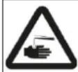
Xmnnnblk kynik kayni!

Anfawkki kEmek!
Eckepty!
Tynnnaay!

BatapeHbKokbcKewirHe TactamaHbI:
△KAYIN
KapbIbc Kayni!
Akkymyamopnpra KypandopbHemece conapra YKcac 3amnapbo KoumahB. Bckka myukmany Me Jxabpyi Kayni.
△ECKEPTY
Ynany kayni 6ap!
Kapa eukauah KopraibHa mui nemneyi Kepek. BamaepaamepnMycb icmen bonraoh coh apkaau H Kofblb3o maanaHb3.
ECKEPTY
Xumunabik kyui kaynil
Akkymyamop KbiukbIbIMeH XyMbIc icmeoHde KbiuKbIra M3iMoi K3iNdiPik, KonFaT XaHe anXkAnKbU KuiHJ.
BatapeHbI 3apraTay
KAYIN
Kapakam any kaynl 6ap!
BamapenmH Kymbc icmeeHc Kayincldik epexenepiXane 3apdmaay kpbInbcsin hOipuyi bepaen naanany HcykaynapbiOpbHaB13. BamapnBe mekcaek 3apdmaay kpbInbcsImeH 3apdmaib3.
- BatapehblbaxbipaTbHb3
2.3apTayKpybIybcIbHbIH OH nonIOciH6aTapeRbHbIH OH nonIOciHE KcObHbIa. - 3aprray KpybInfcBihH Teic noJIOci 6aTapeRbHn Tepic noJIOcH eKcbHb3.
Kyat aasbchn 3apdty KpbIbIbIcbHa cabIbH3
XaHE KocBbH3. - BaTapeHbI eH a3 3apdTay TOrbImeH 3apTaHbI3.
KorapbI KbICbIMdbI NnCTOnetTI, aFBc TYTirIH, canTaMaHbI XaHe XorapbI TereypiHdi KybipuekTe OphTaBbHb3
- Waubipaty K6bipbmeH KOJImeH waubipaty nctoJetIH 6ip6ipimeH KocbiH3.
2.AfBH TYITIHIIb BYpaHdaJIb KcOblIMbI HMbIKan 6ekTJ3. - CanMaJIb ComBIHJaBfI KOrApbl KblcIMbl WtUepePi OPHAbHbI3.
CaMnAbMbOcHbMOHTaXdaHb3KxHEOhB MykTaN6KTHlH3. - Korapb tereypinki Ky6bpwekTI Xorapb Kbcimbl nCTOJETKE KaIraHb3.
HA3AP AYJAPbIHbl 3aKbIMdany kaynil
Korapbmeeyipihki kybipuek kbiscim acmbhd.
Opkauan konrapbmeeyipihki kybipweekmi monbIbmenbocambHb3.
TekHDS 13/20,HDS 17/20
HycKay
EASYLock xyueci kOmohemmepeipdip opuhanbIMMeH xbldam uibapabmibh bypama apkbln jxblndam xheayinclkocabdi
Cydbl Kocy
Kocblm MнДерг� TextHnKaIbI DepeKTePeH KaBHaJIb
- Cywnahricinwnahr opamacbihn 6ocatbn, onbl cy 6epyre kocbhi3 (Mbcanbl, cy wymeri).
Cy 6aBbH Ta3aHaHbI3
- Cy 6arbiHbH Kipic yMeryiHaBHy3.
- Cywnahricinwnahr opamacbHAnbocatbn,Ohcy 6epyreKocbH3(Mbcanbl,cyWymeri).
- Cy kipicih aibHbI3. Cy kaTapbl KaNTkb KaMepa apkblb TOnTbipbnaIbA. Cy kaTapbl tonraH Ke3de KaNTkb KaMepacbHaFb KaNTkbJbI KbNaan Hxa6bIaNbI.
4.Cy6epydiXa6bHbH3
- Cy wnahricih cy bepyeH axkbpTaBhlb3
- Cy wHaHrcIH wHaHr opaMbHa aHaHaIbIpbIbIb3
KoIndaHy
KAYIN
XaHrbiu cyubikmbikmap
KapbInbc Kayni
KaHfbli ciuyibkmbikmapdbi wauNaHb13.
KAYIN
AFLH mymiah1c3 xMybic
Jkapamak any kayni
KypbIITbHbI arBH mymieih ophamnau KondaHaB3.
Op KondaHy anBDhaArBH mymiaIH mbIr3
opanaackAHn mekeepHI. ArBH mymieHH
6paDanaapBn KonMeH mbIr3day Kepek.
KAYIN
Xorapbi KbicmbocI cyarbiHbi
Kapakam any kayni
Icke KocyuuihipeaMeHcakmaDbipBiuuHmipeaH ickeKocbinraKyudeewkaanBekimneH3.
CaKaMaHdbIprbIu uHmpei3aKbIMdaIraH bOnca,
Jorapb KcIcbMbNucmonemmi konDaHbI3.
KypbIrfbaKe3 Keaeh XymbcMbOpbHdAmac bpybH,
Jorapb KcIcbMbNucmonemmei caKaMaHdbIprbIu
memiaH anra kapaU umepHiz.
Korapbi KbiBimobi nuommon nen arbiHkiybpdiE kki Konblb36h YcmaHb3.
HA3AP AYJAPbIHbI
Boc xahanpaB a2bImeH kymblc icmey
KaHaapMauCOPrbcbHbH,0y3bInybl
KpybIyIbIbIy eWkaaH boc XHaapanM daBbEmn IcKe KocNahbI3.
Kofapbkbcbmbbnctoletti awy/k6y
- KofapblkIbIMdbNINTOTETIawlbH3: CaKaTHdbpRbIiNHTiperMeINcKcOyMiHTiperH 6acbIbH3.
- KofapbI KbICbIMdbNINCTOJIeTTI JkAbHbI3: CaTaNDbIPBbIw nIHtiperi MeH icke kocy mIHtiperIH 60caTbHbI3.
CanTamaHbi aybictbipy
KAYIN
Kapakam any kayni 6ap!
Korapbkbcbimbo nucmonem Kbcim acmbHa. Canmamahb aycmbpmac 6yphh, KpbntbHbeewipin, korapbkbcbimbo nucmonemmy KpbntbRkcbmbbwekehe naadanaHBH3.
KybblfBhlbUilpIn,KybblfblKlcblMbI KOBblfHaHlaXOFapblKlcIMblnCTOnetTI naIanahanHbIa.
2. CaKaThaBbIpyBtTeTikEpiN aHa Kapai tHepin, XorbaPb KbcBcMbDpNctonetTi Bekithi3.
3. CanTamaHbI e3reptiHi3
Cy 6epy
Cy 6epy cbtpkbl cy 6epy apkblnbl Hemece iuki cy 6akTapbl (2 x 250 nItp) apkblnbl kAMTamacbi3 etiny MYMKH.
Wap KpaHbIHbIH KaTapy afbHbIHbIH axbipaTkblbI
Koarabic 6aftbItbHa napannenb opHanacy: Xorapbl KblcMbdl copfbldah KeeneIH aHnma cybl KaTtAe3k3y KnaanbHb Adbk 0bnfahanKe3de KaNTkbk KamepaFra Tycedl.
Hyckay
Kon bypikkui nucmonem wap kpaHbHbH ocbl KyuHoe
Xa6bnraH Bonca, Kpbnbl Kbl3bn KernyHe
baunahbcmbi biphewe Muhymmah Keuih ewyi MymkiH
(«Akaaynap KezhiDeoJI KEMeK/KATE 3» Benimin
kappa3).
Ko3raBnBc 6aftbTbHa KeIeHEnOphAnacy:Xorapbl KblcMbbl copfbdaH KeTeIH aHaHIma Cybl KaIta etK13y KlanahbA bAsk60fHaKe3de cy 6KaTbPaHb TaCeDi.
CbiptKbl cy 6epy
- 华KpKaHAnbH Kepi arBn KocBbHbHbBackapy HntIperIH KosraIbc 6aBtIbHa npaIJIeB opHaTbHb3 (20 n).
- Cy 6aBbHbH Kipic WMyerih Ka6bHb3.
Iwki cy 6epy
- 7ap kpaHbHbN KAItapy afbHbHbIN abkpTaKbUbHbH b6ackpy nHITiper Ko3ranBc 6aftbTbKa KeNDeHeH oPhaTbHb3 (500 n).
- Cy 6aBbHbH Kipic WMyerH aWbHb3.
KypbInrfbHbI Kocy
HycKay
KpybIITbIbI mek andbHbI xankbIbI xa6bIK bONrHa d
backaprya bonaDbI. AndbHbI cporbiu KockbuBn
aukaH aKe3e KpybIbI oweidi xhe BaKbIay waMbI
xaHaabI.
Hyckay
XyMbIc KbIbMbHa monblk XemKeHue, K03rAmlKbIu XblndAmBbIbJxidemy npouecie 6aunahicmbI e3eepY MyMkh.
1.KeedenewipriwiTapTyapKbInbKnnbHaaBbH3
2. ApTkbl XankblTb alWBHb3
3. Cy cepydi opHaTy.
4. KINTI KINT KOCKBILBHa cAnbHb3.
5. K03rAnTkbIw cankbH bosraHa rana: K03rAnTkbIwTbI anDbH ana kbIdbpy yuH iKNT KockbIwH con xakKa bypan, anDbH ana kbIdbpy 6aBkayn wamblvctan TpbHbla.
6.KIITTI KockblItbIK I KyHHe BpyaHb3.
KyMbICKa DaBHbIK BakBnay WAMbl KaHaDaBl.
Backpy KepeHi KocblnBn, DcNne N MyMbc KynH Kepcetei.
6QoFanKbIu KcBInFaHua, KiT NCKbIuBH OH XaKaKa 7DvaHbI3.
8. KpbIbIbI KoKbIbIbI cybIbIbCTbIb cypeXIMHe KObIbIbIb
9.CaKaTaNbIpyBtTeTirH apTka Kapa HtePIn, XofApbI KbcMbIDnNTCTOnTeTTIH KyNbHaawbH3.
10. Korapbki KbcibmDbl 6pyikkwiTa aBHB3.
CybIK cyMeH XyMbIC
- KpylbfnbHnKoKbHbHnO/OIbPnyI (JkaHaPbI eUplpyi) KnyHe KoybHb3.
blcTbIK cyMeH Kymbic
KAYIN
blicbk cy
KuimiKayni.
blicmbik cymen XaHacydaH aynaK 0oJIbIbI3.
- Kypblfbl Kockblwbi KaXeTTi XyMbIC
TempepatyacbHa (MaKc. 100^) opHbIb3. KaHApBbIOcbIbIbI.
KbɪnʌdʌbɪkTbɪ bɑckapy
TeK HDS 9/50, HDS 13/35 (HDS 13/20, HDS 17/20 yuHH KocbIMua):
Hyckay
KoIaIbMbHbHbIaDAmbIbIbIbIbApabIaNaca, yMbcI KbcIMbIbaapnaIbMybMaHOmepeHOKyra 60bnAb.
KbIaamdbkTbI apTTbipy:
2. JbIaMdbkTbI backapy TTKacblH XOFapblb6acblH3.
KbIaMbIKbIa3aHTy:
3. JbIaamdbkTbI backapy TytkacbH TeMeH 6baIbHa.
Kmbic Kbcmbi MeH aRbIH XblnDaMdbfBOpHaty
TeK HDS 13/20, HDS 17/20
- KofapbI kbIcbIMbI NICTOETeri kbICbIM/MneJIeep peTteriHJ (+/-) 6ypan JyMbIC kbICbIMMeHKeTki3y kbIbIaMbIFbH peTHe3I.
KAYIN
Xapakam any kayni 6ap!
KbIcIM/Kenem pemmeziuih ophamy Ke3Hoe aeBHy mymiaHdea bypaanbKnocblnbMcBn Bocan KaMAYbH (KaDaRaNaHb3.
Ta3aay KypaIapbIMeH naIanaHy
TekHDS 13/20HDS 17/20
HA3AP AYdAPbIHbl
JXamcbt3yjBtli Kypandap candapbHAn 3aikbmdany kayni
XApamcb3J KpybIu KypanbIb KondaHy apkbln I KpyblnIe JKeA mazanaHambIaMbH 3aMlbH 3AkblMoHdyI MyMKH.
Tek hicahra aphanran kyybiu kypanbni naaanaabHib3.
Kopuaafan Optahny Kopray yuih Taanayah KypanaDyHMyHmJnaiNaidaanBHyb3.
Kyblu KpapanapsMeH6pre 6epinre MeIeepney 6oBnHa ycbHCTap Me HcaynapdbOpbHdaH3.
KpybIfblbEhDipyuCiMaKyUdaFahJyFbIu KypanapabHHraNaaJaHaHyra6oJaBu.
Karcher KommaHnBcIbH Kyfbl KpaIaapBn KondaHaBbIb3O da KypalnbKepepric3 Kymbic tceyiHe KeninOme6epinei. CIe Kehec 6epyre pykcat eIH3 HeMece b3dH katanoTb HMece Ta3aIbAa 3aTTap TypaIbIaknapaTbIK npapaKTbIM3db cyPah3b.
1. KyfbI W KypanDbH copy wnaHrcic H KyfbI W KypanDbH epirtnici6ap bIbIcKa canbHb3.
2. Tanaay KypanbH Mmeppey KnaanbH KaKeTTI KOHTpaun DaHReHHe KObHb3.
Hycay
Kyfbu Kypammen Jxmbic icmeeHoe khe kon 6bpikiu nuonemmi xabnrah ke3e cyfbiu Kypandbi KaimkbkamaepacbHa Hemece cy baabe Kauma arbn kemyihi kon bepmuyuihmazanay Kypanbu Menwepey NkanaHbXabkbo nybkep.
ApamwentepjXoIO
Apamwentepdi koo V2.0
- KpybIITbKocBbUbH «ApamwENTepdi KIOU V2.0» Kymbic pekIMHe KOJIbHb3.
- KozfarTbblKocBtflraHua, KiTT KocBtblH OH KaKaJa 6pyaHb3.
- CaKaTaHbIbIbIbIeTetirH apTka Kapa Hrepin, XofapbIkbicMbIDnCTOnETIH KynbH awbHb3.
- KorapbkiKbcimDb6ypikkwiTaawbHb3.
Dmcnnnei TEMPLOWXyuein KepeetediKyMbIc TempepaTpaBHa XeTeY yuHJ WAmameh2-4 MNHT KaKET.
-Диспгел«TEMP OKAY»Жуиесин КерсетeД:
5.Apamwentepdi xohodobpbiHdaHb3.
Apamwentepdi koiO V3.0 & V5.0
- KpybIfbKocBbUbH ApaMHeTepJi KOH V3.0 &V5.0» XMybIC peXmIhe KoYbHb3.
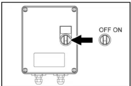
2.WK KopaniwacbHbH Kocbin, KockblTb «KOCyIbI» KyiHe KoiBhl3.
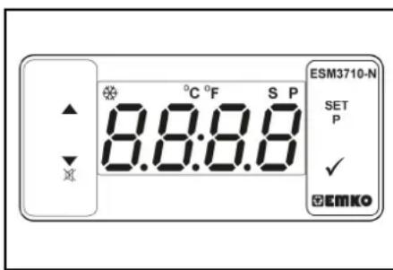
- «SET» 穴亥(A»Y)TynmepinnaaanabnI TEmnpatypaHbOpahbHb3 穴亥(V)apkblnbI paactaHb3(Duaanaoh aykbMbI 85-105°C).
- Koarantkbilu KocblinFaHwa, KiTT KockblbH OH, KaKKa 6ypaHb3.
5.CaKaTHbIbPbIITeTirIH apTKa KapaH nTePin, KOFApblKbcBIMdbNCTOENTTIKyINbH aUbHbI3. - KorapbkiKbcimDbI bypikkwiTaawbHb3.
HycKay
XMybMc memnpamypacbHa xemy yuH wamAmeh 2-4 Muym kaxem.
- Apamwentepdi kooDbI opbHdaHb3.
By pexmi (6yMeH Ta3aJay XaHe de3nHΦeKuJnay)
TeK HDS 13/20, HDS 17/20 (KocBm)
Hycay
By pexumih naaanahy yuih xibindaombikmbi
bacapamib6ekimjxuhafl (kocbImua, 6ypbHfbl
3aybm:2.013-086.7,kauma xa6bokmay xuhaflb:
2.013-014.0) eme kaxem!
△KAYIN
Kyul kany kayni.
XJorpaBj xMybMc meNemepamypacbHa baaunahbmcbl XJyMbIcKbCbMnHbIHxORpaBnPaBy.
105^ KorapbJyMBCm MemnepamypacBHa JyMbIC Kbcmb3,2Mpa(326ap)acnaumbiHbHaKe3 Kemki3i3.
Hycay
Bmyen mazanay Ke3iHoe 2 afbihbkybipMeH xymbc icmey MymkH emc.
- Bymeh Taanay: ceKec 6yUmyerIH aBic TytTirHe OphaTbHb3 (6enwek Hemipi《TexnkaIbIK depeKTep>6enMIImHeKapab3).
2.Дeзинфкунay:WR10,20,50Hemece100 Kopa6bI arbcTyrHirOp 0p7aBtBu3xHe CoJIkec6 By UymeriCanbHb3 (6enlEeK HEMIPIN《TexnKanbIK DepeKTeP》benimieHkapaHb3). - Kypblfblckbiwblh «BypeKIMHe» opHaTbHb3.
- WK KopranauacbHbHKcObIn, KocbHbTb «KOCyIb» KVIHHe KOBbHb3.
- SET> XaHe TYMmepin naIanaHbIn TemnepaTpyaHbOpHaBb3XeHe 工 apkblpaTaahb3 (ycbHbInaTHdnana3OH aykbMb1 120- 155^)
- Ko3raNTKbIuKocblIraHua, KJIT KockblIbH OHKaKa Ka 6ypaHbI3.
- KozraTbIi KanotbH aiBbH3 xHe MAHOmeTpdi 306apra deHH pettey yuH KaHTa eTKi3y kanaHaHdaFbTyKaHb carat TiHe Kapcb 6ypaHb3.
8.CaTaNbIpyBtTeTirH apTKa KapaN tepin, KOfapbKbcMbDnNTCTOJeTTH KynNbH aBbH3. - Kofapbkbcbmbdb6ypikkwiTaawbHb3.
Hycay
Kymbc memnepamypacbHa kemy yuiH waMaMeH 2-4 MuHm KaXem.
10.БуMuH Ta3aNaay Hemece De3nHΦeKuRnaaybI opbIHdHaB3.
KayIncl3dkyHKnnaIapbl
1 WR KopanwacbHbB 6akbnay 7ambl Kbl3bl TycTe KaHabI: JyHe KbcIMbl TblM Kofapbl, XaHapFbl eWefi, aynap Ke3ihderi KeMeK> 6enIM H kapaHb3.
2 Bacapy naheinneri dinnepeKATE5naia60nabl:kyne kibcimbl TbIM ToMeH,KaHaprKocblma,bkAaynapKe3iHderi KemeKATE5 6enimHkapaH3.
Xmbictb TokTaTy
- KofapblkbicbIMdbnCTOnetTIkaabHb3.
- KaTahnDbipBtTetiriH anfra Kapar iTeprin, XoRapab KbcBbMdbIh nctonoteti Bekitih
Hycay
Eeep Korapblkbicmbu nucmonem kablnca,
Ko3ranmkbbloc xypic kbindamboihda yMbcih
kAnracmbpaBb. BycDhBkanmkbKaMepa Meh
Korapblkbicmbb copBb apacmbda auHnybHa Xhe
kIbyha ekenei Pycam eminzen en Korapbl
memnepamypara (55^) xemce, Ko3ranmkbu cy
kipiciidei memnpamya damueia apkblb uipinei 50^ mEmeh cankbdaarHHan keih KpybInbHbApb
kapau naDanahyra bona.
Kyrbliu KypaJImeH KyraHHaN KeiH
TekHDS 13/20, HDS 17/20:
- Tasaay kypanbHmEnwepney knanaHbH 《0》 KyHHe KOHyB3.
- KpybIbIbIbI bKofapblkbIcMbIbNtOJIeTIaBbIK Kynde KEMdereHde 1 MNHT WAbHb3.
KypbfnfbHbEwipy
KAYIT
blcmy kayni.
bcltbik cybbl naaandaHann KeiH KpbIbnHbI cankbhdamy yuH nucmonem aubk kyuDE keM deeHbe 2 Muhym cbik cymen KymbcIc Icmy kepeK.
HA3AP AYdAPbIHbI
3aKbIMdaHy Kayni!
3akbimdahy Kayni
Kon bypikkiu nucmonemih auibk kyde, monbIK yKmeme Ke3iHoe Ko3rannkblumbI eukawah mokmamnabH3.
- KypbIbHbH KocBbUbH 0/EWIPYJI (KaHaPfbl eWipyni) KyiHe KOybHbIa.
- Kon6pyikkiu nncToTeH kaybin Koibh3. Ko3rantKbiw 6oc kypicTH aiHany caHBn peTteNdi.
3.KJNTI KOKBILITbIOO KyiHHe 6pyaHbI3.
KMybICa daBnHbIK 6akblay 7aMbI ceHdi.
Backapy KepeHy eWu JIe Hne DcNne CeHdi. - CbipTKbI cy 6epy yuH: cy 6epydi xa6bIbI3.
- KpybIfIbI KblcMbIy KOblfAHaHaXoRaIpbI KbICbIMDbI bNCTOnETI NaJdaNaHbHbI3.
- Keaedecok aabIbnin kainmac yuih xorapbl KbIcMbI nctOnetTI caKaTHdbIprbl TetirimeH 6eKITn3.
7.CbtpKbI cy 6ebyui: cy uanharicH cy 6epeydn abkpblb, OHJI snaHr opabMbia anHaandlbpHbIb3. - KorapbI tereypinii Ky6bipwekeTI opaTbIH 6apa6aHaFa opaHb3.
Aa3daH Kopray
Aa3dbi3akBmDahyBihAnKopray yuiH KpybIbnHbI a3aJadKopray KpyaBImEHxyKepek.
Hycay
CmaHdarmmbI camIambIaemOMoBunbdep yuHIp aHpAnrA nIOKoN bHeAl3Hoe uBirapbIurn Aa3aHOn KOpFy KypanbH KONOahbIb3.
HycKay
AraKaPcbI Kpyan EHDipywiicin naDanahy HcykaynapbH opbHaB3.
On coHdai-ak Koppo3nuaan Kopraydbin 6enrini 6ip DeHReiH KAMTaMaCb3 eTeDi.
Ko3fantkbIHTbI a3dah Kopray
- K03faTbIbIbIbIcAnkbHdAaKbIbI cybIbITbIbI aHaJIbMbHJa XeTKiNkTI a3JdAn KOpfayDbH 6apKoFBIH TeKcepi, KaTeT BoCa, a3JdAn KOpFay KpaIbH ToNTbIbHbI3.
2.(CaNbHaTbIiCyBtBtBtTeKcepyXaHeToTbIpy)XeHDeYKMbCTapbHKaPahB3.
BaTapeHbI a3dAn KOpFay
- KaTbI aR3a KpyBnFb 6bpHeue anTa bOybl naHdaNaHbIMaca,6atapereHb 7bIrapbIn, OHbCaNkBIn EmeC xepDe cakTahB3.
CaKbIHdAaTbH cybIKbIaHaNtbyHda aar3aH Kopray KypaBihxy (XoFapbl KbcIMDb copfbl)
1.CbtpKcI cy 6epy ywiH:cy wlaHriciH cy 6epyden axbpatbHb3.
2. KpybIbHbH KCKbIbH «O/ΘUIPyI» (XaHaPbEwipyn) KiyHe KoBbHb3.
3. KypbnrBihBnKbcBIMbH KOBIHbI3.
4. KpybIbI bKocBbIbN Aa3aHn Kopray' pekimHe KObIbIb.
5. Tek HDS 13/20, HDS 17/20: Taanay KpanbH Menwepepye KnanabHm MakcmyM KyiHne KoBnBbI3. Kyblu KpandbH copy luahrCicH xyblu Kpan KaHTeHepHeu bIrapin, obl boc copa anatbHd anetKobHbI3.
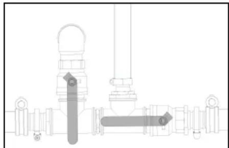
6. KypbHbHbTOnBbImeH 6ocaty yuiH cy 6aBbHbH, Kipic wMyerih XHe tery wMyerih aWbHb3.
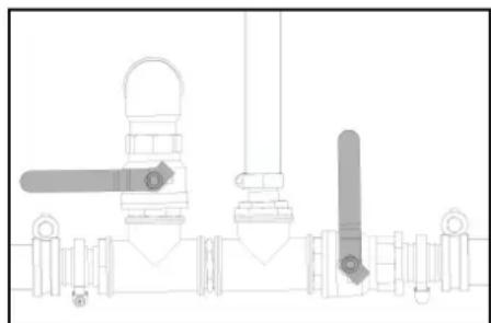
CybarhBnTOnbpyJeHreITobnbImeH TEmehDei.
7. Cy 6aBbHbH Kipic wMyerI MeH Tery wMyerIH Ka6bHb3.
- KofapbI KbICbIMDbI NCTOnETTI XOFapbITereypinDi Ky6bpweKeTHe AxKbPaTbHb3.
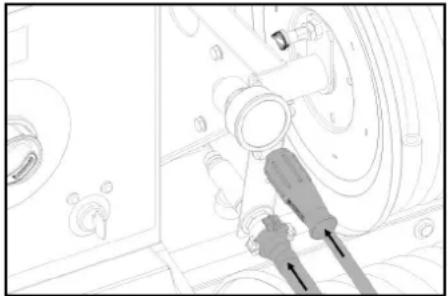
9. Kogarbyi tereypiindi kybipyekti ayaan kopray Kpicike Kocbih3.
- Cy wnaHricih a3dAn Kopray KipiciHe KocbIb3.
11.AaJahKopray cybIKtbIbIbH a3aJah Koprayra apHaTaN bIbIcblHa KcOsbH3c. Cy/a3aJah Koprayab apAnactbpyKaTbIbAcblH a3aJah KopraybIb eHdpuyHyckaynpblHa c8KeC TaHdaH3.
12.AaJahAn Kopray KOHcHTpaIINCBn CaTbIbIMdAfb
a3aJahKopray cbHaBbApkblb TeKcepin,KaKeT
60Ja cpeTeHJI.
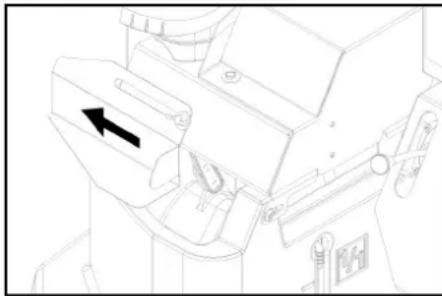
- KaNTbI KAMepacbHbIN TONTbpy CaHbNaybIH aWbHbI.MyHbI cTey WHyK NauTaBbpaHaDaBH 6ocatBnYcTHiKAKNaTbCntra CbPbTbHbI3.
- KaNTbI KaMepacbHa 20 JInTp aar3aH KopFay KypaNbIH KyBbIN, TOnTbIP CaHbNaybIH Ka6bI
- Aa3dAn Kopray Wap KpaHbHbHb6ackapy nHTiperH TIK KyIre OPhaTbHbI3.
- 华KpKaHbHKeiArH KcKbUbHbB 6aKapy nHTiperH Ko3raIbc 6aBtBuHa npaJIeB opHaTbHb3 (20 n).
- KofanKbIw cankbH 6onfHa nfa hana KofantKbIwTbI andbH ana Kb3dbpy yuH KINT KockbmbH conxkKa 6ypan, andbH ana Kb3dbpy 6bkayla Wamblyctan Tybpln.
18.KITTI KCKBILTBI《》KYHIE 6bpaHb3.
KyMbICKa DAHBINBIAK BcBAJlay WAmblKaHaNbI.
Backapy KePHeyi KcBbInB, DinPnneDe Aa3daH
Korpay JxMBC Kyni KepeCtinE. - KofaNTkBIIKocBIIFaHua, KiT KockblbIH OH XkaKa 6paHaIb3. Aadan Kopfay cyBikTbIfb KypblfApKbIbI aHnAbIMda aaidanaDbI.
- Kanfah cunbu aanahan kopraya aphanfah bldbcka anaan kopray unanharicipakbltei
21.Aa3dAn Kopray WnAhnHrciHeH Aa3dAn Kopray KypanbI bKkAa 60Ja, a3dAn Kopray Wap KpaBnB 6ackpy nHtiperH KeJeH eH opHaJacTbPbIn, 5 ckyH KyTIH3. - Ko3fantkbwTbI eWipiH3
- KpybIbHbHIOKcHbUbHIOoJIbPYII (JxahapbE eIpyi) KyIe HObIyIbI.
Korapb KbcimDbj KyneHn A3dbkopray KypanbH TApTbIn WbIfapy
Hycay
Kymbicka Kipicnec 6bytbH, KOFapb KblcBIMbJxueDeai anaera Kapcb cyuibkmk Kaumadaan an3dah Koprayra aphanrta BhoBcBHa Koeepinyi Kepe.
- Aa3dAn Kp4yraJAPKpaHbHbN 6ackapy mHTiperH TIK KYIe OPhaTbH3.
- Korapbi TerepyiHdi Ky6bIpweKTI a3aH Kopray Kipicihe KocBHB3.
- Cy uHaHrciHa3DaH Kopray KipiciHe KocbHb3.
- KaNTbI kAMEpaBbHIN TONTbpy CaHbNaybIH aMbHb3. MyHb ictey wiyu HnKaNb b6paHaDaHb6OcBaTbn, yCTHI KAKNaTb CONa CbPfBbTbHb3.
- KaTbKa KamepacbHa 20 nItp TyuBi cy KyuBn, TOnTbpy caHbIaybH xa6bHb3.
- KypbIbI KoCKbIbH AnAaHaN Kopray' peKmIHe KoiJIbI3.
-
KozfaranKbIw cankbH 60rHaRa rha: KocfantKbIwTbI andbH ana Kb3dbpy yuH KINT Kockbblsh conXakKa 6ypan, andbH ana Kb3dbpy 6bkayna Wamblvctan TybHbIa.
-
KIITTI KOKBHTBI «I» KIyHHe 6ypaHb3. KymblcKaDaJIbIK B6kInay MaMbI JxHaNbI. BaKApY KePHEY I KcBbIN, DnCnpeIe «Aa3dAn Kopray! Kymblc KyI KepcTeJIedJI.
9.603raNTKbIbKoCblfHaHwa, KiTT KcokblshOH XaKaKa 6ybaHb.
Aajdah Kopray Kypaib cybblkTbbl KaTbI kamepaadan TuCybni naDahnBnAa3dAn Koprayfa ahpansan bblcbHsX6fepeinedi.
10.AaJdAn KoprayFa apHnFAh BaIbC TOnFAHua 1uMaAMe2 M HUYT UaJIbH3.
- Ko3rantKbIwTbI eWipiH3.
- KpybIbIbHbIKCKbIbHbI 四 / 0 ΘIPyI 日 (kaHapfbI eipyI)kyiHeKobIHbI3.
TacbImaJday
△AEBAHbI3
Xapakam any mehe 3aikmdoany kayni 6ap! DpybIec macebImoay
Tacbmanday Ke3iHeKpybInffBbHcannMarfbHaHa3ap ayapbHbI3.
HA3AP AYdAPbIHbI
3aKbIMdaHy Kaynl!
Dypbic emec macbimanday
TacmbmdayKeihoeickeKocymkacbH3akbimdanyanckmacbHa
TipkeMe xmbcbi
Hyckay: Kofamdkk Konnapda tipkecmi 6ap cypeiTH Keiikti BaekapatbH xpr3ywi KaKeTIyxpr3ywi KyonirIH (Kypr3ywi KyaniriHnKnaCbi) 6ap eKHe Hee KTekiyi kepek.
KAYIN
Bongxian BonmaumbH Keik kypa3y mepmi6i
CybaBjKapmbaun monraH 60nca,6ackpy KcraIbIcmapbI kammblXacay HEmece mkey XaraIaIbpl Ke3Hde KpybIbI waAkybI HEmece ayadpaNby MyMmIK.
Kekik yjpat3y anbHb3a cy b6aBn monbIbImEH 6ocambbHb3 Hemece monmbIpbHb3.
- PyKcat etinreH xannbI canMaK 1600 Kr 6oNca, cy 6aBHb6OcaTbHb3. PyKcat etinreH xannbI canMaK 1100 Kr 6oNca, cy 6aBHbTOBbIFBMEN TOITbIPbHb3 Hemece 6OcaTbHb3.
- ⅡHrOpAm6oNMAIbTH KpyIbIbIbIbIyIiH XorapBtereepHiDkybIpweKTeXorapBkbIcIM po3eTKacBaIHbYbpan, OHkybPbIbJa caKaTbHaJ.
- Andbblb konaKbI (kocMbua) anfa kapan 6ypan, 6ekitj3.
- ApTkbl KaKaNaKtbl (Onu) TeMeH TapTbIn, 6eKiTiH3.
- TipeKTik DeHreIerImeH TapTKblTbH BIKTIirH cypeTIN KENIKTIH tipKEMe MyfTacbHbN 6IKTIIRHe peTHe3.
- Aakpatalnabtn Kabebn cypein Hekinke Xanrna3.
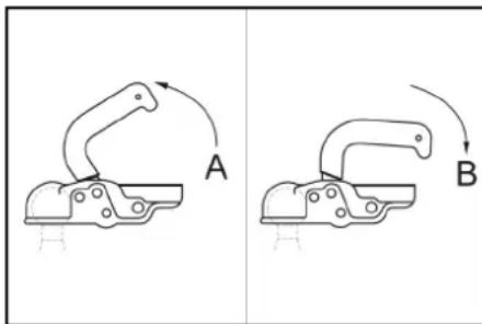
TipkeMe MyfTaCbI aWbIbIbI
(2) Tipkeme myfctabx kabibnbl
- MyΦTa TyTKacBih XOFapbI TapTbHb3 (aWbHb3).
- TAPKbiBti TipKeMe MyfTacbIHbIh IapbHa
- MyfTa TYTkCsBtH TaptKbIka napanJIbe 60bnHaTa TEmeH (XaBbH3) GabCIn ObPbHbI3.
- Kekikti kapbikraHbipatbIH XanrafbIbIeHri3iH3.
- TipeKTik DeHreIerIH can apKbIbI Kofapbl Kapai 74paMbIh.
- TipeKtik deHreIeri tapItraHKe3e TipKemere 6aBttTaNrAHaHbHa Ke3 xetK3H3H.
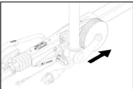
- DeHreKeTepEn Cbipyra Kapcbi TipeKepdi anbln, onapdby yctaftupfca nblb3.
- Typak texeriuih 6ocatbHb3.
- Tipkeme Xapbhtanbpybiv (TekeiHwamdapbl, 6aBapKepcTeKiUteP, Ekpbl WAmdpap, Hemip wamdapbl) Kymbc icten TyprAhv TKepeiH.
-
- Hua npoTeKTopBuHa TaTbpIaH 3aTApDbH 6apXoBbH TeKecepH3.
- WnHaIapDbH Kyin TeKcepii3.
- ⅢIHaBbH KblcIMbIbT KeTcePi3, «Kb3MeT KepcTeY» BenImH KaPbA3b.
Hcyay: tipkemeepi6ap keniiktp yuih xeprinikti XbIaMdbIK WeKeTeyneipin CaKaTbI3 XeHe YcTaHbIbI3.
KpaHMeH TaCbIMaJdA
KAYIN
KpaHdbI dypbic emec macbImanday
KpybIbrHbI Hemece 3ammapobH kynayblcandapabHah kapakam any kanyi
Kepeinikmi kazamaBIM okuranaPbH andbH any epexenepiH KHe kayinciDik HcKayapbH opbHdHa.
KypbIITbHbI KpaHMeB 6ip2e mek KpaHMe Hxymic icmeydi yuphehen adamap mcbimanda anadbl. 2p6ip kpaHMeMbimandaandabHda kemepeiunH3aKbIMdAmHaFaHbH meKcepHJ3.
Op6ip KpaHMeH macbImandoay anbHda mymKaHbH 3aKbIMdAmaraHbH meKcepiH3.
Kybpbltbihmymkaehsana hae mepeh3. Tipeiyu uwhkbpnpabd naudanha6hns
Kemepy KypanbIH yKmH 6aikaycbla3a afBimbyhAH Kopran 6ekimih.
KpaHMeH macbImaIay anbIHda Xorapbl KbICMbdi nucmonemi, canmamanapbl. yken Bemmepei KByfbluBjXehe BaKa 6oc 3ammapbl bp aRbc KvBbBn anbl macMaHb3.
Kemepy Ke3iHde KypbIINbIHbIH ycmHde euw6ip 3ammbi macbIMaJdaMaHbI3.
Kykmih acmbHda mypMaHb3.
KpahnBkyinmi aumafbuHa 60lya eukimae pykcam eminmeunihin echephiia.
KpybIyfnIhI KpaHda iyni Kyude Kapaycb3 KaIbIPMaHb13.
CaKTay
△A6AHJAHbI3
Camaikacmajimaca, xkapamanyko3aikbImdahnykaynl6ap!
KypblfblbMb macbImaoy Jxhe caMay Ke3Hde OhBn canMaBHa baunBaCmbj Kapakam any Jxhe 3aBbMoDy Kanyi Bap.
TacbImanday kane cakmay ke3HDe KypBInrBbHIn canMaBfH eckepiH3, TexHkaTbK MaNymammap mapaybH KapaHb3.
HA3AP AYdAPbIHbl
Ara3daH 3aKbIMdaHy kayni 6ap!
TOnBik meImeHcy KamyltnKan,On KpbIbnMeH KEpek-JkapmApob3aKbMdaByy MyMKH.
KyIbIyIbIaHae KHepeK-kaepaMapaH cybIb MoIbIbMeH arBIsbIh3.
KypbIITbHbI KeHe Kepek-XapakmapobI aar3aH KOPFAhI3.
Kytim XeHe TexHnKaIbIK Kbl3MeT KepCety
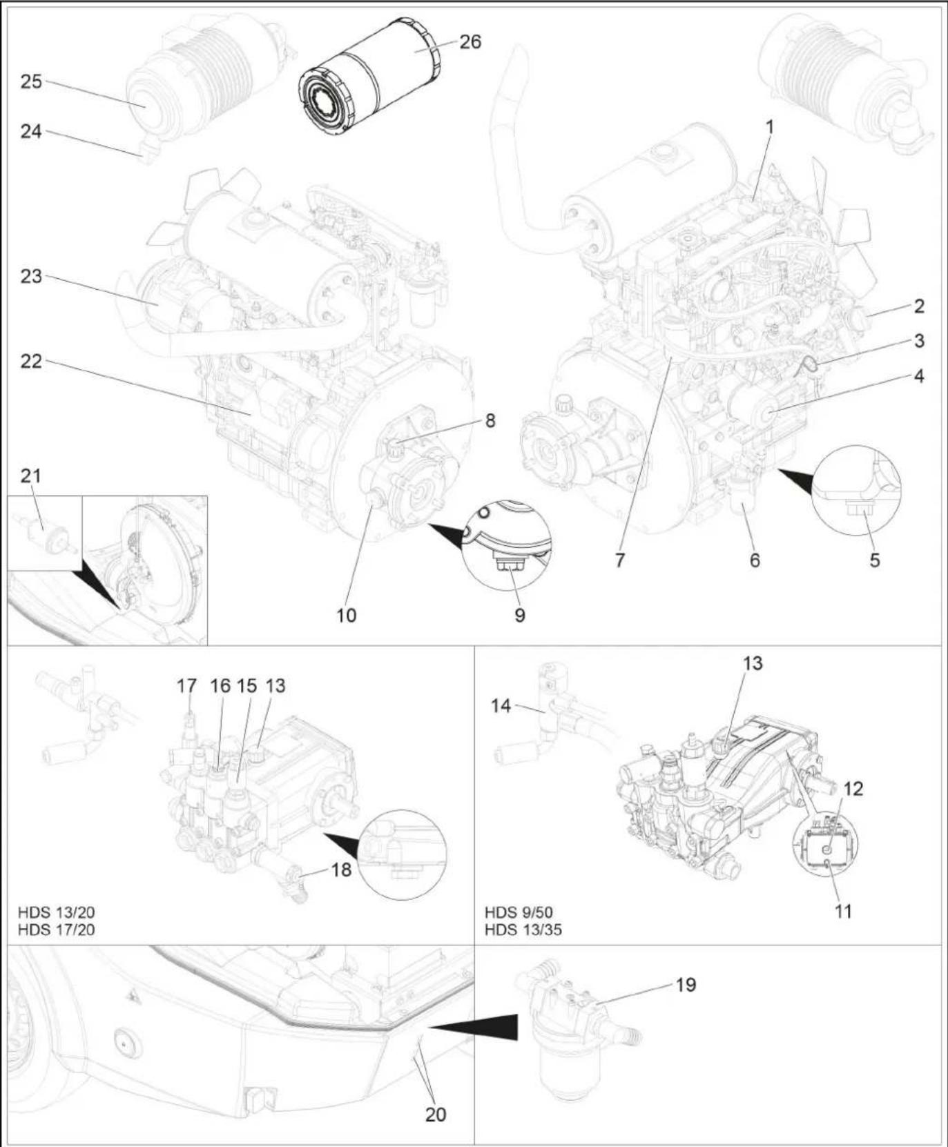
① Ko3raTbIbIMaHbIHToNTbIpyCaHbIaay(koRaPbI)
(2)Ko3faTbIiMaBbIHToTbIpyCaHbIaay(6yHpNik)
(3) DeHre enweriW (ko3rantKbWi)
(4) Mai cyarici (ko3fantKbui)
⑤ Ko3rTbIiMaBnH Teretih Cypama
6Cy Benriu
⑦Kanapmai cyarici
TpaHCMNCCNBAIK MaIbIH TOnTbIPy CaHbINaybi OHbIH iUHHe yPney
9 Apanbik kTeeriHin MaT Teretin 6ypamacbi
10 ApaBik XeTeRIH MaRHa apHaIraH MaHdaen Heri
(1) Man Teretin 6ypama copbcbi
12MaHa apHaHaH MaHaI aHaHE cOpfbcI
13 DeHre enWeeri (copb)
14)KaHaHapfbHbHcKaTaHdbIbPbIi6norbi
15 Aa3dAn Kopray KypaIbI KnanaHbI
16KbcBIMOCKBllbl
17 Kaeta kniy knanabhi
18 KybIw KypanDbH kipici
19 Copfbih andbih ana Ta3anay cy3rici
(20)Backapybactneri
(2)Kahapmai cyarici
(2)Ctrep
23 KapbIKAthIbIpyFa apHaHFaH reHePATop
(24) Aya cyriciHeri KOKbc YbIaTbH KeP
(25)Aya cyarici
Kipicaya cyarici
ArbiH dNarpaMmacBi
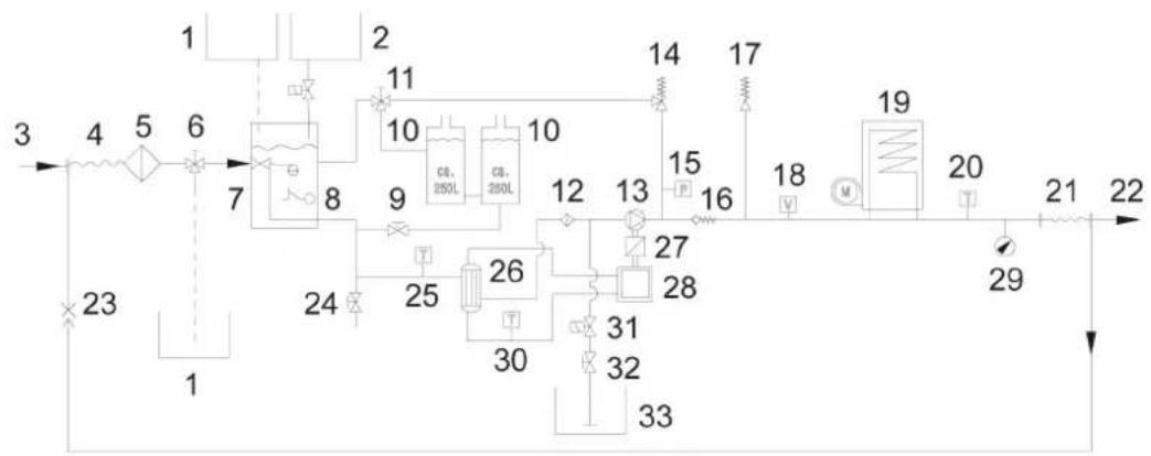
① Aa3dAn Koprayra apHanrA hDblc
② C#yibk XyMCapTkblll bIbIC
③Cy 6epy
TEmeH KbcbIMdbI WnHaR opaMbI
(5) Cy kipic cyarici
⑥ ⑦ KapaHbIbH a3dAn Kopfay kyyneci
7KaTbKaMeepa
(8) Cy tanuibinbihaih Kopray
⑨ Cy barbiHBiKipic Wymeri
(10)Cy 6a#b
11)MapKpaHbHbH KaTapyaftbHbHbH axkbpaTkblb
12 Copbbln andbn ana ta3anay cy3rici
3KofapbkbcbmBb copfbl
14 KaetaeK3yKnanaHbI
(5)KbcbIM Kockbluib
16 Kepi cokkbl knilanbbl
(7)Kayinci3dk KnanaHb
18)AFbIH KOCKblIbI
(19)AfblHbIcYkbblTbll
20)KaHapfbHbH TemnepaTpa daWiri
21 KorapbI KbIcbIMdbI wJHr KATyWkAcBcI
2) KOrapbI KbIcBIMDbI bIbIFc
23AaJaanKopFay KjYncin KaTapy
(24)Tery wymeri
25 Cy kipicinH TeMnepaTpya daTuHi
26)Kbiny anmaTbipfbi
7)ApaJIbIK XeTeK
28Ди3eIb MOToPbI
29MaHOMeTp
30 CankBnDaTy cybHbT empepatya daTuNi
31 KybfH KypaDbH 3neKtPmHarHnTTIK KnaHaHb
32 Taanay KpanbH Menwepey KnanaHb
33 Kyyblk Kypandbk HOKTeHepi
TytbinybinaPafKaB3MeT Kepcety
opTaIbIFI DnCnnnei
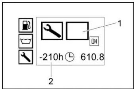
| TaN6a | Тутбуларра КьзмET керсету Турì |
| Жанарыfa КьзмET керсету | |
| КозfantКьшka КьзмET керсету | |
| Сорыfa КьзмET керсету | |
| Жогары Кьсимды пICTOTеТКьзмET Керсету |
TexHKnabik KbI3MeT KOpCeTy Mep3Iminiri
| Укыт hyктeci | Кызmet | Арksыт |
| эрбip canap andbyнda | ЖарытандурдуTekсерінiz. | Опетаport |
| Шинаньи Кысымьи Хаhe Күйн Tekсерінiz. | Опетаport | |
| Кунdenikti | Жогары Кысыддд copынын мандд ошегіндгі майынTekсерінiz.Суті май бүлса, күрьнfyны naйданhanbys.Тусыншларра Кызмет Керсety opталыгим Байданысынiz. | Опетаport |
| HA3AP AYДAPBHyIbI 3akbIMdany kaynil Eeep cymi maß bonca, DEpey Kächer mumbinhyshnapra KbyImem Kepcemy opmanlyfa xabapnaibHiz. | ||
| Кчрыны жалы Күйн Tekсеру. | Опетаport | |
| Жогары Тereypiridny K6bipsek зakimdalmaraнн Tekсерінiz.Зakimdalmfahнжогары Кысыдд suлангтэрпд naйданhanbys. | Опетаport | |
| Су кирсдerri cy3riHiTekcepin, кожet bonca taananaHiz. | Опетаport | |
| Сорыны andby ana Tazanay cy3ricin Tekcepin, кожet bonca taananaHiz. | Опетаport | |
| Козгалы Кыштafы май Deнгийн Tekcepin, кожet bonca, майы ТOTырьнiz. | Опетаport | |
| Аралы кжTeKteri май Deнгийн Tekcepin, кожet bonca, майы ТOTырьнiz. | Опетаport | |
| Козгалы Кыштafы жанapmaу суагсin Tekcepin, кожet bonca Тусыншларра Кызмет Керсety optanыflha xabapnacbIbI. | Опетаport | |
| Козгалы Кыштafы жанapmaу сублiriшin Tekcepin, кожet bonca Тусыншларра Кызмет Керсety optanыflha xabapnacbIbI. | Опетаport | |
| Төнөсөдүхддгы салындахысүыкынDEнгийн Tekcepin, кожet bonca, салындахысүыкынТOTырьнiz. | Опетаport | |
| Козгалы Кыштafы OTbHIn cya3ricin Tekcepin, кожet bonca Тусыншларра Кызмет Керсety optanыflha xabapnacbIbI. | Опетаport | |
| Жугын куралын copy shanrincideri cy3riHi Tekcepin, кожet bonca taananaHiz. | Опетаport | |
| Кчьыр чу�ecinde Тыfызддын Tekceperiiz. | Опетаport | |
| Yakultnyhukteci | Kb3met | Apkullb |
| ЖуMbICTb anrauksb 50 caratbHAN keiHbip pet | ЖeIeTeKlUteri sbHaHbIb 6eIaIck KepeHyIN TeKcepin, KaJcET bOnca KaIbTa TapTbHbI3. | Оператор |
| Кo3aIaTbIbTaBbI MauDbI aybIcTbIbHbI3. | ТуltиMuIbnapra Kbl3MET KepCetety | |
| ЖorapbI kIbIIMdbI copbIdaRaMaiDbI aybIcTbIpbHbI3. | ТуltиMuIbnapra Kbl3MET KepCetety | |
| Барлб 50 Jxymbc caratb Hemece 3 ai | БатAPEлардIb TeKcepinI3. | ТуltиMuIbnapra Kbl3MET KepCetety |
| Барлб 200 Jxymbc caratb | Aya cyaricin Hemece kicpI aya cyaricin TeKcepin, KaJcET bOnca TazalaHbI3. | Оператор |
| ЖeIeTeKlUteri sbHaHbIb 6eIaIck KepeHyIN TeKcepin, KaJcET bOnca KaIbTa TapTbHbI3. OpePatoP | ||
| Аралыж eTeKtIb TbIbIbIbHbIN TeKcepinI3. | ТуltиMuIbnapra Kbl3MET KepCetety | |
| ЖaHapmaI bArbIHbN TOntbIpy KeIte KIbIbIbHdABy IeKtI TazalaHbI3. | ТуltиMuIbnapra Kbl3MET KepCetety | |
| Кo3aIaTbIbTaBbI MauDbI aybIcTbIpbHbI3. | ТуltиMuIbnapra Kbl3MET KepCetety | |
| Кo3aIaTbIbTaBbI Mau cyarI 3eIeMeHTIn aybIcTbIpbHbI3. | ТуltиMuIbnapra Kbl3MET KepCetety | |
| Тхнмкалык, КIb3Met KepCetUy JxocnapbHa caiKece xeHdey JxmbIcTapbHbIyn Kypri3y. | ТуltиMuIbnapra Kbl3MET KepCetety | |
| Тхнмкалык, КIb3Met KepCetUy JxocnapbHa caiKece xeHdey JxmbIcTapbHbIyn Kypri3y. | Оператор | |
| Барлб 400 Jxymbc caratb Hemece JbIbI caIbH | Kipic aya cyaricin aybIcTbIpbHbI3. | Оператор |
| Оын cyaricin TeKcepin, KaJcET bOnca aybIcTbIpbHbI3. | ТуltиMuIbnapra Kbl3MET KepCetety | |
| Тхнмкалык, КIb3Met KepCetUy JxocnapbHa caiKece xeHdey JxmbIcTapbHbIyn Kypri3y. | ТуltиMuIbnapraKbl3MET KepCetety | |
| Барлб 600 Jxymbc caratb Hemece JbIbI caIbH | ЖorapbI kIbIbMbI copbIdaRaMaiDbI aybIcTbIpbHbI3. | ТуltиMuIbnapra Kbl3MET KepCetety |
| Барлб 800 Jxymbc caratb | Урley Ko3aIaTbIbMbI duRbIc JxOMybIC iTeN TyprAnbH IN TeKcepin, KaJcET bOnca, buRbIMaIb Tuyicnenerdi (KemipteKti 7eTKanap) aybIcTbIpbHbI3. | Оператор |
| Барлб 1000 Jxymbc caratb Hemece JbIbI caIbH | СанындаТьш cyIbIKTbIbTbIa ByIcTbIpbHbI3. | ТуltиMuIbnapraKbl3MET KepCetety |
| Барлб 1000 Jxymbc caratb | Аралыж eTeKteri МauDbI aybIcTbIpbHbI3. | ТуltиMuIbnapraKbl3MET KepCetety |
| ЖeIeTeKlUteri sbHaHbI bSeIaIck TiaIbI aybIcTbIpbHbI3. | ТуltиMuIbnapraKbl3MET KepCetety | |
| Кo3aIaTbIbMbI zuIIHHdpIn BacbIaRaTbKlanaHbIN CaIbIaYbIbHIN TeKcepin, KaJcET bOnca petTHeH3. | Ф kinetiti Yanmar dinepi | |
| Барлб 1600 Jxymbc caratb | Ко3aIaTbIbTaBbI bpyikiiIeTpDi TeKcePin, KaJcET bOnca TaZalaHbI3. | Ф kinetiti Yanmar dinepi |
| Ко3aIaTbIbTaBbI KapTeR geJIeTeKIIwH TeKcePin, KaJcET bOnca TaZalaHbI3. | Ф kinetiti Yanmar dinepi | |
| Барлб 2000 Jxymbc caratb Hemece | Ко3aIaTbIbTaBbI KaHapMaI shaHaRIePiN aybIcTbIpbHbI3. | Ф kinetiti Yanmar dinepi |
| Барлб 2 JbIbI | Ко3aIaTbIbTaBbI cacbIaHdTu JxuIeCinH shaHaRIePiN aybIcTbIpbHbI3. | Ф kinetiti Yanmar dinepi |
| Барлб 2000 Jxymbc caratb | Ко3aIaTbIbMbI zuIIHHdp BacbIaHdABy KIaIaHdABy KIaIaHdABy KIaIaHdABy KIaIaHdABy KIaIaHdABy KIaIaHdABy KIaIaHdABy KIaIaHdABy KIaIaHdABy KIaIaHdABy KIaIaHdABy KIa1aHdABy KIa1aHdABy KIa1aHdABy KIa1aHdABy KIa1aHdABy KIa1aHdABy KIa1aHdABy KIa1aHdABy KIa1aHdABy KIa1aHdABy KIa1aHdABy KIa1AaHdABy KIa1aHdABy KIa1aHdABy KIa1aHdABy KIa1aHdABy KIa1aHdABy KIa1aHdABy KIa1aHdABy KIa1aHdABy KIa1aHdABy KIa1aHdABy KIa1 aHdABy KIa1aHdABy KIa1aHdABy KIa1aHdABy KIa1aHdABy KIa1aHdABy KIa1aHdABy KIa1aHdABy KIa1aHdABy KIa1aHdABy KIa1aHdABy KIa1aHaHdABy KIa1aHaHdABy KIa1aHaHdABy KIa1aHaHdABy KIa1aHaHdABy KIa1aHaHdABy KIa1aHaHdABy KIa1aHaHdABy KIa1aHaHdABy KIa1aHaHdABy KIa1aHdABy KIa1aHaHdABy KIa1aHaHdABy KIa1aHaHdABy KIa1aHaHdABy KIa1aHaHdABy KIa1aHaHdABy KIa1aHaHdABy KIa1aHaHdABy KIa1aHaHaHdABy KIa1aHaHaHdABy KIa1aHaHaHdABy KIa1aHaHaHdABy KIa1aHaHaHaHdABy KIa1aHaHaHaHaHdABy KIa1aHaHaHaHaHaHaHaHaHaHaHaHaHaHaHaHaHaHaHaHaHaHaHaHaHaHaHaHaHaHaHaHaHaHaHaHaHaHaHaHaHaHaHaHaHaHaHaHaHaHaHaHaHaHaHaHaHaHaHaHaHaHaHaHaHaHaHaHaHaHaHaHaHaHaHaHaHaHaHaHaHaHaHaHaHaHaHaHaHaHaHaHaHaHaHaHaHaHaHaHa Ha | Оператор |
TexHnKanbIK KbI3Met Kepcety XyMbIcTapbl kAYIN
KypbIrfiIaRaftkeKenZeHJyMbIcMapOpaOpbHdAmac 6bpHKnM KcckBwHn Ewipin, Kinnmi anBbH3.
KAYIN
Tok cory candapbihan kapaqam any Kayni
XkapikmaHbipyra apnIraH zHepaMopra Hemece cmapmepee ukaHou Memann 3ammapbo KOUImaHbI3.
KAYIN
Kapbnic kayni!
Kapakam any khe KpybInrHb3 akBmoy Kayni
Bamaepara, Hru yumarba nonocmepe Meh yuubk
Kockmbumapiba Kahdau da bip Kypandapdb He Mece
cofah YKcac zammapdb canMaHb3.
Temeki ueyden xhe aubik ommaH mhdemmi mype aynak 60nb1b3.
Bemnepde bamaepnapb3 zapmay kezihde
jckb xedemykammamacbi emiH3.
Karcher mkyndarah bamaepnap meh zapmay
kypblnfupbih rana huidanhaibH3 (myNHYcKa
Kocankb6enuekmpel).
- KypbInfBihCblCyblBhlB13.
Cy kipichderi cy3riH Ta3anaHb13
1.Cy kipicihderi cyrihi 6enwekeTeH3 xhe cy3r anemehTH sbifapbn anbHb3.
2. CyriIJIeMeHTIH Taa CymEH HemeCe cbIfbIFAH ayameH TaaNAhBt.
3. Kepi peTneH KypacTbIpbbl3.
CopfbHbH anDbH ana Ta3anay cy3ricH Ta3anaHbH
- KypblfBbHbH KbICMbHxKoBbHb3
- CopbIbIH anbIH ana Taanay cyariciH 6bnwekeTei Xane Cy3ri 3nemehin bIbapBn anbHbI3.
3.CyriIJIeMeHTIH Ta3a CymeH HeMeecCbIfBfTAH ayAMEY Ta3aAnAbH. - Kepi petneh KypactbipbH3. Taanay Kpabiba aphanran copy wahnriaderi cyrihi Taanay
- Kfbyu Kypnra apnraH copy uanHH 6paanbKaKnaFbH 6paan anbH3.
- Kyblw kypanfa aphanfah copy wnaHricn Taptbn WbIfapblh3.
3.CyriHc cyda tazanan,kaTna canbih. Ko3rAHTKbIu MaBIBH DeHRei HTeKcepin, Ko3rAHTKbIu MaBih TOITbIPbIH3
Hycxay
Ieenu enueuiuieoeiMnE 16 npmo kpaed
- DeHre enwieriwin tapbn wbrapbn, OHb cypti3 XeHa KaTnCaBnB3.
- DeHre enuheriH kainadaH tapbIn uHrapin, MaJ deHreH IN TeKcePiH3. MaJ deHre enHre enuheriHderi 6nri werihde 60ncA, dpybc.
- Erep man dehre i dehre enweriwe 6epireh
6enrTe MeHem 6oJca, Tontbpy caHbIaybl
kaKnabH aiBn, KaHa KoFANTKbUkA apHanraH
MaNbbl KyBbHb3. -
K03fantKbM MaB M TaYTNKOIMacBaHa XnHAnFaHua Bc MHyT KyTHi3.
-
Матемп. 36. Матемп. 47. Матемп. 50. Матемп. 51. Матемп. 52. Матемп. 53. Матемп. 54. Матемп. 55. Матемп. 56. Матемп. 57. Матемп. 58. Матемп. 59. Матемп. 60. Матемп. 61. Матемп. 62. Матемп. 63. Матемп. 64. Матемп. 65. Матемп. 66. Матемп. 67. Матемп. 68. Матемп. 69. Матемп. 70. Матемп. 71. Матемп. 72. Матемп. 73. Матемп. 74. Матемп. 75. Матемп. 76. Матемп. 77. Матемп. 78. Матемп. 79. Матемп. 80. Матемп. 81. Матемп. 82. Матемп. 83. Матемп. 84. Матемп. 85. Матемп. 86. Матемп. 87.
- By npojecti, kaxet 60nca maJ deHreai deHrein eoneneriBer nire XekTeKHee KaTanan OtbpbHb3.
- TekceprenHHe KeHH DeHre eWerIiTi canbln, TOnTbIpy CaHbIay KaNarfbH JxabBiH3.
Hycay
Aya kenipukkmepi cbmpka ubbyi kepek. Maubin mypin《Texhukanbik depekmep》KapaHb13. Apaikkeiterider mJeHHreHH TeKcepin, TPAHCIMCCNBAIK MauHH TOITbIPbHbI3
1.ApaIbIKxTeRiHMaRAapHAnFaHMaHdAeHeriHderiMaJdeHreIH TeKepiH3.MaN deHreIerepOmaFApeHAnHaMaHdAeHeriHIOpTaBnDa6oNa,dybc.
2. Man deHreI Mau apHaFah MaHday aHerIHn OkaTbHaH TeMeH 6oJa, TOnTbpy CaHbMyb KocbHb3.
3. Tontbipy cahbnaybinxabibn
Hcyckay
Aya Keipuikmepi cyipmka wbyfyeKepek. Maubih mypiK TexuKaIbkepekmepKapaHb3.
XorapbKbcimdb copfihBHeHre enweriuihder Man DeHHeRIN TEkcePin, MaDb TOnTbipbHb3
- DeHre enwierwi 6ypan ubirapbin, cyptih3 xene opHaTBbI3.
- DeHre enwieriin 6ypan, kaTadaH Ma deHre H Tekeepin3. Man deHre enHre enwieriin dener 6nri weriHde 60nca, npblc.
3.ErepMaI DeHRei DeHRe enuieriTeri BeNriDeH TEmeH 6oNa,kaHa MaIdbIOcbIb3.
- DeHre enweriuih bpaHb3.
Hycay
Aya konipwikmepi cbipmka wbyfkepek.
Maubmmypin «Texhukanbik depekmep» KapaHb3.
CanbHdaTkbW cybIKTBkTB TeKcepii3 XaHe TOITbIPbHbI3
△ABAHNAHb13
3aHb3ammapnauda60nybMyMKIN.
KoIaHbIaMbI aHaOaH kOpray KypalbIbH mpyHe hIaHap ayOaPbIbI3.
Kocna xumnnbik peaku myobipyMmKiH.
Op mypnj anadan Kopray kpanbInh mynpneipn apanaactmbpMaB3.
ECKEPTY
Ko3anmkbimbIwekmeh bIc kb3bn kemy Kayni
CankbHdAmkBbUcYbMbIK BOMMaCa, KcfrAnmkbW WekMeH MbK b3b3n Kemyl MyMkn.
Ko3ranmkbiumbdepey mokmambin, cybimblb3.
ECKEPTY
Ko3rnnkbimbHwekmeh bIc kb3bn kemy kayni
CaKbHdAmkbI cybIKmbk BOMmaca, K03rnnkbW Wekmen mbc Kb13bn Kemyi MymkiH.
Koarfmkbli cy 6byu bifambl deheetie deiin Kbi3bin KEMe, Koarfmkbli mbI mokmambl, Kbcbl MemeHoeHe HcKarfmkbli kayincia KaubkmbIbI cakmaHbI3.
HA3AP AYdAPbIHbl
Ko3FaImmkbIumbIH caNkbHdAmkbIu
cyubikmbibihah6oIambH Kayin
TeHecmipy bIbIcBi KbICBIM DaKbIaaybiHda
KyMbic memnepamypada K03ranmkbiumbH
CankbHbAmkBbU cykbMbfbHbMehecmpy bOcbbKaTafbaewkuaahawnaaba.
- KofaTbKbUbHcAaNbHdaTkbUcYbBtBtfBHBnTeHeCTpy bIbcH aUbHb3 XHeJ (MAX>BenricHe DeHIn Ta3, TybU cymen Xane CaeKec a3aHaon Kopray KypalbEm TOITbpHb3.
Aya cy3ricin TeKcepy/ta3anay
Hycay
Aya cy3aicih Bepin2eHedu maanamay yuih, kuhay KOHMueHepin KOBk buaFbAm h KepeiAcmbHa ycman, OBy icke Kocya bonab.
Hycay
Kammbl nacmahran hneMeckayb cyzel 3nemmmepih akpaah aybcmbpy kep
TaptnabnytkaHb6ocbatn,kaKnAcbIb3 Xehe waeiHdineipHbHa.
2.Cyriu anemeHTi anbHb3.
3.CyriIJIeMeHTIHcBfBIFaH ayAmeH IUIHeH yPNeHJ3 (MAKc.26ap).
4. Aya cy3riHIIKOpNcB1HbIuIH u6peKeKNeT 3anaHbAa
5.Cyari anementH aya cyariciHH KopnycbHa canbHla.
6. KaNkTbI 6eKITIN, OHb TapTnAb TyKaMeH 6ekritiHa.
Kenndekii cbiHaJIb6eNdiH TeKcepii3
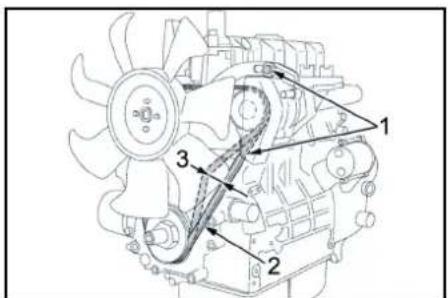
① XapkntaHbpyra aphanraH rehepatopdbI TBib3day 6paHdanaPbI
(2)CbHaJIbI bENJIK
③ BeJik KepeHy iAmamEn 7-9 MM KpaIbI
HycKay
CbHnbl BEnKJ KEmknikmmypde mappBmaca, KcFamkmbl Kblm Kemyi HMece damape dypc 3aprOmanMayb MYMKH.
- KojrantKbIbIeipin, KInT KcokBbHahKInTi anblH3.
2.CbHbBb6EnjIKTHapTbNyBbTHKTECPy yuHb6acbpMaBbHb36eHbENJINHeaHanaTbHTepeuKHTApacbHa6acbHb3.
Hycay
CbHAnbl Bendik wamameh 7-9 MM 6acbinykepK.
Hycay
Opkaaan3aKbimdanraHcbHnB6enokmepoi aybicmbpbHb3.
HepnabkTexeriwiMaJaHb3
1.CaTbIbIMdaBfMaNkbckblbApkblbEkmamNaTbHemIKKeCmKcMaDbkipri3H3.
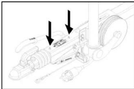
1MaHnaiTbH eMIX
WnHaHbIH KbcbmbHbI TeKcepH3
- KypbIJIbIbIbTeRic 6eTke KOJIbIbIbI3.
- Aya KcbMbHnHeWey KpybIyBcBih LInHaBHnKnahaHa KocbHb3.
- Aya KcbmbMbIh TEKepiH3 («TeXHHaIbIb,DepeKTeP» KaPah3Ib) XOHe KaKet Bonca TyTeHi3I.
Dehrenekti aybictbipbih3
KAYIN
Xa6apnamnap afbHbHa 6aunhaicmbI emIpae Kayin
Koramdknnda xHDey xMblcnapbHxypz3eH Ke3e KpyblrHbI meic femke Koubhla xHe KeiphemH KIM KUH3.
- KypblfnbHb Teric 6etke konbiHb3.
- BetiHIn 6epiTirH TeKecpHIn3. KypBInbIa HnabIn b Tneyni yuiu clyupa karpbi tKepiE 6eHtIn3.
- Typak texkeriuih KynbInTaHbI3.
- WHaHApDbI TeKcepeiH3.
- TnHAnapDbHn DeHreNeKeTp npToeKToPbHnaT Ta3TApDaTKepei3h
- 3aattapdbanbnttactahbl3.
- Tnicti, catbIbMaIbfIuHINaIapIbJxKHeYDe KpyAIIhPiNanDaHaBHy3.
Hycay
Coukec eHdpuyihinYcbihicmapbH opbHdaHB3.0HIM eHpyuici bepaen HcyckaynapobOpbHdacahB3,KeNik kypzdiyjxanractmbpIy MyMKHOiiz3 bOlaB1. UhuanaDbHEmece deeEneKmpeD 6abHwa Jbndam aybcmbpbHb3.
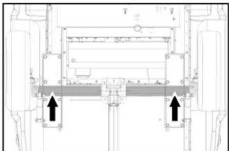
8.ДомКрТынТICTб经ITHe HYKTeHc OphanaTbIpbHbIa3.
9. DeHreNek 6ypaHdAmanapbH 6ocTaHbI3.
10. KypbIINfBnHb IOMKpaT apKnbl KeTepiH3.
11. DeHreNek 6ypaHaJaIapbH 6ypan WbIFapbHb3.
12. Dehrenekti anbin tactaHb3
13. KocankbI DeHreIeKti 6ekitiH3.
14. DeHreNek bpaHdamaIapbIh OPhaTbIbI3.
15. DOMKpaTApKbInbI KypbINfbHbI 6OcA TbIn aNbHb3.
16. DeHTeNek 6ypaHdAmalapbIn kEnIeHeHINHE 6xpaHbIn.
Bypay MOMeHTI
110-120HM
Hycxay
Kemkiy kubihmbiha eWkaHoa domkpm kpmeudi.
Hycay
CamblbMda6apKonaunbdoomkpanmbi nauanaanbHb3.
TipkeMe
- Tekeiyu KypbInhB Mxhe Maacn yakinetti MaanHaDbPbInFaH we6epXaHa YHEm Tekcepin TpybHb3.
Akaynap Ke3iHderi KEmek
KAYIN
KypbInFbHbH 6aikaycbI3da icke KocBnybl
KapaKaam any Kayni, mok cory
KypbiriRbIdarBKe3 KeenZH KyMbIcmapOpbIHdAmac
ObybHn KmKoBbBbBv Ox KyuiHe KousIn, KmN KooBkBbHn AtnIbH3.
KAYIN
Kypbnfkehpyn6bneMepae muin, Keedeocik ickeKobnaad
Kapakam any kayni, mok cory
KypbntfbiaozymbicxacamacOypbH Kypbntfbhb
Keninik uimekepei po3emkaan wibrapbn anbHb3.
KAYIN
Kapibic xhe Kbcka mybikmany Kayni. Bampeera KypandapbHemece conapra Ycac zammapdb KOUImaH3.
1 KypbIfBhlCyblHb3
Ducnnei deri akay
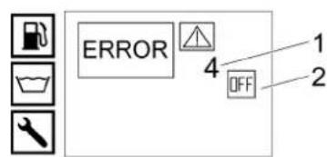
①Kate Hemip
② KozraTknblw eWipnyi (UHIPYII)
TytbHybblnapra Kbi3MeT Kepecy
Aky K0bJIMarH 60nca, uHaCOPfBtBt CepBnCTIK Kbl3MeTTE TeKcepy Kepek.
Ducnnneeri kepcetkiwnen akaynap
| Kate Ce6e6i JxOu JxayantbI | |||
| KATE 1 3aprday tobrI | Желдөтkiштeri сыналы Бeldik керneyi тьмТөмe. | 1.Желдөтkiштeri сыналы Бeldikті кайta tar'tьнБ3. | Операто |
| Жарылдьруа aphanran rehepatorakaylIb. | 1.Жарылдьруа aphanran rehepatoroktepein,камета ayibc'tьрlbn3. | Түлhyшларра КызmetКерсety | |
| Зардay tobrnбakылay куеши eci akaylIb. | 1.Кабельдхларган + K9 penecih Tcekehi3. | Түлhyшларра КызmetКерсety | |
| KATE 3 Cy kipicinH hemece canksyldatuy cybInh Temnttemperatypacbl | Калткы kamepacbaDabry cydln Temnerpatypacbl Tsykln LankpeximHe6aIIanbIbTb MykOarbpbl. | 1.Cydln canklnndaayha MmKmDzik bepiH3 hemece arblybIb3.Шар кранын kaytanay arfaHbHnJ kaxbpatrkduhnybбackapyr mHITPERIN Kozarlanb6aBbIbHa KeIeDeHemOpahtBuH3(500 n). | Операто |
| Су кирсinH Temnerpatya daturri KypilbHbElupdi | 1.KypilbHbIbHbElupin, kajta kocbHbIb3.ЕррakayltbKaytananHcA.TyblHyshlalapra Kby3Met KepcetuyopstanbIbHa XabapnacbIb3. | Операто | |
| Су кирсinH Temnerpatya daturri AkaylIb. | 1.Temnerpatya daturin AybctbIpbHb3. | Түлhyшларра КызmetКерсety | |
| Cankhydattkby cybIbTKbIckdngreYbTbM TemeH. | 1.CanlyndaTbblSy CsybIbTKbIckTbTeHeCTpy bIdbcbHaKiybIb3. | Операто | |
| Жelдөтkiштeri сыналы beldik kergeyi tbrm TemeH. | 1.Жelдөтkiштeri сыналы beldikті kayta tar'tbHb3. | Операто | |
| Kozartkhydattkby canybHdaty cybInh Temnerpatya daturri AkaylIb. | 1.Temnerpatya daturin AybctbIpbHb3. | Түлhyшларра КызmetКерсety | |
| KATE 4 Cy tanbllbbl | Сыrtкы cy berp: cy berp KbyCbMbbl Tbrm TemeH. | 1.Cy berpudi TekcepiH3.Операто | |
| Iliki cy berp: cy barb boc. | 1.Cy barb n Tazalanb3. | Орерато | |
| Kanltyk kamepacdaRbCy tanbllbHbHnKoprakTbHn Kyyieci akaylIb. | 1.Cy tanbllbHbHbHn Koprak y kyyieci n aybctbIpbHb3. | Түлhyшларра КызmetКерсety | |
| CytipiciHderi cyzrl NaactanrH. | 1.Cy kipichderi cyzrliHa taanalanb3. | Орерато | |
| Czy shanrlici TbyIb3 emec Hemece MbaylcBnKaalr. | 1.Cy shanrlici aybctbIpbHb3. | Түлhyшларра КызmetКерсety | |
| Kanltyk kamepacdaRbBdBy kalykbHbbl Knaanahn NaactanrH. | 1.KanltybNl kanaanDbIb TaZanalanb3. | Түлhyшларра КызmetKерсety | |
| Kanltyk kamepacdaRbBdBy kalykbHbbl Knaanahn Kentenlin kailblbHemec aKaylIb. | 1.KanltybNl kanaanDbIb TaZanalanb3 Hemece aybctbIpbHb3. | Түлhyшларра КызmetKерсety | |
| KATE 5 Abyin Kockbblb/Кысын Temckbbl | Abyin Kockbblb akaylIb. | 1.Abyin Kockbblb aybctbIpbHb3. | Түлhyшларра КызmetKерсety |
| KbIcIM Kockbblb akaylIb. | 1.KbIcIM Kockbblb aybctbIpbHb3. | Түлhyшларра КызmetKерсety | |
| Kaiita etkizy Klananblb akaylIb. | 1.Kaiita etkizy Klananblb aybctbIpbHb3. | Түлhyшларра КызmetKерсety | |
| Kaiita etkizy Klananbldabl kerip coKkblk Klananblb akaylIb. | 1.Kei p coKkblk Klananblb aybctbIpbHb3. | Түлhyшларра КызmetKерсety | |
| Coprbln andin ana Tazalanay cyarici naactanrH. | 1.Coprbln andin ana Tazalanay cyarici n TazalanBn. | Орерато | |
| Бу ржим: куVE KBcMbbl Tbrm TemeH. | 1.Kaia t eKizy Klananblb NytKacbHn caraf TtinHn BafblmEn b6papan, kvyE KcMbbln a3daran Kaadamdpem KetepiH3. | Орерато | |
| KATE 6 Khanapmaat daturir | ЖанармадBarb6boc. | 1.Жанармад Кkyo. | Орерато |
| Жанармад daturirHin KaTbKbIbCbl Kcblbln KaIbIb. | 1.KanlkbHbTeKcepiH3. | Түлhyшларра КызmetKерсety | |
| Жанармад daturir AkaylIb. | 1.Жанармад daturirn AybctbIpbHb3. | Түлhyшларра КызmetKерсety | |
| KATE 9"Падаланынraя temperatypacbl | Падаланынraя raz TemnerpatypacbHn Shekterii Icke KocbIbIb Jxane He JozanapfBhlb ewipid. | 1.KypilbHbEl uqipin, cybIbHbI3 xOHe Kaitya KocbHb3. Erep akaylIbK kaytananHcA.TyblHyshlalapra Kby3Met Kepcetuy opTalbblHa xabapnacHb3. | Орерато |
| Падаланынraя raz TemnerpatypacbHn Shekterii Icke AkaylIb. | 1.Падаланынraя raz TemnerpatypacbHn ShekteriiHn aybctbIpbHb3. | Түлhyшларра КызmetKерсety | |
| Жанаргы дурс орналmarаган. | 1.Жанаргы oрналmarragan | Түлhyшларра КызmetKерсety | |
| Жын litуч epktyTiri ryigren Hemece kaKhen JxabIbflan. | 1.Жын litуч epktyTiri ryigren Kvy Hemece KaTb KtepiH3. | Түлhyшларра КызmetKерсety | |
| KATE 10"Жанаргы Temperatypacbl | Жанаргын Temperatypa daqurri (NTC)Жанаргын ewipid. | 1.KypilbHbEl uqipin, kaitya kocbHbIb. Erep akayltbK kaytananHcA.TyblHyshlalapra Kby3Met Kepcetuy opTalbblHa xabapnacHb3. | Орерато |
| Жанаргын Temperatypa daqurri akaylIb. | 1.Temnerpatya daturirn aybctbIpbHb3. | Түлhyшларра КызmetKерсety | |
| Kate | Cse6e6i | Жою | Жayantы |
| KATE 11*Жалын Datчuri (жалын жк) Сык сунen тазалay рechимь solуы муMKIN. | СаNTama Tаяры Лостанган. | 1.СаNTama Tаярын Тазалань. | Тусыншыларра Кызmet керсETY |
| Тусынуfa aphanfahн зilektrodkтар дурьс орнатулмаган Неме салдан. | 1.Тусынуfa aphanfahн зilektrodkтардурьс орнатулбил hemece Тазалань. | Тусыншыларра Кызmet керсETY | |
| Жалынды Баслай жүүсінфотоэменті akayпь. | 1.ФOTOЗЕМЕHTI aybICTbIPbHbI3. | Тусыншыларра Кызmet керсETY | |
| Жанармай сорfcbсы akayпь. | 1.Жанармай сорfcbсы aybICTbIPbHbI3. | Тусыншыларра Кызmet керсETY | |
| Жанармай зilektprmaŋHTTik Клanaны Akayпь. | 1.ЗilektprmaŋHTTik Клanaныды aybICTbIPbHbI3. | Тусыншыларра Кызmet керсETY | |
| Осын суз Rici bitelenin калдь. | 1.Осын суз Rici n aybICTbIPbHbI3. | Тусыншыларра Кызmet керсETY | |
| Жогары керney trancfopomatobу akayпь. | 1.Жогары керney trancfopomatobu n aybICTbIPbHbI3. | Тусыншыларра Кызmet керсETY | |
| KATE 12*Жалын Datчuri (жалын сенид) Сык сунen тazалay рechимь solуы муMKIN. | Жалынды Баслай жүүсінн Фотоэlementti akayпь. | 1.ФOTOЗЕМЕHTI aybICTbIPbHbI3. | Тусыншыларра Кызmet керсETY |
| Жанарь Күйгэн, odan keihn «жарksырады. | 1.Жанарь Күйгэн Тазалань И муMKINdik δерiN3. | Тусыншыларра Кызmet керсETY | |
| KATE 14 45 Минут уздікіз 3 y3lnictehen кейнewsipy | КУту уakытBu 45 минутан acын KeTTI. | 1.КурьнгынБ ewilipin, kaitya KocbHbI3. | Опepatop |
| KATE 15 45 Минут уздікіз 3жymыстан кейнewsipy | Чздікіз жүmbic 45 минутан acын KeTTI. | 1.ЧурьнгынБ ewilipin, kaitya KocbHbI3. | Опepatop |
Dncnnei3 akaynbikTapdbj koo
| Kate | C6e6i | Жою | Жayantы |
| Курлы村村民 | Сашийы Кшш калл. | 1.Сашийы Кшш Калл. | Оператор |
| Баразец Кшш Тамен Калл. | 1.Баразец Кшш Калл. | Оператор | |
| Баразец Кшш Калл. | 1.Баразец Кшш Калл. | Оператор | |
| Тергейш Калл. | 1.Тергейш Калл. | Туltиушдограда Кызмета КерсETY | |
| Тергейш Калл. | 1.Тергейш Калл. | Туltиушдограда Кызмета КерсETY | |
| Косылган呐 сон диспел жок | Баразец Зарды тayсылган. | 1.Баразец Зарды тayсылган. | Оператор |
| Сашийы Зарды жанылган. | 1.Сашийы Zарды тayсылган. | Оператор | |
| Албийы Хankьш рш. | 1.Албийы Хankьш рш. | Оператор | |
| Жedел ewipriш баслган. | 1.Жedел ewipriштariу apkblыкш рш. | Оператор | |
| Баразец Кшш Тамен Калл. | 1.Баразец Кшш Калл. | Оператор | |
| Тергейш Калл. | 1.Тергейш Калл. | Туltиушдограда Кызmetа КерсETY | |
| Козаглты Косылмайы Немес бiderен ewin калды | Туltиушдограды Калду Кызmete хабарлы. | ||
| Жуmbic Kысы Мы овлды | Жуары Кысы Мы сорыны кібepy жолында arыл кету. | 1.Кубл对接 ecinTekcepiniz3. | Туltиушдограда Кызmetа КерсETY |
| Кланандар тordан. | 1.Кланандары убл对接 bnyts. | Туltиушдограда Кызmeta КерсETY | |
| Жанарлы Күйелigiz | Жанары Дурьс opнылмаган Немес Тадановогan. | 1.Жанары Кызындяпз hemesе тазаланы. | Туltиушдограда Кызmeta КерсETY |
| Жанарм Злakромагниттik Каланы akaylnы, дizilelдik otbilly tamshilan Typ. | 1.Злakромагниттik Каланыдяпсэринл заун Каланыдьс.Tур. | Туltиушдограда Кызmeta КерсETY | |
| Жанарлыдан shылдан ak тутIN | Тутanyу shылды жok (Жанары Каллары мандaiэйнкетен керин). | 1.Туltиушдограды Калду Кызmete хабарлы. | Оператор |
| Сатума Таяндагы Кondencat cy. | 1.Сатума Таяндагы Тссерin, Тадаланы. | Туltиушдограда Кызmeta КерсETY | |
| Жанарм Кысы Мы Тьм Temen. | 1.Жанарм Рсгьсын Tekcepiniz3. | Туltиушдограда Кызmeta КерсETY | |
| Алдынгы_Jжankьш/anaattык ewipry бakылay shamы ожанды | Жумьс Барыбindу щдды Jжankьш ашылды. | 1.Алдынгы_Jжankьшдy Jжankьш. | Оператор |
| Алдынгы_Jжankьштih Kajincdik Kockblits ашылды. | 1.Кajincdik Kockblitsн Tekcepiniz3. | Туltиушдограда Кызmeta КерсETY | |
| Жedel ewipriш baskylarhan. | 1.Жedel ewipriштariу apkblын Күлннштir. | Оператор | |
| Курлыгын Tубihan су Tamshilды | Жогары Кысы Мы соры Тыгьз emec. | Hускay: Мнунова 3 tamшлга рухсан etinei. Тыгьздьгь осыдан azaday Быногду Туltиушдограда Кызmet КерсETYМерсету Мамандагы apkblы Tekcepintin albhyl. | Туltиушдограда Кызmeta КерсETY |
| Курлыгы eschan'day Кысыл хасамады | Сатума Бітелген/Жулган. | 1.Сатумаларды тazanlanbɪs/aybctlbpyhɪs3. | Туltиушдограда Кызmeta КерсETY |
| Кozraill'tkshtBnJxmybc cahby eTe Tmeh. | 1.Кozraill'tkshtBnJxmybc Jxmybc JxlldAmdbfBnJ | Туltиушдограда Кызmeta КерсETY | |
| Тун HDS 9/50, HDS 13/35 (HDS 13/20, HDS 17/20 ушп кocьшima):Жылдамыктby басару akayln. | 1.Жылдамыктby baskapdyts Tekcepiniz3. | Туltиушдограда Кызmeta КерсETY | |
| Кayincdik каланы Тыгьз emec. | 1.Оратуды Тссерiniz3Жаhe, калет solona, кана Тыгьздьгь орату bryts Tekcepintin albhyl. | Туltиушдограда Кызmeta КерсETY | |
| СорыштВнКosity Кысылрары abfinжаар нemessе велллк. | 1.CorрыштВнКosity Кысылрары bryts Tekcepintin | Туltиушдограда Кызmeta КерсETY | |
| Жогары Кысыдьс coprfl сырлдды | СорыштВнКosity Кысылрары abfinжаар нemessе велллк. | CoprllshTnKoscy KusbpapnablnbH baryn Tekcepiniz3. | Туltиушдограда Кызmeta КерсETY |
| Kate | Ceb6bi | Жою | Жayantы |
| Tek HDS 13/20, HDS 17/20:Жулыкалды 6еру жетkinikciz hemece кok | Таразалу куралын мелшерney кланыхжавьк hemece arын/бileтген | 1. Таразалу Куралын мелшерney кланын ausын hemece tekspin/tazaan an albyhiz. | Оператop |
| Суэрici бар тазалу куралын copyшалнigri arын котыр hemece 6iteллkan raftan | 1. Суэрici bap тазалу Куралын copyшалнigri tekspin/tazaan an albyhiz. | Оператop | |
| Жулыкалды эльекрмагнittik кланыхарыхжatableнореме 6iteллkan raftan. | 1. Куралыкалды эльекрмагнittik кланын tekspin, tazaananiz. | Тулыншалрра КызmetКерсety | |
| Злеслонык мени Куралын злеслолдын khalanыхakaylly. | 1. Злеслонык мени Куралын злеслолдын tekspin, tazaananiz. | Тулыншалрра КызmetКерсety | |
| Кол bypіkkii пистоletіашик 6bonган KEЗDE кайта оtki3у кланын уздіксіз aшылады/жавьndы | Cantrama 6iteлген. | 1. Cantramaalap'da Таразалу. | Оператop |
| Курында тат пада 6oinder. | 1. Курында кальтан Tazap'tbHiz. | Тулыншалрра КызmetКерсety | |
| Кайта оtki3у кланын akaylly. | 1. Кайта оtki3у кланын akaylly. | Тулыншалрра КызmetKерсety | |
| Кайта оtki3у кланын bihnyн acbycу hykteci peTTendi. | 1. Кайта оtki3у кланын peTTendi. | Тулыншалрра КызmetKерсety | |
| WR KоралшасьнIH 6akblay y shambl KBiz3bI TycTe xanadbl | Бу рeshим!Жу ue Кысьмbl Tblm Xorapbl | Кайта оtki3у Кланын bihн Тукасьн caraf TizHe Kapcsblбурал,Жу ue Кысьмbl a3da farah Ka daMdapMeHТemehdetihi3. | Оператop |
Keninaki
Op enJeKeprinikTnDcTnpiBToTnpA6peRhen Keinnik
IapTTapbKoJdaHbNabMb. ByIMDa MaTePnAnDbk
HeMece HeHIpicTik Aayapnay aHbTkTaFnaH KafdAa,
BkTmamakaynapdbKeiINiik Mep3imi iuHne AkbCb
XeHneMIm. Keniink Mep3imHe HapaBbIKTapbHb3
60Na, 6yBIMDbCaTkaH caJa DMekeMeCHe He Mece
XaHnHaar bEknETt Kb3Met KepCteY opHbHa
Ty6pTeKTKe pceretin Xa6apnacbHb3.
(MeKeHkaBbM3 apKb6eTte)
KeniinkTypaBkoCboIMMa aknapattb (6ap 60Na)
KeprinikTi Karcher Be6-caNTbHIn *XkyTeynep
BeIMiHer Kz3Met KepCteY beIMiHde Ta6yfa
60Na,b.
UbIfary KyHi FmPmAbK TAKtaWada MM/YYY
NiIMiHe KepeCtineDi MyHaMM- eHdpicA,b, YYYYY
- UbIapbIraH XblbHE Meces KoTaNanr Tpyde.
Keke caHaapdbH MaBhAcb KeleciDe BoNa;
MbCanb: 30290
3 OHeipinre Hxblb
OHeipinre RaCbpbl
2 OHeipinre OHkblbIK
9 OHeipinre AByHbH EkiHsi caHb
O Heipinre AByHbH BipHsi caHb
CoHbMeH 6yN MbCanda 30290 KOnb09/(2)023
eHdpinre KynH Binipei.
Kypan-Xa6dbikTap MeH Kocajkb6eJweKeTep
Hycay
Kypblfki KAMHee KocBnfah 60nca HEmecE Kypflbfk KopH6eumih Bonla,613 KanbH damuuzin (Kocbmu) opAhmyoYcBHaMbI.
Te TynHcyakbnKepeKkapA Hemece KocanBb 6bnuekeptnainananaHbH3,ce6e0nKpandbH kayincs Xane anatcb3 Kymblc icteyihKeinilik 6bnabl.
Kepek-kaapakapt men KocanbI b6eueKTeP typabI kApnapaWww.kaercher.com Be6-caTbHnda KOJkeTImI.
EO cTAndapTTapbHa cEKeCtiI TpyaBJI dKnapaun
OcMbHMe TEmHeKePcTeINrReMaMHaKayIncIzIK
KHe DeHCaybIK Kpoy 6oBHHa EO
DnEeKTHBanapbHtN TaanTApBaHc KaNEc KeNETiHi
MAnIMDeHm3. B36EH KenICyciMaHNHaBH
KOHCTpyuHcBcB3repReH XaFdaJDa OCb DeKnapaun
E3 KyuH JKOJIb.
BybIM: XJorapBb KbcMbbl JxbyIi Tuni: 1.524-xxx Tuni: 1.999-380.0
KoJaDaHbIcTaFbE OINeKTeNbAnabpIb 2006/42/EG(+2009/127/EG)
2000/14/EG
2014/30/EU
2014/68/EO (KocbIMua)
KoIaHbIaTbH 6ip3eHdipinre h cTaHapTtap
EN 60335-1
EN 60335-2-79
EN 1829-1
EN 1829-2
EN ISO 12100
EN 13309:2010
EN 55012:2007+A1:2009
EN 62233:2008
CaikeTikke KOndaHbInaTbIn TeKcepy aDici
2000/14/EC:V KocbIMwacbl
Yb6bc KyaTbHbHbHbH deHreJdB(A)
HD 9/23 GeTr1 + HD 9/23 DeTr1
OuheHai:105
Keninik 6epei:107
HDS 13/20 DeTr1
OuueHni:97
Keninik 6pepi:100
HDS 13/35 DeTr1 + HDS 9/50 DeTr1
Elnwehdi:100
Kenjinik bepeni: 102
HDS 17/20 [
Oeunendi:100
Keninik 6epei:102
KOCbIMUA
Ohim: ABS 6vHDS 1000
Tunl:2.013-093.0
KypacTbIpy caHaTbI
Caikectik npoceypacbl
H1 moyni
Xbunbity npektytiri
Caikectikti 6afanay, H1 modyni
Backapy 6norbl
Caikectikri 6aranay, H1 moyni
@ptpni ky6bip jeninepi
Chairman of the Board of Management
S. Reiser
Manager Regulatory Affairs & Certification
KykaTamaHbI Kypri3eIH yakinettiynra
C. Pau3ep
Alfred Kärcher SE & Co. KG
Alfred-Karcher-Str. 28 - 40
71364 Winnenden (Германя)
Ten: +49 7195 14-0
Tepeka: +49 7195 14-2212
Winnenden, 2023/01/01
TexHnKanblk MaflnyMaTTap
| HDS 9/50 DE Tr1 | HDS 13/35 DE Tr1 | HDS 13/20 DE Tr1 | HDS 17/20 DE Tr1 | ||
| Сydлы косу | |||||
| ЕнглStyletemпературасы (мак.) | °C | 30 | 30 | 30 | 30 |
| ЕнглStyle саны (Min.) | I/h (I/min) | 1000 (16,7) | 1500 (25) | 1500 (25) | 1800 (30) |
| ЕнглStyle Кльсьмы (мак.) | MPa (bar) | 0,05-1 (0,5-10) | 0,1-1 (1-10) | 0,1-1 (1-10) | 0,15-1 (1,5-10) |
| Кублгын Textнокалык сидаимаары | |||||
| Берілтін мени侨,сy | I/h (I/min) | 500-900 (8,3-15) | 650-1300 (10,8-21,7) | 900-1300 (15-21,7) | 900-1700 (15-28,3) |
| Стондіріті саітамась бар жүміс Кьісьмінідірісy | MPa (bar) | 15-50 (150-500) | 10-35 (100-350) | 6-20 (60-200) | 6-20 (60-200) |
| Артык жүміс Кьісьміні саітанідіріьші Кләпаны (мак.) | MPa (bar) | 64 (640) | 44 (440) | 24 (240) | 24 (240) |
| Бүмін жүміс ICTey ушін Бері кьілдімідіріs | I/h (I/min) | -- | -- | 460 (7,7) | 460 (7,7) |
| Бүмін жүміс ICTey ушін Бері кьілдімідірін Deэзнфекцяялay | I/h (I/min) | -- | -- | WR 10, WR 20: 360(6)WR 50, WR 100: 460(7,7) | WR 10, WR 20: 360(6)WR 50, WR 100: 460(7,7) |
| Бүмін саітамась apсыы bүмін жүміс кеін'deri жүміс Кьісьміы (мак.) | MPa (bar) | -- | -- | 3,2 (32) | 3,2 (32) |
| Бүлшік № Бүмін тазаалayga arpanlган 6by саітамась (саітамаелші) | -- | -- | -- | 2.113-026.0 (060) | 2.113-026.0 (060) |
| Бүлшік № Deэзнфекцяялay keizdleri 6by саітамась (саітамаелші) | -- | -- | -- | WR 10, WR 20:2.113-022.0 (045)WR 50, WR 100:2.113- 026.0 (060) | WR 10, WR 20:2.113-022.0 (045)WR 50, WR 100:2.113- 026.0 (060) |
| Коштankьш куаты kW 15,5 15 9 11 | |||||
| Коштankьш Кубдамбгы | 1/min | 3100 | 3300 | 2700 | 3300 |
| Багараз V/Ah 12/41 12/41 12/41 12/41 | |||||
| ысты с Dynamухумб Температурасы (Мakс.) | °C | 30-98 | 30-98 | 30-98 | 30-98 |
| Бу ржимин Хуши Семпературасы | °C | -- | -- | 155 | 155 |
| Беріnettін мениці, Ку? Бу? Бу? Бу? Бу? Бу? Бу? Бу? Бу? Бу? Бу? Бу? Бу? Бу? Бу? Бу? Бу? Бу? Бу? Бу? Бу? Бу? Бу? Бу? Бу? Бу? Бу? Бу? Бу? Бу? Бу? Бу? Бу? Бу? Би? Бу? Бу? Бу? Бу? Бу? Бу? Бу? Бу? Бу? Бу? Бу? Бу? Бу? Бу? Бу? Бу? Бу? Бу? Бу? Бу? Бу? Бу? Бу? Бу? Бу? Бу? Бу? Бу? Бу? Бу? Бу? Бу? Бу? Бу? Бу? Бу? Бу? Бу? Бу? Бу? Бу? Бу? Бу? Бу? Бу? Бу? Бу? Бу? Бу? Бу? Бу? Бу? Бу? Бу? Бу? Бу? Бу? Бу? Бу? Бу? Бу? Бу? Бу? Бу? Бу? Бу? B Б Б Б Б Б Б Б Б Б Б Б Б Б Б Б Б Б Б Б Б Б Б Б Б Б Б Б Б Б Б Б Б Б Б Б Б Б Б Б Б Б Б Б Б Б Б Б Б Б Б B B B B B B B B B B B B B B B B B B B B B B B B B B B B B B B B B B B B B B B B B B B B B B B B B B C C C C C C C C C C C C C C C C C C C C C C C C C C C C C C C C C C C C C C C C C C C C C C C C C C B B B B B B B B B B B B B B B B B B B B B B B B B B B B B B B B B B B B B B B B B B B B B B B B B Eлш: Флш: Флш: Флш: Флш: Флш: Флш: Флш: Флш: Флш: Флш: Флш: Флш: Флш: Флш: Флш: Флш: Флш: Флш: Флш: Флш: Флш: Флш: Флш: Флш: Флш: Φлш: Φлш: Φлш: Φлш: Φлш: Φлш: Φлш: Φлш: Φлш: Φлш: Φлш: Φлш: Φлш: Φлш: Φлш: Φлш: Φлш: Φлш: Φлш: Φлш: Φлш: Φлш: Φлш: Φлш: Φлш: Флш: Флш: Флш: Флш: Флш: Флш: Флш: Флш: Флш: Флш: Флш: Флш: Флш: Флш: Флш: Флш: Флш: Флш: Флш: Флш: Флш: Флш: Флш: Флш: Ft Ft Ft Ft Ft Ft Ft Ft Ft Ft Ft Ft Ft Ft Ft Ft Ft Ft Ft Ft Ft Ft Ft Ft Ft Ft Ft Ft Ft Ft Ft Ft Ft Ft Eлш: Флш: Флш: Флш: Флш: Флш: Флш: Флш: Флш: Флш: Флш: Флш: Флш: Флш: Флш: Флш: Флш: Флш: Флш: Флш: Флш: Флш: Флш: Флш: Флش: Флш: Флш: Флш: Флш: Флш: Флш: Флш: Флш: Флш: Флш: Флш: Флш: Флш: Флш: Флш: Флш: Флш: Флш: Флш: Флш: Флш: Флш: Флш: Флш: Флش: Φлш: Φлш: Φлш: Φлш: Φлш: Φлш: Φлш: Φлш: Φлш: Φлш: Φлш: Φлш: Φлш: Φлш: Φлш: Φлш: Φлш: Φлш: Φлш: Φлш: Φлш: Φлш: Φлш: Φлш: Φлش: Φлш: Φлш: Φлш: Φлш: Φлш: Φлш: Φлш: Φлш: Φлш: Φлш: Φлш: Φлш: Φлш: Φлш: Φлш: Φлш: Φлш: Φлш: Φлш: Φлш: Φлш: Φлш: Φлш: Φлш: Флش: Флш: Флш: Флш: Флш: Флш: Флш: Флш: Флш: Флш: Флш: Флш: Флш: Флш: Флш: Флш: Флш: Флш: Флш: Флш: Флш: Флш: Флш: Флш: Φлш: Φлش: Φлш: Φлш: Φлш: Φлш: Φлш: Φлш: Φлш: Φлш: Φлш: Φлш: Φлш: Φлш: Φлш: Φлш: Φлш: Φлш: Φлш: Φлш: Φлш: Φлш: Φлш: Φлш: Флш: Флш: Φлш: Φлш: Φлш: Φлш: Φлш: Φлш: Φлш: Φлш: Φлш: Φлш: Φлш: Φлш: Φлш: Φлш: Φлш: Φлш: Φлш: Φлш: Φлш: Φлш: Φлш: Φлш: Флш: Флш: Φлش: Φлш: Φлш: Φлш: Φлш: Φлш: Φлш: Φлш: Φлш: Φлш: Φлш: Φлш: Φлш: Φлш: Φлш: Φлш: Φлш: Φлш: Φлш: Φлш: Φлш: Φлш: Φлш: Φлш: Флш: Флش: Флш: Флш: Флш: Флш: Флш: Флш: Флш: Флш: Флш: Флш: Флш: Флш: Флш: Флш: Флш: Флш: Флш: Флш: Флш: Флш: Флш: Флш: Φлш: Φлш: Φлش: Φлш: Φлш: Φлш: Φлш: Φлш: Φлш: Φлш: Φлш: Φлш: Φлш: Φлш: Φлш: Φлш: Φлш: Φлш: Φлш: Φлш: Φлш: Φлш: Φлш: Φлш: Флш: Флш: Флш: Флش: Φлш: Φлш: Φлш: Φлш: Φлш: Φлш: Φлш: Φлш: Φлш: Φлш: Φлш: Φлш: Φлш: Φлш: Φлш: Φлш: Φлш: Φлш: Φлш: Φлш: Флш: Флш: Флш: Флш: Флش: Флш: Флш: Флш: Флш: Флш: Флш: Флш: Флш: Флш: Флш: Флш: Флш: Флш: Флш: Флш: Флш: Флш: Флш: Флш: Φлш: Φлш: Φлш: Φлш: Φлш: Φлش: Φлш: Φлш: Φлш: Φлш: Φлш: Φлш: Φлш: Φлш: Φлш: Φлш: Φлш: Φлш: Φлш: Φлш: Φлш: Φлш: Φлш: Φлш: Флш: Флш: Флш: Флш: Флш: Флш: Флش: Флش: Флش: Флش: Флش: Флش: Флش: Флش: Флش: Флش: Флش: Флش: Флش: Флش: Флش: Флش: Флش: Флش: Флش: Флش: Флش: Флش: Флش: Флش: Флش: Флш: Флش: Флش: Флش: Флش: Флش: Флش: Флش: Флش: Флش: Флش: Флش: Флش: Флش: Флش: Флش: Флش: Флش: Флش: Флش: Флش: Флش: Флش: Флش: Флш: Флш: Флش: Флش: Флش: Флش: Флش: Флش: Флش: Флش: Флش: Флش: Флش: Флش: Флش: Флش: Флش: Флش: Флش: Флش: Флش: Флش: Флش: Флش: Флш: Флش: Флш: Флش: Флش: Флش: Флش: Флش: Флش: Флش: Флش: Флش: Флش: Флش: Флش: Флش: Флش: Флش: Флش: Флش: Флش: Флش: Флش: Флش: Флش: Фл" Фл" Ф" Ф" Ф" Ф" Ф" Ф" Ф" Ф" Ф" Ф" Ф" Ф" Ф" Ф" Ф" Ф" Ф" Ф" Ф" Ф" Ф" Ф" Ф" Ф" Ф" Ф" Ф" Ф" Ф" Ф" Ф" Ф" Ф" Ф _ Ф _ Ф _ Ф _ Ф _ Ф _ Ф _ Ф _ Ф _ Ф _ Ф _ Ф _ Ф _ Ф _ Ф _ Ф _ Ф _ Ф _ Ф _ Ф _ Ф _ Ф _ Ф _ Ф _ Ф _ Ф - Ф - Ф - Ф - Ф - Ф - Ф - Ф - Ф - Ф - Ф - Ф - Ф - Ф - Ф - Ф - Ф - Ф - Ф - Ф - Ф - Ф - Ф - Ф - Ф - Ф _ Ф _ Ф _ Ф _ Ф _ Ф _ Ф _ Ф _ Ф _ Ф _ Ф _ Ф _ Ф _ Ф _ Ф _ Ф _ Ф _ Ф _ Ф _ Ф _ Ф _ Ф _ Ф _ Ф _ Ft Ft Ft Ft Ft Ft Ft Ft Ft Ft Ft Ft Ft Ft Ft Ft Ft Ft Ft Ft Ft Ft Ft Ft Ft Ft Ft Ft Ft Ft Ft Ft Ft | |||||
| Жу? Жу? Жу? Жу? Жу? Жу? Жу? Жу? Жу? Жу? Жу? Жу? Жу? Жу? Жу? Жу? Жу? Жу? Жу? Жу? Жу? Жу? Жу? Жу? Жу? Жу? Жу? Жу? Жу? Жу? Жу? Жу? Жу? Жу? JL JL JL JL JL JL JL JL JL JL JL JL JL JL JL JL JL JL JL JL JL JL JL JL JL JL JL JL JL JL JL JL JL JL Z | |||||
(EO) 2019/1781 KocbIMwacbHa CnKeC anIn Tactay
ce6e6i 2-6enim (12):j)
TexHKaIbIK e3repicTepeHri3iNyIMMKIH.
.000000000000000000000000000000000000000
aaabjJ1110cglgll aueaubw
cagll jao jalall qswj < Jaiuall aagg alssj
a>gall a201
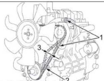
aalll JbUul 1 aJg aJg
aIeall 1
.0JUwI gOjpo1u2awU jgJgJg
.
a>all
a.bu>Ua2eulwJp
aalll
.6JusllgolpdoLdssuJgljJl
Jlalal alal
110-120
.0JLsJgEgJgJgJgJgJgJgJgJgJgJgJgJgJgJgJgJgJgJgJgJgJgJgJgJgJgJgJgJgJgJgJgJgJgJgJgJgJgJgJgJgJgJgJgJgJgJgJgJgJgJg
jgluo wlo oJw gJgpo aBgdo
gU
0gbaoo
aJg jn qjglll p2ig Jolajll pblj
p2uo Jiu oiao
Jllacj cie oedwll
在 Rt ABD 中:
jai jia 11011 Jauu
cllaallwogclaaJasilljll
ab > 0
5182905 1aillp5 aeeoo 6b01c0d
Jeuill sIg Juiu 1oo ic uoe el
S = 12 · ( r1^2 + r2^2 + r3^2)
Jc qilb 100/100/100/100/100
ylll//ll0gog g/129
jglj j
Jusaw
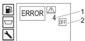
(OFF)JJJ
alloss
J 1
1 1
a>gall 2
9-7 3
J K J 100
aLAsgJzaljOjIg aJgElaJI JdS
aB
clll jssjjj 1000
Jyssllbcbaol,ggallsw
pUgUyUyUyUy
J 1
aill 1jia jaiil Jolal paa a
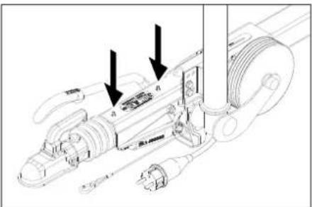
(gul)uuiu 1e auiuog u
gao 2w wu wu sl
1JbUcglafoa
aagwaaoojLc jgaiypa
paalbulgbao jagjogui
JU
sic baiial aagog algel laeiaa e
.9j山
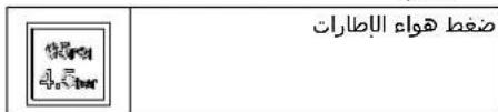
aBaaJ
k2 ≤
a 9 aee
103, 104, 105, 106
aagaaoJcJgJgJgJgJg
Ug U>
palauiu jaiil wj jglal aol o
1
11111
aai 2g> C a0 jIbU baw a>J, p
a. aEa
LwUaJIjP
algaiogawoliojulblaow
.
wJgBwgl wjll gss
J
←
Jwgl JwJll
aio 80sLoisLwO wJl gss
C. a b c d e
←
CjogJal axiabc jn
W
<.
:
.
aaiial aiaolgai jbi i jj
Jlll lalaii aaiy jlls
wJlsl
HDS 13/35 g HDS 9/50
Iaiaaiiaaiiuiuuiyjusgaae
JL
MAX9MINaol
jN MIN aolc no jBj wJgssn 13
j> c0cJog c0jll j> elao
cui j1s elao glc
:
.
aaiiaaaalalalalalalalalalalal
jzai jia jia jia jia jia jia jia jia jia jia jia jia jia jia jia jia jia jia jia jia jia jia jia jia jia jia jia jia jia jia jia jia jia jia jia jia jia jia jia jia jia jia jia jia jia jia jia jia
olclgogoslosjllss
a aaii iie oia aaioi 05
wagac JzJgall ayas no gglUll .Jall axiig ciae glg wjj
Jl 1 J 1 1 1 1 1 1 1 1 1 1 1 1 1 1 1 1 1 1
aiaaull gUul jdlal aabii
J 1
aJall JlscI
Laeial no jglg 8a
g 1/2 1/2 1/2 1/2 1/2 1/2 1/2 1/2
123
124
125
126
aLw logf gj/ajgai U!laia 1
1.11111111111111111111111111
olall Jdabbi
WJ .
IIN . .
aBll ola looogb jol qabu
aBll ola looogb jol glal lcl a 1
aBll a2g lc.aBll ola looogb jzj 1
sJ 0y aS p clall jilall aBtu
g jll g jll j j j j j j j j j j j j j j j j j j j j j j j j j j j j j j j j j j j j j j j j j j
aolll oic 1,6 aas gl :Lj .s sss , wao Lac . MAX g MIN
oogolgolgulwolp,cjlluogac
a aal lal ylll baiall pgoj Jog
gall aIalgl baxclal gbsj
oslo uls gacall no aIal Jilw ia
oIaIe all bax gacall no aIaI
asaiall slll lagg gacall no aIaI
plssuL gacall no aIalall oslo jz jao
JU pJls aialgog glgwl
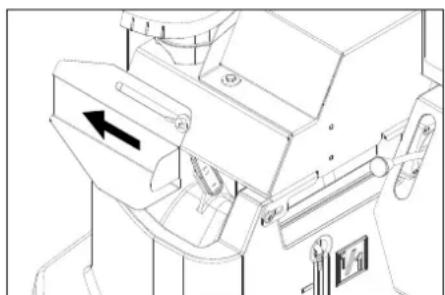
g j 1 g aolgll 1j 20 20
Jall aal glg
Jol gaoa
o aiaa ola o 20 Jo
Jall aag glc p aolgl
o aiaa ola sgsll plaaa Jgswg J
. Jll Jgswg Jgswg
Eg Jgswg Jgswg Jgswg
.(J20) Jgwl g sglll
:Laq Jll Jx
Jauwll ciao oJd | y, Laae uol
Zuaa aaiy Jdaa WUg Jauu J
qasall nssall p
Woo ."I, Gogll JI Jaaa OJ]
Jewill dawll Pk
Jt> awll jro g axil g Jzwi
."
J
. 50 a j 50 .
aibill oslo piai y
HDS 17/20 g HDS 13/20 J bα9
"0, a>JUJI le c auiuill oJoo plao uoi Ue Iaui jUJI le oJg aaij Jauu Juaei Ue Gaa
jgl
125 A
U 125 U 125
U 125 U 125
U 125 U 125
U 125 U 125
U 125 U 125
U 125 U 125
U 125 U 125
U 125 U 125
U 125 U 125
U 125 U 125
csc lueic jzai/ 10e / 1jwol / g2j, jbs
sw// wuuu csc loucg aolcl / alga//
.
105-85 105-85
J
J
J
J
J
J
J
J
J
J
J
J
J
J
J
J
J
J
J
J
J
J
J
J
J
J
J
J
J
J
J
J
J
J
J
J
J
J
J
J
J
J
J
J
J
J
J
J
J
J
J
J
J
J
J
J
J
J
J
J
J
J
J
J
J
J
J
J
J
J
J
J
J
J
J
J
J
J
J
J
J
J
J
J
J
J
J
J
J
J
J
J
J
J
J
J
J
J
J
J
(aagjlll)jllg
()HDS17/20gHDS13/20J 电 aegaoaoljglgagwlllalwlaI gaaallnjL)acuulplola!o!(2.013014.0:>U acgaoo,2.013086.7
JbA Jueuill bao jglu jguy U,ggy Auolll Jbs oJyI aOgSc loic (jL 32) Jscwleo 3.2 .aioo105,oo,cl
sucurj 1xuul yuuiu
wJyawLiojzaggJl:JuUyabuWl (ailluljbi aalllp) wJl Ue 100 gI WR 10,20,50 wJ:aaill Jbi .aalall p) awliagg pduuWjI (aillul
"Jgog" Jgog Jgog Jgog Jgog Jgog Jgog Jgog Jgog Jgog Jgog Jgog Jgog Jgog Jgog Jgog Jgog Jgog Jgog Jgog Jgog Jgog Jgog Jgog Jgog Jgog Jgog Jgog Jgog Jgog Jgog Jgog Jgog Jgog Jgog
J 30 JJIaJIJI WJAIJIgAclll JIJI
J>Uj plalgl sgl l j 1j< 1gll jnoll p> .sgl l wjl
Jzjwll 0j> a> Jl Jgwsj:Jzj J4-2 Jg> .aasll gJr JbU bU pUu < :aollll lbbg
UJUL e WRR-Box gddy y sll 1
aagg gblal algl gjo alal Iabio j> U
JIbACUI ic ocll al bai
Ibio:pszil a>gl aywll JERROR5 2
jai jai Jia xie jia jia xio pui. ERROR 5/Jiaui ic oxlwal
Jllll J
B A
1.09、2.43( 10011,12)
)agllall ojral a2jle jglzblao
jJJI Jauu ay.(agio°100
acjwJl PSS
HDS 13/20 J (J) HDS 13/35 g HDS 9/50 J
:(HDS 17/209
LaiJaeillbaeio sbj, jzallacw cslj:la
1aai,aae,aae,aae,aae
a
1aacwpaSallgjbs
:ac wll aee 1
Jawl JAcwulgjla
gill Jxog Jxwll bio laio
:HDS 17/20 g HDS 13/20 J
jJl J0g9dill aagjiaaiaaia
-/+)ssll
[\therefore k > \Delta ]
1/11/11/11/11/11/11/11/11/11/11/11/11/11/11/
aui
J 1
aalull 1go pdu
Ug Ug Ug Ug Ug Ug Ug
aaiill 1gaa aai
aBulIgU!bBulIgUJasuUg
aeg jglal aaiall aol Jg no gale gals
Jw wS aRw gW WgW
gj ojw wall Jgaxd lci. Jllac jglzj
aallllglaleallgglgglgglg
a b 1g
oslooljss 0slo laawgbs
p>glallll
jss jll lcc aaii ool ooylo plao laoi
m = 311
gao 1
y
a
e
aBwI oLo Cc>mu plo
jull all jg
:1HDS 17/20 g HDS 13/20 J
pI 1
gaiall ju) aJyll sJill Jao
1(2.013014.0:aa>Uacgao>2.013086.7
.WR 10, wJU all JU. jwJl Jauu Jd9j
,WR 20/WR 50/WR 100g15.968256.Qa
15.967455.0 aabai
aJlll oIgloal oIe Iy
wJU 100 wR 10,20,50
Juswll clayj jil) aawio agg pduuwg
(aawli)
jfo 1
JwWJwWpS>Jl
jolll aulw jor lai ykill aaj
Jz
- 1000000000000000000000000000000000000000000
V2.0,
allj" jieillgog. Jc jieJl pio bio
V2.0
J 1
J>u pallg glll wllw
.
.5gJll Jll Jss
JUgUgJgJzEMPLOWawLwJ
4-2
:TEMP OKAY aL 2
wawll alljy pall
s9d jll wjll wssuagl6/2
aIgJ 5sJdJwJz
gljg
gjg jg j:ssgjjw
.ww
aaiJ
A//1 - n 为 AQ//S
jglzl glalp caiall jg!lloU
y/1//s9//w//w//lc
.
J 1
pU U 1
adgall
OJJI JU
gJ 101010101010101010101010101010101010101010101010101010101010101010
(2x250) a|1a|1a|1j> g
EgJUJgJzJgSsplao
gulUol gddu olU sJglg
.0a|gai
gog sgsjlls wrrssgclp|:la
gagui jSga. gogll iad gssgl plal
aclawll jaiil aaiijj ojj jg j
.(ERROR 3/1uacui
glll ool jll loll lllll
jiljl jll plo 1000
aJ
aJrJdJdJd
gljUJgSglplalglj
.(20)olggoJgU
olaluljdslaqgglc
U
gljUJgssgSsplallljawgljbs
(500) aljol j
.0aaiiuiis1201g
jgljJ Jusw
olullalilUJjLswu:slw
e. g jgU caggsw oU Uclzj xic laio
asoll 2400
jll jlll bdo 11 Jgogol p:slj
a aaa aae aee
olulclasj
aJyduu|eW
Juaill jiaai Jl
:baq 2,111111
J 1
zhuang:zhui xiān yu liuyu liuyu liuyu
aannnnnnae
gog ."I, gogll
JzssuWU 0s>
joll aulw jolai laiwl g Jiw
J
Jooal Jooaol Jooaol Jooaol
gi jwll clll Jaaill Jc jll 2aol
.2
J>dlpallg 59dll jrrnns
.1Jgll JnJnJnJnJnJn
sssss
Jlll J
()“OFF/O,jLjJJIa
ai + 1 = 12 · ai · p_i

aIguaalglalgoalitll

aolao//gjio 9 a//e//

Pb
6^2 ≥
1aLwlogjogjaiyUJb
1.111111110000g 111111111
4a
29.11 1111111111111111111
aJb/1Jc Jao//2,du 6ki.
4k + 1
yIeagg oJg oJIbci ciJ IcIgSUI,
JLJaU/1>1uic Ja2A//aglao a
a//la>1
a a
65
sOc oolllol clde ole1o, dc o>1aolll Jas
alogjwll jglwllabai alog Jagu
.
Jg> JzogclgSll jogp
soo 2w jj jj jll Jss
←
JU 119 g Jg JRR
lll baiaiy g
sSdJUwJUwJUwJUwJUwJUwJUwJUwJUwJUwJUwJUwJUwJUwJUwJUwJUwJUwJUwJUwJUwJUwJUwJUwJUwJUwJUwJUwJUw
.
Jogalgolo 9 Jlll lalzaiiae
clll jjll jll jll jlc) clll
cllljdo 1
algall jz yj 0ol all tjj e Joo
aolglploolollll jjlaai loai
aolglj
cllJ>20 glc1
clllslx!o clllgbrj
p0gbl 10S Jc clll p0gbj cJ
p|duwU|
S = S
JieWll al b JIgW pU 12aU
ab > 0
wU U 15/1 w/1 jg211,000u u U 14/uU Jbs
P
JU 1u u u u u u u u u u u u u u u
aJ1 aaS> 0eill gill aIgall algll
Jjoo jw no aue ygill p> mai pi :LjW
Jj Jjwai aai j 1
20 B6 1s jll plai sic:
jw(gJUJIaJl-EN14214JlaJl(
1
aalllg aodlgl jdlall aolll bogwll oclj
Yanmar JSGJU
ggluljdsosdaw
gglj jgselae gcl
SuaaJjU2g2
abill oso cjo
:HDS 17/20 g HDS 13/20 J
x^2 + y^2 = 7 ②
A = = 35
wssgwsu
JU JU UJU 1000000000000000000000000
(gall goguuguulj)
oJgll aal oAo ooloo
JaauUg aullulalwJolge
aaiol osal aaiall agjll
aieiieiieiieiieiieiieiieiieiieiieiieiieiieiieiieiieiieiieiie
法式
.
alwulg aulllgo uJc
aJb
a a a a a a
:
w
aJull aolll aolll 1
go Jolalil aie aJulla aJuslll aI sLwU I oJoo
:
10

Jlalil

- a : a 11,b : b

goo gglwgljb2
( x - 1) = 0

1 = | 25| /| 25|

awg/lll

#
x1 = -b - ^2 - 4ac2a,x2 = -b + ^2 - 4ac2a
Ula/19 jg// 0c / 1 a/11 J25
p/1b/.aalw al> o/llag/19 llagilg
j11p2iuiu U1 clc aaiu dIeI
a_1 > 2 j_0 < 1 周期
aclll 1s yloocg oogaaal 0o
gaiu aag aal alge go uall gaijla
aJzUWlOjglaooij
<.
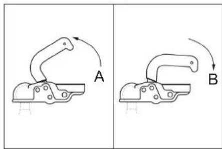
Aa>gs
Baalc
JcIaill.0sll JcJg 19 (29)
s|glo 20 (gl) Jawl jll aal
joll 100
<.0j
0000 0000
EC = OD = 25,PQ = PC = 4
olullalalglc/2
elll jolll elll jcl bdo
Joo
Jw.2
Lslo
#
J2alCjSginaa
Jlll baiial aiao 1000 ssi
pjjll iic cjjll oooe o
(a|a||g a||a||j# j#i)
J
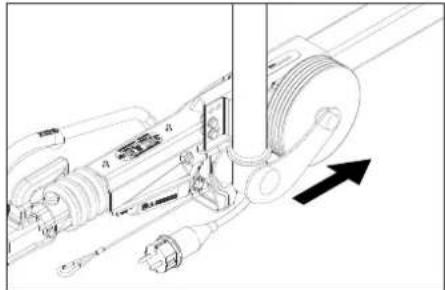
aai aai ai aai ai
gio 0jogal
←
.
Joljoljllb0
Jolal Jlaa 5aaag
j421 c, a oolg jzulao olu
aai 1g>g C0 00jblbU 200>
a. aaloo
←
aJalal JlaJIJIJIJIJI
0gjall jlll aal al gjol 0c1o:
Lg,pljUJgOjglana
aJJI JaiJI
Jusssll 1s
在 Rt ABD 中:
jglglogawzaiollbs
a/1g/a a/11 a/11 a/11 0c/10c
aolllll 1111111
0oJ 1/11 Jaiil aIac cJ
1/20120g 100g/11
gll aaaaall ggeell 0 U/1jge//g jgeU
b = 3
Jc Jn Jn Jn Jn Jn Jn Jn
a0j1/1p12
a/aa>1, Jw/aa>0
jaiil gai jaoxw s1gipc
.
a9j0g9j1/ jgl0jgl0j
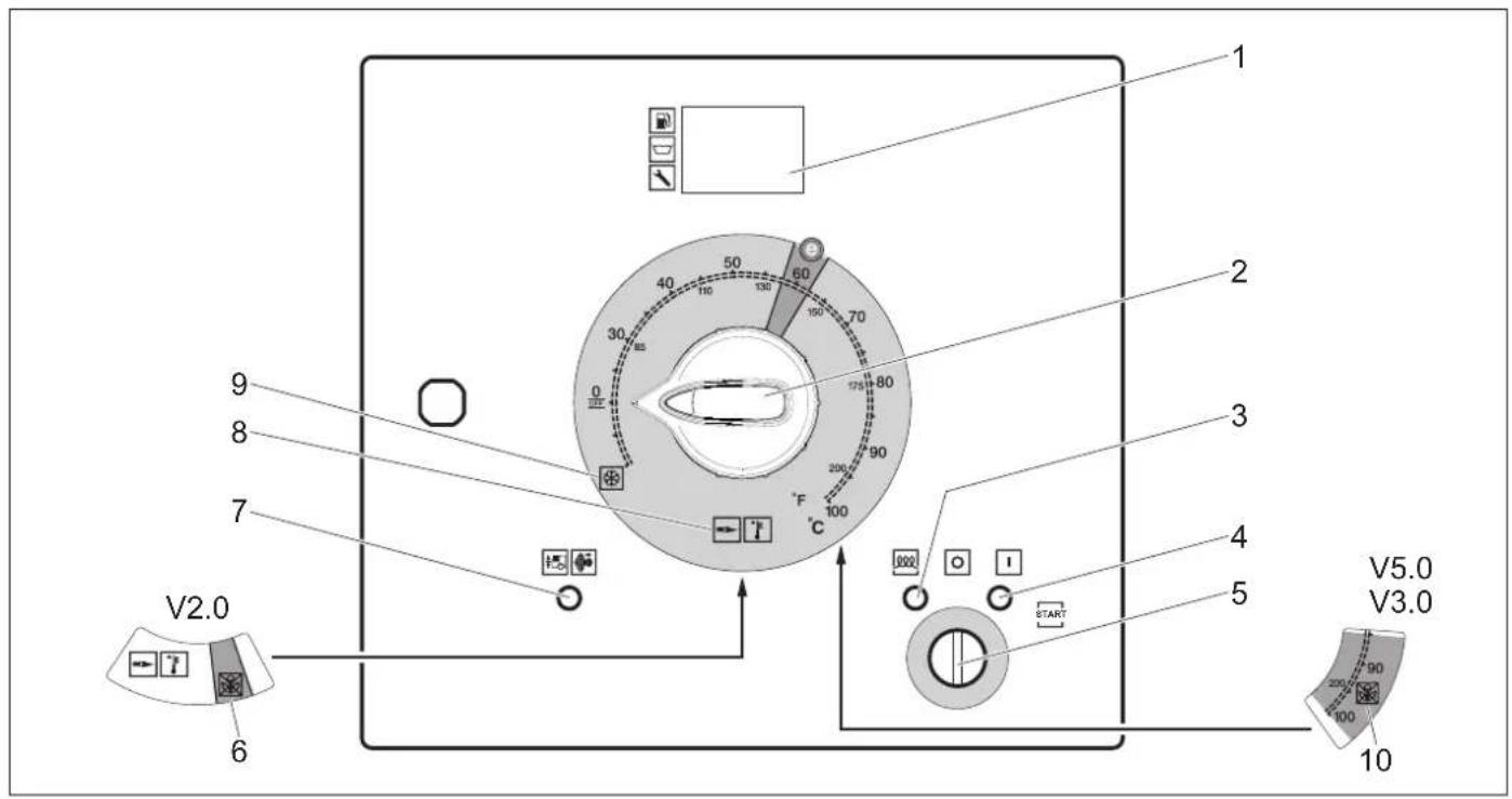
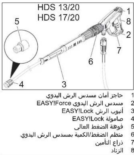
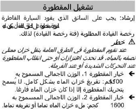
UlaUl 10gUwGswUul>Osc UuclB 151 11111111111111111111
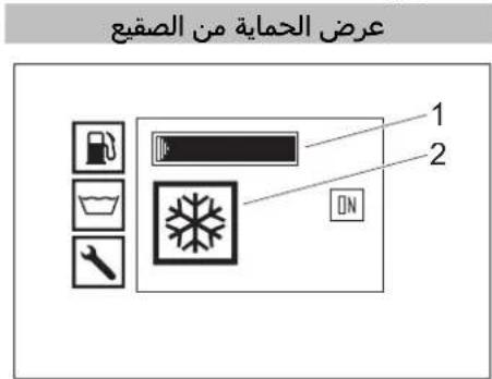
aloggagill gogg|gall aal 47
Jlll
gagll jolalac 48
s > | a| a > 0 49
Jellal laaill gpoj 24
sylgall 250
joo jjo jilw o27
gaiall o aIaI Ioslo 28
olaaagjgogggl jss 29
gall o aIa> s9s plao 30
olaluljssgws
aal 32
Jgllac,psill 33
34
JilwunjulJolc Jo a9 35
E>JU Jg>J gJgPlo 36
37
(li)a,béill 38
(1jw)abzill a2a0 39
40
41
2aill 42
sloogb> 43
44olal jds 21
joglo 45
wJU u 22
aloggagglgogglgalllll46
Jlllal baiil 23
1JjJ
2bωg
- Jll
4.
5
6Jx
7(1,Lw)el
8glll
9gai
0a
- 5,6 ,
2j
32g9g a
4c
5JLul
6(lai)cl
7
8
9
20
21
22
23
pIc
j_Lg 二山
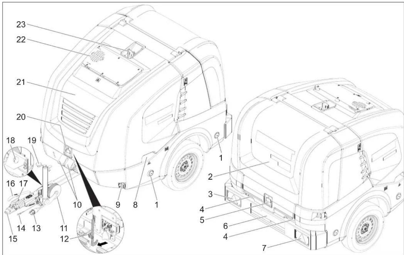
(1Jw)
1
2.
30
4.
5.
6
70
()
8
9.
105
1aa
2
30.
4山
Jw 15
Jol6 16
Jalllg 17
oJswll oelol Joggi adog Jol> 18
aill albc dS 19
Lulllalj 20
olol ciaac 21
22p5
gJ
| aolgell √jz √olall √a √jz √gi √a √jz √gi √a √jz √gi √a √jz √gi √a √jz √gi √a √jz √gi √a √jz √gi √a √jz √gi √a √jz √gi √a √jz √gi √a √jz √a √jz √gi √a √jz √gi √a √jz √gi √a √jz √gi √a √jz √gi √a √jz √gi √a √jz √gi √a √jz √gi √a √jz √gi √a √jz √ga √gi √a √jz √ga √a √jz √ga √a √jz √ga √a √jz √ga √a √jz √ga √a √jz √ga √a √jz √ga √a √jz √ga √a √jz √ga √a √jz √ga √a √jz √g |
| aai √i √j √k √l √m √n √o √p √q √r √s √t √u √v √w √x √y √z √aa √bb √c √d √e √f √g √h √i √j √k √l √m √n √n √o √p √q √r √s √t √u √v √m √n √n √o √p √q √r √s √t √u √v √w √x √y √z √c √d √e √f √g √h √i √j √k √l √m √n √n √o √p √q √r √s √t √u √v √m √n √n √o √p √q √r √s √t √u √v √w (∇a √b √c √d √e √f √g √h √i √j √k √l √m √n √n √o √p √q √r √s √t √u √v √m √n √n √o √p √q √r √s √t √u √v √w (∠a √b √c √d √e √f √g √h √i √j √k √l √m √n √n √o √p √q √r √s √t √u √v √w (∠a √b √c √d √e √f √g √h √i √j √k √l √m √n √n √o √p √q √r √s √t (∇a √b √c √d √e √f √g √h √i √j √k √l √m √n √n √o √p √q √r √s √t (∇a √b √c √d √e √f √g √h √i √j √k √l √n √n √o √p √q √r √s √t (∇a √b √c √d √e √f √g √h √i √j √k √l √n √n √o √p √q √r √s √t (∇a √b √c √d √e (∇a √b √c √d √e √f √g √h √i √j √k √l √n √n √o √p √q √r √s √t (∇a √b √c √d √e √f √g √h √i √j √k √l √n (∇a √b √c √d √e √f √g √h √i √j √k √l √n (∇a √b √c √d √e √f √g √h √i √j √k √l √n (∇a √b √c √d √e √f √g (∇a √b √c √d √e √f √g √h √i √j √k √l √n (∇a √b √c √d √e √f √g (∇a √b √c √d √e √f √g (∇a √b √c √d √e √f √g (∇a √b √c √d √e √f √g (∇a √b √c √d √e √f √g (∇a √b √c √d √e (∇a √b √c √d √e √f √g (∇a √b √c √d √e √f (∇a √b √c √d √e √f (∇a √b √c √d √e (∇a √b √c √d √e (∇a √b √c √d √e (∇a √b √c √d √e (∇a √b √c √d √e (∇a √b √c √d √e (∇a √b √c √d √e (∇a √b √c (∇a √b √c √d (∇a √b √c (∇a √b √c (∇a √b √c (∇a √b (∇a √b (∇a √b (∇a √b (∇a √b (∇a √b (∇a √b (∇a √b (∇a √b (∇a √b (∇a √b (∇a √b (∇a √b (∇a √b (∇a √b (∇a √b (∇a √b (∇a (∇a √b (∇a √b (∇a √b (∇a (∇a (∇a (∇a (∇a (∇a (∇a (∇a (∇a (∇a (∇a (∇a (∇a (∇a (∇a (∇a (∇a (∇a (∇a (∇a (∇a (∇a (∇a (∇a (∇a (∇a (∇a (∇a (∇a (∇a (∇a (∇a (∇a (∇a (\�a (∇a (∇a (∇a (∇a (∇a (∇a (∇a (∇a (∇a (∇a (∇a (∇a (∇a (∇a (∇a (∇a (∇a (∇a (∇a (∇a (∇a (∇a (∇a (∇a (∇a (∇a (∇a (∇a (∇a (∇a (∇a (∇a (∃∆ (∇a (∇a (∇a (∇a (∇a (∇a (∇a (∇a (∇a (∇a (∇a (∇a (∇a (∇a (∇a (∇a (∇a (∇a (∇a (∇a (∇a (∇a (∇a (∇a (∇a (∇a (∇a (∇a (∇a (∇a (∇a (∇a (∇a (∇∆ (∇a (∇a (∇a (∇a (∇a (∇a (∇a (∇a (∇a (∇a (∇a (∇a (∇a (∇a (∇a (∇a (∇a (∇a (∇a (∇a (∇a (∇a (∇a (∇a (∇a (∇a (∇a (∇a (∇a (∇a (∇a (∇a (∇α (∇a (∇a (∇a (∇a (∇a (∇a (∇a (∇a (∇a (∇a (∇a (∇a (∇a (∇a (∇a (∇a (∇a (∇a (∇a (∇a (∇a (∇a (∇a (∇a (∇a (∇a (∇a (∇a (∇a (∇a (∇a (∇a (∇a ((∇∆ (∇a (∇a (∇a (∇a (∇a (∇a (∇a (∇a (∇a (∇a (∇a (∇a (∇a (∇a (∇a (∇a (∇a (∇a (∇a (∇a (∇a (∇a (∇a (∇a (∇a (∇a (∇a (∇a (∇a (∇a (∇a (∇a (∕∆ (∇a (∇a (∇a (∇a (∇a (∇a (∇a (∇a (∇a (∇a (∇a (∇a (∇a (∇a (∇a (∇a (∇a (∇a (∇a (∇a (∇a (∇a (∇a (∇a (∇a (∇a (∇a (∇a (∇a (∇a (∇a (∇a (∇ a (∇a (∇a (∇a (∇a (∇a (∇a (∇a (∇a (∇a (∇a (∇a (∇a (∇a (∇a (∇a (∇a (∇a (∇a (∇a (∇a (∇a (∇a (∇a (∇a (∇a (∇a (∇a (∇a (∇a (∇a (∇a (∇a (∇a/(∇∆ (∇a (∇a (∇a (∇a (∇a (∇a (∇a (∇a (∇a (∇a (∇a (∇a (∇a (∇a (∇a (∇a (∇a (∇a (∇a (∇a (∇a (∇a (∇a (∇a (∇a (∇a (∇a (∇a (∇a (∇a (∇a (∇a (∃∆ (∇∆ (∇a (∇a (∇a (∇a (∇a (∇a (∇a (∇a (∇a (∇a (∇a (∇a (∇a (∇a (∇a (∇a (∇a (∇a (∇a (∇a (∇a (∇a (∇a (∇a (∇a (∇a (∇a (∇a (∇a (∇a (∇a (∇a (∇∆ (∇∆ (∇∆ (∇∆ (∇∆ (∇∆ (∇∆ (∇∆ (∇∆ (∇∆ (∇∆ (∇∆ (∇∆ (∇∆ (∇∆ (∇∆ (∇∆ (∇∆ (∇∆ (∇∆ (∇∆ (∇∆ (∇∆ (∇∆ (∇∆ (∇∆ (∇∆ (∇∆ (∇∆ (∇∆ (∇∆ (∇∆ (∇∆ (∇∆(∇∆ (∇∆ (∇∆ (∇∆ (∇∆ (∇∆ (∇∆ (∇∆ (∇∆ (∇∆ (∇∆ (∇∆ (∇∆ (∇∆ (∇∆ (∇∆ (∇∆ (∇∆ (∇∆ (∇∆ (∇∆ (∇∆ (∇∆ (∇∆ (∇∆ (∇∆ (∇∆ (∇∆ (∇∆ (∇∆ (∇∆ (∇∆ (∇∆ (η∆ (η∆ (η∆ (η∆ (η∆ (η∆ (η∆ (η∆ (η∆ (η∆ (η∆ (η∆ (η∆ (η∆ (η∆ (η∆ (η∆ (η∆ (η∆ (η∆ (η∆ (η∆ (η∆ (η∆ (η∆ (η∆ (η∆ (η∆ (η∆ (η∆ (η∆ (η∆ (η∆ (η△ (η∆ (η∆ (η∆ (η∆ (η∆ (η∆ (η∆ (η∆ (η∆ (η∆ (η∆ (η∆ (η∆ (η∆ (η∆ (η∆ (η∆ (η∆ (η∆ (η∆ (η∆ (η∆ (η∆ (η∆ (η∆ (η∆ (η∆ (η∆ (η∆ (η∆ (η∆ (η∆ (η∆(η∆ (η∆ (η∆ (η∆ (η∆ (η∆ (η∆ (η∆ (η∆ (η∆ (η∆ (η∆ (η∆ (η∆ (η∆ (η∆ (η∆ (η∆ (η∆ (η∆ (η∆ (η∆ (η∆ (η∆ (η∆ (η∆ (η∆ (η∆ (η∆ (η∆ (η∆ (η∆ (η∆ (eta (∞η (∞η (∞η (∞η (∞η (∞η (∞η (∞η (∞η (∞η (∞η (∞η (∞η (∞η (∞η (∞η (∞η (∞η (∞η (∞η (∞η (∞η (∞η (∞η (∞η (∞η (∞η (∞η (∞η (∞η (∞η (∞η (∞η (∞η (η∆ (η∆ (η∆ (η∆ (η∆ (η∆ (η∆ (η∆ (η∆ (η∆ (η∆ (η∆ (η∆ (η∆ (η∆ (η∆ (η∆ (η∆ (η∆ (η∆ (η∆ (η∆ (η∆ (η∆ (η∆ (η∆ (η∆ (η∆ (η∆ (η∆ (η∆ (η∆ (η∆ - - - - - - - - - - - - - - - - - - - - - - - - - - - - - - - - - - - - - - - - - - - - - - - - - - - - - - - - - - - - - - - - - - - - - - - - - - - - - - - - - - - - - - - - - - - - - - - - - - - - - - - - - - - - - - - - - - - - - - - - - - - - - - - - - - - - - - - - - - - - - - - - - - - - - - - - - - - - - - - - - - - - - - - - - - - - - - - - - - - - - - - - - - - - - - - - - - - - - - - - 0.99999999999999999999999999999999999999999999999999999999999999999999999999999999999999999999999999998888888888888888888888888888888888888888888888888888888888888888888888888888888888888888888888888888 |
aolal aai
gshd aie sho 15 Jsw oall sdoJg>Jb8 JaoI IERROR5:J2llaw
gill 21a/la/ll 21
glal ygdl jz/1211 4sJ U - .sw g gl oall jg dE jll ERROR5:Jlill
ggl gssuua j
jgl jgl JgJgJgJgJgJgJgJgJgJgJgJgJgJgJgJgJgJgJgJgJgJgJgJgJgJgJgJgJgJgJgJgJgJgJgJgJgJgJgJgJgJgJgJgJgJgJgJgJgJgJg
jzol all coj bao
11111111111111111111111111111111
0211 0j1 jzjjz
glal joljge aJg 2000 gag - aalaaeae oJg Jgogg lgl Jg jol. ERROR9:JlJIaJw
jolla aJlro aJr aJr
Jl jll jll oall oj Jg| 15
Aglk
111 1
g 12 gI ERROR 11:JLJIaW
iuiu u jglu 1uul uau
jgl jgl lglg jgl p13 0 g jgl gag a945al aiwai (gall) jglll 15gI ERROR 14:JlAL aw
JU
ggs ggl wssg>gall lcll jgj
a[bo]
LJd jn J
OjIgJgJgJgJgJgJgJgJgJgJgJgJgJgJgJgJgJgJgJgJgJgJgJgJgJgJgJgJgJgJgJgJgJgJgJgJgJgJgJgJgJgJgJgJgJgJgJgJgJgJg
JUUL
G 1111111111111111
isolgball 2140
2100JcIb01:0010g0g0s0g0g0g0g0g0g0g0g0g0g0g0g0g0g0g0g0g0g0g0g0g0g0g0g0g0g0g0g0g0g0g0g0g0g
olullclalol
olUclalUgSloUJglJ 1s
lae
Gsw,luuillcuUolUclaljgPbI
/olUclalUpszllcuaegjgl
JU UUULsJGLLZ
jailall plao
gws. gles jlll bsall wssn lks Jg
laiaai aiaa paaag yiljll plao gaiy
gio ay uai aolgl all jll oalll gjll
a gawaal laell bao jgai
:HDS 17/20 g HDS 13/20 J
/laiaial alti qbiu cjc glall aas jdi
qill plao zaiw, jlll baiall waaai
giolgal all jll slall no gjz
gajg sll plall gogoo) olall ulj
.(gjll
Jg no galegsbgaia jaliall plao
.eaell aojry sU U alao uug. gaiall
jollplao
Jgssll plao Jbae sic JlaUl plao 29 p - - - - - - - - - - - - - - - - - - - - - - - - - - - - - - - - - - - - - - - - -
aJbJI JjJzJw aJr
aJbI Jxw xie jLgJxwJzjT JgJI JgJW gJERROR1:JJIaJW
aill ool olall jdo ojra d aai 1
aull oall jdo aorjra gjg jzjg 1
jglal qw gsw qgwsall oarjrrg 1
qll al ool ojra gjg jzjg 1
jglal qw gsw qgwsall oarjrrg 1
ERROR3:jjllaw
aI
jlgjllc0g>gall jgsjll
bs A 1 jz/1 jz/1 aww U/1aaw/1 kss - aia/1 slo/1 J211299g/12i1w/g/4swg/2jx,aaU-
Sagalewglololalglawylll 1j
J, jU/0oJg// U
aolcblai
aiaai / aiai / olaie / oie / oio >1 -
aieal all aiaall claleill ocl 1001 -
o aIg/4 glee Ieauall 1022 11
jusll aai jwug pblil olal
jgl jge o jlc jzll jwul o jz
loog plbui adjla//o jg// 229
Emaill ldo /aiaa/daia// cladieil
eog / clo2lo agga,0jg/11 // 1c
li/llbaiallaabiljgejewy
aJg no oJgU aJgUJIaIJI JI
aW coJ.ayLlal alall cJglal Lda
oJgU jgeJauu Jauu U
gill lc Jaa211 dCay .dJgig
J59 sU 1111 aoeia11
Jluw all aebal all jz
jigll 116 jgeLL wolll
goglaiaaoa0jgallojg>111c
Sio jui jie211 a29 0g 000//uui uai/2i/ll iab jao a2w j9 00 59//a>gi//y ui piell ajiull
J1e>11 1c J1e>11
U
100 aJy oJaiieal lJyI JgJy 100aJyOJaiieal IJyI JgJy 100aJyOJaiieal IJyI JgJy 100aJyOJaiieal IJyI JgJy 100aJyOJaiieal IJyI JgJy 100aJyOJaiieal IJyI JgJy 100aJyOJaiieal
Jellalbaiaolgbsj
ai a ai 分母最小值为 k .
aolll lall baiall aibj s gawosuiu U o jzig lll laiaill gabj 10 uusu
aai//lll/ gagallb2al1
aogjgjy jlll b2ai/10gjx 229 -
dc gai jll pbljflp1zui/1c agil /
.
g// 0.01111111111111111111111111111111111111
aoljicU U 1/ll b22/10gj> 49
a1i/s1ai/sllgj,11/0laawlccagil H 4 jolb cal/1s/13/ aajg/0aaqgl
aai /iaeJ, /leI baeJI gabc J 1
0000000000000000000000000000000000000000000000000000000000000000
.
JyIyIyIyIyIyIyIyIyIyIyIyIyIyIyIyIyIyIyIyIyIyIyIyIyIyIyIyIyIy
laIwJbawU/wwuJbU
1
gauu/1 gaiu/1 1
aallll lallll
baa wla jgll:baa wll s s:laj (wll)
Jalilg29g 0c al> aolg jglll pdo
11111111111
dellg jlllgl aIjlllllal:
g 120g gall
ab 全
aiealollwllcldeoljpoillaolllb2 9g12ggl2gjlll0k20 jqz//p/2xwl all 5
Jgsss jll olol oog pge Jc g J
Jgall olal aag gl aaggl llaaee 0
UJl Jkglg Jdall Jc g Jy dJ
CjJolaoojo
olall aegollalio
Jl dU U JdUeJg 2
go Jolal p sJgU pluul Uj
JU JdU bUg UdU I dU clauu U g jgl
G>U p u u u u u u u u u u u u u u u u u u u u u u u u u u u u u u u u u u u u u u uu U
一
#
1 AR .
1 AR .
1 AR .
1 AR .
1 AR .
1 AR .
2 AR .
2 AR .
2 AR .
3 AR .
5 AR .
5 AR .
6 AR .
7 AR .
10 AR .
13 AR .
15 AR .
15 AR .
16 AR .
aiu|aL>
oal alg aol al gall oal clal pdo y plaluU Oo ool ool p j aai all aolll

alg aag algo aaall oge>U 0laaiuul seu piauiuug yogdull oLcU Cui jll uall Jgogaa gao .log iJ. aiil lglall no arw log gnoe aadoll oge>Ul no alol

JgUgU Jaa Ua Ua Ua Ua Ua Ua Ua Ua Ua Ua Ua Ua Ua Ua Ua Ua Ua Ua Ua Ua Ua Ua Ua Ua Ua Ua Ua Ua Ua Ua Ua Ua Ua Ua Ua Ua Ua Ua Ua Ua Ua Ua Ua Ua Ua Ua Ua Ua Ua Ua Uab 000000000000000000000000000000000000000000000000000000000000000000000000000000000000000
aill cjj jll cjj jgogjclll pse c 2
alil g aJU Ula> .aiill Jn jzjjg Jzjjg
aill a>ll no aill oog, pde ll g
(REACH) cJgSall J> dJdJI
olal, jyj 10000000000000000000000000000000000000000000000000000000000000000000000000000000
Jz
bsA
//a/ a/01/01/01/01/01/01/01/01/01/01/01/01/01/01/01/01/01/01/01/01/01/01/01/01/01/01/01/01/01/01/01/01/01/01

THANK YOU!
MERCI! DANKE! iGRACIAS!

Register your product and benefit from many advantages.
www.kaercher.com/welcome


Rate your product and tell us your opinion.
www.kaercher.com/dealersearch
Alfred Kärcher SE & Co. KG
Alfred-Karcher-Str. 28-40
71364 Winnenden (Germany)