
RBC31SBO - String trimmers RYOBI - Free user manual and instructions
Find the device manual for free RBC31SBO RYOBI in PDF.

| Product type | Petrol string trimmer / brushcutter |
| Brand | RYOBI |
| Model | RBC31SBO |
| Engine | 2-stroke, air-cooled |
| Displacement | 31 cm³ |
| Guaranteed sound power | 113 dB(A) |
| Fuel | Unleaded petrol (91+ octane) mixed with 2-stroke oil (50:1 ratio) |
| Main functions | Cutting tall grass, weeds, bushes (with Tri-Arc™ blade) |
| Included accessories | ReelEasy™ cutting head, Tri-Arc™ blade, blade guard, grass deflector, harness |
| Safety | Blade guard, debris shield, trigger lock, emergency stop, harness with quick release |
| Starting type | Manual (pull-start) or optional electric (OES18) |
| Routine maintenance | Clean air filter every 25h, check spark plug every 6 months, replace fuel filter annually |
| Warranty | 2 years (extendable with online registration) |
| Intended use | Outdoor, well-ventilated areas, adults only |
| Weight | Approximately 5 kg (estimate) |
| Material | Aluminium and reinforced plastic |
| Cutting line type | Nylon, diameter according to specifications (not specified) |
| Repairability | Original spare parts available, repair by authorized service center |
Frequently Asked Questions - RBC31SBO RYOBI
User questions about RBC31SBO RYOBI
0 question about this device. Answer the ones you know or ask your own.
Ask a new question about this device
Download the instructions for your String trimmers in PDF format for free! Find your manual RBC31SBO - RYOBI and take your electronic device back in hand. On this page are published all the documents necessary for the use of your device. RBC31SBO by RYOBI.
USER MANUAL RBC31SBO RYOBI
natural_image
Two identical MACHS tool holders with metal blades and adjustable arms, shown from different angles (no text or symbols visible)


| Important! | It is essential that you read the instructions in this manual before assembling, maintaining and operating the product. |
| Attention! | Il est essentiel que vous lisiez les instructions contenues dans ce manuel avant d'assembler, d'entretenir et d'utiliser le produit. |
| Achtung! | Es ist wichtig, dass Sie vor Zusammenbau, Wartung und Benutzung des Produktes die Anweisungen in dieser Anleitung lesen. |
| ¡Atención! | Resulta fundamental que lea este manual de instrucciones antes de realizar el montaje, el mantenimiento y de utilizar este producto |
| Attenzione! | E' importante leggere le istruzioni contenute nel presente manuale prima di montare il prodotto, svolgere le operazioni di manutenzione sullo stesso e metterlo in funzione. |
| Let op! | Het is van essentieel belang dat u de instructies in deze gebruiksaanwijzing leest voor u het product monteert, onderhoudt en gebruikt. |
| Atenção! | É fundamental que leia as instruções deste manual antes da montagem, manutenção e operação do aparelho. |
| OBS! | Det er vigtigt, at man læser instrukserne i denne brugsanvisning, inden man samler, vedligeholder og betjener produktet. |
| Observera! | Det är viktigt att du läser instruktionerna i manualen före montering, användning och underhåll av produkten. |
| Huomio! | On tärkeää, että luet tämän käsikirjan ohjeet ennen tuotteen kokoamista, huoltoa ja käyttöä. |
| Advarsel! | Det er viktig at du leser instruksjonene i denne manualen før sammensetning, vedlikehold og bruk av produktet |
| Внимание! | Необходимо прочитать инструкции в данном руководстве перед сборкой, обслуживанием и эксплуатацией этого изделия. |
| Uwaga! | Koniecznie należy przeczytać instrukcje zawarte w tym podręczniku przed montażem, obsługą oraz konserwacją produktu. |
| Dûležité upozornění! | Neinstalujte, neprovádějte údržbu ani nepoužívejte tento výrobek dříve, než si přečtete pokyny uvedené v tomto návodu. |
| Figyelem! | Fontos, hogy a termék összeszerelése, karbantartása és használata előtt elolvassa a kézikönyvben található utasításokat. |
| Atenție! | Este esențial să citiți instrucțiunile din acest manual înainte de asamblare, efectuarea întreținerii și operarea produsului. |
| Uzmanību! | Ir svarīgi izlasīt šīs rokasgrāmatas instrukcijas pirms uzstādīšanas, apkopes un preces darbināšanas. |
| Dèmesio! | Prieš surenkant, prižiūrint ir naudojant gaminį, būtina perskaityti šiame vadove pateiktus nurodymus. |
| Tähtis! | Enne masina kokkupanekut, hooldamist ja kasutama hakkamist tuleb käesolevas juhendis esitatud juhised kindlasti läbi lugeda. |
| Upozorenje! | Vrlo je važno da ste prije sklapanja, održavanja i rada s ovim proizvodom pročitali upute u ovom priručniku. |
| Pomembno! | Pomembno je da pred montažo vzdrževanjem in uporabo tega izdelka preberete navodila v tem priročniku. |
| Upzornenie! | Je dôležité, aby ste si pred montážou, údržbou a obsluhou produktu prečitali pokyny v tomto návode. |
| Важно! | Изключително важно е да прочетете инструкциите в настоящото ръководство, преди да преминете към сглобяване, поддръжка или работа с продукта. |
| Важливо! | Дуже важливо, щоб ви прочитали інструкції в цьому керівництві перед складанням, обслуговуванням та експлуатацією цієї машини. |
| Önemli! | Ürünü monte etmeden, kullanmadan ve bakımını yapmadan önce bu kılavuzdaki talimatları okumanız önemlidir. |
Subject to technical modification | Sous réserve de modifications techniques | Technische Änderungen vorbehalten | Bajo reserva de modificaciones técnicas | Con riserva di eventuali modifiche tecniche | Technische wijzigingen voorbehouden | Com reserva de modificações técnicas | Med forbehold for tekniske ændringer | Med förbehåll för tekniska ändringar | Tekniset muutokset varataan | Med forbehold om tekniske endringer | могут быть внесены технические изменения | Z zastrzeżeniem modyfikacji technicznych | Změny technických údajů vyhrazeny | A můszaki módosítás jogát fenntartjuk | Sub rezerva modificațiilor tehnice | Paturam tiesības mainīt tehniskos raksturlielumus | Pasiliekant teisę daryti techninius pakeitimus | Tehnilised muudatused võimalikud | Podloæno tehniëkim promjenama | Tehnične spremembe dopuščene | Právo na technické zmeny je vyhradenė | Подлежи на технически модификации | Є ob’єктом для технічних змін | Teknik değişikliğe tabidir.


Safety, performance, and dependability have been given top priority in the design of your brushcutter/grass trimmer.
INTENDED USE
The brushcutter/grass trimmer is intended to be used only by adults who have read and understood the instructions and warnings in this manual and can be considered responsible for their actions. The product is only intended for use outdoors in a well ventilated area. For safety reasons, the product must be adequately controlled by using two-handed operation.
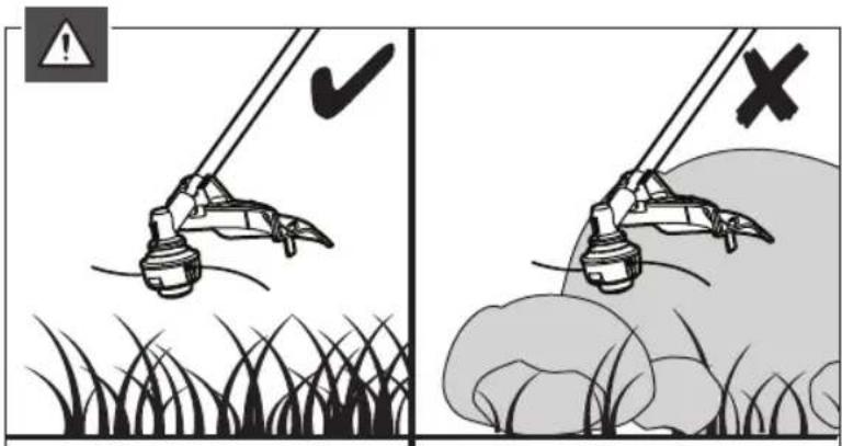
The product fi tted with the grass trimmer head (and appropriate guard) is intended for cutting long grass, pulpy weed, and similar vegetation at or about ground level. When fi tted with the Tri-Arc™ blade (and appropriate guard), it can also cut bushes. The product is not designed to be fi tted with a saw blade.
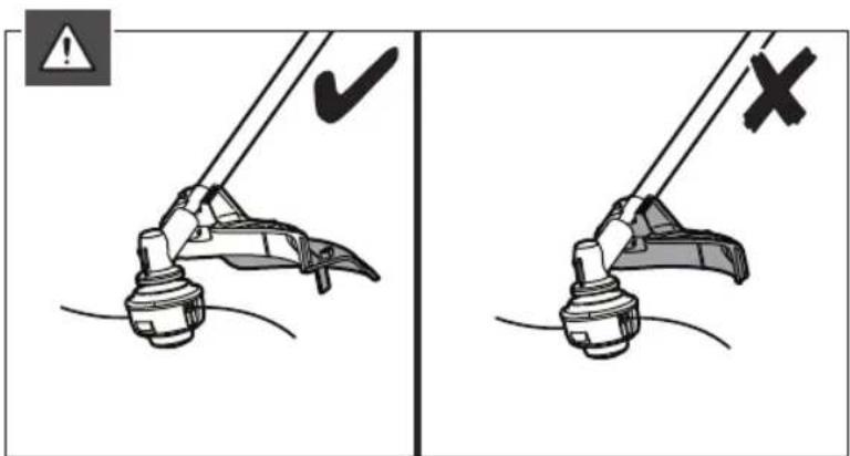
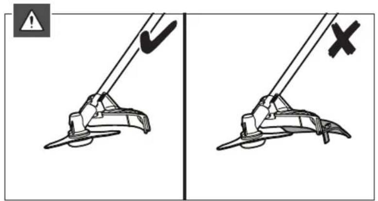
The cutting plane should be approximately parallel to the ground surface. The product should not be used to cut or trim hedges, bushes, or other vegetation where the cutting plane is not parallel to the ground surface.
Do not use the product for any other purpose.
WARNING
To reduce the risk of injury, the user must read and understand the operator's manual.
WARNING
Do not attempt to operate the product until you have read thoroughly and understood completely all instructions and safety rules contained in this manual. Failure to comply may result in accidents involving fire, electric shock, or serious personal injury. Save the operator's manual and review frequently for continuing safe operation, and instructing others who may use the product.
WARNING
The product is not intended to be used by children or persons with reduced physical, mental, or sensory capabilities. Children should be adequately supervised to ensure they do not play with the product.
GENERAL SAFETY WARNINGS
For safe operation, read and understand all instructions before using the product. Follow all safety instructions. Failure to follow all safety instructions listed below, can result in serious personal injury.
■ Some regions have regulations that restrict the use of the product. Check with your local authority for advice.
- Do not allow children or untrained individuals to use the product.
■ Never start or run the engine in a closed or poorly ventilated area; breathing exhaust fumes can kill.
- Clear the work area before each use. Remove all objects such as rocks, broken glass, nails, wire, or string, which can be thrown or become entangled in the
string head or blade.
■ Wear full eye and hearing protection while using the product. If working in an area where there is a risk of falling objects, head protection must be worn.
■ Hearing protection may restrict the operator's ability to hear warning sounds. Pay particular attention to potential hazards around and inside the working area.
■ Wear heavy long trousers, non-slip protective footwear and gloves. Do not wear loose fitting clothing, short trousers, jewellery of any kind, or use with bare feet.
- Secure long hair so it is above shoulder level to prevent entanglement in any moving parts.
- Keep all bystanders, children, and pets at least 15 m away. Stop the product if anyone enters the area.
■ Do not use the product when you are tired, ill, or under the influence of alcohol, drugs, or medication.
- Do not use in poor lighting. The operator needs clear unrestricted vision to identify potential hazards.
- Keep firm footing and balance at all times. Do not overreach. Overreaching can result in loss of balance or exposure to hot surfaces.
- Keep all parts of your body away from any moving part.
- Do not touch area around the silencer or cylinder of the product, these parts get hot from operation.
■ Always stop the engine and allow it to cool down before making any adjustments.
■ Do not smoke when mixing fuel or filling fuel tank.
■ Mix and store fuel in a container approved for fuel.
- Mix fuel outdoors where there are no sparks or flames. Wipe up any fuel spillage. Move 9 m away from refueling site before starting engine.
■ Stop the engine and allow to cool down before refueling or storing the product.
- Allow the engine to cool down; empty the fuel tank and secure the product from moving before transporting in a vehicle.
■ Always stop the engine and make sure all moving parts have come to stop before:
- servicing
• leaving the product unattended
• cleaning your product
- changing accessories
- clearing blockages
- checking for any damage after hitting an object
- checking for any damage if the product starts to vibrate abnormally
• performing maintenance
- removing blade
- installing blade
WARNING
Never use cutting means or attachments, which are not specified by Ryobi in this manual. This includes the use of metal multi-piece pivoting chains and flail-blades. These items are known to break up during use and present a high risk of serious injury to the operator or bystanders.
WARNING
Inspection after dropping or other impacts: Thoroughly inspect the product and identify any problems or damage to it. Any part that is damaged should be properly repaired or replaced by an authorised service centre.
GRASS TRIMMER SAFETY WARNINGS
- Replace the string head if cracked, chipped, or damaged in any way. Be sure the string head is properly installed and securely fastened. Failure to do so can cause serious injury.
■ Avoid using on wet grass.
■ Do not walk backwards when using the product.
■ Walk, never run.
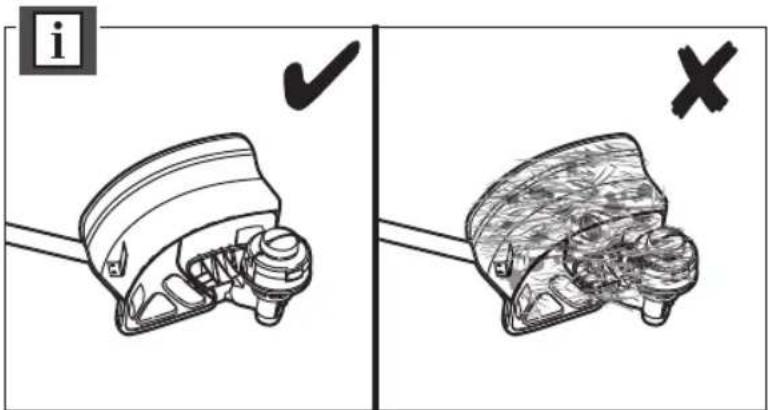
■ The small blade fitted to the cutting attachment guard is designed to trim the new extended line to the correct length for safe and optimum performance. It is very sharp; do not touch it, particularly when cleaning the product.
■ Always ensure that ventilation openings are kept clear of debris.
■ Before use and after any impact, check that there are no damaged parts. Examine the cutting means for signs of cracking or other damage. A defective switch or any part that is damaged should be properly repaired or replaced by an authorised service facility.
■ Make sure the head attachment is properly installed and securely fastened.
■ Make sure all guards, deflectors, handles, bolts, and fasteners are properly and securely attached.
■ Do not modify the product in any way. This may increase the risk of injury to yourself or others. - Use only the manufacturer's replacement line in the cutting head. Do not use any other cutting attachment.
■ Never use the product without the cutting attachment guard in place and in good condition. - Maintain a firm grip on both handles while trimming. Keep string head below waist level. Never cut with the string head located over 76 cm or more above the ground.
BRUSHCUTTER SAFETY WARNINGS
In addition to the above rules, these additional instructions are appropriate when using the product in brushcutter mode.
■ Use heavy-duty gloves while installing or removing the blades, they have sharp edges.
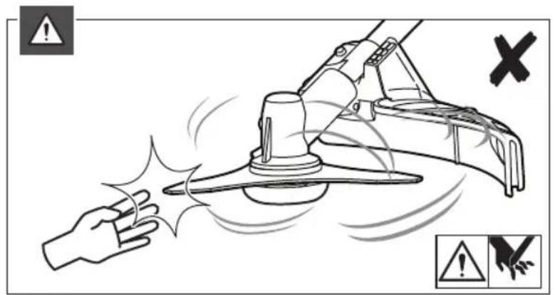
■ Do not attempt to touch or stop the blade when it is rotating.
■ A moving blade can cause severe injury. Maintain proper control of the product with both hands until the blade has completely stopped rotating.
- Replace any blade that has been damaged. Always make sure the blade is installed correctly and securely fastened before each use.
■ Use only the manufacturer's replacement Tri-Arc™ blade. Do not use any other cutting attachment.
■ Never cut any material over 13 mm diameter.
- Your brushcutter is fitted with a harness. Carefully adjust the harness to fit comfortably and help to support the weight of the product at your right side.
■ Identify the quick release mechanism and practice using it before you start using the product. Its correct use may prevent serious injury in case of an emergency. Never wear additional clothing over the harness or otherwise restrict access to the quick release mechanism.
■ Cover the blade with the blade protector before storing the product, or during transportation. Always remove the blade protector before using the product. If not removed, the blade protector could become a thrown object as the blade begins to turn.
Exercise extreme caution when using the blade with the product. Blade thrust is the reaction that may occur when the spinning blade contacts anything it cannot cut. This contact may cause the blade to stop for an instant, and suddenly "thrust" the product away from the object that was hit. This reaction can be violent enough to cause the operator to lose control of the product. Blade thrust may occur without warning if the blade snags, stalls, or binds. This is more likely to occur in areas where it is difficult to see the material being cut.
For cutting ease and safety, approach the weeds being cut from the right to the left. In the event an unexpected object or woody stock is encountered, this practice could minimise the blade thrust reaction. Both hands must be used at all times to control the product.
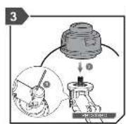
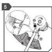
ASSEMBLY
UNPACKING
See page 181-182.
The product requires assembly.
■ Carefully remove the tool and any accessories from the box. Make sure that all items listed are included.
■ Inspect the tool carefully to make sure no breakage or damage occurred during shipping.
WARNING
If any parts are damaged or missing, do not operate the product until the parts are replaced. Failure to heed this warning could result in serious personal injury.
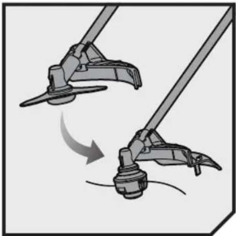
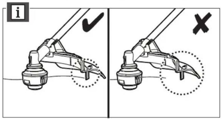
ADJUSTING THE STRAP HANGER
See page 185/189.
Adjust the strap hanger to a comfortable and balanced position where the blade or cutter attachment will suspend between 100 mm and 300 mm above the ground surface.
USING THE HARNESS
See page 185/189.
NOTE: Always use the harness with the product.
NOTE: To quickly release the product from the harness, sharply pull the quick-release tab.
2 | English
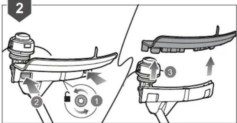
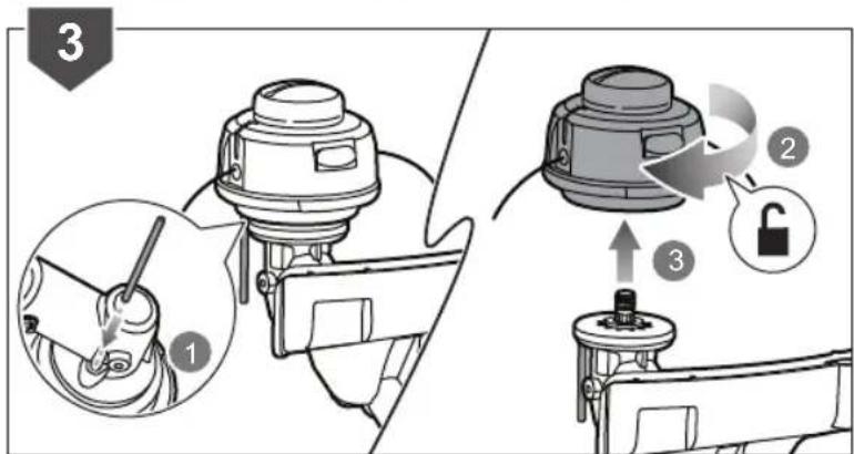
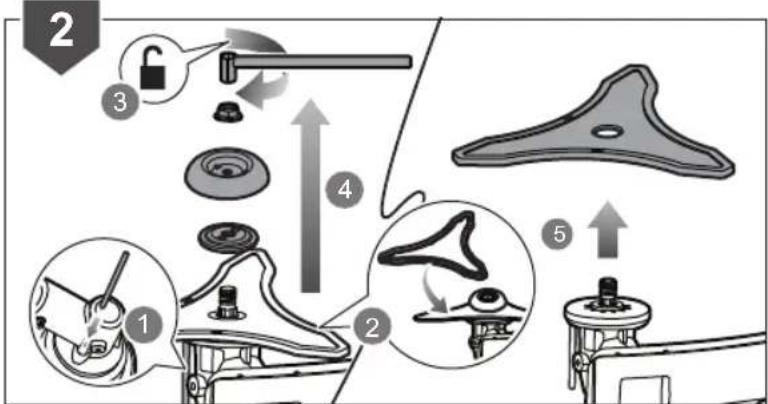
USING THE REELEASY™ GRASS TRIMMER HEAD AND TRI-ARC™ BLADE
- When using the ReelEasy™ grass trimmer head, the grass deflector must be attached to the blade guard. (See page 203).
■ When using the Tri-Arc™ blade, the grass deflector must be removed from the blade guard (See page 202).
WARNING
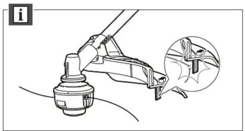
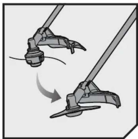
Always remove the pin for locking the gear shaft before starting the engine (see page 185, step 4).
OPERATION
FUELING AND REFUELING
See page 184.
■ Always handle fuel with care, it is highly flammable.
■ The product is powered by a 2-stroke engine and requires pre-mixing petrol and 2-stroke lubricant. Premix unleaded petrol and 2-stroke engine lubricant in a clean container approved for petrol.
This engine is certified to operate on unleaded petrol intended for automotive use with an octane rating of 91 ([R + M] / 2) or higher.
■ Do not use any type of pre-mixed petrol / lubricant from fuel service stations.
■ Use synthetic 2-stroke lubricant only. Do not use automotive lubricant or 2-stroke outboard lubricant.
■ Mix 2% synthetic 2-stroke lubricant into the petrol. This is a 50:1 ratio.
■ Mix the fuel thoroughly and also each time before fueling.
■ Mix in small quantities. Do not mix quantities larger than usable in a 30 day period. A synthetic 2-stroke lubricant containing a fuel stabilizer is recommended.
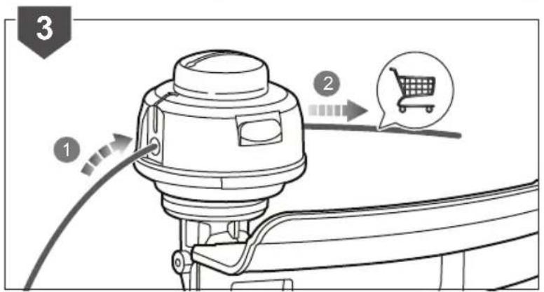
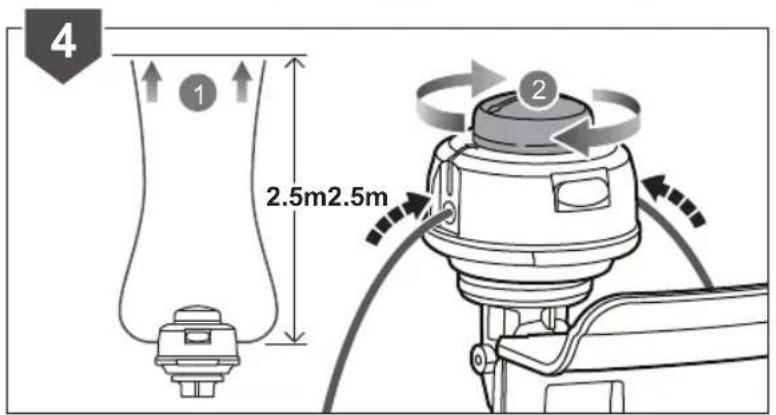
FILLING THE TANK
■ Clean surface around fuel cap to prevent contamination.
■ Loosen fuel cap slowly to release pressure and to keep fuel from escaping around the cap.
■ Carefully pour fuel mixture into the tank. Avoid spillage.
■ Prior to replacing the fuel cap, clean and inspect the gasket.
- Immediately replace fuel cap and hand tighten. Wipe upany fuel spillage. Move 9 m away from refueling site before starting engine.
STARTING THE ENGINE USING AN ELECTRICAL STARTER (OPTIONAL):
See page 196 to 201.
WARNING
Only use the Ryobi OES18 electrical starter. Use of any other starter may damage the engine and cause serious personal injury.
WARNING
Before using the electrical starter to start the product, please read and understand completely the operation manual of the OES18 electrical starter to avoid improper operation and serious personal injury.
- Hold the insulated shaft with your left hand and use your right hand to put the starter bit shaft to the shaft hole on the engine, otherwise the engine will not turn.
■ Make sure the starter bit is properly engaged.
NOTE: The electrical starter is equipped with a safety interlock. Do not press and hold on the switch button when putting the electrical starter shaft into the shaft hole on the engine. Also, the starter will not turn if the electrical starter is not properly engaged.
RBC31SESO: Hold the product with the right hand on the rear handle and the left hand on the front handle.
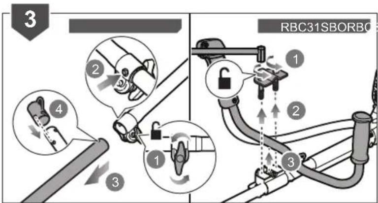
RBC31SBO: Hold the product with the right hand on the trigger handle and the left hand on the left handle.
- Keep a firm grip with both hands while in operation.
■ The product should be held at a comfortable position with the trigger handle about hip height.
■ Always operate the product at full throttle. Prolonged cutting at partial throttle will result in lubricant dripping from the silencer. - Cut tall grass from the top down to prevent grass from wrapping around the shaft housing and string head, which may cause damage from overheating.
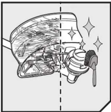
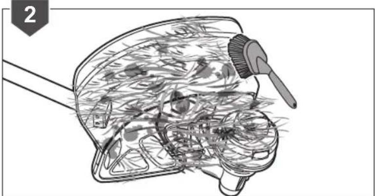
If grass or debris becomes wrapped around the cutting means, stop the engine. Wear heavy-duty gloves to prevent injury from the sharp blades and carefully remove the debris.
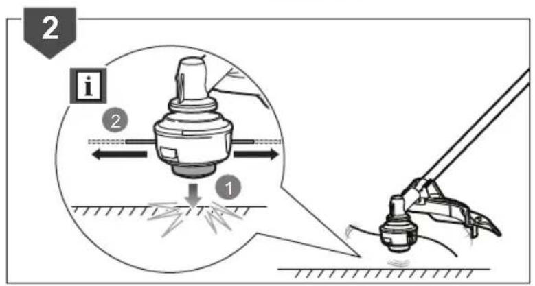
■ Do not push into the grass to be cut. Move from side to side. Move forward a little at the end of each sweep. - Keep the product tilted towards the area being cut.
■ Do not use in dangerous environments.
■ Use the tip of the string to do the cutting; do not force the string head into the uncut grass.
■ Wire and picket fences cause extra string wear, even breakage. Stone and brick walls, kerbs and wood may wear string rapidly. - Avoid trees and shrubs. Tree bark, wood mouldings, cladding and fence posts can be easily damaged by the string.
To help reduce the risk of kickback: Do not push into the material to be cut. Move from right to left in steady sweeps. Move forward a little at the beginning of each new sweep.
RBC31SESO: Hold the product with the right hand on the rear handle and the left hand on the front handle.
RBC31SBO: Hold the product with the right hand on the trigger handle and the left hand on the left handle.
■ The product should be held at a comfortable position with the trigger handle about hip height.
- Maintain your grip and balance on both feet. Position yourself so that you will not be drawn off balance by the kickback reaction of the cutting blade.
■ Adjust the strap hanger to a comfortable position.
Exercise extreme caution when using the blade with the product. Blade thrust is the reaction that may occur when the spinning blade contacts anything it cannot cut. This contact may cause the blade to stop for an instant, and suddenly "thrust" the product away from the object that was hit. This reaction can be violent enough to cause the operator to lose control of the product. Blade thrust may occur without warning if the blade snags, stalls, or binds. This is more likely to occur in areas where it is difficult to see the material being cut. For cutting ease and safety, approach the weeds being cut from the right to the left. In the event an unexpected object or woody stock is encountered, this could minimize the blade thrust reaction.
TRANSPORTATION AND STORAGE
■ Stop the engine and allow it to cool down before storing or transporting.
■ Clean all foreign materials from the product.
■ If a cutting blade is fitted, cover it with the blade protector.
- Drain all fuel from tank into a container approved for petrol. Remember to properly replace and tighten the fuel cap.
- Run the engine until it stops, this will remove all fuel that could become stale and leave varnish and gum in the fuel system.
■ Store the product in a cool, dry, and well-ventilated place that is inaccessible to children. Keep away from corrosive agents, such as garden chemicals and deicing salts. Do not store outdoors.
- When transporting the product in a vehicle, secure it against movement or falling to prevent injury to persons or damage to the product.
■ Never carry or transport the product while the engine is running.
- Abide all government and local regulations for the safety storage and handling of petrol. Excess fuel should be used in other 2-cycle engine powered equipment.
SHORT TERM
■ Stop the engine, and allow it to cool down before storing.
■ Clean all foreign material from the product.
■ Store the product in a cool, dry, and well-ventilated place that is inaccessible to children.
- Keep away from corrosive agents such as garden chemicals and de-icing salts.
■ Do not store outdoors.
MAINTENANCE
WARNING
Use only original manufacturer's replacement parts, accessories, and attachments. Failure to do so can cause possible injury, poor performance, and may void your warranty.
WARNING
The cutting attachment must not rotate in idle mode. If this requirement is not satisfied, the clutch has to be adjusted or the product needs an urgent maintenance by a qualified technician.
WARNING
A leaking fuel cap is a fire hazard and must be replaced immediately.
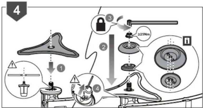
WARNING
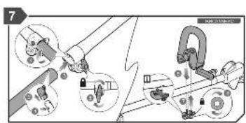
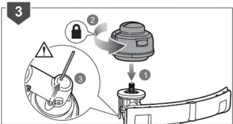
Note that the blade nut is a nylon nut, which is to be used for one time assembly only. Do not reuse the nylon nut. When installing/reinstalling, use a new nylon nut. Failure to follow this procedure can result in serious injury.
WARNING
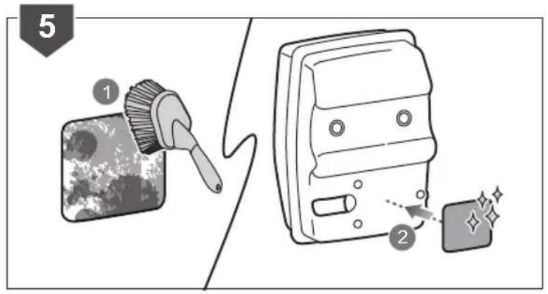
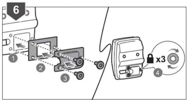
Make sure that the nut torque is ≥ 25Nm when assembling the blade. Failure to follow this procedure can result in serious injury. (See page 202, step 4)
■ Always stop the engine and allow it to cool down before making any maintenance.
■ You may make adjustments and repairs described in this manual. For other repairs, have the product serviced by an authorised service centre.
■ Consequences of improper maintenance may include excess carbon deposits resulting in loss of performance and discharge of black lubricant residue dripping from the muffler.
■ For replacement line, use only nylon filament line of the diameter described in the specification table of this manual.
■ After extending the new cutter line, always return the product to its normal operation position before starting. After each use, clean the product with a soft dry cloth.
■ Make sure all guards, straps, deflectors and handles are properly and securely attached to avoid the risk of personal injury.
1 These items should only be carried out by an authorised service centre.
2 If this requirement is not met, contact an authorised service centre for repair or adjustment.
MAINTENANCE SCHEDULE
| Check if fastener is fully tightened | Before each use |
| Check: Cutting attachment must not rotate in idle mode2 | Before each use |
| Check fuel hose Before each use | |
| Check all hose connections Before each use | |
| Clean fuel tank and fi lter1 | Every 3 months or 50 hours of operation |
| Replace fuel fi lter1 | Every year or after 300 hours or operation |
| Check fuel cap or fuel tank vapor vent (if equipped) for leakage | Before each use |
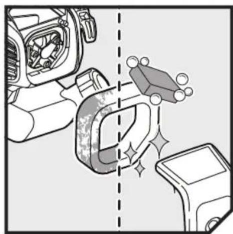
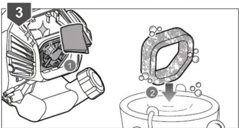
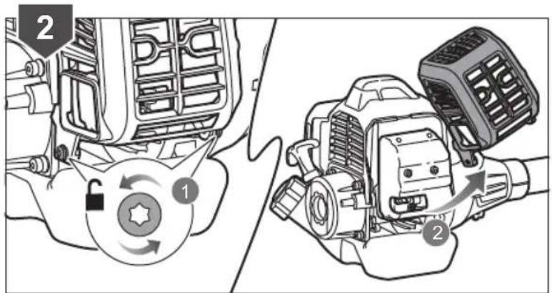
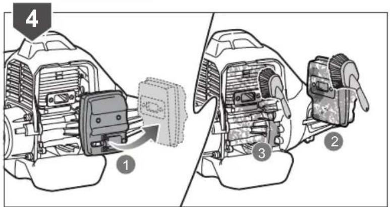
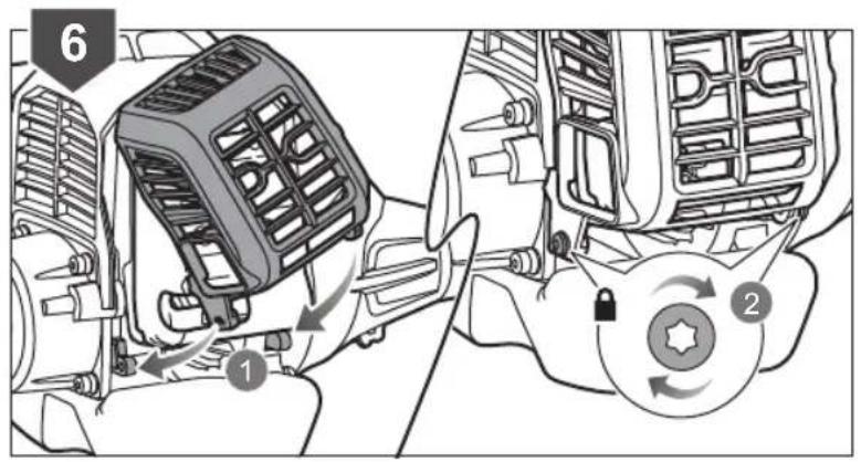
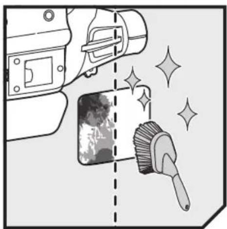
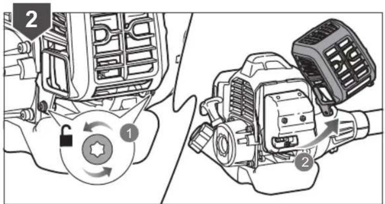
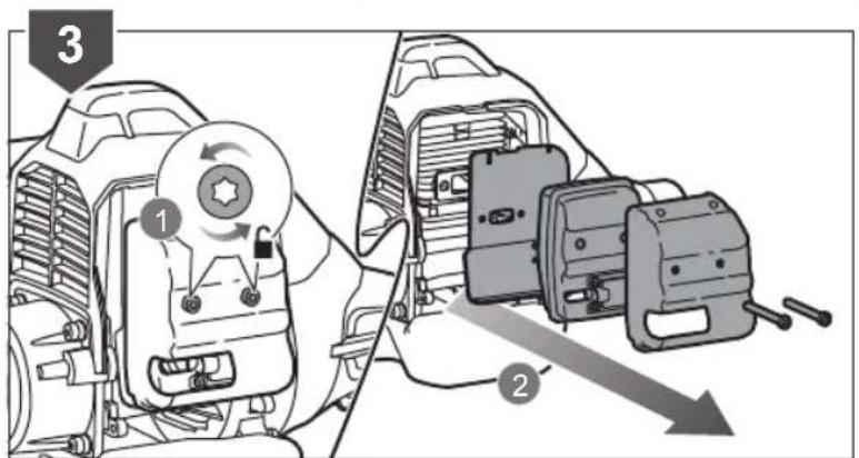
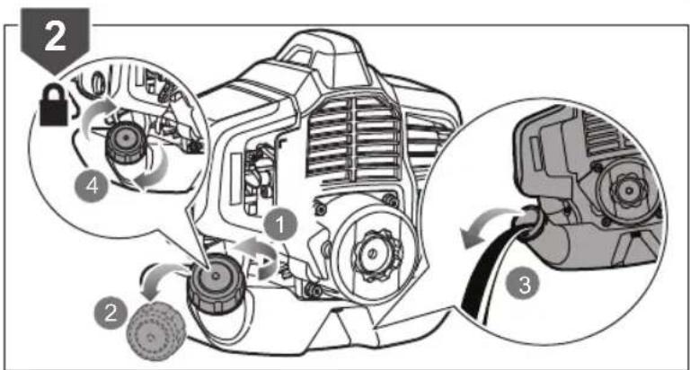
| Clean air fi lter Every 25 hours | |
| Change air fi lter Every year or | after 300 hours or operation |
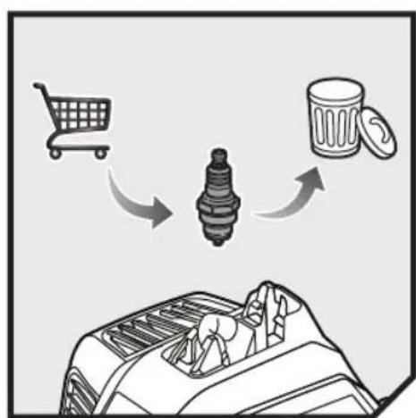
| Clean or adjust spark plug Every 6 months or 100 hours of operation | |
| Replace spark plug Every year or after 300 hours or operation | |
| Clean spark arrestor Every 25 hours | |
| Replace spark arrestor Every year or after 300 hours or operation | |
| Clean the exhaust port and silencer | Every 25 hours |
RESIDUAL RISKS
Even when the product is used as prescribed, it is still impossible to completely eliminate certain residual risk factors. The following hazards may arise in use and the operator should pay special attention to avoid the following:
■ Contact with cutting means
- Ensure that the blade protectors are fitted when the product is not in use. Keep hands and feet away from the blades at all times.
■ Injury caused by vibration
- Always use the right tool for the job, use designated handles, and restrict working time and exposure.
■ Hearing injury caused by exposure to noise
– Wear hearing protection and limit exposure.
■ Eye injury caused by flying debris
- Wear eye protection at all times.
■ Risk of falling objects
- Wear head protection if there is any risk of falling objects.
Kickback can occur when using the brushcutter. Ensure proper control by using both hands on the designated handles. Read and follow the directions elsewhere in this manual to help reduce the risk of kickback.
RISK REDUCTION
It has been reported that vibrations from handheld tools may contribute to a condition called Raynaud's Syndrome. Symptoms may include tingling, numbness and blanching of the fingers, usually apparent upon exposure to cold.
Hereditary factors, exposure to cold and dampness, diet, smoking and work practices are all thought to contribute to the development of these symptoms. There are measures that can be taken by the operator to possibly reduce the effects of vibration:
- Keep your body warm in cold weather. When operating the product, wear gloves to keep the hands and wrists warm. It is reported that cold weather is a major factor contributing to Reynaud's Syndrome.
■ After each period of operation, exercise to increase blood circulation.
■ Ensure that the product is correctly located in a designated working position before operating the product.
■ Limit the amount of exposure per day. Take frequent work breaks.
If you experience any of the symptoms of this condition, immediately discontinue use and see your physician.
WARNING
Injuries may be caused, or aggravated, by prolonged use of a tool. When using any tool for prolonged periods, ensure you take regular breaks.
KNOW YOUR PRODUCT
- Starter grip
- Fuel cap
- Bike handle (RBC31SBO)
- Drive shaft (RBC31SBO)
- Blade guard
- Grass deflector
- Nylon nut
- Blade washer
- Cupped washer
- Blade protector
- Tri-Arc™ blade
- Upper string head housing
- Spool
- Bump knob
- Lower string head housing
- Cutting line
- Throttle interlock (RBC31SBO)
- Throttle trigger (RBC31SBO)
- Ignition switch
- Throttle lock (RBC31SBO)
- Strap hanger
- Lower shaft (RBC31SESO)
- Knob (RBC31SESO)
- Upper shaft (RBC31SESO)
- Front handle (RBC31SESO)
- Throttle trigger (RBC31SESO)
- Throttle lock (RBC31SESO)
SYMBOLS ON THE PRODUCT

Safety alert

Read and understand all instructions before operating the product, follow all warnings and safety instructions.

Wear eye, ear, and head protection.

Wear non-slip safety footwear when using the product.

Wear non-slip, heavy-duty gloves.

Beware of thrown or flying objects. Keep all bystanders, especially children and pets, at least 15 m away from the operating area.

This product is not intended for use with a toothed saw type blade.

To reduce the risk of injury or damage, avoid contact with any hot surface.

Keep hands away from blades

Guaranteed sound power level

Run position

Set the choke lever to "Full" position.

Set the choke lever to "Half" position.

Waiting time: 10 seconds

PRIME - press the primer bulb 10 times slowly.

Pull the starter rope

Squeeze throttle trigger to start / run.

Lock the throttle in position by depressing the throttle interlock button.

Use unleaded petrol intended for motor vehicle use with an octane rating of 91([R+M]/2) or higher.

Use 2-stroke lubricant for air cooled engines.

Mix the fuel mix thoroughly and also each time before refueling.

Starting a cold engine by hand

Starting a warm engine by hand

Starting a cold engine by electrical starter

Starting a warm engine by electrical starter

Straight shaft symbol: When fitting the line spool to the cutting means, this symbol should be visible to the operator.

Tri-Arc™ blade is appropriate for the product and is suited for cutting pulpy weeds and vines.

Beware of blade thrust

Rotational direction and maximum speed of the shaft for the cutting attachment.

Pull: Quick release tab

Conforms to all regulatory standards in the country in the EU where the product is purchased.

EurAsian Conformity Mark

Ukrainian mark of conformity
The following signal words and meanings are intended to explain the levels of risk associated with this product.
DANGER
Indicates an imminently hazardous situation, which, if not avoided, will result in death or serious injury.
WARNING
Indicates a potentially hazardous situation, which, if not avoided, could result in death or serious injury.
CAUTION
Indicates a potentially hazardous situation, which, if not avoided, may result in minor or moderate injury.
CAUTION
Without safety alert symbol
Indicates a situation that may result in property damage.
SYMBOLS IN THIS MANUAL

Note

Warning


SYMBOLES APPLIQUÉS SUR LE PRODUIT

Avertissement

MACHEN SIE SICH MIT IHREM PRODUKT VERTRAUT
SYMBOLE AUF DEM PRODUKT

Sicherheitswarnung

COMBUSTIBLE Y REPOSTAJE
ALGEMENE VEILIGHEIDSWAARSCHUWINGEN
VEILIGHEIDSWAARSCHUWINGEN VOOR DE
BRÆNDSTOF OG OPTANKNING
Se side 184.
SYMBOLER PÅ PRODUKTET

Sikkerheds Varsel

TRANSPORT OCH FÖRVARING
FÖRVARING PÅ KORT SIKT
SYMBOLER PÅ PRODUKTEN

Säkerhetsvarning

KJENN PRODUKTET DITT
- Starthåndtak
- Lokk til drivstofftank
- RBC31SBO: Sykkelhåndtak
- RBC31SBO: Drivaksel
- Bladhylse
- Gressutkaster
- Nylonmutter
- Bladskive
- Buet skive
- Knivbeskytter
- Tri-Arc-kniv
- ∅vre strenghodehus
- Spole
- Støtknast
- Nedre strenghodehus
- Klippesnor
- RBC31SBO: Gass-sperre
- RBC31SBO: Gasshendel
-
Startbryter
-
RBC31SBO: Gasslås
- Stropphenger
- RBC31SESO: Nedre stang
- RBC31SESO: Knott
- RBC31SESO: ∅vre skaft
- RBC31SESO: Fremre håndtak
- RBC31SESO: Gasshendel
- RBC31SESO: Gasslås
SYMBOLER PÅ PRODUKTET

Sikkerhetsalarm

RU C-DE.PC52.B.00811 -
04.12.2021(RBC31SBO)
OBOZNÁMTE SA S VAŠÍM PRODUKTOM


natural_image
Blank white image with no visible content, text, or symbols

flowchart
graph TD
    A["洗槽"] --> B["清洗机"]
    B --> C["检查车"]
    C --> D["扫地"]
    D --> E["扫地"]
    E --> F["扫地"]
    F --> G["扫地"]
    G --> H["扫地"]
    H --> I["扫地"]
    I --> J["扫地"]
    J --> K["扫地"]
    K --> L["扫地"]
    L --> M["扫地"]
    M --> N["扫地"]
    N --> O["扫地"]
    O --> P["扫地"]
    P --> Q["扫地"]
    Q --> R["扫地"]
    R --> S["扫地"]
    S --> T["扫地"]
    T --> U["扫地"]
    U --> V["扫地"]
    V --> W["扫地"]
    W --> X["扫地"]
    X --> Y["扫地"]
    Y --> Z["扫地"]
    Z --> AA["扫地"]
    AA --> AB["扫地"]
    AB --> AC["扫地"]
    AC --> AD["扫地"]
    AD --> AE["扫地"]
    AE --> AF["扫地"]
    AF --> AG["扫地"]
    AG --> AH["扫地"]
    AH --> AI["扫地"]
    AI --> AJ["扫地"]
    AJ --> AK["扫地"]
    AK --> AL["扫地"]
    AL --> AM["扫地"]
    AM --> AN["扫地"]
    AN --> AO["扫地"]
    AO --> AP["扫地"]
    AP --> AQ["扫地"]
    AQ --> AR["扫地"]
    AR --> AS["扫地"]
    AS --> AT["扫地"]
    AT --> AU["扫地"]
    AU --> AV["扫地"]
    AV --> AW["扫地"]
    AW --> AX["扫地"]
    AX --> AY["扫地"]

natural_image
Illustration of a sprinkler spraying water over grass (no text or symbols)


natural_image
Technical line drawing of a mechanical linkage assembly with an inset magnified detail (no text or symbols)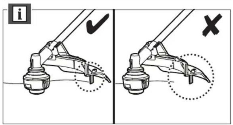


flowchart
graph TD
    A["Start"] --> B{Check}
    B -->|✓| C["Step 1"]
    B -->|✓| D["Step 2"]
    C --> E["Action: Arrow to target"]
    D --> F["Action: Arrow to target with X mark"]

natural_image
Illustration of a manual tool sweeping grass near a slope (no text or symbols)

natural_image
Diagram of a mechanical component with an arrow indicating rotation or motion (no text or symbols)


flowchart
graph TD
    A["Start"] --> B{Condition}
    B -->|✓| C["Move to a hand"]
    B -->|✓| D["Move to a tool"]
    C --> E["Loop cycle"]
    D --> F["Loop cycle"]
    E --> G["End"]
    F --> H["End"]

natural_image
Technical line drawing of a mechanical engine component with no visible text or symbols


natural_image
Diagram showing two mechanical arms with a curved arrow indicating motion or force (no text or symbols)
flowchart
graph TD
    A["1: Luggage"] --> B["2: Lock"]
    B --> C["3: Pressure Gauge"]
    C --> D["4: Screw"]
    D --> E["≥25Nm Diameter"]
    style A fill:#f9f,stroke:#333
    style B fill:#ccf,stroke:#333
    style C fill:#cfc,stroke:#333
    style D fill:#fcc,stroke:#333
    style E fill:#ffc,stroke:#333
natural_image
Diagram showing two mechanical lever mechanisms with a curved arrow indicating motion (no text or symbols present)

natural_image
Diagram of a computer monitor with a shopping cart icon, showing airflow and control arrows (no text or symbols)

flowchart
graph TD
    A["Shopping Cart"] --> B["Recycle Bin"]
    B --> C["Recycle Bin"]
    C --> D["Recycle Bin"]


flowchart
graph TD
    A["Step 1: Lock and Gear"] --> B["Step 2: Capture and Lock"]
    B --> C["Step 3: Capture and Gear"]

flowchart
graph TD
    A["1: Handover"] --> B["2: Pickup & Lock"]
    B --> C["3: Upgrade & Lock"]
    C --> D["4: Return to Product"]
natural_image
Diagram showing a car interior with dashboard and dashboard components, connected to a device panel (no text or symbols present)


natural_image
Diagram of a showerhead emitting light rays, showing internal structure and spray pattern (no text or symbols)


natural_image
Diagram of a mechanical device with a brush and sparkles, no visible text or symbols


natural_image
Illustration of a cleaning brush applying paint to a cleaning machine, with sparkles indicating texture and color (no text or symbols)


natural_image
Illustration of a hand holding a tool with sparkles, showing internal components and motion (no text or symbols)
natural_image
Cross-sectional diagram of a mechanical device with internal components and a tool, no visible text or symbols


natural_image
Diagram of a mechanical component with an arrow indicating motion, no text or symbols present
TROUBLESHOOTING
IF THESE SOLUTIONS DO NOT SOLVE THE PROBLEM, CONTACT AN AUTHORISED SERVICE CENTRE.
| Problem Possible cause Solution | ||
| Engine will not start 1. No spark 1. | The spark plug may be damaged. Remove it and check fordirt and cracks. Replace with a new spark plug. | |
| 2. No fuel 2. Push the primer bulb until bulb is full of fuel. If bulb does notfill, the primary fuel delivery sys tem is blocked. Contact anauthorised service centre. If the prim er bulb fills, the engine maybe flooded. Proceed to the next item. | ||
| 3. Engine is flooded 3. Remove the spark plug. Turn the product so the spark plughole is aimed at the ground. Rotate the choke dial to “” position and then pull the starter cord 10 to 15 times. Thiswill clear the excess fuel from the en gine. Remove any fuelsplashed on the product. Clean and reinstall the spark plug.Clean any spilled fuel and move at least 9 m away beforerestarting. Pull the starter three times with choke dial at “”. Ifthe en gine does not start, rotate the choke dial to “” positionand then repeat the normal starting pro ce dure. If the enginestill fails to start, repeat the pro ce dure with a new spark plug. | ||
| 4. Starter rope now harder to pullthan when new | 4. Contact an authorised service centre. | |
| 5. Old fuel 5. Only use fresh fuel mixed with recommended oil. Fuel over 30days old may prevent the product from starting. | ||
| Engine starts but will not accelerate | Engine requires approximatelythree minutes to warm up | Allow the engine to completely warm up. If engine does notaccelerate after three minutes, an authorised service centre. |
| Engine starts but will only run athigh speed at half choke | Carburetor requires adjustment | Contact an authorised service centre. |
| Engine does not reach full speedand emits ex ces sive smoke. | 1. Check the lubricant fuel mixture | 1. Use fresh fuel and the correct 2-stroke lubricant mix. |
| 2. Air filter is dirty | 2. Clean air filter. Refer to “Cleaning the Air Filter” in this manual. | |
| 3. Spark arrestor screen is dirty | 3. Contact an authorised service centre. | |
| Engine starts, runs, and acceleratesbut will not idle | Idle speed screw on carburetorrequires adjustment | Contact an authorised service centre. |
| Line will not advance | 1. Line is welded to itself | 1. Lubricate with silicone spray. |
| 2. Not enough line on the spool | 2. Install more line. Refer to “Line Replacement” in this manual. | |
| 3. Line is worn too short | 3. Pull the lines while alternately pressing down on and releasingthe bump head. | |
| 4. Line is tangled on spool | 4. Remove the line from the spool and rewind. Refer to “LineReplacement” in this manual. | |
| 5. Engine speed is too slow | 5. Advance the line at full throttle. | |
| Grass wraps round shaft housingand bump head | 1. Cutting tall grass at ground level | 1. Cut tall grass from the top down. |
| 2. Operating the product at partthrottle | 2. Operate the product at full throttle. | |
| Bump knob hard to turn | Screw threads are dirty or damaged | Clean the threads and lubricate with grease. If there is noimprovement, replace the bump knob. |
| Lubricant drips from muffler | 1. Operating the product at partthrottle. | 1. Operate the product at full throttle. |
| 2. Lubricant/fuel mixture is dirty 2. Use fresh fuel and correct synthetic 2-stroke lubricant mix. | ||
| 3. Air filter is dirty | 3. Clean the air filter per instruction in “Maintenance” section. | |


GUIDE DE DÉPANNAGE
SI CES SOLUTIONS NE RÉSOLVENT PAS LE PROBLÈME, CONTACTEZ VOTRE SERVICE APRÈS-VENTE AGRÉÉ.
The declared vibration value has been measured with a standard test method and may be used to compare one tool with another.
The declared vibration value may be used in a preliminary assessment of exposure.
The vibration emission during actual use of power tool can differ from the declared total value depending on the ways in which the tool is used.
Identify safety measures to protect yourself based on an estimation of exposure in the actual conditions of use, taking account of all parts of the operating cycle such as the times when the tool is switched off and when it is running idle in addition to the trigger time.
In addition to any statutory rights resulting from the purchase, this product is covered by a guarantee as stated below.
- The warranty period is 24 months for consumers and commences on the date when the product was purchased. This date has to be documented by an invoice or other proof of purchase. The product is designed and dedicated to consumer and private use only. So there is no warranty provided in case of professional or commercial use.
- There is a possibility to extend for a part of the range of garden tools (AC/DC) the warranty period over the period described above using the registration on the www.ryobitools.eu website. The eligibility of the tools for extension of the warranty period is clearly displayed in stores and / or on packaging / and contained within the product documentation. The end user needs to register his/her newly-acquired tools online within 30 days from the date of purchase. The end user may register for the extended warranty in his country of residence if listed on the online registration form where this option is valid. Furthermore, end users must give their consent to the storage of the data that are required to be entered online, and they have to accept the terms and conditions. The registration confirmation receipt, which is sent out by e-mail, and the original invoice showing the date of purchase will serve as proof of the extended warranty.
- The warranty covers all defects of the product during the warranty period due to defaults in workmanship or material at the purchase date. The warranty is limited to repair and/or replacement and does not include any other obligations including but not limited to incidental or consequential damages. The warranty is not valid if the product has been misused, used contrary to the instruction manual, or being incorrectly connected. This warranty does not apply to:
– any damage to the product that is the result of improper maintenance –any product that has been altered or modified
– any product where original identification (trade mark, serial number) markings have been defaced, altered or removed
-any damage caused by non-observance of the instruction manual
-any non CE product
– any product that has been attempted to be repaired by a non-qualified professional or without prior authorization by Techtronic Industries
– any product connected to improper power supply (amps, voltage, frequency)
— any product used with inappropriate fuel mixture (fuel, oil, percentage of oil)
– any damage caused by external influences (chemical, physical, shocks) or foreign substances
—normal wear and tear spare parts
-inappropriate use, overloading of the tool
-use of non-approved accessories or parts
—Any periodic adjustments to or maintenance cleaning of carburetors
Components (parts and accessories) subject to natural wear and tear, including but not limited to bump knobs, drive belts, clutch, blades of hedge trimmers or lawn mowers, harness, cable throttle, carbon brushes, power cord, tines, felt washers, hitch pins, blower fans, blower and vacuum tubes, vacuum bag and straps, guide bars, saw chains, hoses, connector fittings, spray nozzles, wheels, spray wands, inner reels, outer spools, cutting lines, spark plugs, air filters, gas filters, mulching blades, etc.
- For servicing, the product must be sent or presented to a RYOBI authorized service station listed for each country in the following list of service station addresses. In some countries your local RYOBI dealer undertakes to send the product to the RYOBI service organisation. When sending a product to a RYOBI service station, the product should be safely packed without any dangerous contents such as petrol, marked with sender's address and accompanied by a short description of the fault.
- A repair / replacement under this warranty is free of charge. It does not constitute an extension or a new start of the warranty period. Exchanged parts or tools become our property. In some countries delivery charges or postage will have to be paid by the sender. Your statutory rights arising from the purchase of the tool remain unaffected
- This warranty is valid in the European Community, Switzerland, Iceland, Norway, Liechtenstein, Turkey and Russia. Outside these areas, please contact your authorized RYOBI dealer to determine if another warranty applies.
AUTHORISED SERVICE CENTRE
To find an authorised service centre near you, visit http://uk.ryobitools.eu/header/service-and-support/service-agents.
FR RYOBI® CONDITIONS D'APPLICATION DE LA GARANTIE
EN EC DECLARATION OF CONFORMITY
Techtronic Industries GmbH
Max-Eyth-Straße 10, 71364 Winnenden, Germany
Herewith we declare that the product
Petrol Brushcutter/Grass trimmer
Brand: Ryobi
Model number: RBC31SESO/RBC31SBO
Serial number range:
RBC31SESO-44499001000001-44499001999999
RBC31SBO -44499101000001-44499101999999
is in conformity with the following European Directives and harmonised standards 2006/42/EC, 2014/30/EU, 2000/14/EC, 2005/88/EC, 97/68/EC as last amended 2012/46/EU,
EN ISO 11806-1:2011, EN ISO 14982:2009, EN ISO 3744:2010
Measured sound power level: 111.3 dB(A)
Guaranteed sound power level: 113 dB(A)
Conformity assessment method to Annex V Directive 2000/14/EC amended by 2005/88/EC.


Floyd Jeffrey Nesom (BSME)
Senior Director of Engineering
Winnenden, Dec. 9, 2016
Authorised to compile the technical file:
Alexander Krug, Managing Director
Techtronic Industries GmbH
Max-Eyth-Straße 10, 71364 Winnenden, Germany
Max-Eyth-Straße 10, 71364 Winnenden, Germany
Winnenden, Dec. 9, 2016
Alexander Krug, Managing Director
Techtronic Industries GmbH
Max-Eyth-Straße 10, 71364 Winnenden, Germany
FR DÉCLARATION DE CONFORMITÉ EC
Techtronic Industries GmbH
Max-Eyth-Straße 10, 71364 Winnenden, Germany
Winnenden, Dec. 9, 2016
Alexander Krug, Managing Director
Techtronic Industries GmbH
Max-Eyth-Straße 10, 71364 Winnenden, Germany
Max-Eyth-Straße 10, 71364 Winnenden, Germany
Winnenden, Dec. 9, 2016
Alexander Krug, Managing Director
Techtronic Industries GmbH
Max-Eyth-Straße 10, 71364 Winnenden, Germany


Max-Eyth-Straße 10, 71364 Winnenden, Germany
Winnenden, Dec. 9, 2016
Alexander Krug, Managing Director
Techtronic Industries GmbH
Max-Eyth-Straße 10, 71364 Winnenden, Germany

Max-Eyth-Straße 10, 71364 Winnenden, Germany
Director Sénior de Engenharia
Winnenden, Dec. 9, 2016
Alexander Krug, Managing Director
Techtronic Industries GmbH
Max-Eyth-Straße 10, 71364 Winnenden, Germany

EC CONFORMITEITSVERKLARING
Techtronic Industries GmbH
Max-Eyth-Straße 10, 71364 Winnenden, Germany
Winnenden, Dec. 9, 2016
Alexander Krug, Managing Director
Techtronic Industries GmbH
Max-Eyth-Straße 10, 71364 Winnenden, Germany

EC OVERENSSTEMMELSESERKLAERING
Techtronic Industries GmbH
Max-Eyth-Straße 10, 71364 Winnenden, Germany
Vi erklærer hermed, at produktet
Benzinbaseret Hækkeklipper/Graestrimmer
Brand: Ryobi
Modelnummer: RBC31SESO/RBC31SBO
Serienummerområde:
RBC31SESO-44499001000001-44499001999999
RBC31SBO -44499101000001-44499101999999
Winnenden, Dec. 9, 2016
Alexander Krug, Managing Director
Techtronic Industries GmbH
Max-Eyth-Straße 10, 71364 Winnenden, Germany

SV EC-DEKLARATION ANGÄENDE ÖVERENSSTÄMMIGHET
Techtronic Industries GmbH
Max-Eyth-Straße 10, 71364 Winnenden, Germany
Senior Director of Engineering
Winnenden, Dec. 9, 2016
Alexander Krug, Managing Director
Techtronic Industries GmbH
Max-Eyth-Straße 10, 71364 Winnenden, Germany
NO EC-ERKLÆRING OM PRODUKTOVERENSSTEMMELSE
Techtronic Industries GmbH
Max-Eyth-Straße 10, 71364 Winnenden, Germany
Winnenden, Dec. 9, 2016
Alexander Krug, Managing Director
Techtronic Industries GmbH
Max-Eyth-Straße 10, 71364 Winnenden, Germany
FI EC-SÄÄNNÖSTEN NOUDATTAMINEN
Techtronic Industries GmbH
Max-Eyth-Straße 10, 71364 Winnenden, Germany
Winnenden, Dec. 9, 2016
Alexander Krug, Managing Director
Techtronic Industries GmbH
Max-Eyth-Straße 10, 71364 Winnenden, Germany
Max-Eyth-Straße 10, 71364 Winnenden, Germany
Winnenden, Dec. 9, 2016
Alexander Krug, Managing Director
Techtronic Industries GmbH
Max-Eyth-Straße 10, 71364 Winnenden, Germany


DEKLARACJA ZGODNOŚCI EC
Techtronic Industries GmbH
Max-Eyth-Straße 10, 71364 Winnenden, Germany
Winnenden, Dec. 9, 2016
Alexander Krug, Managing Director
Techtronic Industries GmbH
Max-Eyth-Straße 10, 71364 Winnenden, Germany

EC IZJAVA O USKLAĐENOSTI
Techtronic Industries GmbH
Max-Eyth-Straße 10, 71364 Winnenden, Germany
Winnenden, Dec. 9, 2016
Alexander Krug, Managing Director
Techtronic Industries GmbH
Max-Eyth-Straße 10, 71364 Winnenden, Germany

PROHLÁŠENÍ O SHODĚ EC
Techtronic Industries GmbH
Max-Eyth-Straße 10, 71364 Winnenden, Germany
Winnenden, Dec. 9, 2016
Alexander Krug, Managing Director
Techtronic Industries GmbH
Max-Eyth-Straße 10, 71364 Winnenden, Germany

DECLARATIE DE CONFORMITATE EC
Techtronic Industries GmbH
Max-Eyth-Straße 10, 71364 Winnenden, Germany
Winnenden, Dec. 9, 2016
Alexander Krug, Managing Director
Techtronic Industries GmbH
Max-Eyth-Straße 10, 71364 Winnenden, Germany


EC ATBILSTIBAS PAZINOJUMS
Techtronic Industries GmbH
Max-Eyth-Straße 10, 71364 Winnenden, Germany
Winnenden, Dec. 9, 2016
Alexander Krug, Managing Director
Techtronic Industries GmbH
Max-Eyth-Straße 10, 71364 Winnenden, Germany

EC VASTAVUSDEKLARATSIOON
Techtronic Industries GmbH
Max-Eyth-Straße 10, 71364 Winnenden, Germany
Kinnitame, et see toode
Winnenden, Dec. 9, 2016
Alexander Krug, Managing Director
Techtronic Industries GmbH
Max-Eyth-Straße 10, 71364 Winnenden, Germany

EC ATITIKTIES DEKLARACIJA
Techtronic Industries GmbH
Max-Eyth-Straße 10, 71364 Winnenden, Germany
Winnenden, Dec. 9, 2016
Alexander Krug, Managing Director
Techtronic Industries GmbH
Max-Eyth-Straße 10, 71364 Winnenden, Germany

EC IZJAVA O USKLAĐENOSTI
Techtronic Industries GmbH
Max-Eyth-Straße 10, 71364 Winnenden, Germany
2006/42/EC, 2014/30/EU, 2000/14/EC, 2005/88/EC, 97/68/EC prema
Winnenden, Dec. 9, 2016
Alexander Krug, Managing Director
Techtronic Industries GmbH
Max-Eyth-Straße 10, 71364 Winnenden, Germany


IZJAVA EC O SKLADNOSTI
Techtronic Industries GmbH
Max-Eyth-Straße 10, 71364 Winnenden, Germany
Winnenden, Dec. 9, 2016
Alexander Krug, Managing Director
Techtronic Industries GmbH
Max-Eyth-Straße 10, 71364 Winnenden, Germany

Max-Eyth-Straße 10, 71364 Winnenden, Germany
Winnenden, Dec. 9, 2016
Alexander Krug, Managing Director
Techtronic Industries GmbH
Max-Eyth-Straße 10, 71364 Winnenden, Germany

PREHLÁSENIE O ZHODE EC
Techtronic Industries GmbH
Max-Eyth-Straße 10, 71364 Winnenden, Germany
Winnenden, Dec. 9, 2016
Alexander Krug, Managing Director
Techtronic Industries GmbH
Max-Eyth-Straße 10, 71364 Winnenden, Germany

Max-Eyth-Straße 10, 71364 Winnenden, Germany
Winnenden, Dec. 9, 2016
Max-Eyth-Straße 10, 71364 Winnenden, Germany


EC UYGUNLUK BEYANI
Techtronic Industries GmbH
Max-Eyth-Straße 10, 71364 Winnenden, Germany
Winnenden, Dec. 9, 2016
Max-Eyth-Straße 10, 71364 Winnenden, Germany
RYOBI®
Techtronic Industries GmbH
Max-Eyth-Straße 10,
71364 Winnenden, Germany


- INTENDED USE
- WARNING
- GENERAL SAFETY WARNINGS
- GRASS TRIMMER SAFETY WARNINGS
- BRUSHCUTTER SAFETY WARNINGS
- ASSEMBLY
- | English
- USING THE REELEASY™ GRASS TRIMMER HEAD AND TRI-ARC™ BLADE
- OPERATION
- FUELING AND REFUELING
- FILLING THE TANK
- STARTING THE ENGINE USING AN ELECTRICAL STARTER (OPTIONAL):
- TRANSPORTATION AND STORAGE
- SHORT TERM
- MAINTENANCE
- RESIDUAL RISKS
- RISK REDUCTION
- KNOW YOUR PRODUCT
- SYMBOLS ON THE PRODUCT
- DANGER
- CAUTION
- SYMBOLS IN THIS MANUAL
- SYMBOLES APPLIQUÉS SUR LE PRODUIT
- MACHEN SIE SICH MIT IHREM PRODUKT VERTRAUT
- SYMBOLE AUF DEM PRODUKT
- COMBUSTIBLE Y REPOSTAJE
- ALGEMENE VEILIGHEIDSWAARSCHUWINGEN
- VEILIGHEIDSWAARSCHUWINGEN VOOR DE
- BRÆNDSTOF OG OPTANKNING
- SYMBOLER PÅ PRODUKTET
- TRANSPORT OCH FÖRVARING
- FÖRVARING PÅ KORT SIKT
- SYMBOLER PÅ PRODUKTEN
- KJENN PRODUKTET DITT
- OBOZNÁMTE SA S VAŠÍM PRODUKTOM
- TROUBLESHOOTING
- GUIDE DE DÉPANNAGE
- AUTHORISED SERVICE CENTRE
- FR RYOBI® CONDITIONS D'APPLICATION DE LA GARANTIE
- EN EC DECLARATION OF CONFORMITY
- FR DÉCLARATION DE CONFORMITÉ EC
- EC CONFORMITEITSVERKLARING
- EC OVERENSSTEMMELSESERKLAERING
- SV EC-DEKLARATION ANGÄENDE ÖVERENSSTÄMMIGHET
- NO EC-ERKLÆRING OM PRODUKTOVERENSSTEMMELSE
- FI EC-SÄÄNNÖSTEN NOUDATTAMINEN
- DEKLARACJA ZGODNOŚCI EC
- EC IZJAVA O USKLAĐENOSTI
- PROHLÁŠENÍ O SHODĚ EC
- DECLARATIE DE CONFORMITATE EC
- EC ATBILSTIBAS PAZINOJUMS
- EC VASTAVUSDEKLARATSIOON
- EC ATITIKTIES DEKLARACIJA
- IZJAVA EC O SKLADNOSTI
- PREHLÁSENIE O ZHODE EC
- EC UYGUNLUK BEYANI
Brand : RYOBI
Model : RBC31SBO
Category : String trimmers