HTVC400 - Vacuum Cleaner Hillvert - Free user manual and instructions
Find the device manual for free HTVC400 Hillvert in PDF.
| Product Type | Cordless Pool Cleaner |
| Brand | Hillvert |
| Model | HTVC400 |
| Rated Voltage | 18 V~ |
| Rated Power | 40 W |
| Battery Type | Lithium-ion (model D170-507A) |
| Charger | XH2150-1500WG, input 230 V / 50 Hz / 0.8 A, output 21.5 V / 1.5 A |
| Runtime | 50 to 60 minutes after full charge |
| Initial Charging Time | 1.5 hours |
| Maximum Water Temperature | 35 °C |
| Dimensions (L x W x H) | 172 x 240 x 830 mm |
| Weight | 1.94 kg |
| Protection Class | II |
| Filter Type | Filter net (net ring) |
| Recommended Use | Pools and spas up to 35°C |
| Main Functions | Suction of sediment, leaves, hair, sand |
| Maintenance | Rinse the filter after each use, drain and dry in winter |
| Safety | ON/OFF switch, do not use when people are in the water |
| Spare Parts | Battery, charger, filter net, key, handle, pump |
| Package Contents | Cleaner, charger, filter net, handle, key, pump |
Frequently Asked Questions - HTVC400 Hillvert
User questions about HTVC400 Hillvert
0 question about this device. Answer the ones you know or ask your own.
Ask a new question about this device
Download the instructions for your Vacuum Cleaner in PDF format for free! Find your manual HTVC400 - Hillvert and take your electronic device back in hand. On this page are published all the documents necessary for the use of your device. HTVC400 by Hillvert.
USER MANUAL HTVC400 Hillvert
text_image
Technical diagram of a vacuum cleaner with numbered parts labeled 1 through 8text_image
Technical diagram showing three-step assembly of a vacuum cleaner with labeled parts 1, 2, and 3.1- Drecksauger
2- Pumpe
3- Griff
text_image
Diagram of a vacuum cleaner in water with labeled components and flow direction1- Schalter
text_image
Technical diagram of a handheld device with numbered components for identification1- Maulschlüssel
2- Obere Klappe
3- Untere Klappe
4- Filternetz
natural_image
Line drawing of a vacuum cleaner with attached clamp and labeled component (no text or symbols)1-Ladegerät
This User Manual has been translated using machine translation. We have made every effort to ensure the translation is accurate, but please note that automated translations are not perfect and are not meant to replace human translators. The official version of the User Manual is in English. Any differences between the translated version and the original English are not legally binding. If you have any questions about the accuracy of the translation, please refer to the English version, which is the official reference. More language versions are available upon request via info@expondo.com.
Technical data
| Parameter description Parameter value | |
| Product name Cordless Pool Vacuum Cleaner | |
| Model | HT-VC-400 |
| Rated voltage [V~] 18 | |
| Rated power [W] 40 | |
| IP | X8 |
| Battery | D170-507A |
| Used with Battery charger XH2150-1500WG | |
| Input of Battery Charger [V~] / Hz / A 230 / 50 / 0.8 | |
| Output of Battery Charger [V~] / A 21.5 / 1.5 | |
| Max. Water Temp [°C] 35 | |
| Protection class | II |
| Dimensions [width * length * height; mm] 172*240*830 | |
| Weight [kg] 1.94 | |
1. General description
The user manual is designed to assist in the safe and trouble-free use of the device. The product is designed and manufactured in accordance with strict technical guidelines, using state-of-the-art technologies and components. Additionally, it is produced in compliance with the most stringent quality standards.
DO NOT USE THE DEVICE UNLESS YOU HAVE THOROUGHLY READ AND UNDERSTOOD THIS USER MANUAL.
To increase the product life of the device and to ensure trouble-free operation, use it in accordance with this user manual and regularly perform maintenance tasks. The technical data and specifications in this user manual are up to date. The manufacturer reserves the right to make changes associated with quality improvement. The device is designed to reduce noise emission risks to a minimum, taking into account technological progress and noise reduction opportunities.
Legend
 | The product satisfies the relevant safety standards. |
 | Read instructions before use. |
 | The product must be recycled. |
 | WARNING! or CAUTION! or REMEMBER! Applicable to the given situation.(general warning sign) |
 | ATTENTION! Electric shock warning! |

⚠️ATTENTION! Read all safety warnings and all instructions. Failure to follow the warnings and instructions may result in electric shock, fire and/or serious injury or even death.
The terms "device" or "product" are used in the warnings and instructions to refer to:
Cordless Pool Vacuum Cleaner
1.1. Electrical safety
a) The plug must fit the socket. Do not modify the plug in any way. Using original plugs and matching sockets reduces the risk of electric shock.
b) Avoid touching earthed elements such as pipes, heaters, boilers, and refrigerators. There is an increased risk of electric shock if the earthed device is exposed to rain, comes into direct contact with a wet surface, or is operating in a damp environment. Water getting into the device increases the risk of damage to the device and of electric shock.
c) Do not touch the device with wet or damp hands when it is connected to the charger.
d) Use the cable only for its designated use. Never use it to carry the device or to pull the plug out of a socket. Keep the cable away from heat sources, oil, sharp edges, or moving parts. Damaged or tangled cables increase the risk of electric shock.
e) Discontinue use if the power cord or adapter is damaged or shows signs of wear. A damaged power supply must be replaced. A damaged power cord should be replaced by a qualified electrician or the manufacturer's service center.
f) Do not use the product when there are people in the water.
g) When charging, make sure that the appliance is plugged into a socket in a place where there is no risk of flooding, and which is protected against moisture.
h) Turn off the product before charging.
i) Only use the original charger to charge the device.
j) When charging, the device should be in a clean, dry, and well-ventilated room.
k) Make sure the device and charger are dry before charging.
1.2. Safety in the workplace
a) Make sure the workplace is clean and well lit. A messy or poorly lit workplace may lead to accidents. Try to think ahead, observe what is going on and use common sense when working with the device.
b) Do not use the device in a potentially explosive environment, for example in the presence of flammable liquids, gases or dust. The device generates sparks which may ignite dust or fumes.
c) If you are unsure whether the product is operating correctly or if you find damage, please contact the manufacturer's service center.
d) Only the manufacturer's service center may make repairs to the product. Do not attempt to make repairs yourself!
e) In case of fire, use a powder or carbon dioxide (CO2) fire extinguisher (one intended for use on live electrical devices) to put it out.
f) Use the device in a well-ventilated space.
g) Please keep this manual available for future reference. If this device is passed on to a third party, the manual must be passed on with it.
h) Keep packaging elements and small assembly parts in a place not available to children.
i) Keep the device away from children and animals.
j) If this device is used together with another equipment, the remaining instructions for use shall also be followed.

Remember! When using the device, protect children and other bystanders.
1.3. Personal safety
a) Do not use the device when tired, ill or under the influence of alcohol, narcotics or medication which can significantly impair the ability to operate the device.
b) The device is not designed to be handled by people (including children) with limited mental and sensory functions or persons lacking relevant experience and/or knowledge unless they are supervised by a person responsible for their safety or they have received instruction on how to operate the device.
c) When working with the device, use common sense and stay alert. Temporary loss of concentration while using the device may lead to serious injuries.
d) Do not wear loose clothing or jewelry. Keep hair, clothes and gloves away from moving parts. Loose clothing, jewelry or long hair may get caught in moving parts.
e) The device is not a toy. Children must be supervised to ensure that they do not play with the device.
f) Do not put your hands or other items inside the device while it is in use!
1.4. Safe device use
a) Do not overload the device. Use the appropriate tools for the given task. A correctly-selected device will perform the task for which it was designed better and in a safer manner.
b) Do not use the device if the ON/OFF switch does not function properly (does not switch the device on and off). Devices which cannot be switched on and off using the ON/OFF switch are hazardous, should not be operated and must be repaired.
c) Make sure the plug is disconnected from the socket before attempting any adjustments, accessory replacements or before putting the device aside. Such precautions will reduce the risk of accidentally activating the device.
d) When not in use, store in a safe place, away from children and people not familiar with the device who have not read the user manual. The device may pose a hazard in the hands of inexperienced users.
e) Keep the device in perfect technical condition. Before each use check for general damage and especially check for cracked parts or elements and for any other conditions which may impact the safe operation of the device. If damage is discovered, hand over the device for repair before use.
f) Keep the device out of the reach of children.
g) Device repair or maintenance should be carried out by qualified people, only using original spare parts. This will ensure safe use.
h) To ensure the operational integrity of the device, do not remove factory-fitted guards and do not loosen any screws.
i) Avoid situations where the device stops working during use due to excessive loading. This may result in overheating of the drive elements and damage to the device.
j) Do not touch articulated parts or accessories unless the device has been disconnected from the power source.
k) Clean the device regularly to prevent stubborn grime from accumulating.
I) The device is not a toy. Cleaning and maintenance may not be carried out by children without supervision by an adult person.
m) It is forbidden to interfere with the structure of the device to change its parameters or construction.
n) Keep the device away from sources of fire and heat.
o) Please avoid using the device to clean sharp objects, otherwise the device and the filter will be damaged.
p) Do not allow to run dry and do not use the product with the inlet completely closed.
q) The product can work with water temperature from 4^ C to 35^ C.
r) To avoid unnecessary damage or injury, keep hair, jewelry, body parts, or clothing away from the inlet as it generates suction when the device is in operation.
s) The device must not be used to purify flammable or explosive liquids.

ATTENTION! Despite the safe design of the device and its protective features, and despite the use of additional elements protecting the operator, there is still a slight risk of accident or injury when using the device. Stay alert and use common sense when using the device.
2. Use guidelines
The product is designed to remove sediment, leaves, hair, sand, and other debris from water up to 35 °C . This enables cleaning of heated pools or hot tubs without the need to cool the water.
The user is liable for any damage resulting from unintended use of the device.
2.1. Device description
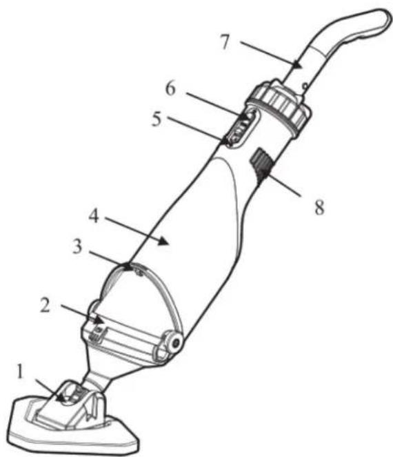
text_image
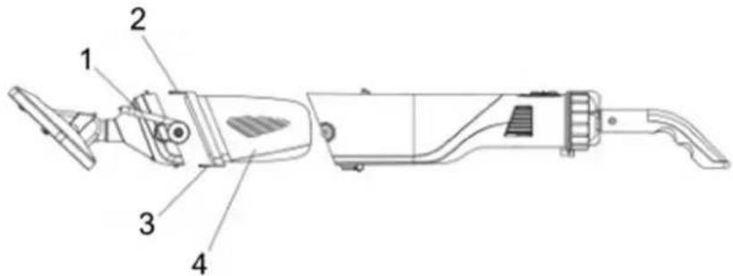
Technical diagram of a vacuum cleaner with numbered parts labeled 1 through 8| Part number Description | |
| 1 | Dirt |
| 2 Filter net ring | |
| 3 | Wrench |
| 4 | Main |
| 5 | Charging |
| 6 | Switch |
| 7 | Handle |
| 8 | Outlet |
sucker
pump interface
2.2. Preparing for use
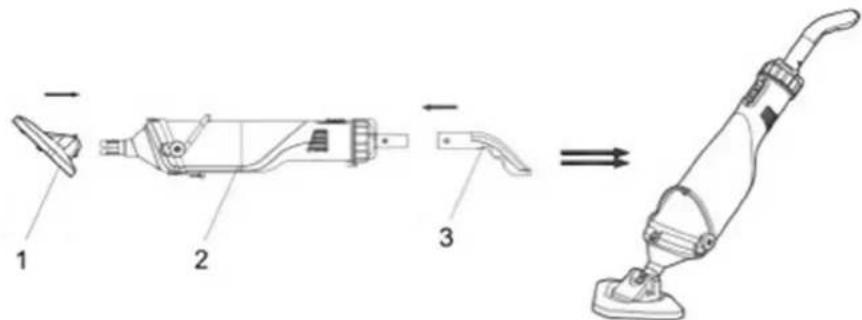
To assemble a complete machine, the handle and dirt sucker should be installed into the pump in order as the figure shows.
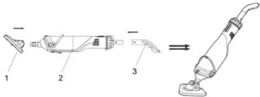
text_image
Technical diagram showing three-step assembly of a vacuum cleaner with labeled parts 1, 2, and 3.1- Dirt sucker
2- Pump
3- Handle
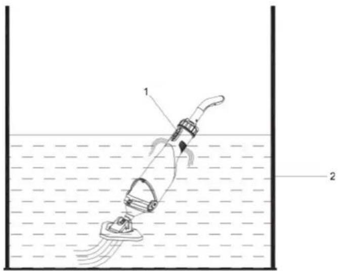
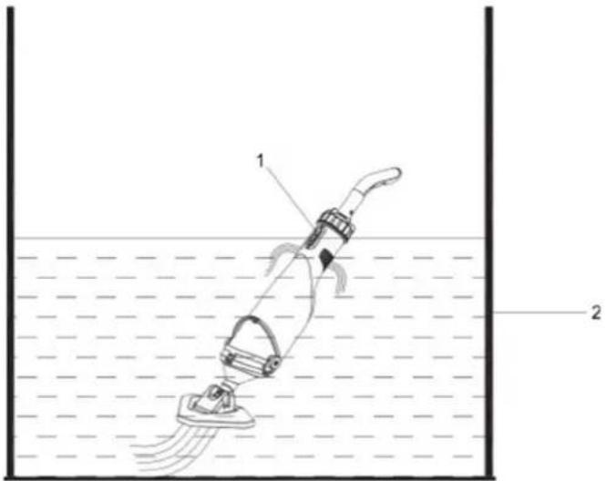
Push down the switch to turn on the cleaner. The distance between the priming water level and the horizontal surface should be 30cm.

text_image
Diagram of a vacuum cleaner in water with labeled components and fluid flow indicators1- Switch
2- Priming water level is 30cm. When cleaning the filter net, please open the wrench, the upper and lower hasps attached to the filter net, take out the waste in the filter net, and rinse it.
2.3. Device use
text_image
Technical diagram of a handheld device with numbered parts labeled 1 to 41- Wrench
2- Upper hasp
3- Lower hasp
4- Filter net
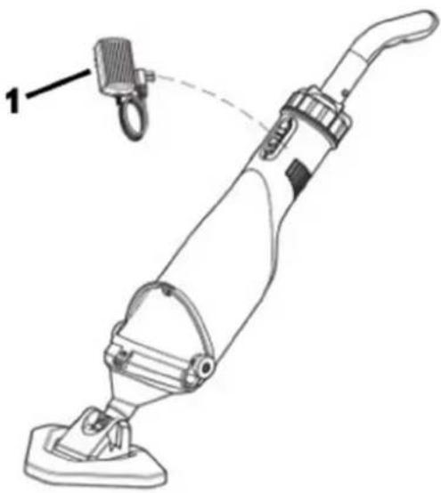
Connect the charger with the product as the figure shows. The specification of the charger: Input 230V, 50Hz, 0.8A; Output 21VDC, 1.5A.
During the charging process, if the indicator light turns red, it means the battery is charging; if the indicator light turns green, it means the product is fully charged. Before the first use, please charge the product for 1.5 hours. After being fully charged, the product can work for 50-60 minutes.
natural_image
Line drawing of a vacuum cleaner with attached hook and labeled component (no text or symbols)1-Charger
2.4. Cleaning and maintenance
- The product is basically maintenance free. To ensure a long service life, however, we recommend regular checks and care.

WARNING! Before every servicing, switch off the product.
- If the product is not going to be used for a long time or has to be removed for the winter months, rinse it out with water, empty it completely, and allow it to dry.
- If there is a risk of frost, the product must be emptied completely.
- After long stoppages, make sure the rotor turns correctly by briefly switching the product on and off.
Disposing of used devices
Do not dispose of this device in municipal waste systems. Hand it over to an electric and electrical device recycling and collection point. Check the symbol on the product, instruction manual, and packaging. The plastics used to construct the device can be recycled following their markings. By choosing to recycle you are making a significant contribution to the protection of our environment.
Contact local authorities for information on your local recycling facility.
2.5. Troubleshooting
In most cases, you will be able to troubleshoot problems easily by yourself.
| Problem | Possible cause | Solution |
| Fail to clean the waste. | The battery runs out. | Recharge the product, and it can work for 50-60 minutes after being fully charged. |
| The impeller is damaged. | Repair or replace the impeller. | |
| The impeller is blocked. | Turn off the product and check the impeller. | |
| The filter bag is full. | Clean the waste in the filter bag. | |
| Waste gets out from the front parts. | Check whether the valve is damaged. | Change the check valve. |
| Waste gets out from the filter net. | The filter net is damaged. | Change the filter net. |
| The handle/extension pole fails to connect. | The connective V-Cord is damaged. | Change the V-Cord. |
| The product fails to be charged. | The battery is damaged. | Correspond with the dealer to replace the battery. Warning! To avoid damaging the cleaner, please purchase the original lithium battery to replace it. |
| The charger is damaged. | Replace the charger. Warning! To avoid damaging the product caused by the charger, please purchase the original charger to replace it. |

text_image
Technical diagram of a vacuum cleaner with numbered parts labeled 1 through 8text_image
Technical diagram showing three-step assembly of a vacuum cleaner with labeled parts 1, 2, and 3.1- Odkurzacz brudu
2- Pompka
3- Uchwyt
text_image
Diagram of a vacuum cleaner in water with labeled components and flow direction1- Przełącznik
text_image
Technical diagram of a handheld device with numbered components labeled 1 to 41- Klucz płaski
2- Górny zaczep
3- Dolna klamra
natural_image
Line drawing of a vacuum cleaner with attached hook and labeled component (no text or symbols)1-tadowarka
text_image
Technical diagram of a vacuum cleaner with numbered parts for identificationtext_image
Technical diagram of a vacuum cleaner with labeled parts and assembly line1- Vysavač špíny
2- Čerpadlo
3- Držák
text_image
Diagram of a vacuum cleaner in water with labeled parts 1 and 21- Vypínač
text_image
Technical diagram of a handheld device with numbered parts labeled 1 to 4natural_image
Line drawing of a vacuum cleaner with attached hook and labeled component (no text or symbols)1-nabíječka
2.4. ČISTĚNÍ A ÚDRŽBA
text_image
Technical diagram of a vacuum cleaner with numbered parts labeled 1 through 8text_image
Technical diagram showing three-step assembly of a vacuum cleaner with labeled parts 1, 2, and 3.text_image
Diagram of a vacuum cleaner in water with labeled components and flow direction1- Commutateur
text_image
Technical diagram of a handheld device with numbered components labeled 1 to 41- Clé plate
natural_image
Line drawing of a vacuum cleaner with attached hook and labeled component (no text or symbols)1-Chargeur
text_image
Technical diagram of a vacuum cleaner with numbered parts labeled 1 through 8text_image
Technical diagram showing three stages of a vacuum cleaner assembly with labeled parts 1, 2, and 3.1- Aspirapolvere
text_image
Diagram of a water spray gun with labeled components and fluid level indicator1- Selettore
text_image
Technical diagram of a handheld device with numbered components labeled 1 to 41- Chiave piatta
2- Ganci superiori
3- Ganci inferiori
4- Rete filtrante
natural_image
Line drawing of a vacuum cleaner with attached hook and labeled component (no text or symbols)1-Caricabatterie
text_image
Technical diagram of a vacuum cleaner with numbered parts labeled 1 through 8text_image
Technical diagram showing three-step assembly of a vacuum cleaner with labeled parts 1, 2, and 3.text_image
Diagram of a vacuum cleaner in water with labeled parts 1 and 2, showing fluid flow and component placement.1- Interruptor
text_image
Technical diagram of a handheld device with numbered components labeled 1 to 41- Llave plana
2- Cerrojo superior
3- Cerrojo inferior
4- Red de filtrado
natural_image
Line drawing of a vacuum cleaner with attached hook and labeled component (no text or symbols)1-Cargador
text_image
Technical diagram of a vacuum cleaner with numbered parts labeled 1 through 8text_image
Technical diagram showing three-step assembly of a vacuum cleaner with labeled parts 1, 2, and 3.1- Dirt sucker
2- Szivattyú
3- Fogantyú
text_image
Diagram of a vacuum cleaner in water with labeled components and flow direction1- Kapcsoló
text_image
Technical diagram of a handheld device with numbered components labeled 1 to 41- Laposkulcs
2- Felső hasp
3- Alsó haspántok
4- Szürőháló
natural_image
Line drawing of a vacuum cleaner with attached hook and labeled component (no text or symbols)1-töltő
text_image
Technical diagram of a vacuum cleaner with numbered parts labeled 1 through 8text_image
Technical diagram showing three-step assembly of a vacuum cleaner with labeled parts 1, 2, and 3.1- Snavsesuger
2- Pumpe
3- Händtag
text_image
Diagram of a vacuum cleaner in water with labeled parts 1 and 2, showing internal components and fluid flow.1- Kontakt
text_image
Technical diagram of a handheld device with numbered parts labeled 1 to 41- Skruenøgle
2- ∅vre haspe
3- Nedre haspe
4- Filternet
Forbind opladeren med produktet som vist på figuren. Opladerens specifikationer: Input 230V, 50Hz, 0,8A; Output 21VDC, 1,5A.
natural_image
Line drawing of a vacuum cleaner with attached hook and labeled component (no text or symbols)1 oplader
text_image
Technical diagram of a vacuum cleaner with numbered parts labeled 1 through 8text_image
Technical diagram showing three-step assembly of a vacuum cleaner with labeled parts 1, 2, and 3.text_image
Diagram of a vacuum cleaner in water with labeled components and fluid flow indicators1- Kytkin
text_image
Technical diagram of a handheld device with numbered parts labeled 1 to 41- Jakoavain
2- Ylempi hasp
3- Alempi hasp
4- Suodatinverkko
natural_image
Line drawing of a vacuum cleaner with attached hook and labeled component (no text or symbols)1-laturi
text_image
Technical diagram of a vacuum cleaner with numbered parts for identificationtext_image
Technical diagram showing three stages of a vacuum cleaner assembly with labeled parts 1, 2, and 3.1- Vuilzuiger
2- Pomp
3- Handvat
text_image
Diagram of a vacuum cleaner in water with labeled parts 1 and 2, showing fluid flow and component placement.1- Schakelaar
text_image
Technical diagram of a handheld device with numbered parts labeled 1 to 41- Moersleutel
2- Bovenste grendel
3- Onderste grendel
4- Filternet
natural_image
Line drawing of a vacuum cleaner with attached hook and labeled component (no text or symbols)1-Oplader
text_image
Technical diagram of a vacuum cleaner with numbered parts for identification| Artikkelnummer | Beskrivelse |
| 1 | Skittsuger |
| 2 | Filternettring |
| 3 | Skiftenøkkel |
| 4 | Hovedpumpehus |
| 5 | Ladegrensesnitt |
| 6 | Bryter |
| 7 | Håndtak |
| 8 | Uttak |
text_image
Technical diagram showing three-step assembly of a vacuum cleaner with labeled parts 1, 2, and 3.1- Skittsuger
2- Pumpe
3- Händtak
Trykk ned bryteren for å slå på støvsugeren. Avstanden mellom grunningsvannstanden og den horisontale overflaten skal være 30 cm.
text_image
Diagram of a vacuum cleaner in water with labeled parts 1 and 21- Bryter
text_image
Technical diagram of a handheld device with numbered parts labeled 1 to 41- Skiftenøkkel
2- ∅vre hasp
3- Nedre hasp
4- Filternett
natural_image
Line drawing of a vacuum cleaner with attached hook and labeled component (no text or symbols)1-lader
text_image
Technical diagram of a vacuum cleaner with numbered parts for identificationtext_image
Technical diagram showing three-step assembly of a vacuum cleaner with labeled parts 1, 2, and 3.1- Smutssuger
2- Pump
3- Handtag
text_image
Diagram of a vacuum cleaner in water with labeled components and fluid flow indicators1- Växla
text_image
Technical diagram of a handheld device with numbered parts labeled 1 to 41- Rycka
2- Övre hasp
3- Nedre hasp
4- Filternät
natural_image
Line drawing of a vacuum cleaner with attached hook and labeled component (no text or symbols)1-laddare
text_image
Technical diagram of a vacuum cleaner with numbered parts labeled 1 through 8text_image
Technical diagram showing three-step assembly of a vacuum cleaner with labeled parts 1, 2, and 3.1- Sugador de sujeira
2- Bombear
3- Pega
text_image
Diagram of a vacuum cleaner in water with labeled components and flow direction1- Trocar
text_image
Technical diagram of a handheld device with numbered components labeled 1 to 41- Chave inglesa
natural_image
Line drawing of a vacuum cleaner with attached hook and labeled component (no text or symbols)1-Carregador
text_image
Technical diagram of a vacuum cleaner with numbered parts for identification| Diel č. | Popis |
| 1 | Vysávač nečistôt |
| 2 | Krúžok |
| 3 | klíč |
| 4 | Hlavné |
| 5 | Rozhranie |
| 6 | Prepínač |
| 7 | Rukovát' |
| 8 | Outlet |
text_image
Technical diagram of a vacuum cleaner with labeled parts and assembly line1- Vysávač nečistôt
2- Pumpa
3- Rukovät
text_image
Diagram of a vacuum cleaner in water with labeled parts 1 and 2, showing internal components and fluid flow.1- Prepínač
text_image
Technical diagram of a handheld device with numbered parts labeled 1 to 41- klúč
natural_image
Line drawing of a vacuum cleaner with attached hook and labeled component (no text or symbols)1-nabíjačka
text_image
Technical diagram of a vacuum cleaner with numbered parts for identificationtext_image
Technical diagram showing three-step assembly of a vacuum cleaner with labeled parts 1, 2, and 3.text_image
Diagram of a vacuum cleaner in water with labeled components and flow direction1- Превключване
text_image
Technical diagram of a handheld device with numbered components labeled 1 to 41- Гаечен ключ
natural_image
Line drawing of a vacuum cleaner with attached clamp and labeled component (no text or symbols)text_image
Technical diagram of a vacuum cleaner with numbered parts for identificationtext_image
Technical diagram showing three-step assembly of a vacuum cleaner with labeled parts 1, 2, and 3.1-Κορόιδο βρωμιάς
2- Αντλία
3- Λαβή
text_image
Diagram of a vacuum cleaner in water with labeled parts 1 and 2, showing fluid flow and component placement.1- Διακόπτης
text_image
Technical diagram of a handheld device with numbered components labeled 1 to 41- Κλειδί
2- Άνω κεφαλή
3- Χαμηλότερη λαβή
4- Δίχτυ φίλτρου
natural_image
Line drawing of a vacuum cleaner with attached clamp and labeled component (no text or symbols)1-Φορτιστής
text_image
Technical diagram of a vacuum cleaner with numbered parts labeled 1 through 8| Broj dijela Opis | |
| 1 | Usisivač prljavštine |
| 2 Mrežasti prsten filtera | |
| 3 | Ključ |
| 4 | Kućište glavne pumpe |
| 5 | Sučelje za punjenje |
| 6 | Prekidač |
| 7 | Ručka |
| 8 | Izlaz |
2.2. Priprema za upotrebu
Za sastavljanje kompletnog stroja, ručku i usisivač prljavštine treba ugraditi u pumpu redom kako prikazuje slika.
text_image
Technical diagram of a vacuum cleaner with labeled parts and assembly line1- Usisivač prljavštine
2- Pumpa
3- Ručka
text_image
Diagram of a vacuum cleaner in water with labeled components and fluid flow indicators1- Prekidač
2- Razina početne vode je 30 cm. Kada čistite mrežicu filtera, otvorite ključ, gornju i donju kopču pričvršćenu na mrežicu filtera, izvadite otpad iz mrežice filtera i isperite ga.
text_image
Technical diagram of a handheld device with numbered parts labeled 1 to 41- Ključ
2- Gornja kopča
3- Donji držač
4- Filtarska mreža
Spojite punjač s proizvodom kao što je prikazano na slici. Specifikacija punjača: Ulaz 230V, 50Hz, 0,8A; Izlaz 21VDC, 1.5A.
natural_image
Line drawing of a vacuum cleaner with attached hook and labeled component (no text or symbols)1-punjač
2.4. Čišćenje i održavanje
text_image
Technical diagram of a vacuum cleaner with numbered parts labeled 1 through 8text_image
Technical diagram showing three-step assembly of a vacuum cleaner with labeled parts 1, 2, and 3.1- Purvo siurblys
2- Siurblys
3- Rankena
text_image
Diagram of a vacuum cleaner in water with labeled components and fluid flow indicators1- Perjungti
text_image
Technical diagram of a handheld device with numbered parts labeled 1 to 4natural_image
Line drawing of a vacuum cleaner with attached hook and labeled component (no text or symbols)1-jkroviklis
text_image
Technical diagram of a vacuum cleaner with numbered parts labeled 1 through 8text_image
Technical diagram showing three-step assembly of a vacuum cleaner with labeled parts 1, 2, and 3.1- Ventitor de murdarie
2- Pompa
3- Mâner
text_image
Diagram of a vacuum cleaner in water with labeled parts 1 and 2, showing fluid flow and component placement.1- Comutator
text_image
Technical diagram of a handheld device with numbered components labeled 1 to 41- Cheie
natural_image
Line drawing of a vacuum cleaner with attached hook and labeled component (no text or symbols)1-Încărcător
text_image
Technical diagram of a vacuum cleaner with numbered parts for identificationtext_image
Technical diagram of a vacuum cleaner with labeled parts and assembly line1- Sesalec umazanije
2- Črpalka
3- Ročaj
Potisnite stikalo navzdol, da vklopite čistilec. Razdalja med vodno gladino in vodoravno površino naj bo 30 cm.
text_image
Diagram of a vacuum cleaner in water with labeled components and flow direction1- Stikalo
text_image
Technical diagram of a handheld device with numbered parts labeled 1 to 41- viličasti ključ
2- Zgornja zapora
3- Spodnja zapora
4- Filtrirna mreža
natural_image
Line drawing of a vacuum cleaner with attached hook and labeled component (no text or symbols)1-Polnilnik
For the disposal of the device please consider and act according to the national and local rules and regulations.
CONTACT
expondo Polska sp. z o.o. sp. k.