SULW1 - Wall mount SONY - Free user manual and instructions
Find the device manual for free SULW1 SONY in PDF.
| Brand | Sony |
| Model | SULW1 |
| Product Type | Wall mount for LCD TV |
| Material | Metal |
| Color | Black |
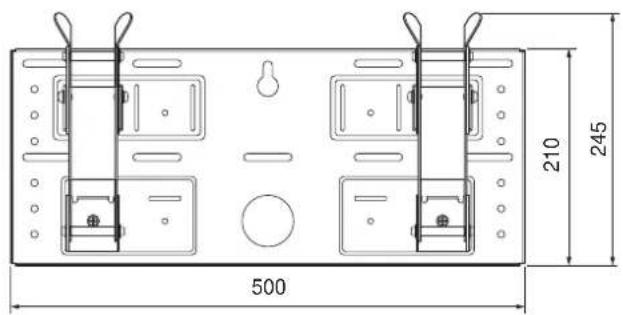
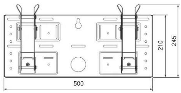
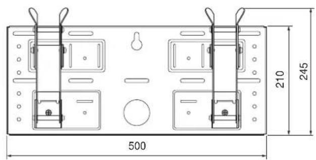
| Mounting plate dimensions | 210 x 500 mm |
| Mount weight | 3.4 kg |
| Adjustable tilt angle | 0°, 5°, 10°, 15°, 20° |
| Maximum load capacity | 23 kg (KDL-L32MRX1) |
| Minimum recommended wall load | 4 times the weight of the TV |
| Compatibility | KDL-L32MRX1, KLV-L32MRX1, KLV-30MR1, KLV-26HG2, KLV-L32M1 |
| Wall fixing type | 5 M6 screws or equivalent (not supplied) |
| Number of wall fixing points | 5 (minimum) |
| Cable routing hole | Yes, diameter 60 mm |
| Maintenance and cleaning | Clean with a soft, dry cloth. Do not use abrasive products. |
| Safety | Installation must be carried out by a qualified professional. Do not disassemble or modify parts. Do not exceed maximum load. |
| Spare parts and repairability | Parts are not user-serviceable. Contact an authorized Sony dealer. |
| General information | Designed for indoor use. Warranty: according to legal conditions. |
Frequently Asked Questions - SULW1 SONY
User questions about SULW1 SONY
0 question about this device. Answer the ones you know or ask your own.
Ask a new question about this device
Download the instructions for your Wall mount in PDF format for free! Find your manual SULW1 - SONY and take your electronic device back in hand. On this page are published all the documents necessary for the use of your device. SULW1 by SONY.
USER MANUAL SULW1 SONY
Thank you for purchasing this product.
To Customers
Sufficient expertise is required for installing this product. Be sure to subcontract the installation to Sony dealers or contractors and pay adequate attention to safety during the installation. Sony is not liable for any damages or injury caused by mishandling or improper installation. Your Statutory Rights (if any) are not affected.
WARNING
If the safety precautions are not observed and the product is used incorrectly, it may result in a fire or serious injury.
This instruction manual shows the important precautions necessary to prevent accidents and to promote the correct handling of the product. Be sure to read this instruction manual thoroughly and use the product correctly. Be sure to keep this instruction manual available for future reference.
For Sony Dealers
Sufficient expertise is required for installing this product. Be sure to read this instruction manual thoroughly to do the installation work safely. We are not liable for any damage or injury caused by mishandling or improper installation. Your Statutory Rights (if any) are not affected. Please give this manual to the customer after installation.
This Wall-Mount Bracket is designed by Sony for use with the specified product. Do not use this bracket with equipment other than the following products.
Specified products: LCD Colour TV (KDL-L32MRX1/KLV-L32MRX1/KLV-30MR1/KLV-26HG2/KLV-L32M1)
On Safety
Products by Sony are designed with safety in mind.
If the products are used incorrectly, however, it may result in a serious injury through fire, electric shock, the product toppling over, or the product dropping. Be sure to observe the precautions for safety to prevent such accidents.
For Customers
WARNING
If the following precautions are not observed, there is a possibility of either death or serious injury through a fire, an electric shock or an explosion.
Be sure to subcontract the installation to qualified contractors and keep small children away during the installation.
If persons other than qualified contractors install the Wall-Mount Bracket, the following accidents may happen.
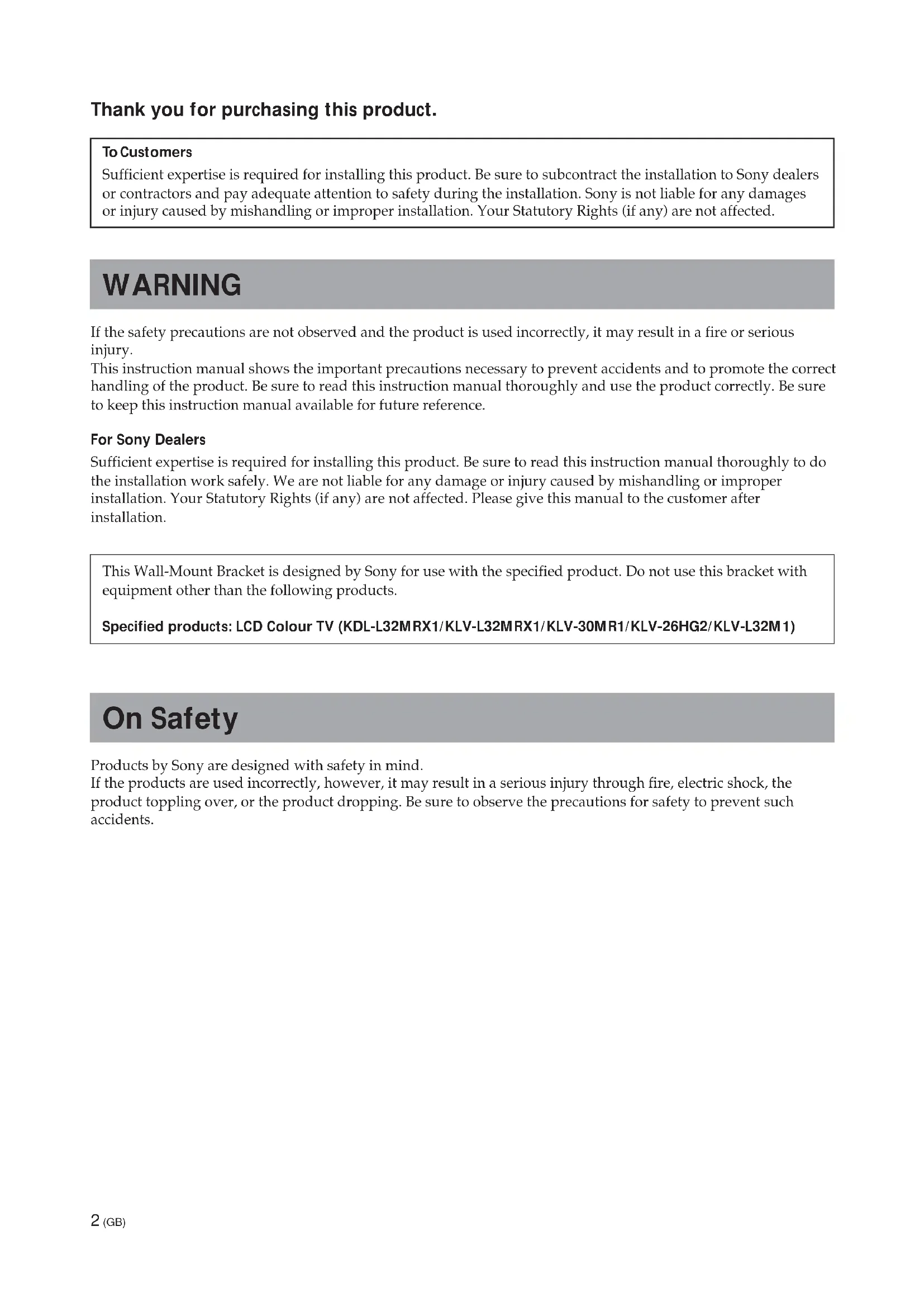
- The Display Unit may fall and cause a serious injury such as a bruise or a fracture during an earthquake.
- If the wall on which the Wall-Mount Bracket is installed is unstable, uneven, or not perpendicular to the floor, the unit may fall and cause injury or property damage. The wall should be capable of supporting a weight of at least four (4) times the Display Unit weight (KDL-L32MRX1/KLV-L32MRX1: 23 kg · 4 = 92 kg, KLV-30MR1: 20 kg · 4 = 80 kg, KLV-26HG2: 15 kg · 4 = 60 kg, KLV-L32M1: 17 kg · 4 = 68 kg).
- If the installation of the Wall-Mount Bracket on the wall is not sufficiently sturdy, the unit may fall and cause injury or property damage.
natural_image
Cartoon illustration of a person falling from a large screen with motion lines indicating shock (no text or symbols)Be sure to subcontract the installation to qualified contractors when moving or dismounting the Wall-Mount Bracket.
If persons other than qualified contractors transport or dismount the Wall-Mount Bracket, the Display Unit may fall and cause injury or property damage. Be sure that two or more persons carry or dismount the Wall-Mount Bracket.
Do not spill liquid of any kind on the Display Unit.
If you allow the Display Unit to get wet, this may result in a fire or an electric shock.
Do not remove bolts, etc., after mounting the Display Unit.
If you do so, the Display Unit may fall.
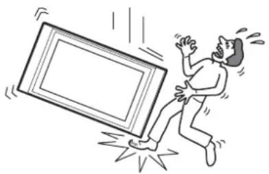
Do not disassemble or make alterations to the parts of the Wall-Mount Bracket.
If you do so, the Wall-Mount Bracket may fall and cause injury or property damage.
natural_image
Illustration of a person using a power tool to install electronic components (no text or symbols visible)Do not mount any equipment other than the specified product.
This Wall-Mount Bracket is designed for use with the specified product. If you mount equipment other than the specified product, it may fall and cause injury or property damage.
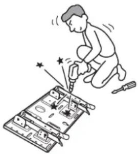
Do not block the ventilating holes on the Display Unit.
If you block the ventilating holes on the Display Unit by covering the top of the Display Unit with a cloth or the like, the Display Unit may become overheated and this may cause a fire.
natural_image
Simple line drawing of a steaming container with lid and handle (no text or symbols)Do not apply any load other than the Display Unit on the Wall-Mount Bracket.
If you do so, the Display Unit may fall and cause injury or property damage.
natural_image
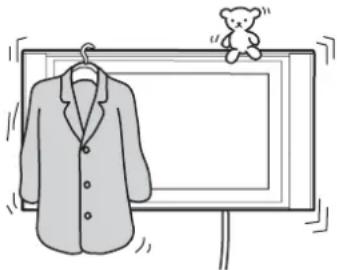
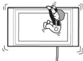
Simple line drawing of a jacket hanging on a hanger next to a blank display board with a teddy bear (no text or symbols)Do not lean on or hang from the Display Unit.
The Display Unit may fall and the user may be caught under the weight of the unit and suffer serious injury.
natural_image
Cartoon illustration of a person sitting on a TV screen with motion lines indicating speed (no text or symbols)To prevent a fire or an electric shock, do not expose the Display Unit to rain or moisture.
If you allow the Display Unit to get wet, this may result in a fire or an electric shock.
Never place the Display Unit in hot, humid or excessively dusty places. Do not install the Display Unit where it may be exposed to mechanical vibrations.
If you do so, this may cause a fire or an electric shock.
Keep flammable objects or open flames (e.g. candles) away from the Display Unit.
To prevent a fire, keep flammable objects or open flames (e.g. candles) away from the Display Unit.
CAUTION
If the following precautions are not observed, there is a possibility of injury or property damage.
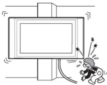
Do not install the Wall-Mount Bracket on wall surfaces where the corners or the sides of Display Unit would protrude away from the wall surface.
Do not install the Wall-Mount Bracket on wall surfaces such as a pillar, where the corners or the sides of Display Unit would protrude away from the wall surface. If a person or object happens to hit the protruded corner or side of the Display Unit, this may cause injury or property damage.
natural_image
Cartoon illustration of a person reacting with fireworks to a large screen (no text or symbols)Do not handle the product with excessive force during cleaning or maintenance.
Do not apply excessive force on the topside of the Display Unit.
If you do so, this may cause injury or property damage by causing the Display Unit to fall.
Do not install the Display Unit over or under an air-conditioner.
If you do so, the Display Unit may be exposed to air currents from the air-conditioner. This may result in a malfunction of the Display Unit.
Precautions
- If you use the Display Unit installed on the Wall-Mount Bracket for a long time, the wall behind or above the Display Unit may become discolored or the wallpaper may come unstuck, depending on the material of the wall. If the Wall-Mount Bracket is removed after installing them on the wall, the screw holes are left.
- If you have routed 300 ohm feeder cables behind the wall, we recommend that you change them to 75 ohm coaxial cables.
If it is necessary to continue to use 300 ohm feeder cables, be sure to confirm that sufficient space is available between the Display Unit and the feeder cables behind the wall before starting the installation.
Consult your contractor on an appropriate installation location where the Display Unit suffers no radio noise before starting the installation.
WARNING To Customers
Sufficient expertise is required for installing this product. Be sure to subcontract the installation to Sony dealers or contractors and pay adequate attention to safety during the installation.
To Sony Dealers
The following instructions are for Sony Dealers only. Be sure to read the following safety precautions and pay adequate attention to safety during the installation, maintenance and checking of this product.
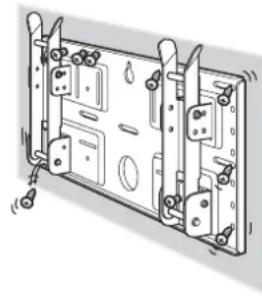
Be sure to install the Wall-Mount Bracket securely to the wall following the instructions in this instruction manual.
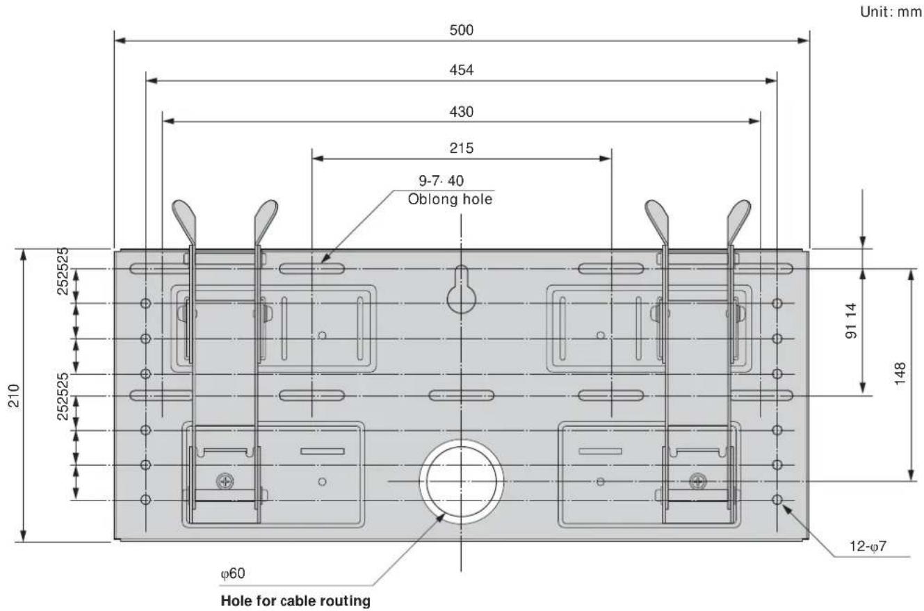
If any of the screws are loose or fall out, the Wall-Mount Bracket may fall and cause injury or property damage. Be sure to use the screws appropriate for the material of the wall and install the unit securely, using five or more M6 or the equivalent screws.
natural_image
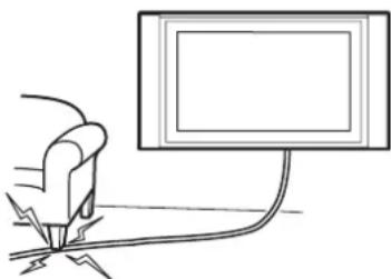
Technical line drawing of a mechanical assembly with mounting brackets and bolts (no text or symbols)Do not allow the Power Cord or the Display Cable to be pinched.
If the Power Cord or the Display Cable is pinched between the unit and the wall or is bent or twisted by force, the metallic part of the cord or cable may be exposed and cause a short circuit or a break in the cord or cable. This may cause a fire or an electric shock.
natural_image
Simple line drawing of a hand holding a tool near a computer monitor (no text or symbols)Be sure to use the supplied screws and attachment parts properly following the instructions given in this instruction manual. If you use substitute items, the Display Unit may fall, and cause bodily injury to someone or damage to the Display Unit.
Be sure to assemble the bracket properly following the instructed procedure explained in this instruction manual.
If any of the screws are loose or fall out, the Display Unit may fall, and cause bodily injury to someone or damage to the Display Unit.
Be sure to tighten the bolts and screws securely in the designated position.
If you fail to do so, the Display Unit may fall, and cause bodily injury to someone or damage to the Display Unit.
Be careful not to subject the Display Unit to shock during installation.
If the Display Unit is exposed to shock, it may fall or break apart. This may cause injury.
Be sure to install the Display Unit on a wall that is both perpendicular and flat.
If you fail to do so, the Display Unit may fall and cause injury.
After proper installation of the Display Unit, secure the cables properly.
If people or objects get tangled in the cables, this may result in injury.
Be careful not to hurt your hands or fingers during the installation.
Be careful not to hurt your hands or fingers when installing the Wall-Mount Bracket or the Display Unit.
The screws needed to secure the Wall-Mount Bracket to the wall are not supplied.
Use the appropriate screws for the wall material and structure when mounting the Wall-Mount Bracket.
Step 1: Check to see that you have all the items necessary for installation
1
Prepare five or more M6 or equivalent screws (not supplied) and a screwdriver. Select screws suitable for the material of the wall.
2
natural_image
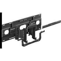
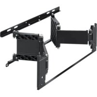
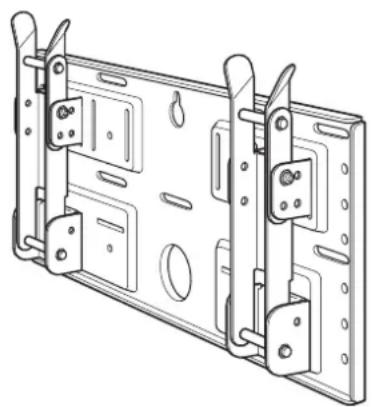
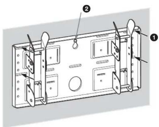
Technical line drawing of a mechanical assembly with mounting brackets and mounting holes (no text or symbols)Plate Unit (1) Mounting Hook Unit (2)
Unpack the carton and check to see that all the following items are included.
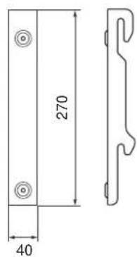
natural_image
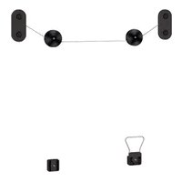
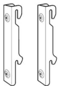
Two identical metal bracket components with mounting holes and notches, shown side by side (no text or symbols)
Screws (+B5 · L12) (2)

Screws (+PSW5 · L16) (4)
(For the KLV-26HG2)
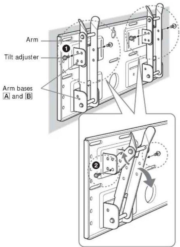
Step 2: Adjust the position of the arm bases (For the KLV-26HG2 and the KLV-L32M1 only)
1
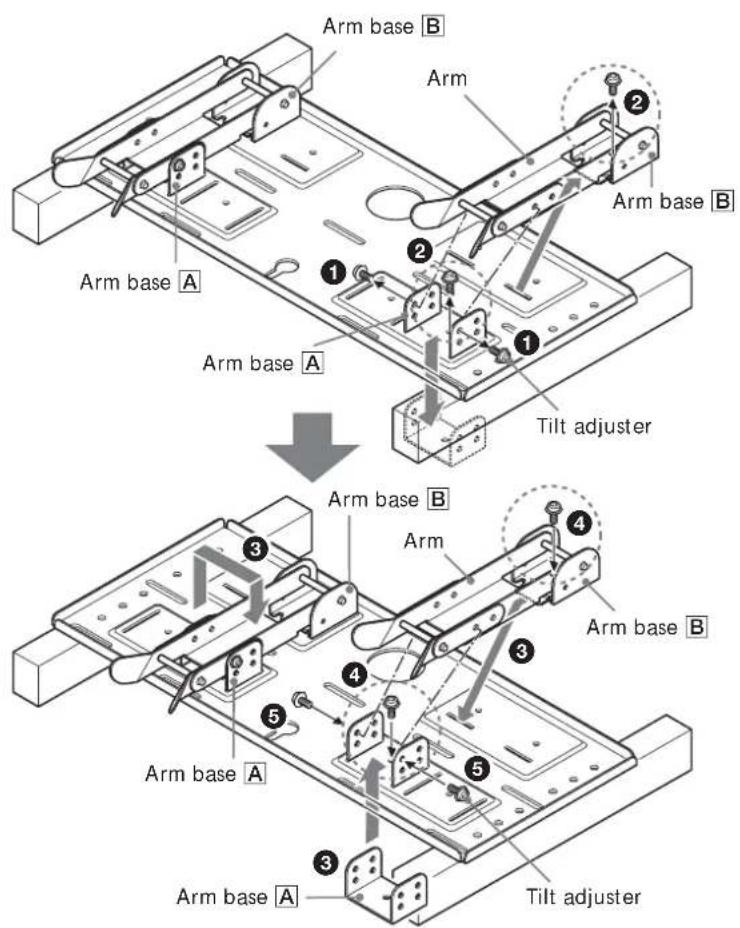
If you are going to install a KDL-L32MRX1, a KLV-L32MRX1 or a KLV-30MR1, skip Step 2 and go to Step 3.
① Remove the four (two for each arm bases) tilt adjusters.
② Remove the four screws that secure the arm bases to the Plate Unit.
③ Remove the arm bases A and put them in the slots facing inward. Put both arms and the arm bases B on the arm bases A.
④ Secure the arm bases to the Plate Unit using the four screws removed in ②.
⑤Secure the arms to the arm bases using the four tilt adjusters removed in ①.
Notes
- If you are installing a display other than the KLV-26HG2 or the KLV-L32M1, skip Step 2.
- When using an electric screwdriver to tighten the screws, the torque must be approx. 2 N·m.
Step 3: Decide on the location for installation
1
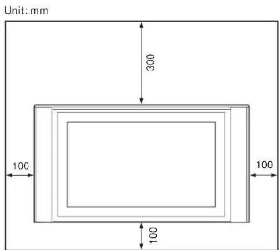
Leave spaces around the display. At least the amount of space shown in the diagram should be left between the display and a ceiling or raised portions of the wall.
Tip
Refer to the table (9 (GB)) for the display installation dimensions.
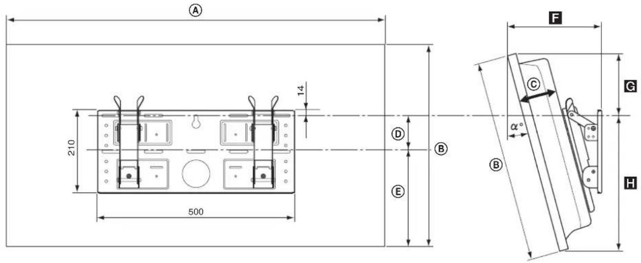
| Display Model | Display Dimensions Unit: mm | Length for each mounting angle Unit: mm | Weight (·4)* | |||||||
| A B C D E | Mounting angle ( ^ ) | F | G | H | ||||||
| KLV-30MR1 | 971 524 93 | 68 268 10° 206 167 352 | 0° 147 188 | 336 | 20 kg (80 kg) | |||||
| 5° 177 179 | 345 | |||||||||
| 15° 234 152 | 258 | |||||||||
| 20° 260 135 | 363 | |||||||||
| KDL-L32MRX1 | 1,052 | 569 97 | 31 291 10° | 219 225 339 | 0° 151 247 | 322 | 23 kg (92 kg) | |||
| 5° 186 237 | 331 | |||||||||
| 15° 252 209 | 345 | |||||||||
| 20° 282 190 | 350 | |||||||||
| KLV-L32MRX1 | 0° 167 150 | 280 | 15 kg (60 kg) | |||||||
| 5° 194 139 | 291 | |||||||||
| 15° 244 122 | 310 | |||||||||
| 20° 266 113 | 318 | |||||||||
| KLV-26HG2 | 790 430 118 | 65 215 10° | 220 129 301 | 0° 165 281 | 323 | 17 kg (68 kg) | ||||
| 5° 198 273 | 333 | |||||||||
| 10° | 230 | 262 | 342 | |||||||
| 15° 262 248 | 349 | |||||||||
| 20° 292 231 | 356 | |||||||||
* The wall must be strong enough to support at least four times the weight of the display that you are installing.
Refer to the diagram above for wall installation requirements (when reinforcing the wall or routing cables in the wall).
WARNING
The wall must be strong enough to support at least four times the weight of the display that you are installing (9 (GB)). Make sure the wall has sufficient strength. Reinforce the wall if necessary.
Step 4: Install the Plate Unit on the wall
1
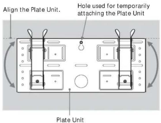
Temporarily secure the Plate Unit to the wall using a screw. Align the Plate Unit to make it level with the floor.
WARNING
- The screw used in this procedure is not supplied with the unit.
- Select a screw suitable for the material and the structure of the wall.
2
Secure the Plate Unit to the wall using four or more M6 or equivalent screws (not supplied).
① Tighten the screws firmly so that the Plate Unit can support the weight of the display.
② Tighten the screw used in 1.
WARNING
The wall must be strong enough to support at least four times the weight of the display that you installing (9 (GB)). Make sure the wall has sufficient strength. Reinforce the wall if necessary.
3
Adjust the tilt of the arms.
If you want to install the display vertically, flush with the wall (0°), skip ① and ② below. Check that the arms are securely attached to the Plate Unit.
①Remove all four tilt adjusters.
②Put them into the screw holes corresponding to the desired angle (5°, 10°, 15°, or 20°) and tighten them firmly.
Notes
- The angle of the left and right arms must be the same.
- Be careful not to catch your fingers when adjusting the angle of the arms.
- W hen using an electric screwdriver to tighten the screws, the torque must be approx. 2 N·m.
- Check that the arm bases are securely attached to the Plate Unit.
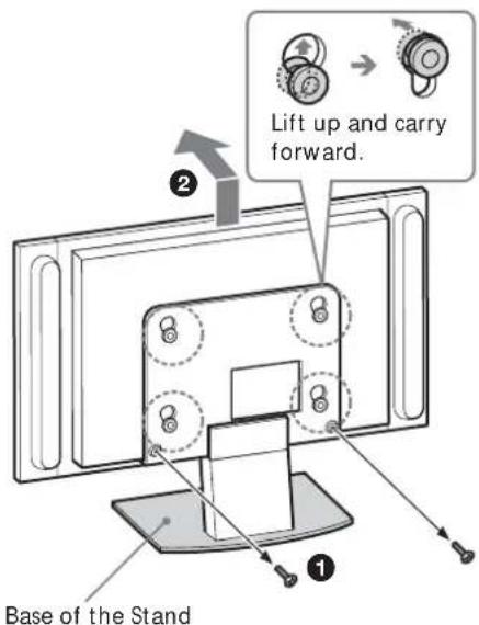
Step 5: Detach the display from the Tabletop Stand
The procedure differs depending on the display model. Apply the procedure appropriate for the display you are installing.
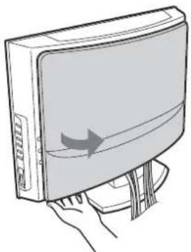
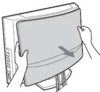
KLV-26HG2
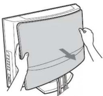
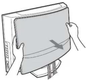
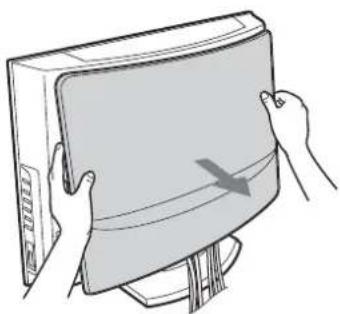
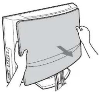
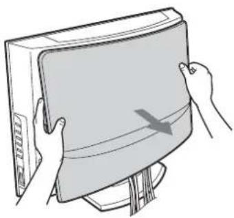
① Pull the lower corner (either right or left) of the rear cover. Then pull the other lower corner.
②Hold the rear cover with both hands and pull it towards you. The rear cover will separate from the display.
Note
Lay the display face down on a soft cloth before going to ③.
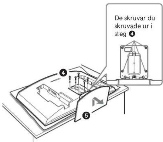
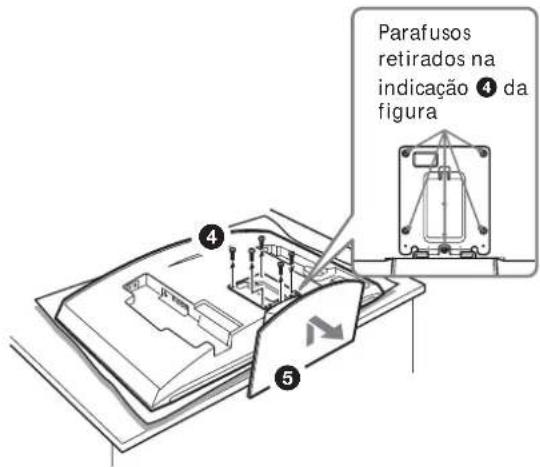
③ Remove the two small screws from the clip. Detach the clip from the Tabletop Stand.
4 Remove the five screws from the Tabletop Stand.
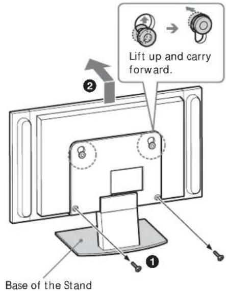
⑤ Lift up the Stand slightly, then pull it towards you. The Stand will separate from the display.
Notes
- Lay the display face down on a stable and level surface, leaving the base of the Stand sticking out in the air. Putting the display face and the base of the Stand on the same level surface makes the Display Unit inclined, thus unstable, causing any danger.
- When removing the Tabletop Stand, hold it firmly.
1
natural_image
Illustration of a hand holding a computer monitor with an arrow indicating direction (no text or symbols present)2
natural_image
Illustration of hands holding a computer monitor with a scroll wheel (no text or symbols)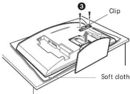
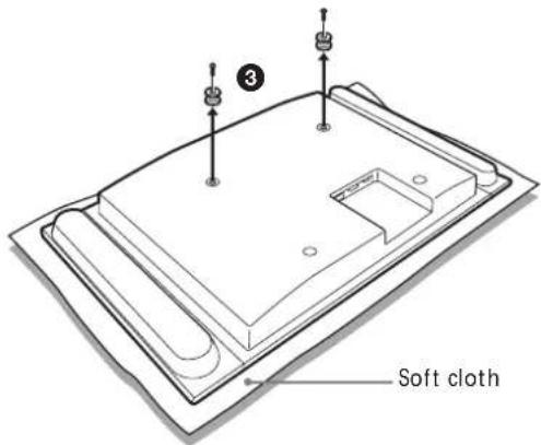
KLV-30MR1
①Remove the two screws from the Tabletop Stand.
Note
Do not lay the display down when carrying out the procedure.
② Holding down the base of the Stand, lift up the display slightly, then move it away from the Stand. The display will separate from the Stand. At least two persons must hold and carry the display.
Notes
- At least two persons must work together on this procedure.
- When lifting up the display, hold the base of the Stand so that it is not lifted along with the display.
③ Remove the four hooks on the rear cover of the display.
Note
Lay the display face down on a soft cloth.
KDL-L32MRX1 KLV-L32MRX1
①Remove the two screws from the Tabletop Stand.
Note
Do not lay the display down when carrying out the procedure.
② Holding down the base of the Stand, lift up the display slightly, then move it away from the Stand. The display will separate from the Stand. At least two persons must hold and carry the display.
Notes
- At least two persons must work together on this procedure.
- When lifting up the display, hold the base of the Stand so that it is not lifted along with the display.
③ Remove the two hooks on the rear cover of the display.
Note
Lay the display face down on a soft cloth.
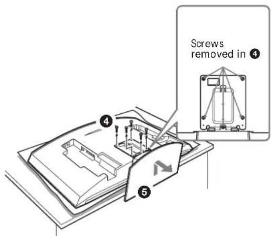
KLV-L32M1
Note
Lay the display face down on a soft cloth before going to 1.
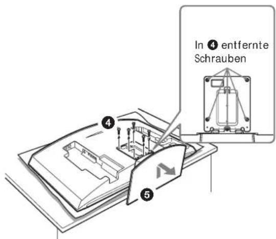
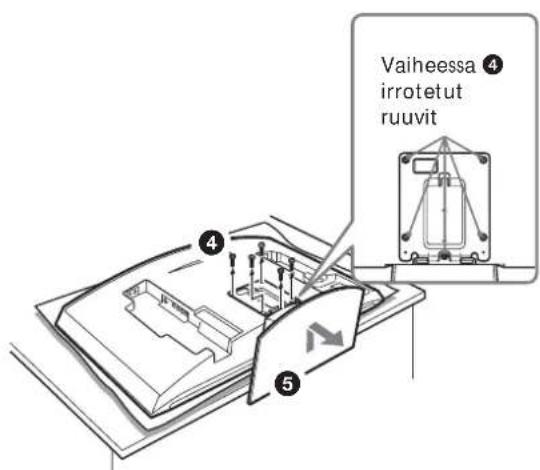
① Remove the four screws from the rear cover of the display.
② Pull the stand towards you. The Stand will separate from the display.
③ Remove the four screws on the rear cover of the display.
Notes
- Lay the display face down on a stable and level surface, leaving the base of the Stand sticking out in the air.
Putting the display face and the base of the Stand on the same level surface makes the Display Unit inclined, thus unstable, causing any danger. - When removing the Tabletop Stand, hold it firmly.
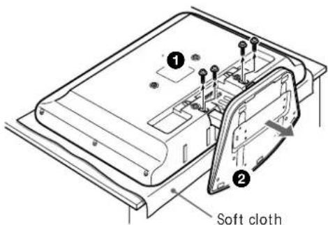
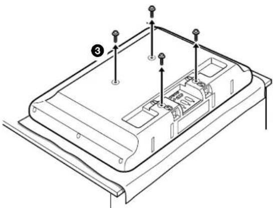
natural_image
Technical line drawing of a device casing with mounting holes and internal compartments (no text or symbols)Step 6: Install the display on the Plate Unit
WARNING
Do not connect the power cord to a wall socket before the installation is completed. If the mains lead is pinched, a short circuit may occur, causing an electric shock.
Be careful not to stumble over the cables or the display.
1
KLV-26HG2

KDL-L32MRX1/KLV-L32MRX1/KLV-30MR1
KLV-L32M1
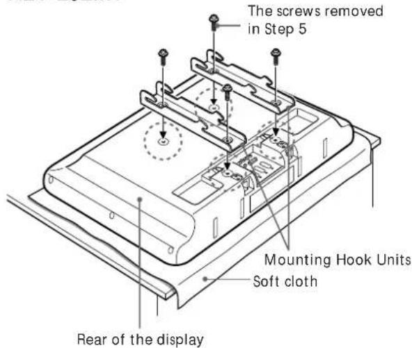
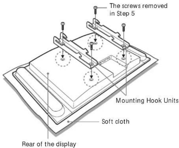
Align the holes on the Mounting Hook Units with the corresponding holes on the rear of the display. Secure them to the display using four screws.
For the KLV-26HG2, use the screws supplied (+PSW5·L16). For the KDL-L32MRX1, the KLV-L32MRX1, the KLV-30MR1, and the KLV-L32M1 use the screws you removed in Step 5.
Notes
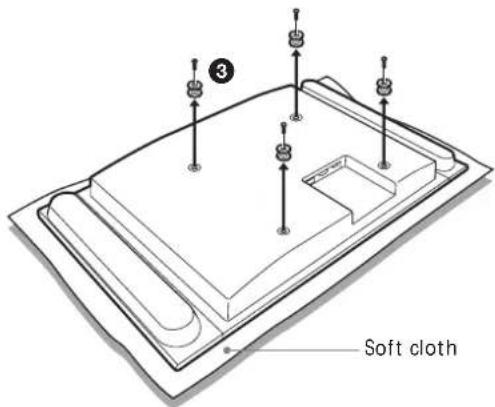
- Lay the display face down on a soft cloth.
- When using an electric screwdriver to tighten the screws, the torque must be approx. 2 N·m.
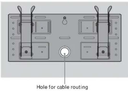
Connect the supplied mains lead and cables.
Connect the mains lead and cables to the corresponding jacks on the rear of the display. For details on the cable connection, see the Operating Instructions for your display.
When routing cables in a wall, pass the cables through a hole made in the wall for cable routing (10 (GB)).
Notes
- You cannot connect the cables to the display after installing it on the Plate Unit.
- Subcontract the cable routing in the wall to qualified contractors.
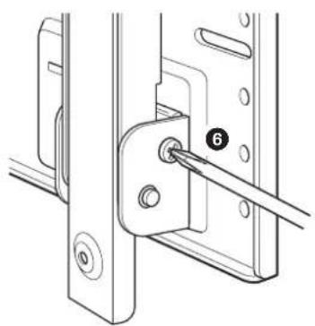
3

natural_image
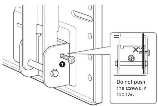
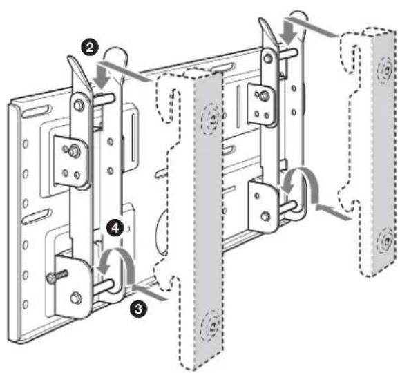
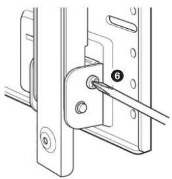
Technical line drawing of a mechanical assembly with a pin inserted into a bracket (no text or symbols)Mount the display on the Plate Unit.
To lock the arms temporarily, put the two securing screws (+B5 · L12, supplied) in the holes on the arm bases B from the outside.
② Hang the upper hooks of the Mounting Hook Units on the upper shafts of the arms.
③ Place the lower hooks of the Mounting Hook Units on the lower shafts of the arms.
4 Pushing the display towards the Plate Unit, lift it up slowly and hang the lower hooks of the arms onto the lower shafts.
⑤ Check to make sure that all eight hooks are properly hung on the corresponding shafts.
⑥ Tighten the securing screws attached in ①.
Note
If you push the securing screws into the holes too far (1), the tips of the screws will get in the way when you hang the lower hooks on the shafts (4).
Check to make sure all the procedures have been properly completed
Check the following.
- All eight hooks are securely hung on the corresponding shafts.
- The cables are neither twisted nor pinched.
- The two securing screws are securely tightened.
WARNING
If not properly installed, the unit may fall, causing injury to persons or damage to the unit itself. If the cables are not properly routed, a short circuit may occur, causing a fire or an electric shock. For your safety, be sure to check that all the procedures have been properly carried out.
To dismount the display
For Sony Dealers
1
Unplug the mains lead from the wall socket.
2
Remove the two securing screws.
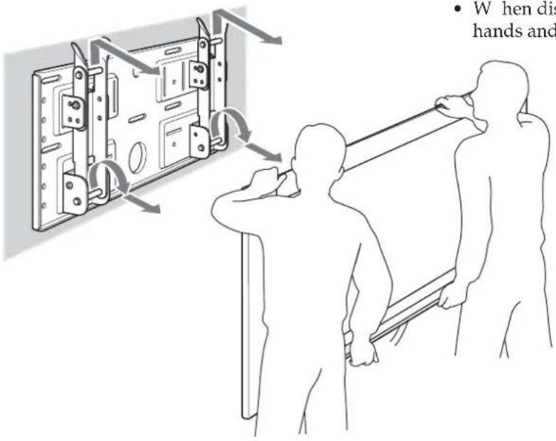
3
Two or more persons should lift up the display and dismount it from the Plate Unit.
WARNING
- At least two persons must hold and carry the display.
- When dismounting the display, be careful not to catch the cables.
- When dismounting the display, be careful of your hands and fingers.
Specifications
Unit: mm
Mass: 3.4 kg


Design and specifications are subject to change without notice.
natural_image
Cartoon illustration of a person falling from a large screen to the ground, with no text or symbols present.natural_image
Illustration of a person using a power tool to install electronic components (no text or symbols visible)natural_image
Simple line drawing of a steaming container with lid and side panel (no text or symbols)natural_image
Illustration of a jacket hanging on a hanger next to a blank display board with a teddy bear (no text or symbols)natural_image
Cartoon illustration of a child peeking from behind a TV screen (no text or symbols)natural_image
Cartoon illustration of a person reacting to a wall-mounted screen with stars, no text or symbols presentnatural_image
Technical line drawing of a mechanical assembly with mounting brackets and bolts (no text or symbols)natural_image
Simple line drawing of a hand holding a tool near a computer monitor (no text or symbols)natural_image
Technical line drawing of a metal enclosure frame with mounting brackets and mounting holes (no text or symbols)Plaque de fixation (1) Crochet de fixation (2)
natural_image
Two identical line drawings of metal bracket components with mounting holes (no text or symbols)
Vis (+B5 · L12) (2)

Vis (+PSW5 · L16) (4)
(Pour le KLV-26HG2)
natural_image
Technical diagram of a dual-chamber electrical enclosure with rotating components and wiring (no text or labels)Plaque de fixation
natural_image
Line drawing of a hand pressing a cable to a computer monitor (no text or symbols)2
natural_image
Illustration of hands holding a rectangular object with a curved arrow indicating motion or force (no text or symbols)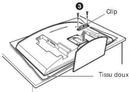

natural_image
Technical line drawing of a device casing with mounting holes and internal compartments (no text or symbols)
natural_image
Technical line drawing of a mechanical bracket with a pin inserted, showing no text or symbolsnatural_image
Cartoon illustration of a person falling from a large screen with a distressed expression (no text or symbols)natural_image
Illustration of a person using a screwdriver to adjust or install a mechanical component (no text or symbols present)natural_image
Simple line drawing of a steaming container with steam rising (no text or symbols)natural_image
Illustration of a jacket hanging on a wall next to a blank board, with a teddy bear resting nearby (no text or symbols)natural_image
Cartoon illustration of a child peeking from behind a TV screen (no text or symbols)natural_image
Cartoon illustration of a person reacting to a wall-mounted screen with stars, no text or symbols presentnatural_image
Technical line drawing of a mechanical assembly with mounting brackets and bolts (no text or symbols)natural_image
Simple line drawing of a computer monitor connected to a cable with a lightning bolt (no text or symbols)natural_image
Technical line drawing of a mechanical assembly with mounting brackets and internal components (no text or symbols)natural_image
Illustration of a hand holding a computer monitor with a curved screen and scroll, no text or symbols present2
natural_image
Illustration of hands holding a rectangular object with a curved arrow indicating motion (no text or symbols)

natural_image
Technical diagram of a mechanical assembly with a numbered component (6) and no visible text or symbolsnatural_image
Cartoon illustration of a person falling from a large screen with a distressed expression (no text or symbols)natural_image
Illustration of a person using a screwdriver to install electronic components (no text or symbols visible)natural_image
Simple line drawing of a steaming container with lid and handle (no text or symbols)natural_image
Simple line drawing of a jacket hanging on a hanger next to a blank display board with a teddy bear (no text or symbols)natural_image
Cartoon illustration of a child peeking from behind a TV screen (no text or symbols)natural_image
Cartoon illustration of a person running away from a monitor with stars and sparkles, no text or symbols presentnatural_image
Technical line drawing of a mechanical assembly with mounting brackets and bolts (no text or symbols)natural_image
Simple line drawing of a hand holding a computer monitor connected to a cable (no text or symbols)natural_image
Technical line drawing of a metal enclosure frame with mounting brackets and mounting holes (no text or symbols)natural_image
Two identical line drawings of metal bracket components with mounting holes (no text or symbols)
Tornillos (+B5 · L12) (2)

Tornillos (+PSW5 · L16) (4)
(Para KLV-26HG2)
natural_image
Line drawing of a hand pressing a CD-ROM with an arrow indicating compression (no text or symbols)2
natural_image
Illustration of hands holding a closed book with a curved arrow indicating motion (no text or symbols)

natural_image
Technical line drawing of a mechanical assembly with a pin inserted into a bracket (no text or symbols)natural_image
Cartoon illustration of a person falling from a large screen with a distressed expression (no text or symbols)natural_image
Illustration of a person using a power tool to install electronic components (no text or symbols visible)natural_image
Simple line drawing of a steaming container with lid and handle (no text or symbols)natural_image
Simple line drawing of a jacket hanging on a hanger next to a blank display board with a teddy bear (no text or symbols)natural_image
Cartoon illustration of a person sitting on a TV screen with motion lines indicating speed (no text or symbols)natural_image
Cartoon illustration of a person in a hard hat reacting to a wall-mounted device with stars, no text or symbols presentnatural_image
Technical line drawing of a mechanical assembly with mounting brackets and bolts (no text or symbols)natural_image
Simple line drawing of a computer monitor connected to a cable with a lightning bolt (no text or symbols)natural_image
Technical line drawing of a mechanical assembly with mounting brackets and mounting holes (no text or symbols)Plaat (1)
natural_image
Two identical line drawings of metal bracket components with mounting holes (no text or symbols)Montageklemmen (2)

Schroeven
(+B5 · L12) (2)

Schroeven (+PSW5 · L16) (4)
(Voor de KLV-26HG2)
natural_image
Illustration of a hand pressing a curved monitor with an arrow symbol (no text or labels)2
natural_image
Illustration of hands holding a closed book with a curved cover and arrow indicating motion (no text or symbols)


natural_image
Technical line drawing of a mechanical bracket with a pin inserted, showing no text or symbolsnatural_image
Cartoon illustration of a person falling from a large screen with a distressed expression (no text or symbols)natural_image
Illustration of a person using a screwdriver to install electronic components (no text or symbols visible)natural_image
Simple line drawing of a steaming container with lid and handle (no text or symbols)natural_image
Simple line drawing of a jacket hanging on a hanger next to a blank display board with a teddy bear (no text or symbols)natural_image
Cartoon illustration of a child watching a picture on a flat-screen TV (no text or symbols)natural_image
Cartoon illustration of a person reacting with fireworks to a large screen (no text or symbols)natural_image
Technical line drawing of a mechanical assembly with mounting brackets and bolts (no text or symbols)natural_image
Simple line drawing of a hand holding a tool near a computer monitor (no text or symbols)natural_image
Technical line drawing of a mechanical assembly with mounting brackets and mounting holes (no text or symbols)Monteringsplatta (1) Monteringskrokar (2)
natural_image
Two identical line drawings of metal bracket components with mounting holes (no text or symbols)
Skruvar (+B5 · L12) (2)
natural_image
Illustration of a hand pressing a CD-ROM with a scroll arrow (no text or symbols)2

natural_image
Illustration of hands holding a closed book with a curved arrow indicating motion (no text or symbols)
KLV-30MR1
Steg 6: Montera skärmen på monteringsplattan
WARNING!
natural_image
Technical line drawing of a mechanical assembly with a pin inserted into a bracket (no text or symbols)Montera skärmen på monteringsplattan.
natural_image
Cartoon illustration of a person falling from a large screen with a distressed expression (no text or symbols)natural_image
Illustration of a person using a screwdriver to install electronic components (no text or symbols visible)natural_image
Simple line drawing of a steaming container with lid and handle (no text or symbols)natural_image
Simple line drawing of a jacket hanging on a hanger next to a blank display board with a teddy bear (no text or symbols)natural_image
Cartoon illustration of a child watching a picture on a flat-screen TV (no text or symbols)natural_image
Cartoon illustration of a person reacting with fireworks to a large screen (no text or symbols)natural_image
Technical line drawing of a mechanical assembly with mounting brackets and bolts (no text or symbols)natural_image
Simple line drawing of a hand inserting a cable into a monitor (no text or symbols)natural_image
Technical line drawing of a mechanical assembly with mounting brackets and mounting holes (no text or symbols)natural_image
Two identical line drawings of metal bracket components with mounting holes (no text or symbols)natural_image
Illustration of a hand pressing a button on a computer monitor (no text or symbols visible)2
natural_image
Illustration of hands holding a computer monitor with a scroll, no text or symbols present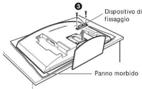
natural_image
Technical line drawing of a device casing with mounting holes and internal compartments (no text or symbols)natural_image
Top-down schematic of a dual-chamber electronic device with two ports and a central knob (no text or symbols)
natural_image
Technical line drawing of a mechanical assembly with a pin inserted into a bracket (no text or symbols)natural_image
Illustration of two people installing or adjusting a wall-mounted device, with no visible text or symbols.natural_image
Cartoon illustration of a person falling from a large screen to the ground, with no text or symbols present.natural_image
Illustration of a person using a screwdriver to adjust or install electronic components (no text or symbols visible)natural_image
Simple line drawing of a steaming container with lid and handle (no text or symbols)natural_image
Illustration of a jacket hanging on a screen with a teddy bear nearby (no text or symbols)natural_image
Cartoon illustration of a person sitting on a TV screen with a bird flying nearby (no text or symbols)natural_image
Cartoon illustration of a person reacting with fireworks to a large screen (no text or symbols)natural_image
Technical line drawing of a mechanical housing or enclosure with mounting holes and internal components (no text or symbols)natural_image
Simple line drawing of a hand holding a cable with a computer monitor on top (no text or symbols)natural_image
Technical line drawing of a mechanical assembly with mounting brackets and mounting holes (no text or symbols)Placa (1)
natural_image
Two identical line drawings of metal bracket components with mounting holes (no text or symbols)natural_image
Illustration of a hand pressing a computer monitor with a curved screen and scroll (no text or symbols)2

natural_image
Illustration of hands holding a computer monitor with a scroll, no text or symbols present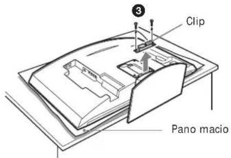
natural_image
Technical line drawing of a device casing with mounting holes and internal compartments (no text or symbols)natural_image
Top-down schematic of a dual-chamber electronic device with two ports and a central knob (no text or symbols)
natural_image
Technical diagram of a mechanical assembly with a numbered component (6) and no visible text or symbolsnatural_image
Cartoon illustration of a person falling from a large screen to the ground, with no text or symbols present.natural_image
Illustration of a person using a screwdriver to install electronic components (no text or symbols visible)natural_image
Simple line drawing of a rectangular container with a lid and steam rising above it (no text or symbols)natural_image
Illustration of a coat hanging on a hanger next to a blank display board with a teddy bear (no text or symbols)natural_image
Cartoon illustration of a child peeking from behind a TV screen (no text or symbols)natural_image
Cartoon illustration of a person reacting to a large screen with stars, no text or symbols presentnatural_image
Technical line drawing of a mechanical assembly with mounting brackets and bolts (no text or symbols)natural_image
Simple line drawing of a hand holding a computer monitor connected to a cable (no text or symbols)natural_image
Technical line drawing of a mechanical assembly with mounting brackets and mounting holes (no text or symbols)natural_image
Two identical line drawings of metal bracket components with mounting holes (no text or symbols)natural_image
Illustration of a hand pressing a computer monitor with a curved arrow on the screen (no text or symbols)2
natural_image
Illustration of hands holding a computer monitor with a scroll, no text or symbols present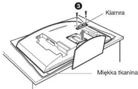

natural_image
Technical line drawing of a mechanical assembly with a pin inserted into a bracket (no text or symbols)natural_image
Cartoon illustration of a person falling from a large screen with a distressed expression (no text or symbols)natural_image
Illustration of a person using a screwdriver to adjust or install electronic components (no text or symbols visible)natural_image
Simple line drawing of a steaming container with lid and handle (no text or symbols)natural_image
Illustration of a jacket hanging on a wall next to a teddy bear, with no text or symbols present.natural_image
Cartoon illustration of a person sitting on a TV screen with a smiling face (no text or symbols)natural_image
Cartoon illustration of a person running toward a large screen with stars, no text or symbols presentnatural_image
Technical line drawing of a mechanical assembly with mounting brackets and bolts (no text or symbols)natural_image
Simple line drawing of a computer monitor connected to a cable with a lightning bolt (no text or symbols)natural_image
Technical line drawing of a mechanical bracket assembly (no text or symbols)natural_image
Two identical line drawings of metal bracket components with mounting holes (no text or symbols)natural_image
Illustration of a hand pressing a computer monitor with an arrow indicating motion (no text or symbols present)
natural_image
Illustration of hands holding a computer monitor with a scroll, no text or symbols present
natural_image
Technical line drawing of a device casing with mounting holes and internal compartments (no text or symbols)natural_image
Diagram of a dual-panel electronic device with two ports and a central knob (no text or symbols)
natural_image
Technical line drawing of a mechanical assembly with a pin inserted into a bracket (no text or symbols)natural_image
Cartoon illustration of a person falling from a large screen with a distressed expression (no text or symbols)natural_image
Illustration of a person using a power tool to install electronic components (no text or symbols visible)natural_image
Simple line drawing of a steaming container with lid and handle (no text or symbols)natural_image
Simple line drawing of a jacket hanging on a hanger next to a blank display board with a teddy bear (no text or symbols)natural_image
Cartoon illustration of a child watching a picture on a flat-screen TV (no text or symbols)natural_image
Cartoon illustration of a person reacting with sparkles to hit a rectangular panel (no text or symbols)natural_image
Technical line drawing of a mechanical assembly with mounting brackets and internal components (no text or symbols)natural_image
Simple line drawing of a hand holding a tool near a computer monitor (no text or symbols)natural_image
Technical line drawing of a mechanical assembly with mounting brackets and internal components (no text or symbols)natural_image
Two identical line drawings of metal bracket components with mounting holes (no text or symbols)natural_image
Illustration of a hand pressing a cable to a computer monitor with an arrow indicating motion (no text or symbols)2
natural_image
Illustration of hands holding a computer monitor with a scroll, no text or symbols present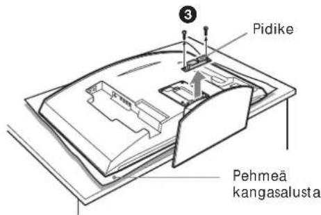
KLV-30MR1
natural_image
Diagram of a dual-panel electronic device with switches and a central knob (no text or symbols)
natural_image
Technical line drawing of a mechanical assembly with a pin inserted into a bracket (no text or symbols)natural_image
Line drawing of two people installing or adjusting a wall-mounted device, with no visible text or symbols.Tekniset tiedot
Mittayksikkö: mm
Paino: 3,4 kg

natural_image
Cartoon illustration of a person falling from a large screen to the ground, with no text or symbols present.natural_image
Illustration of a person using a screwdriver to install electronic components (no text or symbols visible)Monter kun det specificerede produkt.
natural_image
Simple line drawing of a steaming container with lid and handle (no text or symbols)natural_image
Illustration of a jacket hanging on a screen with a teddy bear nearby (no text or symbols)natural_image
Cartoon illustration of a person sitting on a TV with arms outstretched (no text or symbols)natural_image
Cartoon illustration of a person reacting with fireworks to a large screen (no text or symbols)natural_image
Technical line drawing of a mechanical assembly with mounting brackets and internal components (no text or symbols)natural_image
Simple line drawing of a hand holding a tool near a computer monitor (no text or symbols)natural_image
Technical line drawing of a mechanical assembly with mounting brackets and mounting holes (no text or symbols)Plade (1)
natural_image
Two identical line drawings of metal bracket components with mounting holes (no text or symbols)Monteringsenhed (2)

Skruer (+B5 · L12) (2)

Skruer (+PSW5 · L16) (4)
(til KLV-26HG2)
natural_image
Illustration of a hand pressing a cable with a curved arrow on the screen (no text or symbols)2

natural_image
Illustration of hands holding a computer monitor with a scroll, no text or symbols present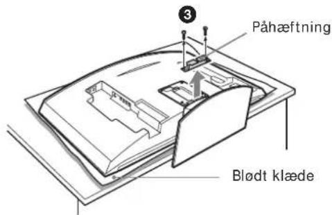
natural_image
Technical line drawing of a mechanical assembly with a pin inserted into a bracket (no text or symbols)natural_image
Illustration of two silhouetted figures installing or adjusting a wall-mounted device, with no visible text or symbols.Specifikationer
Enhed: mm
Vægt: 3,4 kg
natural_image
Cartoon illustration of a person falling from a large screen with a distressed expression (no text or symbols)natural_image
Illustration of a person using a power tool to install components on a device (no text or symbols present)natural_image
Simple line drawing of a steaming container with lid and handle (no text or symbols)natural_image
Simple line drawing of a jacket hanging on a wall next to a blank display board with a teddy bear (no text or symbols)natural_image
Cartoon illustration of a child peeking from behind a TV screen (no text or symbols)natural_image
Cartoon illustration of a person reacting with fireworks to a large screen (no text or symbols)natural_image
Technical line drawing of a mechanical assembly with mounting brackets and bolts (no text or symbols)natural_image
Simple line drawing of a hand holding a tool near a computer monitor (no text or symbols)natural_image
Technical line drawing of a mechanical assembly with mounting brackets and internal components (no text or symbols)Plate (1) Monteringskrok (2)
natural_image
Two identical metal bracket components with mounting holes and notches, shown side by side (no text or symbols)
Skruer (+B5 · L12) (2)

Skruer (+PSW5 · L16) (4)
(for KLV-26HG2)
natural_image
Illustration of a hand pressing a cable with a curved arrow on the screen (no text or symbols)2
natural_image
Illustration of hands holding a closed book with a curved arrow indicating motion (no text or symbols)
KLV-30MR1

natural_image
Technical line drawing of a mechanical assembly with a pin inserted into a bracket (no text or symbols)Monter skjermen på platen.
Printed on 100% recycled paper using VOC (Volatile Organic Compound)-free vegetable oil based ink.