
SUWL830 - Wall mount SONY - Free user manual and instructions
Find the device manual for free SUWL830 SONY in PDF.
| Product type | Wall mount |
| Brand | Sony |
| Model | SUWL830 |
| Compatibility | Specified Sony TVs (refer to TV reference manual) |
| Supported wall types | Drywall with studs (max thickness 16 mm) and solid concrete/concrete block (min thickness 203 mm) |
| Dimensions (approx.) | 1040 mm (W) x 273 mm (H) x 245 mm (D) |
| Base weight (only) | WM5: 4.9 kg / WM1: 2.7 kg |
| Recommended load capacity | Wall must support at least 6 times the weight of the TV |
| Installation | Professional required (by certified installer) |
| Angle adjustment | Yes, via left/right screws of the mount |
| Lateral movement | Yes, for drywall with studs (lateral movement bracket included) |
| Screws provided | Lag bolts WS2, fixing screws, WA1 sleeves, etc. (depending on wall type) |
| Maintenance and cleaning | Clean with a soft cloth; do not apply excessive force |
| Safety instructions | Do not modify parts, do not hang other equipment, keep children away |
| Spare parts and repairability | Contact Sony customer service; do not use non-supplied parts |
| Warranty | Standard Sony (not specified in manual) |
Frequently Asked Questions - SUWL830 SONY
User questions about SUWL830 SONY
0 question about this device. Answer the ones you know or ask your own.
Ask a new question about this device
Download the instructions for your Wall mount in PDF format for free! Find your manual SUWL830 - SONY and take your electronic device back in hand. On this page are published all the documents necessary for the use of your device. SUWL830 by SONY.
USER MANUAL SUWL830 SONY
Thank you for purchasing this product.
To Customers
Installing the TV to the Wall

WARNING
PROFESSIONAL INSTALLATION REQUIRED
This product should only be installed by a professional installer who is trained to determine the strength of the wall for withstanding the TV's weight. If it is not properly secured during installation, the TV may fall and cause serious injury. Sony is not liable for any damage or injury caused by mishandling or improper installation, or installing any other than the specified product. Your Statutory Rights (if any) are not affected.
To Sony dealers
Sufficient expertise is required for installing this product. Be sure to read this instruction manual thoroughly to do the installation work safely. Sony is not liable for any damages or injury caused by mishandling or improper installation. Please give this manual to the customer after installation.
This instruction manual shows the correct handling of the product and important precautions necessary to prevent accidents. It is your responsibility to read, thoroughly understand, and follow all instructions in this instruction manual. Failure to do so may result in serious personal injury or property damage, and may void the warranty. Keep this manual available for future reference.
Products by Sony are designed with safety in mind. If the products are used incorrectly, however, it may result in a serious injury through fire, electric shock, the product toppling over, or the product dropping. Be sure to observe the precautions for safety to prevent such accidents.
CAUTION
Specified products
This Wall-Mount Bracket is designed for use with the products specified TVs. For TVs, refer to their "Reference Guide" to verify that the Wall-Mount Bracket can be used.
To Customers
WARNING
If the following precautions are not observed, serious injury or death through fire, electric shock, or the product dropping can result.
Be sure to subcontract the installation to licensed contractors and keep small children away during the installation.
If the Wall-Mount Bracket or the TV is not installed correctly, the following accidents may occur. Be sure licensed contractors carry out installation.
- The TV may fall and cause a serious injury such as a bruise or a fracture.
- If the wall on which the Wall-Mount Bracket is installed is unstable, uneven, or not perpendicular to the floor, the unit may fall and cause injury or property damage. The wall should be capable of supporting a weight of at least six times the TV weight.
(Refer to your TV's "Reference Guide" for its weight.) - If the installation of the Wall-Mount Bracket on the wall is not sufficiently sturdy, the unit may fall and cause injury or property damage.
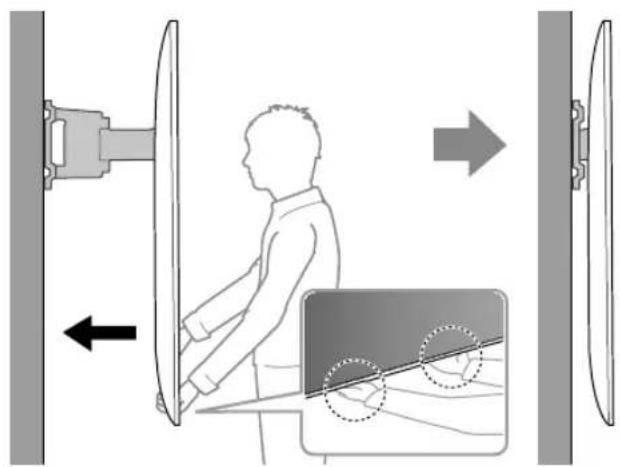
Be sure to subcontract moving or dismounting of the TV to licensed contractors.
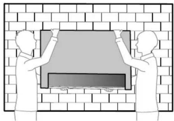
If persons other than licensed contractors transport or dismount the TV, it may fall and cause injury or property damage. Be sure that two or more persons carry or dismount the TV.
Do not remove screws, etc., after mounting the TV.
If you do so, the TV may fall and cause injury or property damage.
Do not make alterations to the parts of the Wall-Mount Bracket.
If you do so, the Wall-Mount Bracket may fall and cause injury or property damage.
Do not mount any equipment other than the specified product.
This Wall-Mount Bracket is designed for use with the specified product only. If you mount equipment other than specified, it may fall or break, and cause injury or property damage.
Do not apply any load other than the TV on the Wall-Mount Bracket. Do not shake the TV left/right, up/down.
If you do so, the TV may fall and cause injury or property damage.
Do not lean on or hang from the TV.
Do not lean on or hang from the TV as it may fall on you and cause serious injury.
CAUTION
If the following precautions are not observed, injury or property damage may occur.
- Be careful to not pinch your fingers while handling the Wall-Mount Bracket or swiveling the TV set.
- While swiveling the TV set, handle it with caution and take care not to hit any people nearby.
- Be sure to store the unused parts in a safe place for future use.
Keep them away from children.
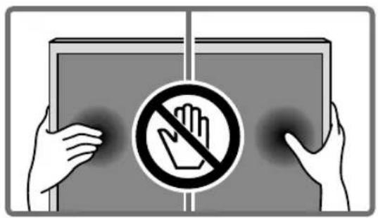
Do not handle the product with excessive force during cleaning or maintenance.
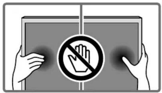
Do not apply excessive force on the topside of the TV. If you do so, the TV may fall and cause injury or property damage.
Precautions
- If you use the TV installed on the Wall-Mount Bracket for a long time, the wall behind or above the TV may become discolored or the wallpaper may come unstuck, depending on the material of the wall.
- If the Wall-Mount Bracket is removed after installing it on the wall, the screw holes are left.
- Do not use the Wall-Mount Bracket in a place where it is subjected to mechanical vibrations.
Installing the Wall-Mount Bracket
To Sony Dealers
WARNING
The following instructions are for Sony dealers only. Be sure to read safety precautions described above and pay special attention to safety during the installation, maintenance and checking of this product.
Do not install the Wall-Mount Bracket on wall surfaces where the corners or the sides of the TV protrude away from the wall surface.
Do not install the Wall-Mount Bracket on wall surfaces such as a pillar, where the corners or the sides of the TV protrude away from the wall surface. If a person or object happens to hit the protruded corner or side of the TV, it may cause injury or property damage.
Do not install the TV over or under an air-conditioner.
If the TV is exposed to water leaks or air current from an air conditioner for a long time, it may cause a fire, an electric shock or a malfunction of the TV.
Be sure to install the Wall-Mount Bracket securely to the wall following the instructions in this instruction manual.
If any of the screws are loose or fall out, the Wall-Mount Bracket may fall and cause injury or property damage. Be sure to use the appropriate screws for the material of the wall and install the unit securely, using supplied screw and anchors.
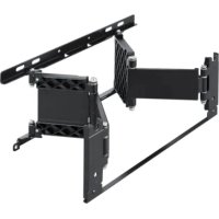
natural_image
Technical line drawing of a mechanical assembly with mounting holes and internal components (no text or symbols)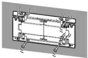
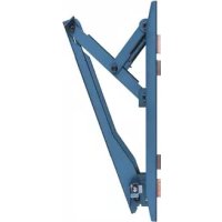
natural_image
Diagram of a battery pack with cooling fins and heat exchangers (no text or labels)Be sure to use the supplied screws and attachment parts properly following the instructions given in this instruction manual. If you use substitute items, the TV may fall and cause bodily injury to someone or damage to the TV.
Be sure to assemble the bracket properly following the instructed procedure explained in this instruction manual.
If any of the screws are loose or fall out, the TV may fall and cause bodily injury to someone or damage to the TV.
Be sure to tighten the screws securely in the designated position.
If you fail to do so, the TV may fall and cause bodily injury to someone or damage to the TV.
Be careful not to subject the TV to shock during installation.
If the TV is exposed to shock, it may fall or break apart. This may cause injury.
Be sure to install the TV on a wall that is both perpendicular and flat.
If you fail to do so, the TV may fall and cause injury.
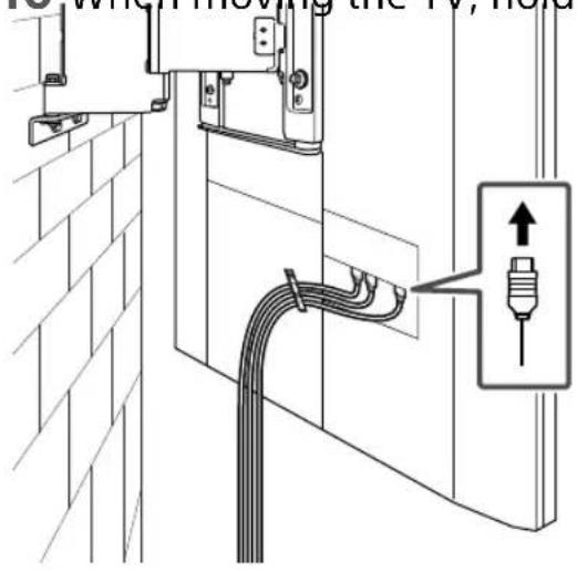
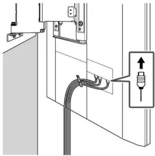
After proper installation of the TV, secure the cables properly.
If people or objects get tangled with cables, this may result in injury or damage to the TV.
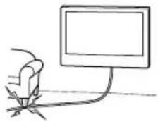
Do not allow the AC power cord or the connecting cable to be pinched.
If the AC power cord or the connecting cable is pinched between the unit and the wall or is bent or twisted by force, the internal conductors may become exposed and cause a short circuit or an electrical break. This may cause a fire or an electric shock.
natural_image
Simple line drawing of a hand holding a computer monitor connected to a cable (no text or symbols)Table of Contents
Before getting started 4
What is your wall made of? 4
Supplied items 5
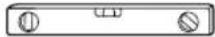
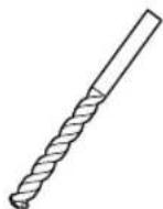
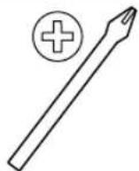
Tools needed 5
A Attaching TV to the Dry Wall with Studs....6
Installing the Lateral Shift Bracket to the wall....6
Preparing for the installation of the TV....10
Installing the TV on the wall....11
B Attaching the Wall-Mount Bracket to the Solid Concrete or Concrete Block....14
Installing the Wall-Mount Bracket to the wall....14
Preparing for the installation of the TV....18
Installing the TV on the wall....19
Specifications....22
Before getting started
Firstly, check the type of the wall to install the TV.
The Wall-Mount Bracket differs depending on the type of the wall.
What is your wall made of?
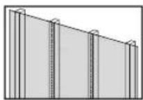
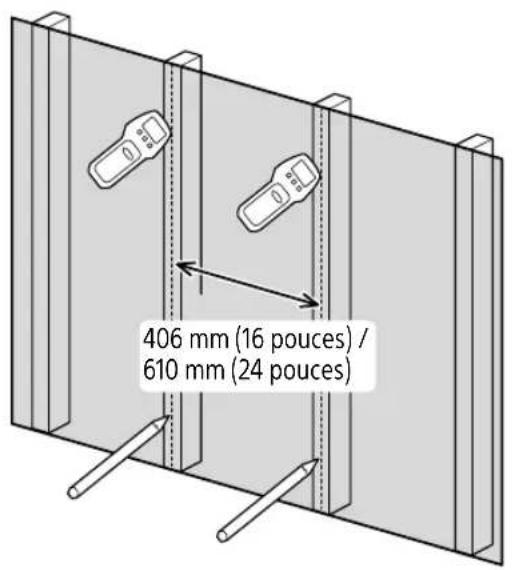
Dry wall with studs
Precautions
• Maximum dry wall thickness: 16 mm (5/8 inch).
- Ensure that the inner wood stud size is at least 51 x 102 mm (2 x 4 inch) for common or 38 x 89 mm (1 1/2 x 3 1/2 inch) for nominal.
- Keep minimum 406 mm (16 inch) horizontal space between fasteners.

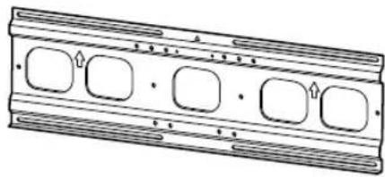
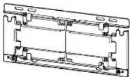
Use the Lateral Shift Bracket.
natural_image
Technical line drawing of a mechanical component with four rounded square cutouts (no text or symbols)+
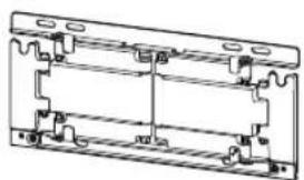
natural_image
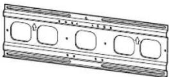
Technical line drawing of a mechanical bracket assembly (no text or symbols)Solid Concrete or Concrete Block
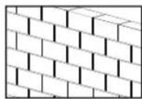
Precautions
- Mount the Wall-Mount Bracket directly onto the solid concrete wall.
- Ensure that the thickness of solid concrete wall is at least 203 mm (8 inch).
- Ensure that the size of each concrete block is at least 203 x 203 x 406 mm (8 x 8 x 16 inch).

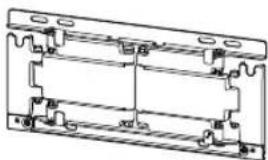
Use the Wall-Mount Bracket.
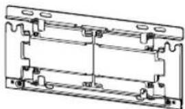
natural_image
Technical line drawing of a mechanical bracket assembly (no text or symbols)
Supplied items
WM1V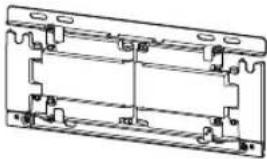 | WM5W (2)(2) (2)(2) | *3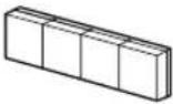  | 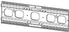 |
  6 mm x 23 mm(1/4 inch x29/32 inch)(2) 6 mm x 23 mm(1/4 inch x29/32 inch)(2) |   6 mm x 13 mm(1/4 inch x17/32 inch)(2) 6 mm x 13 mm(1/4 inch x17/32 inch)(2) |   8 mm x 15 mm(11/32 inch x19/32 inch)(6) 8 mm x 15 mm(11/32 inch x19/32 inch)(6) |  |
  | 8 mm x 60 mm(11/32 inch x2 3/8 inch)(6) |   (6) (6) |  *2 *2 (6) (6) |

Tools needed
*1 |  |  |  |  |
| 5.5 mm(7/32 inch) | 10 mm(13/32 inch) | |||
 | *2 | (c37c) |  | 13 mm(1/2'') |
| 1.5 N.m/1,5 N.m{15 kgf.cm} | 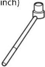 | |||
| 12.5 N.m/12,5 N.m{130 kgf.cm} | ||||
 | ||||
*1 Only for dry wall with studs
*2 Only for solid concrete or concrete block
*3 Only for 75 inch (189.3 cm) model
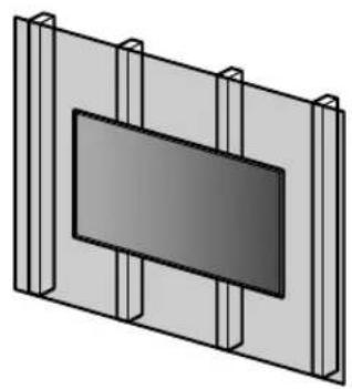
A Attaching TV to the Dry Wall with Studs
Dry wall with studs
natural_image
3D diagram of a rectangular panel with vertical supports and a central dark rectangle (no text or symbols)WM5
natural_image
Technical line drawing of a rectangular mechanical component with four rounded square cutouts and horizontal grooves (no text or symbols)WM1
+
natural_image
Technical line drawing of a mechanical assembly with mounting brackets and housing (no text or symbols)Installing the Lateral Shift Bracket to the wall
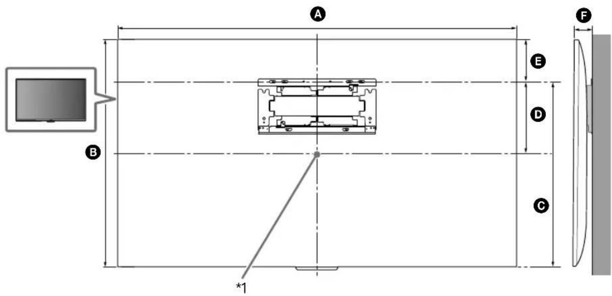
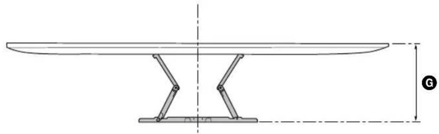
1 Decide on the installation location.
Make sure that the wall has enough space for the TV and is capable of supporting a weight of at least six times that of the TV.
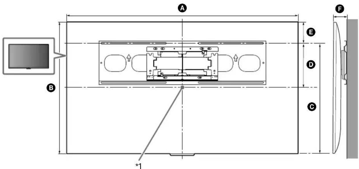
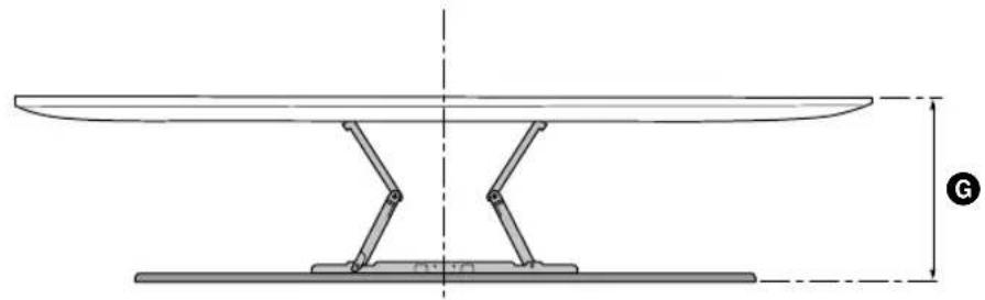
natural_image
Technical line drawing of a table with support legs and a vertical dimension line, no text or symbols present
natural_image
Diagram of a mechanical lever system with a curved blade and pivot, showing angle H (no text or symbols)(mm/inch)
| XBR | ABC | DEFG | H^*2 (°) | |||||
| 75X940E | 1,673 / 65 7/8 | 962 / 37 7/8 | 716 / 28 1/4 | 230 / 9 1/8 | 246 / 9 3/4 | 87 / 3 1/2 | 339 / 13 3/8 | 15 |
| 65X930E | 1,451 / 57 1/4 | 838 / 33 | 691 / 27 1/4 | 268 / 10 5/8 | 147 / 5 7/8 | 59 / 2 3/8 | 309/ 12 1/4 | 15 |
TV installation dimensions table (mm/inch)
Figures in the table may differ slightly depending on the installation.
*1 (Screen center point)
*2 (Approx.)
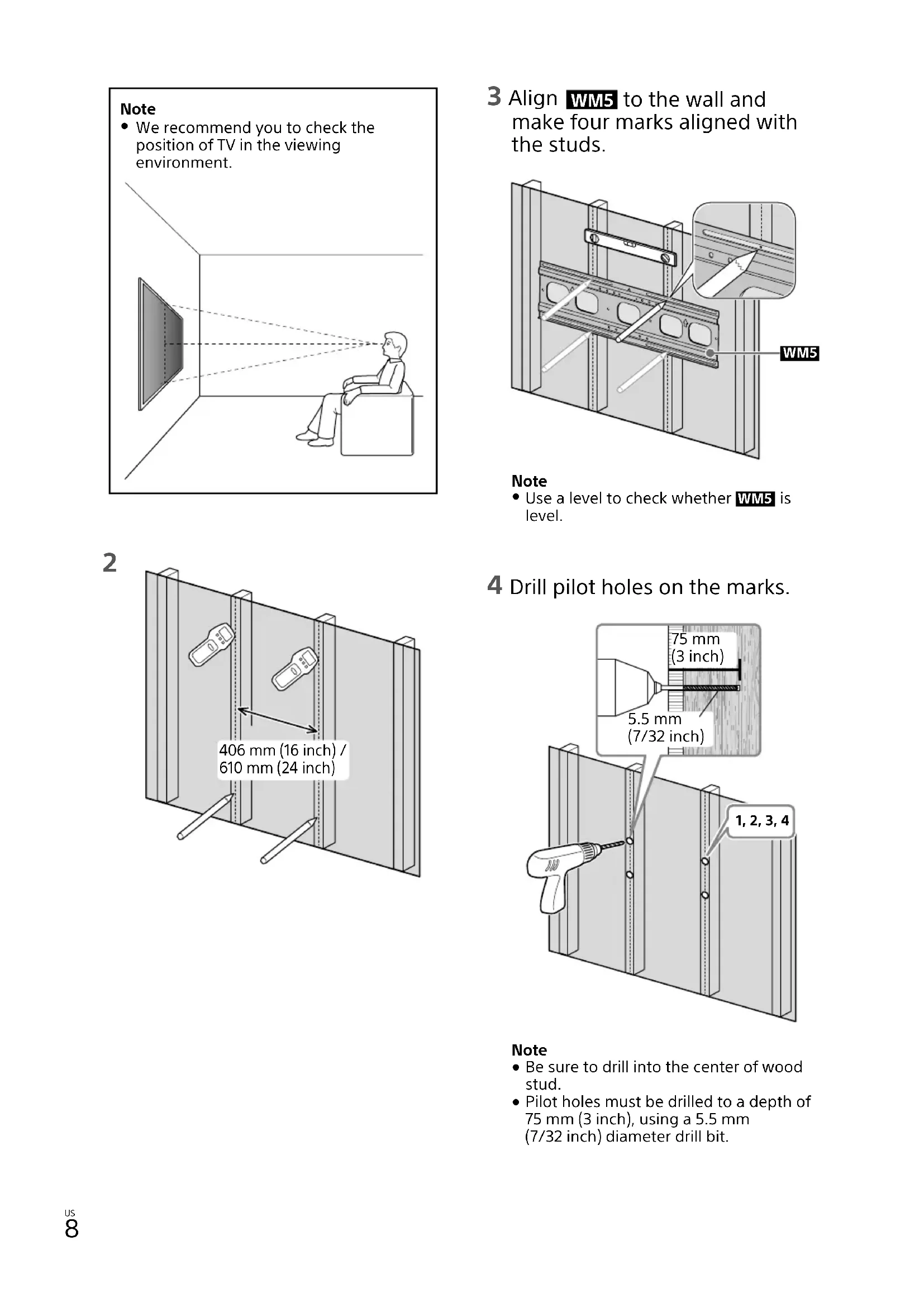
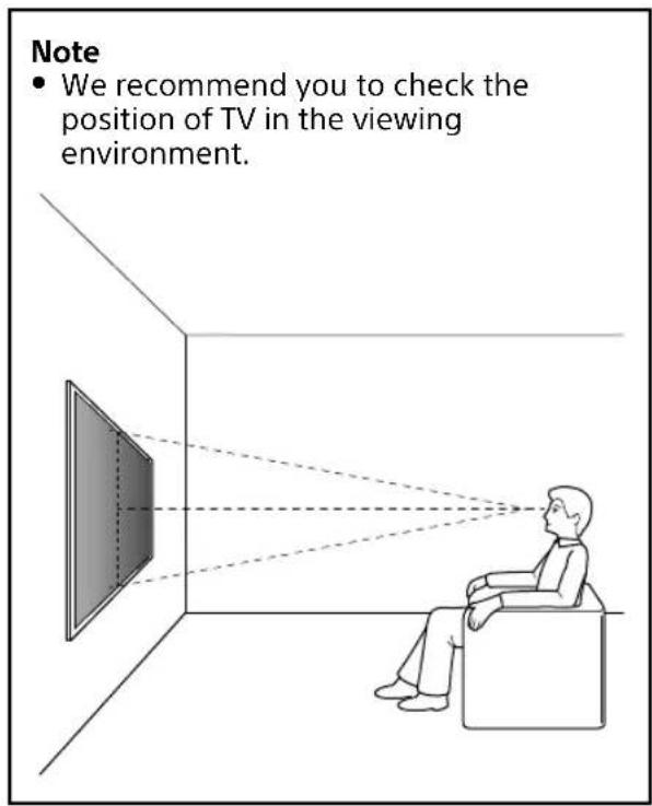
Note
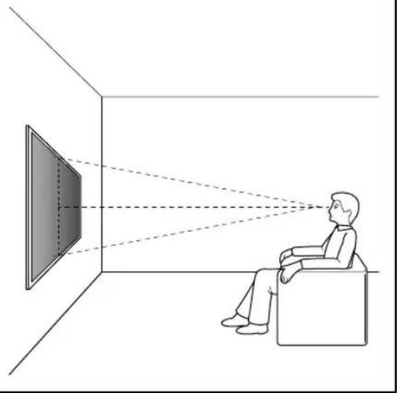
• We recommend you to check the position of TV in the viewing environment.
natural_image
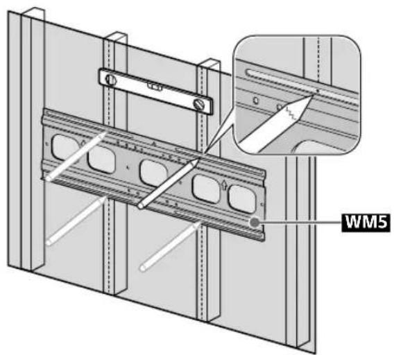
Illustration of a person sitting in a chair facing a screen with dashed lines indicating perspective projection (no text or symbols)3 Align WM5 to the wall and make four marks aligned with the studs.
Note
- Use a level to check whether WM5 is level.
2

4 Drill pilot holes on the marks.
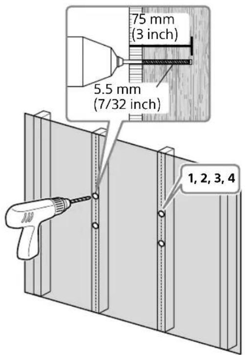
Note
- Be sure to drill into the center of wood stud.
- Pilot holes must be drilled to a depth of 75 mm (3 inch), using a 5.5 mm (7/32 inch) diameter drill bit.
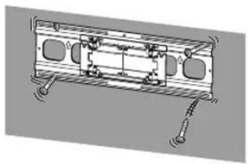
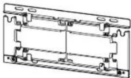
5
natural_image
3D mechanical assembly diagram showing three sequential views of a bracket with scissors and mounting holes (no text or symbols)6 Install WM5 on the wall.
Note
- Use a level to check whether the Lateral Shift Bracket is level.
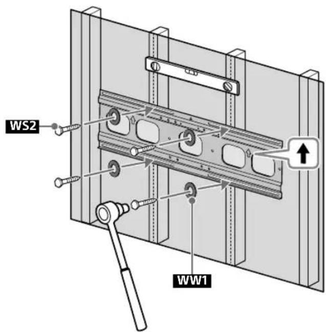
Precaution
- Do not over-tighten the lag bolts WS2. Improper tightening could reduce the holding power of the lag bolts WS2.
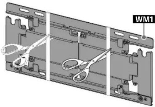
7 Attach WM1 to WM5 on the wall.
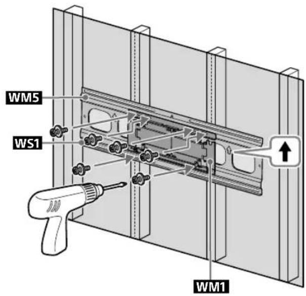
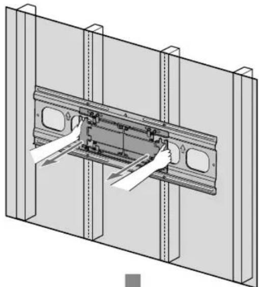
8 Pull out the arm of the bracket to the end.
natural_image
Technical illustration of a mechanical assembly with hands installing components on a metal frame (no text or symbols)
natural_image
Technical line drawing of a structural assembly with two panels and mounting brackets (no text or symbols)Preparing for the installation of the TV
1
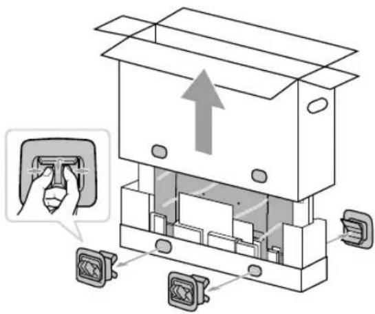
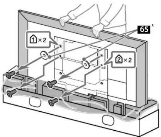
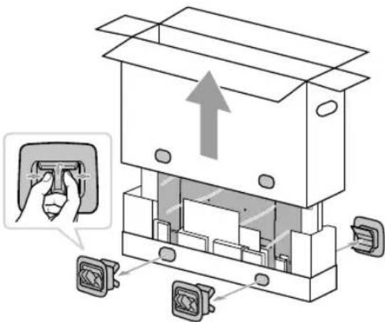
2 Remove the screws and spacers from the rear of the TV.

* 65 inch (163.9 cm) model only
Precaution
- If the Table-Top Stand is already attached to the TV, be sure to attach the Wall-Mount Bracket parts to the TV before detaching the Table-Top Stand.
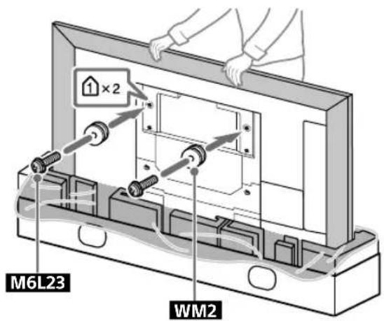
3

4 Attach the WM4 to the TV (75 inch (189.3 cm) model only).
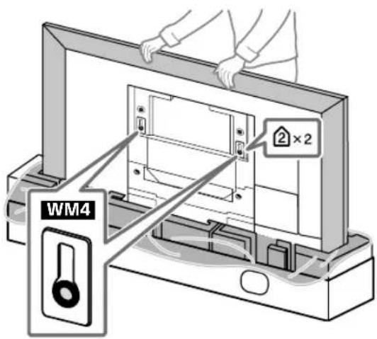
Installing the TV on the wall
1

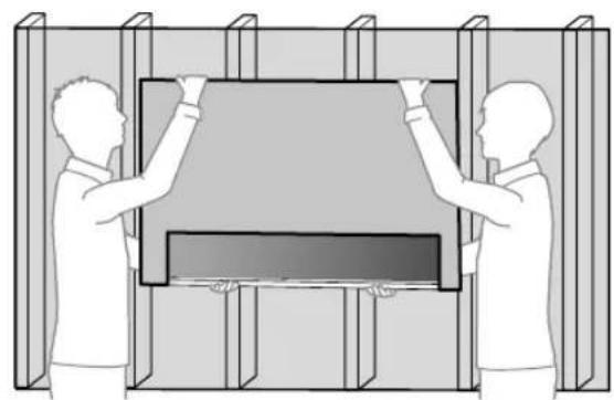
natural_image
Illustration of two people assembling a large TV or monitor frame (no text or symbols visible)3
natural_image
3D diagram of a mechanical assembly with a central component and two vertical supports (no text or symbols)2
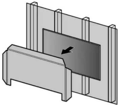
natural_image
Two people installing or adjusting a rectangular panel inside a structural frame (no text or symbols visible)4

natural_image
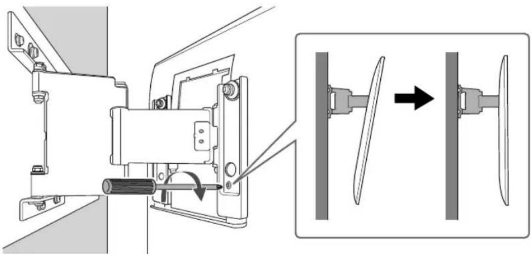
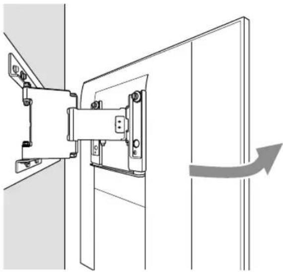
Technical line drawing of a mechanical assembly with a directional arrow indicating motion (no text or symbols)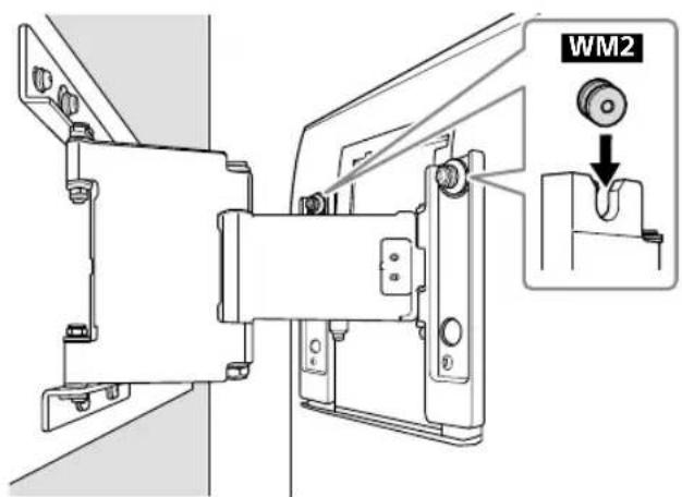
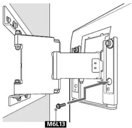
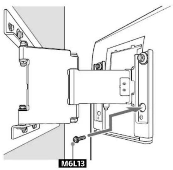
5 Screw the left and right side of the Wall-Mount Bracket to adjust the angle of the TV.
natural_image
Mechanical assembly diagram showing a motor and fan assembly with directional arrows (no text or labels)6
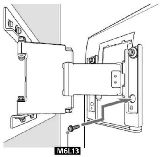
natural_image
Technical line drawing of a mechanical assembly with mounting brackets and a labeled component M6L13 (no readable text or symbols beyond label)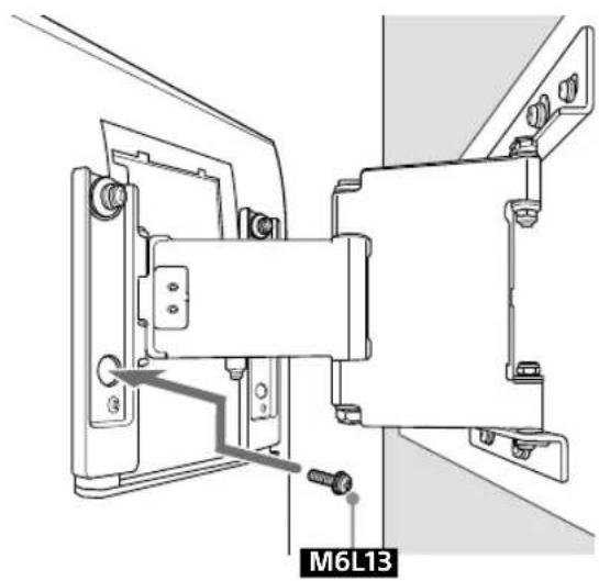
natural_image
Technical line drawing of a mechanical assembly with mounting brackets and a labeled component M6L13 (no readable text or symbols beyond label)7
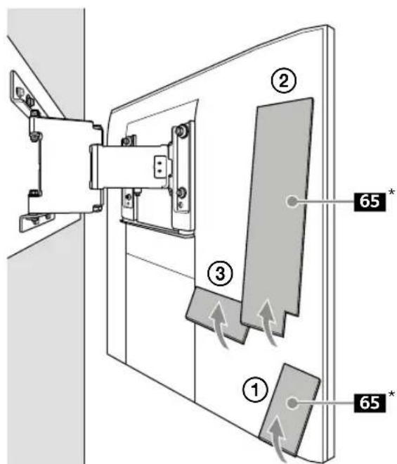
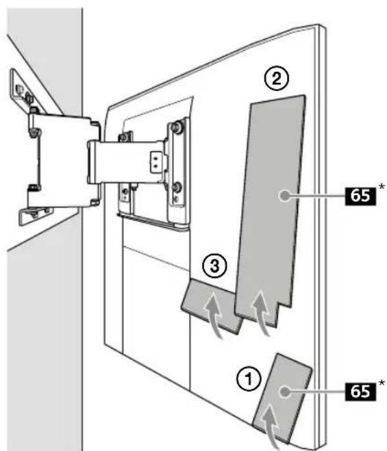
* 65 inch (163.9 cm) model only
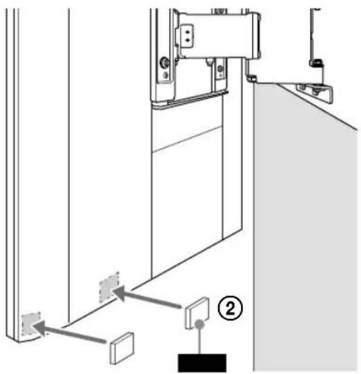
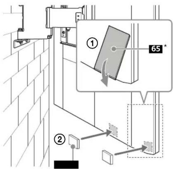
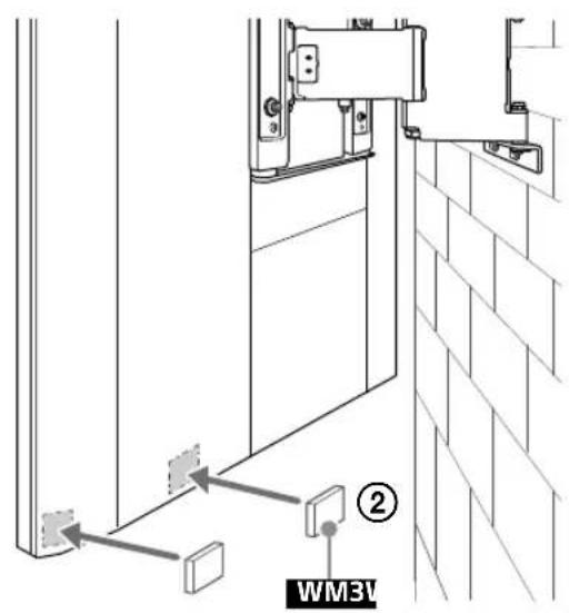
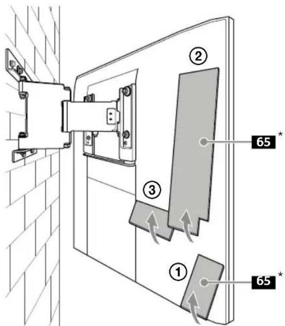
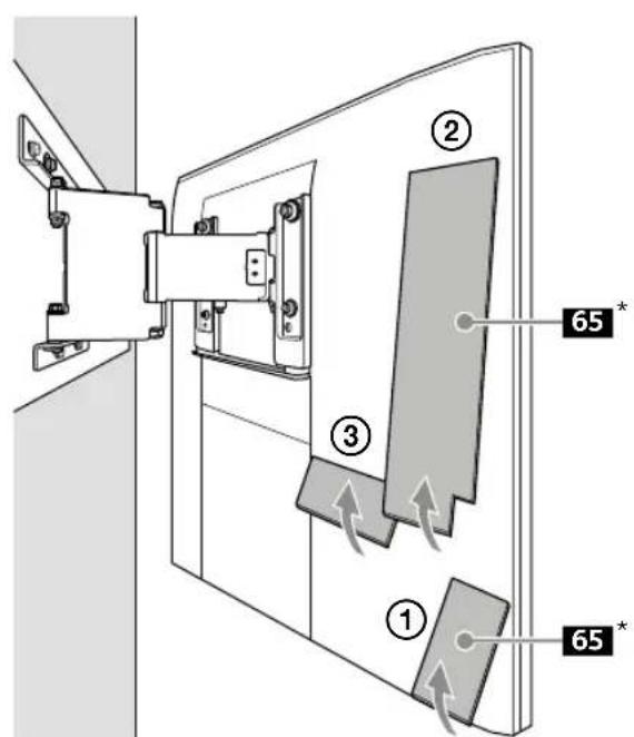
8 Attach WM3.
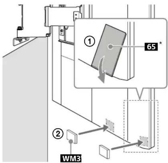
* 65 inch (163.9 cm) model only
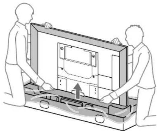
10 When moving the TV, hold it firmly from the bottom.
9

natural_image
Diagram of a cable installation or piping system with a connector and directional arrow (no text or symbols)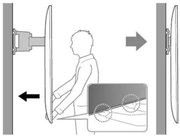
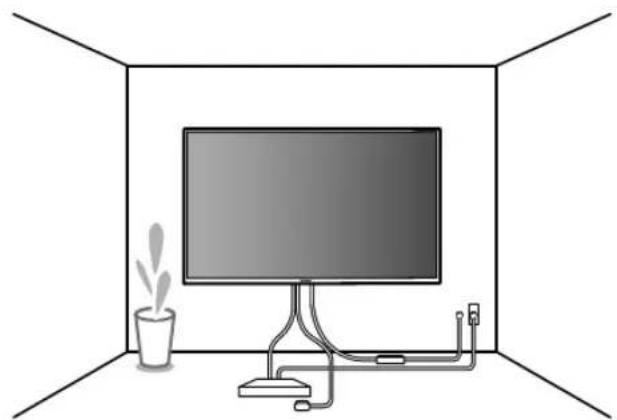
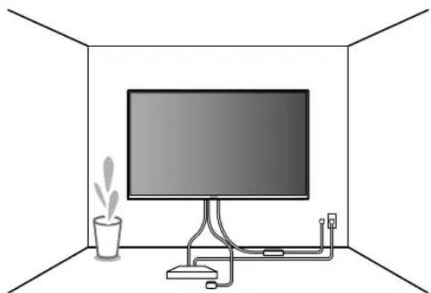
11
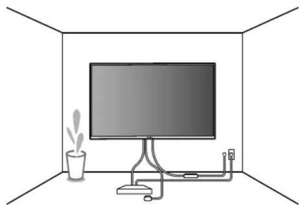
natural_image
Interior view of a room with a monitor, cable, and a potted plant (no text or symbols)B Attaching the Wall-Mount Bracket to the Solid Concrete or Concrete Block
Solid Concrete or Concrete Block
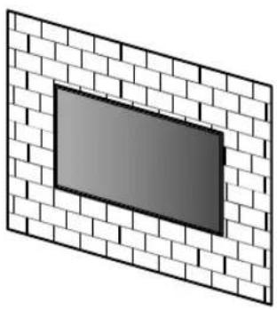
natural_image
Diagram of a brick wall with a rectangular window, no text or symbols present
natural_image
Technical line drawing of a mechanical bracket assembly (no text or symbols)Installing the Wall-Mount Bracket to the wall
1 Decide on the installation location.
Make sure that the wall has enough space for the TV and is capable of supporting a weight of at least six times that of the TV.
natural_image
Technical line drawing of a table with a curved top and vertical support structure, labeled 'G' (no text or symbols on the diagram itself)
natural_image
Technical line drawing of a mechanical lever system with no text or symbols(mm/inch)
| XBR | ABC | DEFG | H^*2(°) | |||||
| 75X940E | 1,673 / 65 7/8 | 962 / 37 7/8 | 685 / 27 | 199 / 7 7/8 | 277 / 11 | 73 / 2 7/8 | 325 / 12 7/8 | 15 |
| 65X930E | 1,451 / 57 1/4 | 838 / 33 | 660 / 26 | 237 / 9 3/8 | 178 / 7 1/8 | 45 / 1 13/16 | 295 / 11 5/8 | 15 |
TV installation dimensions table (mm/inch)
Figures in the table may differ slightly depending on the installation.
*1 (Screen center point)
*2 (Approx.)
2 Align WM1 to the wall and make six marks.
3 Drill pilot holes on the marks.
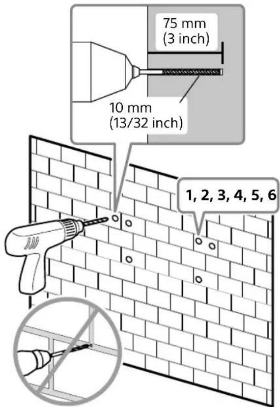
Note
- Use a level to check whether WM1 is level.
4
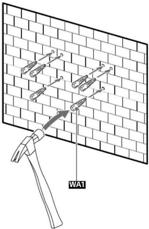
5
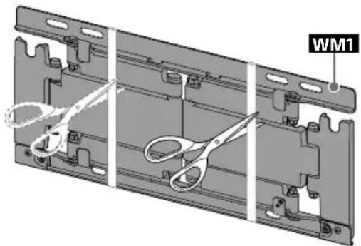
natural_image
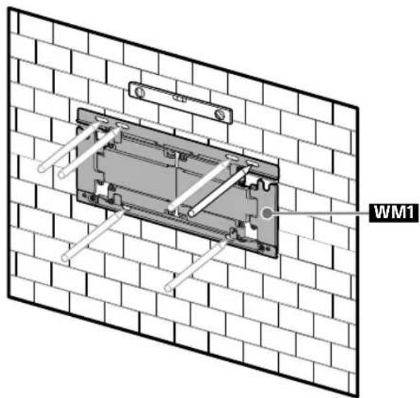
3D mechanical assembly diagram showing three views of a bracket with scissors and mounting holes (no text or symbols)6 Install WM1 on the wall.
Note
- Use a level to check whether the Wall-Mount Bracket is level.
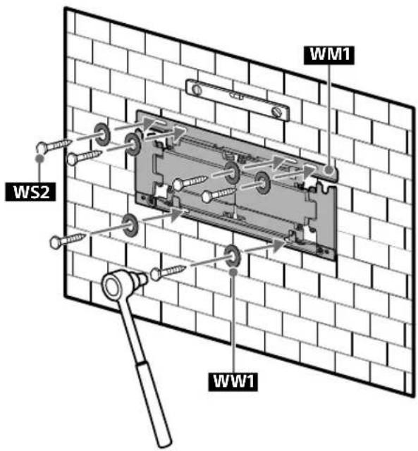
Precaution
- Do not over-tighten the lag bolts WS2. Improper tightening could reduce the holding power of the lag bolts WS2.
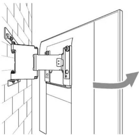
7 Pull out the arm of WM1 to the end.
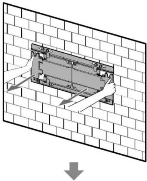
natural_image
Diagram showing hands installing or adjusting a mechanical component on a brick wall, with no text or symbols present.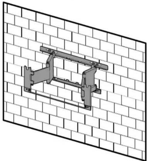
natural_image
Technical line drawing of a mechanical bracket mounted on a brick wall (no text or symbols)Preparing for the installation of the TV
1

2 Remove the screws and spacers from the rear of the TV.
* 65 inch (163.9 cm) model only
Precaution
- If the Table-Top Stand is already attached to the TV, be sure to attach the Wall-Mount Bracket parts to the TV before detaching the Table-Top Stand.
3
4 Attach the WM4 to the TV (75 inch (189.3 cm) model only).

Installing the TV on the wall
1
natural_image
Illustration of two people assembling a large electronic device with a central panel (no text or symbols visible)3

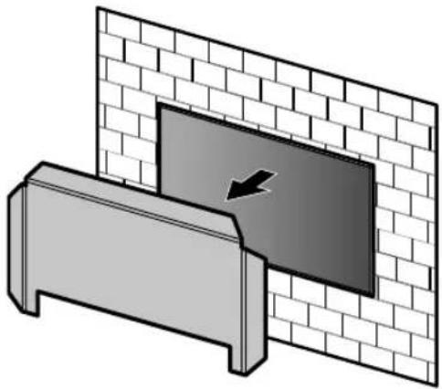
natural_image
Diagram showing a wall-mounted device with a black arrow pointing to a panel, mounted on a base (no text or symbols present)2
natural_image
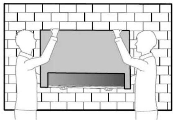
Illustration of two people installing or adjusting a large rectangular object on a brick wall (no text or symbols)
4

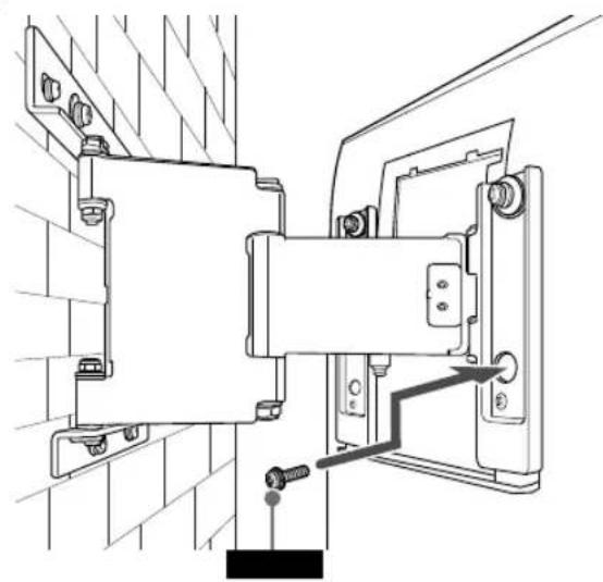
natural_image
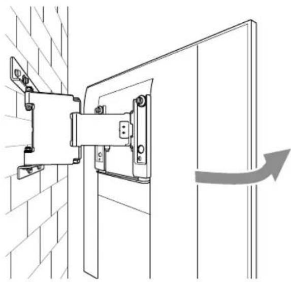
Technical line drawing of a mechanical bracket assembly mounted on a brick wall, with an arrow indicating direction (no text or symbols present)
US
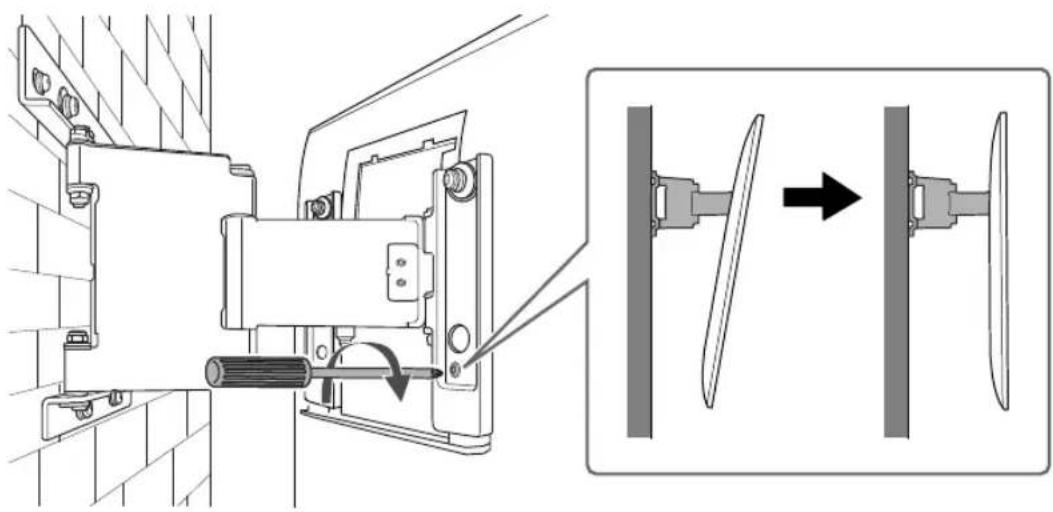
5 Screw the left and right side of the Wall-Mount Bracket to adjust the angle of the TV.
natural_image
Technical diagram showing mechanical assembly with tool and component alignment (no text or symbols)6
natural_image
Technical line drawing of a mechanical assembly with mounting brackets and a pipe connection (no text or symbols)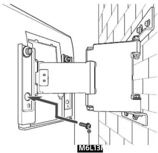
7

* 65 inch (163.9 cm) model only
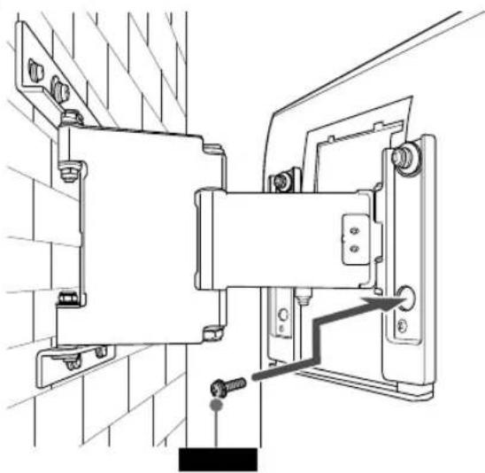
8 Attach WM3.
* 65 inch (163.9 cm) model only
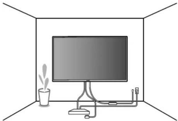
9 10, When moving the TV, hold it
firmly from the bottom.
11

natural_image
Interior view of a room with a monitor, cable, and a potted plant (no text or symbols)Specifications
WM5

WM1
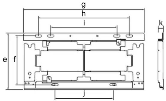
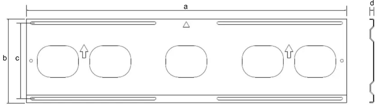
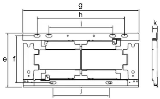
Dimension: (Approx.) (mm (inch))
a : 1,040 mm (41 inch)
b : 273 mm (10 3/4 inch)
c : 245 mm (9 3/4 inch)
d : 14 mm (9/16 inch)
e : 206 mm (8 1/8 inch)
f : 180 mm (7 1/8 inch)
g : 446 mm (17 5/8 inch)
h : 336 mm (13 1/4 inch)
i : 244 mm (9 5/8 inch)
j : 215 mm (8 1/2 inch)
k : 20 mm (13/16 inch)
Mass (base only): (Approx.)
WM5 4.9 kg / 10.8 lb.
WM1 2.7 kg / 6.0 lb.
Design and specifications are subject to change without notice.
Support de fixation murale
Sécurité
natural_image
Technical line drawing of a mechanical assembly with mounting holes and internal components (no text or symbols)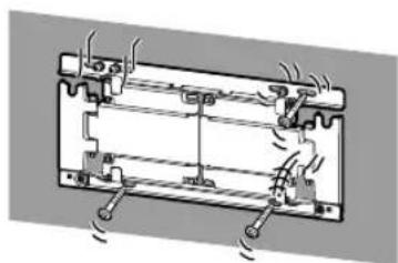
natural_image
Pure mechanical diagram of a battery or motor assembly without any text, numbers, or symbolsnatural_image
Technical line drawing of a rectangular mechanical component with four rounded square cutouts (no text or symbols)+
natural_image
Technical line drawing of a mechanical bracket assembly (no text or symbols)natural_image
Technical line drawing of a mechanical bracket assembly (no text or symbols)
Accessoires fournis
| (2) (2) | | | |
| 6 mm x 23 mm (1/4 pouces x 29/32 pouces) | 6 mm x 13 mm (1/4 pouces x 17/32 pouces) |  8 mm x 15 mm (11/32 pouces x 19/32 pouces) 8 mm x 15 mm (11/32 pouces x 19/32 pouces) |  | |
| [x5C8] | 8 mm x 60 mm (11/32 pouces x 2 3/8 pouces) |   |  *2 *2 | (6) |

Outils requis
*1
natural_image
Pure diagram of a rectangular frame with vertical supports and a central dark rectangle (no text or symbols)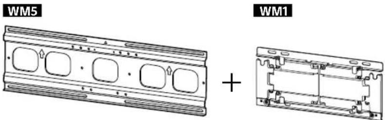
natural_image
Technical line drawing of a table with support legs and a vertical dimension line, no text or symbols present
natural_image
Diagram of a mechanical lever system with a curved blade and pivot, showing angle H (no text or symbols)(mm/pouces)
| XBR | ABC | DEFG | H^*2 (°) | |||||
| 75X940E | 1 673 /65 7/8 | 962 /37 7/8 | 716 /28 1/4 | 230 /9 1/8 | 246 /9 3/4 | 87 /3 1/2 | 339 /13 3/8 | 15 |
| 65X930E | 1 451 /57 1/4 | 838 /33 | 691 /27 1/4 | 268 /10 5/8 | 147 /5 7/8 | 59 /2 3/8 | 309/12 1/4 | 15 |
natural_image
Illustration of a person sitting in a chair facing a screen with dashed lines indicating perspective projection (no text or symbols)2
natural_image
3D mechanical assembly diagram showing three views of a bracket with scissors and mounting holes (no text or symbols)natural_image
Technical diagram of a mechanical assembly with hands operating a bracket (no text or symbols present)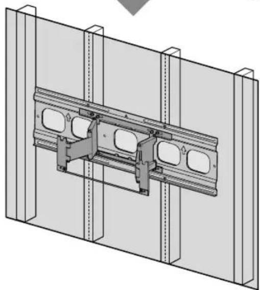
natural_image
Technical diagram of a structural assembly with two parallel panels and internal components (no text or symbols)1

natural_image
Illustration of two people assembling a large TV frame with a mechanical component, no text or symbols present3

natural_image
3D diagram of a mechanical assembly with a central component and two vertical supports (no text or symbols)2

natural_image
Two people installing or adjusting a rectangular panel inside a structural frame (no text or symbols visible)
4

natural_image
Technical line drawing of a mechanical assembly with a directional arrow indicating motion (no text or symbols)FR

natural_image
Technical diagram showing mechanical assembly with a component being inserted, then assembled into a vertical panel (no text or symbols present)6
natural_image
Technical line drawing of a mechanical assembly with mounting brackets and a labeled component M6L13 (no readable text or symbols beyond label)
7
9
natural_image
Diagram of a cable installation with a connector and directional arrow (no text or symbols)11

natural_image
Interior view of a room with a monitor, cable, and a potted plant (no text or symbols)natural_image
Diagram of a brick wall with a rectangular window, no text or symbols present
natural_image
Technical line drawing of a mechanical bracket assembly (no text or symbols)natural_image
Technical line drawing of a table with support legs and a vertical dimension line, no text or symbols present
natural_image
Technical line drawing of a curved mechanical lever with a stand and angle annotation (no text or symbols)(mm/pouces)
| XBR | ABC | DEFG | H^*2 (°) | |||||
| 75X940E | 1 673 /65 7/8 | 962 /37 7/8 | 685 /27 | 199 /7 7/8 | 277 /11 | 73 /2 7/8 | 325 /12 7/8 | 15 |
| 65X930E | 1 451 /57 1/4 | 838 /33 | 660 /26 | 237 /9 3/8 | 178 /7 1/8 | 45 /1 13/16 | 295 /11 5/8 | 15 |
natural_image
Illustration of a person sitting in a chair viewing a wall-mounted screen, with dashed lines indicating perspective projection (no text or symbols)natural_image
3D mechanical assembly diagram showing three views of a bracket with cutouts and a labeled component 'WM1' (no text or symbols beyond label)Précautions
natural_image
Diagram showing hands installing or adjusting a mechanical component on a brick wall, with no text or symbols present.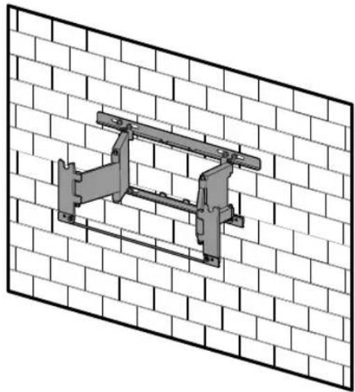
natural_image
Technical illustration of a mechanical bracket mounted on a brick wall (no text or symbols)1

natural_image
Illustration of two people assembling a large TV frame with a mechanical component, no text or symbols present3
natural_image
Diagram showing a brick wall with a black arrow pointing to a panel, next to a metal bracket (no text or symbols)2

natural_image
Two people installing a large rectangular object on a brick wall (no text or symbols visible)4
natural_image
Technical line drawing of a wall-mounted bracket assembly with a directional arrow indicating motion (no text or symbols)

FR
natural_image
Technical diagram showing a mechanical assembly with an arrow indicating motion, no text or symbols present6

natural_image
Technical line drawing of a mechanical assembly with mounting brackets and a pipe connection (no text or symbols)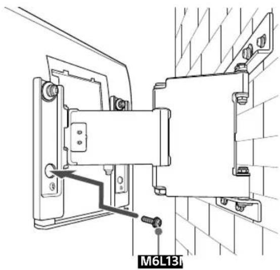
7
natural_image
Technical line drawing of a ceiling-mounted cable with a wall-mounted connector and a directional arrow indicating upward movement (no text or symbols present)11
natural_image
Interior view of a room with a monitor, cable, and a potted plant (no text or symbols)Spécifications
WM5

WM1

natural_image
Technical line drawing of a mechanical assembly with mounting holes and internal components (no text or symbols)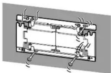
natural_image
Technical diagram of a battery pack with cooling fins and heat exchangers (no text or labels)natural_image
Technical line drawing of a rectangular mechanical component with four rounded cutouts and side grooves (no text or symbols)+
natural_image
Technical line drawing of a mechanical bracket assembly (no text or symbols)natural_image
Technical line drawing of a mechanical bracket assembly (no text or symbols)
natural_image
3D diagram of a rectangular panel with vertical supports and a central black rectangle (no text or symbols)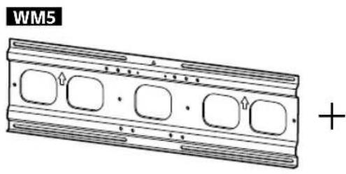
natural_image
Technical line drawing of a mechanical component with four rounded square holes and a plus sign (no text or symbols on the diagram itself)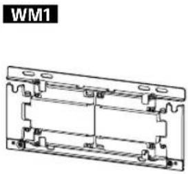
natural_image
Technical line drawing of a mechanical bracket assembly (no text or symbols)natural_image
Technical line drawing of a table with support legs and a vertical dimension line, no text or symbols present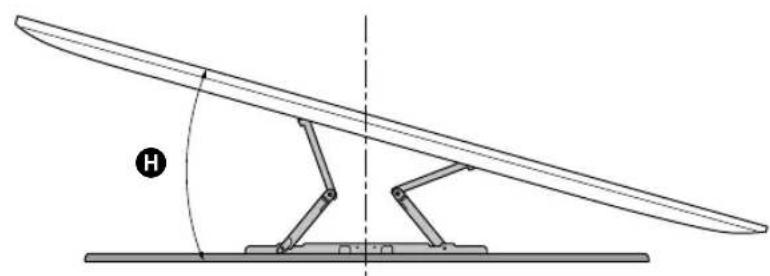
natural_image
Diagram of a mechanical lever system with a curved blade and pivot, showing angle H (no text or symbols)(mm/pulgadas)
| XBR | ABC | DEFG | H^*2 (°) | |||||
| 75X940E | 1 673 /65 7/8 | 962 /37 7/8 | 716 /28 1/4 | 230 /9 1/8 | 246 /9 3/4 | 87 /3 1/2 | 339 /13 3/8 | 15 |
| 65X930E | 1 451 /57 1/4 | 838 /33 | 691 /27 1/4 | 268 /10 5/8 | 147 /5 7/8 | 59 /2 3/8 | 309/12 1/4 | 15 |
natural_image
Illustration of a person sitting in a chair facing a screen with dashed light rays, no text or symbols presentnatural_image
3D mechanical assembly diagram showing three views of a bracket with scissors and mounting holes (no text or symbols)6 Instale WM5 en la pared.
Nota
natural_image
Technical diagram showing a mechanical assembly with hands operating a bracket (no text or symbols present)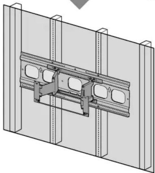
natural_image
Technical diagram of a structural assembly with two parallel panels and internal components (no text or symbols)1

natural_image
Illustration of two people assembling a large TV panel with an upward arrow indicating motion (no text or symbols present)3

natural_image
3D diagram of a mechanical assembly with a central component and two vertical supports (no text or symbols)2

natural_image
Two people installing or adjusting a rectangular panel inside a structural frame (no text or symbols visible)4
natural_image
Technical line drawing of a mechanical assembly with a directional arrow indicating motion (no text or symbols)ES

natural_image
Mechanical assembly diagram showing a valve mechanism with directional arrows indicating motion (no text or symbols present)6
natural_image
Technical line drawing of a mechanical assembly with mounting brackets and a labeled component M6L13 (no readable text or symbols beyond label)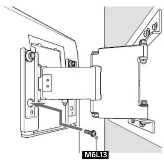
7
natural_image
Diagram of a cable installation or wiring connection with a connector and directional arrow (no text or symbols)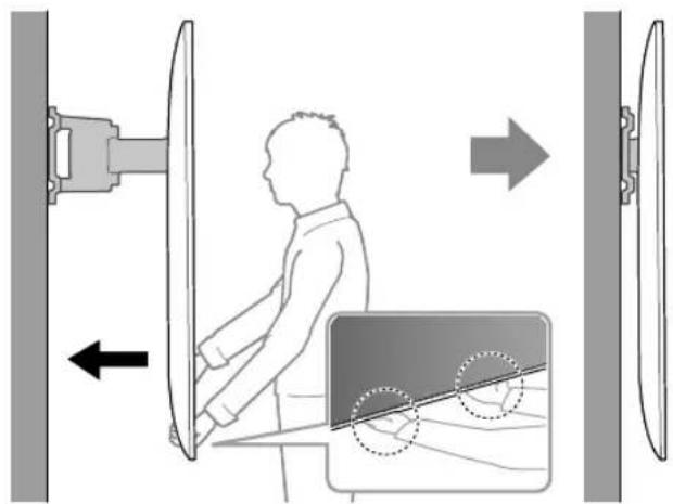
ES
11
natural_image
Interior view of a room with a monitor, cable, and a potted plant (no text or symbols)natural_image
Diagram of a brick wall with a rectangular window, no text or symbols present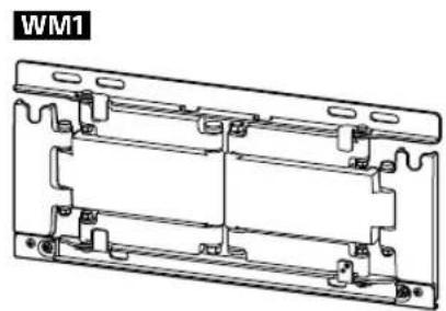
natural_image
Technical line drawing of a mechanical bracket assembly (no text or symbols)natural_image
Technical line drawing of a table with a curved top and two vertical supports, labeled 'G' at the base (no text or symbols on the diagram itself)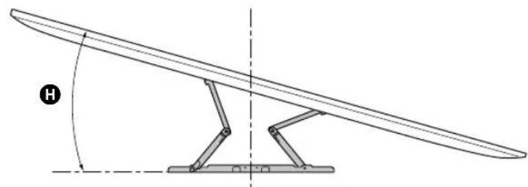
natural_image
Technical line drawing of a curved mechanical lever with a stand and angle indicator (no text or symbols)(mm/pulgadas)
| XBR | ABC | DEFG | H^*2 (°) | |||||
| 75X940E | 1 673 /65 7/8 | 962 /37 7/8 | 685 /27 | 199 /7 7/8 | 277 /11 | 73 /2 7/8 | 325 /12 7/8 | 15 |
| 65X930E | 1 451 /57 1/4 | 838 /33 | 660 /26 | 237 /9 3/8 | 178 /7 1/8 | 45 /1 13/16 | 295 /11 5/8 | 15 |
natural_image
3D mechanical assembly diagram showing three views of a bracket with scissors and mounting holes (no text or symbols)6 Instale WM1 en la pared.
Nota
Precauciones
natural_image
Diagram showing hands installing or adjusting a mechanical component on a brick wall, with no text or symbols present.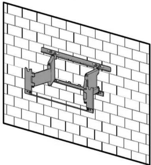
natural_image
Technical illustration of a structural frame mounted on a brick wall (no text or symbols)1
natural_image
Illustration of two people assembling a large electronic device with a central panel (no text or symbols visible)3

natural_image
Diagram showing a wall-mounted device with a black arrow pointing to a panel, mounted on a base (no text or symbols present)2
natural_image
Illustration of two people installing or adjusting a large rectangular object on a brick wall (no text or symbols)
4
natural_image
Technical line drawing of a mechanical bracket mounted on a brick wall, with an arrow indicating direction (no text or symbols present)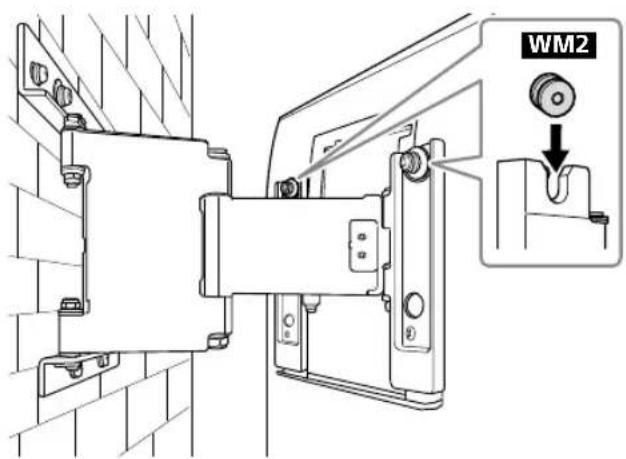
natural_image
Technical diagram showing a mechanical assembly with an inset view of a blade being inserted into a vertical panel (no text or symbols present)6
natural_image
Technical line drawing of a mechanical assembly with mounting brackets and a central component (no text or symbols)
natural_image
Technical line drawing of a mechanical assembly with mounting brackets and a labeled component (M6L13I), no readable text or symbols beyond the label.7

natural_image
Technical diagram showing cable installation with a pipe connection and directional arrow (no text or symbols)11
natural_image
Interior view of a room with a monitor, cable, and a potted plant (no text or symbols)Especificaciones
WM5
WM1
Peso (solo de la base): (Aprox.)

- To Customers
- PROFESSIONAL INSTALLATION REQUIRED
- To Sony dealers
- CAUTION
- Specified products
- WARNING
- Be sure to subcontract the installation to licensed contractors and keep small children away during the installation.
- Be sure to subcontract moving or dismounting of the TV to licensed contractors.
- Do not remove screws, etc., after mounting the TV.
- Do not make alterations to the parts of the Wall-Mount Bracket.
- Do not mount any equipment other than the specified product.
- Do not apply any load other than the TV on the Wall-Mount Bracket. Do not shake the TV left/right, up/down.
- Do not lean on or hang from the TV.
- Do not handle the product with excessive force during cleaning or maintenance.
- Precautions
- Installing the Wall-Mount Bracket
- Do not install the Wall-Mount Bracket on wall surfaces where the corners or the sides of the TV protrude away from the wall surface.
- Do not install the TV over or under an air-conditioner.
- Be sure to install the Wall-Mount Bracket securely to the wall following the instructions in this instruction manual.
- Be sure to assemble the bracket properly following the instructed procedure explained in this instruction manual.
- Be sure to tighten the screws securely in the designated position.
- Be careful not to subject the TV to shock during installation.
- Be sure to install the TV on a wall that is both perpendicular and flat.
- After proper installation of the TV, secure the cables properly.
- Do not allow the AC power cord or the connecting cable to be pinched.
- Table of Contents
- Before getting started
- What is your wall made of?
- Supplied items
- Tools needed
- A Attaching TV to the Dry Wall with Studs
- Installing the Lateral Shift Bracket to the wall
- Decide on the installation location.
- Note
- 2
- Install WM5 on the wall.
- Precaution
- Attach WM1 to WM5 on the wall.
- Pull out the arm of the bracket to the end.
- Preparing for the installation of the TV
- Installing the TV on the wall
- B Attaching the Wall-Mount Bracket to the Solid Concrete or Concrete Block
- Installing the Wall-Mount Bracket to the wall
- Install WM1 on the wall.
- Specifications
- Dimension: (Approx.) (mm (inch))
- Mass (base only): (Approx.)
- Support de fixation murale
- Sécurité
- Accessoires fournis
- Outils requis
- Précautions
- Spécifications
- Instale WM5 en la pared.
- Nota
- Instale WM1 en la pared.
- Precauciones
- Especificaciones
- Peso (solo de la base): (Aprox.)
Brand : SONY
Model : SUWL830
Category : Wall mount