SP 466 - Saw STIGA - Free user manual and instructions
Find the device manual for free SP 466 STIGA in PDF.
| Product type | Chainsaw |
| Brand | STIGA |
| Model | SP 466 |
| Engine | 2-stroke, air-cooled, powered by gasoline-oil mixture (2.5%) |
| Chain brake | Yes, manual (front hand guard) |
| Starting | Manual via recoil starter |
| Chain lubrication | Automatic, adjustable (oil pump) |
| Anti-freeze system | Yes, anti-freeze cap for temperatures < 5°C |
| Safety devices | Chain brake, front and rear guards, stop switch |
| Periodic maintenance | Air filter cleaning (8-10 h), spark plug check, chain sharpening |
| Intended use | Felling, cross-cutting, pruning (amateur use) |
| Fuel | Unleaded gasoline (min. 90 N.O.) + 2-stroke synthetic oil (JASO FC) |
| Included accessories | Bar, chain, mounting wrench, chain file |
| Category | Saw |
Frequently Asked Questions - SP 466 STIGA
User questions about SP 466 STIGA
0 question about this device. Answer the ones you know or ask your own.
Ask a new question about this device
Download the instructions for your Saw in PDF format for free! Find your manual SP 466 - STIGA and take your electronic device back in hand. On this page are published all the documents necessary for the use of your device. SP 466 by STIGA.
USER MANUAL SP 466 STIGA
6. USO DELLA MACCHINA
CNMBOJIbT 10Ka3Ba ONaCHOCT.
Hecna3BaHeTo Ha npedeynpeJdeHneTo BOIN DO Bb3MOKHOCTTa OT IInuHN HapaHbAHn INn HapaHbAHn HA TpeTn IInca N/INn HHaacnHe Ha 9eTn.
NaparpaΦte OT6eJI3aHn C KBaApat
CbC CNB TOUKO B KOHTyp, yKa3BaT
ONuHOHaJIHx XapaKTePcNTHKn, KOnTO He ca
IpeBnDeHn 3a BCnHKn MoJeN, OINCAHn
B ToBa pKOBoDCTBO. IpoBepTe DaJIn
CbOTBeTHaTa TexHnuecka XapaKTePcNTHa
e npEdBnDeHa 3a Baunr MoDen.
Bcunkn yka3aHnra "npedeH", "3aJeH", "deceH" n "IaB" ce OTHacr Tdo pa60thaT no3nua Ha onepaTopa.
1.2 CπPABHn
1.2.1 Φιγρη
ФигурптЕВTe3nHнCTpyKцИЗза ekCПLoaTaцЯ ca HOMepnpaHn1,2,3,N.T.H..
KOMnoHENTe nocoyHnHaФигурптEc
OT6eJIa3aHnC6yKBNTeA,B,CnT.H.
CnpabKaTа 3a KOMnoHENTa C Ha
Фигура2ce nocOuBa cHaJnica:"Bx.
Фиг.2.C"Ил npocTo"(Фиr.2.C)".
ФигурптЕca INHdINKaTINBn.DeIcTBNTeJHNTe
чacterMOKe Da ce pa3JIuYaBt OT Te3N,
KoINTO ca NOKa3aHn HaФигурпatura.
1.2.2 3aIabn
PbKOBOcTOe pa3dJeHo Ha rIaBn I naparpaФn. 3aIaBHeTo ha naparpaФ "2.1 O6yehne" e no3aIaBne Ha "2. IpaBnla 3a 6e30NaChocT". OTHacHnraTa Do 3aIaBn I nn naparpaФn ca OT6eJ3aHn CbC cbKpaSeHneto "rI." IIN "nap." n CbOTBeTHnI Homep. HanpImep: "rI. 2" IIN "nap. 2.1".
2. ПРавILA 3A БЕЗОПАСHОCT
2.1 OBOUEHNE
Pa3yete n CBHHete c HOMaHdnte N C NOxOJaTO H3NoJ3BaHe Ha MaunHaT. Hayete ce da n3KnIOvBaTe 6bp3o MaunHaT. HeCna3BaHeto NapeDynpexdeHnraTa n NHCTpyKunTe MOHe da npuHHn HHnJeHTn H/ Hn cepno3HN HapaHbAHn.
- HnKora He No3BOJRABaiTe MaunHaTa da 6bDe n3PON3BaHa OT Deca NIn OT Xopa, KOInTo He ca 3aNo3HaTn DOCTaTBuHO C INCTpyKUnTe. MecTHnTe 3aKOH MoKe Da npEdbNkDaT MNHmAlHa Bb3pact 3a npaBO Ha n3POn3BaHe.
- Aa He ce n3noJ3Ba HNKORA MaunHaTa, aKO NOTpe6nteJe yMOpEn nn Hepa3nOLOKeH, INI e npneJ IeKapCTBa, HApKOTnU, aIKOXOI ININ BpeHN 3a peΦJIeKcNTe IN BHIMaHNeTO My BeueCTBa.
He 3a6paBnTe, ye onepaTopbT nIN To3n, KOHTO n3NoJ3Ba MaunHaTa e OTROBOpEH 3a INuIeHTN n He npEeDBnDEHn CNTyaUuN, KOHTO MORaT da ce clyuat Ha dpyrN Xopa Hn Ha TExHa Co6CTBeHocT. YAcT OTOROBOPHOCTTA Ha Notpe6nte rnepeHkata Ha B3MOKHNte PNCKOBe Ha TepeHa, NO KOnTo TpA6Ba Da ca ce pa6OTn, KaKTo N B3eMaHETo Ha BCnKn PpeDnA3HN MepKn, Heo6XoDMn 3a rapaHTnpaHe Ha Herobata 6e30nacHOCT n Ta3n Ha DpyrIne Xopa, OC6eHo, KOraTO ce pa6OTn PO HaKIOHn, HepaBHn, Xlb3raBn nIN HeCTa6nIHn TepEHN.
BcIyau,ye nckate da daTe nn 3aemeTe MaunHaTa Ha HnKOrO,y6eTe ce,Ye Notpe6nteJrT ce e 3an03HaI C nHCTpyKuHTe 3a ekCnloaTaun,cbdprKaU Ce B NaCToAOTOpbKOBODCTBO.
Korato MaunHaTa Ce noJ3Ba 3a OTCnUaHe Ha DbpBeta N OTP3BaHe Ha KIOH, Ce n3nCKBa CneuaJIHo o6yehne.
IpeHnWeTe HdeHTnФKauHOHHte DaHHn Ha MaunHaTa Ha CbOTBETHte MeCTa Ha eTnKeTa, KOITo CE HAmnpa OT3aD Ha KOpuata Ha pbKOBOCTBOTO.
BAHHO 13non3BaHTe
NdeHTnΦHKaUHnHTe DaHHN, KOHTO Ca NocouEH Na NdeHTnΦHKaUHnHn EHTKET Ha npOdyHTa BCEHN T, KORAto Ce CBbp3BaTe COTOpuHa pa6oTnHnua.
BAHHO IprnMep Ha deKnapaunTa 3a CbOTBeTCTBnE Ce HAMnpa Ha nocJeHNTe CTpaHnHa pbKOBOCTBOTO.
3.4 OCHOBHN KOMNOHEHTN
MaunHata ce cBcToI OT CneHnTe OCHOBN KOMNOHEHTN (ΦnR.1):
A.ДигATEЛ:пpeДаВдИнжЕнeTo
На ИНСТPyМЕNTа 3a рЯЗаHe.
B. Празда пьховатуна: onopha рькхватka, paэнолжewsвпразда част ha MOTOPHЯ Трон. Xbaца с сяльвата рьна
C. 3aДна рьховыт ha: onopha
рьховыт ha, pa3noIожeha B 3aДнаТа
чacT ha MOTOPHЯ TprNoH. XBaца ce
с дяСЧАТа рьka. Ha Heя ce hamnpa
ОCHOВНITE KOMaHДn 3a yСКОРЯБаHe.
D. Ппедна зашита на рънота: ппдноа зно
ппсноаоблени, разноюжено мжду
предна за ръкхьатka и 3ьбчата та вори…
и служни ппдноа bahe на рънота
OT наразныае в служни, пи КОТо ce
хльзе OT ръкхьатka.Taэи зашита ce
използва кATO устpoштBO 3a akТИВира…
Ha спирачкata на вори rat(a nap.5.7).
E. 3aHa 3aHtHa pKaHa: npedna3Ho npncnoc6JeHne pa3noJKeHO BdoHaTa JAcHa Yact Ha 3aHaTa pBkoXbTaKcN ClyHn 3a npEdna3BaHe Ha pKaTa OT BePnKHHr TpOH np ChyNbHe NIN H3JIIn3aHe Ha HanpaBlaBaUaTa WnHa.
F. HanpaBnaBa 3bpaTata Bepnra.
G. 3b6yata Bepura: eIement npedha3haeH 3a pr3aHe, cBCTOJc Ce OT dpbHKn 3a TerIeHe, cHa6dEn C MaIKN OCTpneTa HapeEHN "3b6u" N OT CTpaHNUH BVb3KN, KOINTo Ce DbpKaT 3aeDHO OT HHTOBe.
H. ΜιηΦΤ 3a 6ЛонupaHe Ha BepnraTa: npeДпаЗнO yCTpoIcTBo, KoETo Bb3npenЯTCTBa HeKOHTpОЛupaHn DBINKeHnHa 3b6aTaTa Bepnra,В CJIyauH Na CUYnBaHne HIn pa3xla6Bai
I. PAne: npncnoc6JeHHe MOHTnpaHO nped ToKaTaHa MoTAtK Ha HApBaJIbAaTa TuHa, KoTo DeiCTBa KaTO ONOpHa ToKa, KOraTo E B KOHTaKT C BaJa NIn C DbHepa.
J. 3aunTa Ha naneu: npncno6leHne 3a nokpmbaHe Ha naneua, KOrTO Tpr6Ba Da ce H3nO13Ba No BpeMe Ha npemecTbaHe, TpaHCnpOpTupaHe n np6bpaHe 3a cbxpaHene Ha MaunHaTa. Ta3n 3aunTa ce CBAJa IO BpeMe Ha pa6ota.
K. 3aunTa Ha NOKPHTHe Ha uHa: npncnoc6JeHne 3a NOKpNBaHe Ha BepnHHa TpnoB Bbpxy HappaBlaBaaTa uHa, Da Ce n3No3Ba No BpeMe Ha npemecTbaHe, TpaHCnpTnpaHe n np6nPaHe 3a CbXpaHen He MauHHaTa.
4. MOHTHPAHE
BAHHO HopMnTe 3a 6e3oNaCHocT, HONTO TpAba Da ce Cna3BaT, Ca ONuCAHN B rI.2.Cna3BaNte CTPNKTHO Te3n Yka3aHn, C cEJ npeoTbpaTaBaHe Ha cepNo3Hn PNCKOBe NIN ONaCHOCtN.
3apaHn cHnaIpaHneTo n TpaHCnOpTa, HAKO KOMHOENTHa MaunHaTa He ca Crlo6eHN BbB φa6pHKaTa, a Tp6Ba Da 6bDat MOHTnpAHcLeD OTCTpaHraHe Ha OnaKOBKaTa, KaTO ce CLEdBaT CLEDHnte INHCTpyKcH.
Pa30anHOBAHTo n 3aBbPbWAHTo Ha MOHTaHa Tp6Ba Da Ce N3BbPw Bbpy paBHn H3dpaBa NOBbPxHOCT, C DOCTaTbUHO IpOcTpaHCTBO 3a DBNHeHne Ha MaunHaTa N IpemecTbaHe Ha ONaKOBHNTe, KaTO N3NoJ3BaTe BNHaH NODXoJauN HHcTpymEn. Da He ce N3NoJ3Ba MaunHaTa, PpeN Da CTe 3aBbPwHn OepaunTe No MOHTnpaHTo, yKa3aHn B pa3deJ "MOHTAH".
4.1 KOMNHOHETN 3A MOHTNPAHE
B onaKOBkata ca BkJIIOUeHn KOMnoHEHTnte 3a MOHTnpaHe, KOINTo ca n36poEHN B cIeDbAcaTa Ta6nua:
- YcTpoIcTBO IPOITNB 3aMpb3BaHe
BcnyaHa h3noJ3BaHe Ha MOTOpHnTpNoH npi Tempeatypn no-HnCn OT +5^ ,e Heo6xOdmo Da ce HactOn yCTpoICTBOTO npOTNB 3ampb3BaHe,
PpeH 3aEeCTBaHe Ha MaunHaTa, 3a Da ce H3-6BerHe FOpMnpaHTo Ha JeB KAp6bypaTopa, C npOn3TuHaUTo OT ToBA HAmalBaHe Ha MOuHocTTa Ha DnRaTeIy HnnpaBnH0 FyHKuNoHnpaHe Ha CbUra.
MaunhaTa e cHa6deHa C BpaTnUka 3a BeHTnla-za, pa3noLoKeHa B KanaKa Ha cnInHdbpa, 3a Da Ce N03BOJI nPemHHaHe Ha TOnbI Bb3dYKbM DBrIgATEJI.
ПиHopмалнусовь(TemпераТура NO-BNCOka OT +5^ C),MaшинаТгябВаДа ce ИЗПОЛЗВaВ peхим Ha HopmaJIHо ФункцИонираHe,TOeCT, KaKTo e perylnipaHa B MOMENTa Ha npOuN3BOdCTBOTO.
3a npemHaBaHe ot "HopmaJeH" peKm Ha pa6oTa B peKm "PpOtnB 3aMpb3BaHe"(n o6paTHo):
- cnpeTe MaunHaTa (nap. 6.6):
- CBaIeTe KaIaKa Ha Bb3dUyHnI HITbp IN Bb3dUyHnI HITbp (nap. 8.2);
3.a npn mojelenr SP 386,SP 426:
- n3TeIeTe KaNaUHaTa Ha yCTPOINCTBOTO npOTnB 3aMPb3BaHe OT HeHOTO rHe3do, KOEtO Ce HAMpa OTdRCHO Ha KaNaka Ha cIIINDbpa (ΦnR.14.A); -3aBbPteTe KaNaUHa Ta Ha yCTPOINCTBOTO npOTnB 3aMPb3BaHe, Taka Ye CmMBoJbT «CHrΓ» Da e o6bpHAT NaOly, 3a Da OCTaBN OTBOpEHa BpaTuKaTa 3a BeHTnlaun (ΦnR.14.B);
3.b npu mojelenTe SP 466,SP 526:
- pa3BnIte BnHTOBeTe, KOHTo ΦHKcHpaT
Kanaka Ha cnllnhbpa (Φnr. 15.A)
(2 BnHTa OTbTpe H eIN OTbH
Ha Kanaka) H CBaIeTe Kanaka
Ha cnllnhbpa (Φnr. 15.B); - n3TerIeTe KanaykaTa Ha yCTPOiCTBOTO
POTNB 3ampb3BaHe OTHHO
rHe3do (Φnr. 16.A), pa3noJooKeHo
B ceHTbPa H OT3aH Ha Kanaka
Ha cnllnhbpa (Φnr. 16.B); -
3aBbPtTe KanaKhata Ha yCTPOiCTBOTO
POTNB 3ampb3BaHe, Taka He CNMBOJIbT
"CHR" e o6bpHaT hADony (Φnr. 17.A),
3a Da OCTaHe OTBOpEHa BpATNkHaTa
3a BeHTnlaun (Φnr. 17.B);
-MONTpaIte OTHOBo Kanaka
Ha cnllnhbpa. -
MoHTnpaIte OTHOBO Bb3dUwHnrt ΦNITbp
n CbOTBeTHnaKanak (nap. 8.2).
3A6EJIeHHA B cIyuaHa nI3NoI3BaHe Ha MaunHaTa B peKIM npOTnB 3aMp3BaHe npTempepatyno-BvcoKn OT +5^ MoKe
Da Bb3HnKHaT TpydHocTH npn BnIOuBaHe Ha DnRaTeJI N yHKnOHHpaHTo Ha CbIaHa Ha HnPaBnHa cKOpCT. PpOBepraIte BnHaN daJI MaunHaTa pa6OTn Ha HopMaIeH peKIM (kanaKhata Ha yCTpoiCTBOTO IpOTNB 3aMpb3BaHe e Bbpxy CTpaHaTa Ha CNMBoJa «CbHcE» n BpaTuHa 3a BeHTnlaqna e 3aTBOpeha), aKO He CbIeCTbByBa NOBeYe ONaCHOCT OT φOpMnpaHe Ha JeI.
6.2 IPOBEPKN 3A BE3OJACHOCT
I3BbpeTe cIeHNITE npOBepKn 3a 6e3oNacHocT n pOBepTe daJI np3yJITaTHTe OTROBAPrT Ha NOCOeHOTo B Ta6JIuNTe.
Ipeu da n3noJ3BaTe MaunHaTa, u3BbPwBaIte BnHaN npOBepHn 3a 6e3oNaChocT.
H3BpWbAte BnHa nEeHBeBna npOBepHa Ha MaunHaTa npEdn H3NOJ3BaHeTo N, CneI naaHe n CneI dpyrN ydApN, 3a da Ce npOBepn daN ca HaHeceHN BpeN nn 3HaunTeHN DeΦeKTH.
6.2.1 O67a npoBepHa
BAHHO Hnkora He OsbuBaIte
CTAPTOBnI uHyp OkONo PbKaTa cn.
HnKora He 3aJeIcTbaIte MOTOpHn TpnoH Kato ro octabute da naHe, DbPHeHNr 3a cTapTOBn Whyp.To3n HauHH Ha 3aJeIcTbaHe e N3HIOHTeJHO OnaceH, 3aOTo ce r6u HanbJIHO ynpabLeHneTo Ha MaunHaTa n Ha Bepnrata.
3A6EJIeHHA IpeKbcBaayceHaMnpa BnHaB N03u7ra 3a 3aedeIcTbaHe (nap.5.1).
6.3.1 3aedeIcTbaHe npn cTydeH dBnraTeJ
3a 3aeneCTBaHe npn "ctyden" DBNrataTeI ce HMa npedBND 3aDenCTBaHe, HOeTO ce n3BbPwBa NOHe 5 MNHyTN CNeI N3HIOvBaHe Ha DBNrataTeJI NNcEi 3apeHdaHe c rOpNBO.
- BkIIOUeTe cTApTepa KaTo IOBeJeTe loCTa B noIoXeHne «B» (Φnrg. 11.B).
-
HaTnCHHe 6yToHa 3a ynpaBHeHne Ha yCTPOINCTBOTo 3a 3aJIbBaHe npei NpCKaHe B DeIcTBHe (Φnrg.12.A) 6 nbTu, 3a da yIeCHHTe BkIIuOVAHeTo Ha Kap6ypaTopa.
-
Camo 3a Mode1 SP 526: Hatnche Te deKomnpecnpaun Klaanah (Фг. 13.E).
3A6EJIEXHA He3a6abHcIeI 3aIeYCTBaHeTO Ha DnRaTeIa, HlaNaHa Ce BpIa aBTOMaTNUHO BV3XoJHO NIOJOKeHNe.
4.ДрьнTe 3dpaBO MaunHaTa Bbpyx 3eMaTa, C eHa pKa Bbpyx NpeHaTa pKoXBaTKa N c KpaK BKapaH B3aDHaTa pKoXBaTKa, 3a Da He n3r6bTe KOHTpO I NO BpeMe Ha 3aIeNCTBaHeTo (ФИг.18).
AHO MaunHaTa He Ce IbprHn 3dpaBO, OepaTopbT MoHe Da 3ary6n paBHOBecne OT npedn3BnHaHNr OTCHOK. Bb3MOHNO e CbIo TaHa, WnHaTa Da nonaHRe Bbpx HnHaHbB npedmet nH Bbpx camna onepaTop.
5.ИЗдьрайтбаВн CTapTOВаТа
pbkoxbaTHa OKOLO 10-15cm,ДOKaTo
ycetHTe N3BecTHa CbnpOTnBa И СлЕД
TOBAИЗдьрайт ДОпБЛНТeLHо 4 ПБТи,
ДOKaTO ce OсьшecTB 3aanaLBaHe. B
TaNФa3a MOTOpT He CE BKNIOUBA.
BAHHO He npaIte cTApTOBaTa pbKOXBaTKa NOBcye O4 nTn.
6.ИЗКЛЮЧЕТСТAPTEPA(ФИR.11.A),doBeЖДайкл�ОТаВпОLOжЕнe «A».
7.Дрьн elect OTHOBOpbKoxBaTKaTa 3a 3aJeHCTBaHe,doKaTo ce NOCTnHHe npabNlHO 3anaJIbaHe Ha DBnraTeJr.
8. BeHaRa CJIeI KaTo MOTOpbT Ce BKnIOUH, 3aJeIcTBaIte eHOBpeMeHHo I3a KpaTHO loCTa 3a ynpabJIeHne Ha yCKOpNTeJI (ΦnR. 12.B) n loCTa 3a 6IoKIIpaHne Ha yCKOpNTeJI (ΦnR. 12.C), 3a Da n3KnIOHTe YcTPOINCTBOTO 3a npEdBapNTeJIHO yCKOpHne. OcTaBeTe DBnIraTeJIrT Da CE BbPTn Ha MNHImaJIHn o6OpOTn 3a 10-15 ceKHyIiN.
9.ИЗкlioуete сирракаТа на Верига(Tap.5.7).
BAHHO 36Bbnte da octabte Dnuratela Da Ce Bbptn Ha BncoN Oobotn npn BnIouhea CnpaHa Ha Bepura; TOBa MoKe da npuHn nperepaHa H NOBpeKdaHe Ha CbeHNHTeHa.
10. Octabete IbHraTeHa MNHmAlHN o6OpOTn OHe 3a OKOLO MHyTa, ppeN da npNCtbnITE KbMaBoTa C MaunHaT.
BAHHO Ako pBkoXBaTKaTa Ha cTapTOBnA shHyp ce aKTHbnpa HeKOJIbKpaTHo C BKNIOueh CTapTeP, DBrIaTeJrT MoKe Da Ce 3aDaBn I da HapabN TpydNo 3aJeNCTBaHeTo. B cnyaHa 3aDaBAnE Ha dBrIaTeJr (BHK. nap. 15.5).
6.3.2 Ctraptnpahe npn 3arpT DnRatTeI
3a BKNIOUbaHe Ha 3aRpyH DBNrAteI (BeDHa rCaJeH HerOBOTO N3KIOUbaHe):
-
HaTnCSHe 6yToHa 3a ynpaBLeHne Ha yCTpOyCTBOTO 3a 3aJIbBaHe npeDn NycKaHe B DeIcTBHe (ΦnR. 12.A) 6 nbTu, 3a da yIeCHnTe BkJIouBaHeTo Ha Kap6bypaTopa.
-
Camo 3a MoTe SP 526: HATnChTe DeKOMPpeCnpaun Klanan (ФИг.13.E).
3A6EJIeHHa He3a6abHcIeI 3aJeICTBaHeTo Ha DnRaTeIa, KlaNaHa Ce BpUa aBTOMaTNUHO B N3XoIDHO NOLOKeHHe.
- BkIIOUeTe ynpaBJIeHHeTo Ha Bb3dUshHaTa KJIana (no3nUra «B» - nap. 5.2) n BeDnara ro N3KIOUeTe OTHOBO (no3nUra «A» - nap. 5.2); NO TO3n HauHH Ce BkIIOUba yCTpOiCTBOTO 3a npedBaPHTeJIHO yCKOpEHe.
- CnEeBaIe ToUKN 4-7-8-9Ha npEiNHaTa npOueDypa (nap.6.3.1).
6.4 PABOTA
Ipei Da npncTbNt 3a PpBn PbT KbM pa60Ta, CbP3aHa c OTcHae Ha DpbBeta nn Otp3BaHe Ha KIOHn, 6n 6nlo Do6pe:
- da CTe CneuHaNo Obuyen 3a ynoTpe6aTa Ha To3n BnD HnCTpyMeHTn;
-Да cTe npoeyn BHNMaTeJHNO npeDynpexKdEHHaTa 3a 6e30NaChOcT INHCTpyKuHTe 3a yNoTpe6a,cbIbPkaUne CBHaCTOaTO pkoBOdCTBO; - da ce ynpaKnBaTe Bbpxy NOBaJIeHn DbHepn Nn DbHepn, 3aKpeIeHn Bbpxy NoCTaBKn 3a pR3aHe, c ZeI Da npNDo6NeTe Heo6xOdImn OINT 3a pa6Ota C MaunHaTa n IOxOJNTe TexHNk 3a P3aHe.
3a da pa6oHTte c MaunHaTa npOeDnpaTe TaKa, KaTTo e OINcAHO NO-DoJy:
- N3KIOUByaIe BINHaN cnIPAyKaTa Ha BepnRaTa.
- ПО ВЕME Ha pa6Ota C MaUNHaTa e Heo6XODIMO DaЯ ДьрЖNTe BUNaHn 3dpaBO C DBe Pbue, , C JIABaTA 3a IpeDHaTApbKoXBaTHa, a C DЯCHaTа - 3a 3aDHaTApbKOXBaTHa, He3aBNCIMO OT TOBa DaJI N ONEpaTOpbTe JIeBAk.
H3HIOUeTe He3a6aBHO MaunHaT, B CnyaYe Bepurata Ce 6NoHpa No BpeMe Ha pa6ota.
ToBa e cMBOla, KOITo nDeHTnΦnUpapeYLaTopa Ha nomNaTa 3a MacNo:
3aBbptete c OTBepKaTa KbM IO3nua "+", 3a Da yBelenuTe npTOKa Ha Maclo KbM BepRaTa; 3aBbptete KbM IO3nua"-", 3a Da HamaJIte npTOKa.
6.4.2 TexHHka Ha pa6oTa
6.4.2.a OTCnUaHe HIOH Ha IbpBO
YBepete ce, ye 30HaTa, KbTeTo naat HIOHHTe e CBO6OHa.
- CTOnTe OTKbM nPoTnBONIOJXHaTa CtpaHa cnPMA KOHO, KOnTO TpR6Ba Da ce OTpEKe.
- 3aOnuHHeTe OT NO-HnCKnTe KIOHn I CJIeT TOBa npOdbJxHeTe C pR3aHETo Ha Te3N, KOHTO Ca pa3NoJIOXHeH No-BnCOKO.
3.ИЗВьршete рязанeto no nocoka OTROpe haOly, 3a da ceи36eHRe 3axBaшанe Ha shHaT (ФИг.21).
6.4.2.b OTochuaHe Ha IbpoB
BAHHO HoratoDbama nIN NOBce YOBeka
eHNOBpemeHNO n3BbPWBaT ONEpaunn PO
pa3p3BaHe Ha CTBOJa H OTChuaHe, Te3n
ONEpaunn 6n Tp8BaNo Da ce N3BbPWBaT B
30Hn, OTdaneuEHn Ha pa3CToHne paBHO NOHe
Ha 2,5 NtBn BnCOUnHaTa Ha OTcUnHOTo DbpBO.
He OTcUnaTe dbpBeta, Ako CbueCTByBa pnck
OT n3laRaHe Ha ONaCHOCT Ha Xopa, Da yadapT
eJeKtpnuecka JInnra nn Da npedn3BnKaT,
KaBATO nDa 6NlO MaTePnaJHa Ueta. B cnyaay
Ye dbpBO BLe3e B KOHTaKT C eJeKtpnuecka
Mpexa, Tp8Ba He3a6abHo Da CbObUnte
Ha fnpMaTa, OTROBOPHa 3a MpeKaTa.
Ppei Da npncTbNtE KbM OTcNuaHe:
-e Heo6xOJMo Da B3eMeTe npedBnD eCTBeHnHa KAnOH Ha DbPBOTo, YactTa, KbJeTO KIOHHe Ca No-ROlemn I NOCOKaTa Ha BAtbpa, 3a Da npeueHnTe HauHn, NO KOHTO Ue NaHrDEbPBOTo; -OTCTpaHETe OT DbPBOTo MpbCOTnra, KaMbHN, qACTn OT Kopa, rBO3DeN, MeTaNHNuactnI JnU; -OCBO6OTe 30HaTa OKOLO DbPBOTo n Ce yBepTe B Do6pTO NolaraHe Ha KpaKaTa; -OCNpyPeTe NDOxOJaunn3XoOn, 6e3 npenTCTBn; n3XODnTe Tpr6Ba Da 6bDat pa3noJooKeHn Ha OKoLo 45^ BV npOTNBONIOJoxHa NocOKa Ha naHaTeo Ha DbPBOTo (Fnr.22) n Tp6Ba Da no3BOJBAt OTdaleyabaHe Ha onepaTopa B 6e3oNaCha 30Ha, Ha pa3CToHne np6bn3nteJHo 2,5 TbTH BnCOUnHaTa Ha OTceHcHOTo DbPBO; -CTOnTE B rOpHaTa uact Ha TepeHa, Bbpxy KOHTo E Bb3MOJHO DbPBOTo Da ce TbPkajn Da naHr CJIeD OTCNUHeTO.
- P3aHe B OCHOBata
- CneBaiTe 3NaUTe 3a NocKa, KOITo ca pa3noJIOKeHn Ha MOTOpHn TpOH (ΦnR. 23.A), HacOte cpeu ue Bbpxy TepeHa, B NocOKaTa, B KOrTo CE Bb3HaMepraBa da ce OTceye DbpbTO (ΦnR. 23.B).
- CToIte OTJrCHO Ha DbPBOTo, 3aMOTOpHnTpNoH
3.ИЗБьршеTe xopn3OHTaJIeH pa3pe3 Bbpxy 1/3 otДиamEtbpaHaДырВOTo, nepненнkyлрноHaNoCOKaTa Ha naDAHe (ФИr.24.A).
3aDen pa3pe3 3a OToCuHaHe
- HanpaBeTe 3aDen pa3pe3 3a OTCnUaHe B N03uŋ No-BnCoka nOhe 5 cm OT xOpN3oHTaHnna pa3pe3 (Φnr. 24.B).
-
HanpaBete 3aDen pa3pe3 aOTcHuaHe TaKa, Ye da OCTaBnTe DOCTaTbUHO DbPBO, KoETo Da CnyKu KaTo "NaHTa" (ΦnR.24.C). DbPBOTo 3a NaHTa npeu Ha ycYkBaHeTo Ha DbPBoTo N naDHaTe My B NorpeuHaTa nocoka. He npabete pa3pe3npe3 naHTaTa.
6.Бe3ДaИЗВаЖДаTe ШИнHaТа,HaMaJIeTe NOCTeNEHNO De6eJIuHATA Ha NaHTaRa,do NaDAHeTo HaDbPBoTO.
7.AKO cBueCTbBya HnHa-MaTbK pNCK DbPBOTo Da He NaDHe B JKeJHaTa NocOka NNMOHe Da Ce HaKIOH Ha3aI N da OfBHe 3b6yata Ta Bepira, CnpTe pr3aHTo npEi Da Cte 3aBbPwHn 3aHNpa3pe3 3aOTcUaHe Hn3NoJ3BaIe DbPBeH, PIACTMACOBu HnAnAlyMHHNeBn KInHOBe (Fir.24.D), 3a Da OTBOpHTe pa3pe3a. IOBaJIeTe DbPBOTo NO DblJHKHaTa Ha JKeJHaTa JINHn Ha NaDaHe KaTO ydPTe C YK Bbpx Ky KInHOBeTe. -
Korato Dbpboto 3anoBa da naDa e Heo6xOIMO Da OTTeTnTe MaunHaTa ot pa3pe3a n da n Cnpete (nap. 6.6); NOCTaBnTE Ha 3emrTa n CneI TOBa da CE OTnpaBnTE KbM npedBnDeneHn I3XoD . Tp6Ba Da cTe NaupeK 3a naDaaN OTrope KIOHN DA BHMaBAte KbDe CTbNBate.
6.4.2.c OkactpHe Ha HIOHHTe Ha IbpBO
OkaTpHe O3Haaba npemaxBaHe KIOHHTe Ha naHaJIo DbPBO.
06bphete BHMaHne B KON TOHN HIOHBt Ce OINpa B 3emrTa, CbueCTByBa JN N3BecTeH HATNC, B KaHb POCoHa MOHe da CE OTHIOHN KIOHBt NO Bpeme Ha p3aHe I npEi3BnHbA JN Ce Hecta6uHNoCT Ha DbPBOTO CJeD OTPa3BaHe Ha KHOHa.
Korato Kactpnte, Tp6Ba Da ocTabnTe
doHNITE KIOHn, Hau-roJeMnTe, 3a Da
NoDbPkAt CTB0la Ha 3emrTa.
OtpexKeTe MaIKnTe KIOHn Camo
c eDnH ynap (Φnr.25.A).
No-dO6pe e da ce OTPekat KIOHnTe
Iod HATNCK KaTO Ce 3aOnue He OTdOly
Harope, 3a Da ce n36ErHe pereBbahe
Ha BepnKHH TaONH (Φnr.25.B).
6.4.2.d Pa3p3BaHe Ha CTBOJa
Pa3p3BaHe 03Haayaba p3aHe Ha CTBOJa NO HeRoBaTa IbJHHa.
BaKHo e da ce y6eHnte, ye HMaTe CTa6nHa OCHOBa NOD KpaKaTa Cn N Ye TerIoto Bn e pa3npedeJeHO paBHOMepHO Ha DaTa Kpaka. Ako e Bb3MOxHo, Do6pe e Da NOBdInrHeTe I NOdIbPkaTe CTBoJa Ype3 KIOHN, DbHepN IN Tpynn.
Pa3p3BaHeTo Ha CTBola ce yIeChraBa OT n3NoI3BaHeTo Ha naIeU (ΦIr. 1.I):
- BmBkHeTe MeTaHnna TaJeC BCTBOJa, ynpaHnBaIe Cnla Bbpxy Hero C cel 3aBbPtaHe, 3a Da ONHe MaunHaTa Dbra Bbpy CTBOJa, KOEtO Ue NIOBON Da npOHKnE BDbpBoTO (Φnr.26);
- Повторе Няково пьтно наразиета,aco e Heo6xOdmo,преметвайknOnophaTatokaHa naleca.
CTBOJ NIOJOHnHa 3eMraTa
Korato CTBOJa Ce NIOJHn Ha 3eMaTa
No qaIata cn DbJIKHHa, ce peKe OTrope
(ropHo pa3Pra3BaHe) (Фиг.27.A).
- Pa3peKHeTe Do OKoNo NOIobHnHaTa OT DnaMeTbpa, CneD KOeTo 3aBbPteTe
CTBOLa N 3aBbPseTe pa3pe3a OTKbM npOTnBONoJIOXHaTa CtpaHa.
CTBOJ pa3noIohen camo Bbpxy eHHnH KpaI
Korato CTBola e noLoXeH cAmo Bbpxy eHHnKpaI:
- pa3peXeTe 1/3 otДиamEtbpHa cTpaHaTa pa3noJIOKeHa OTdOly (doJHo pa3p3BaHe) (ФИг.28.A);
- nocle trp6Ba da ce ha npabn fHaHnna pa3pe3, npabeKn rOpHo pa3pa3BaHe, 3a da ce cpeune PbBn pa3pe3 (Phr.28.B).
CTBOJ pa3noJIOHEN Bbpxy DbaTa Hpa
Korato cTbola e noJKeH Bbpxy DbaTa Kpa:
- pa3pexe 1/3 ot dHaMeTbpa KaTo 3aNoHete OT rOpHaTa Yact (ropeh pa3pe3) (ФИr.29.A);
- nocle npctbneTe KbM fHaJIHnpa3pe3, KaTo HApBaNTe DOJHo pa3p3BaHe Ha dOJHnTe 2/3, 3a da cpeuHeTe nbPbNra pa3pe3 (Φnr. 29.B).
- HaJIOnHeN CTBOJ
Korato ce pa3p3Ba CTBOla no HaKIOH, e Heo6xOIMo BnHaN da ce cToB rOpHaT a YacT (ΦnR. 30).
B clyaH ha n3BbPwBaHe Ha onepaun, KoraTo ce 3abbpwa pa3pe3a, 3a da ce noDpHa KOHTpol, HalaRaHTo Ha cpr3BaHe Tpr6Ba Da ce HamaJIi, 6e3 XbaUaHe Ha pBkoXBaTHnTe Ha MaunHata. Tpr6Ba Da ce nonpeuH Ha BIn3aHTo B KOHTaKT Ha MaunHata Cbc 3emrTa.
6.5 CbBETN 3A H3IIOJ3BAHETO
3A6EJIeHHA Ipe3 nbpBnte 6
-8 yaca ot pa6oTaTc MaunHaTa H36raBaTe Da H3noI3BaTe DnRaTeNa Ha MaKcImaHn O6OpOTn.
BAHXHO Cnpete MaunHaTa (nap.
6.6) no Bpeme Ha npemecTbaHnraTa MeKdy pa60THnte 3OHn.
6.6 CnHPAHE
3a cnipaHe Ha MaunHaTa:
1.OcbOboTeJeLoCTa3aynpaBJIeHneHa ychOpntela(Φnrg.12.B) n octabeTe DBnIraTeJIaT Da Ce Bbptn Ha MNHMajHn O6OpOTn 3a HAKoJIko CeKHydN.
2. HatncHeTe npekbcBaay (Hn11.C) B noJooKeHne «O»
3.ИЗчakайтспраHoHaВернагаТ.
Cnei doBekdaHe Ha yckOpnteHa MHHMym, ca HxHHN HAOHKOceHyHn, npedna ce cnpe Bepnrata.
A BnraTeJIr MoHe da ce OaKe MHOToTOnbI, BeHaRa CJeI N3HIOUbaHcTo My. He nnaIte. Onacnoct ot n3rapHHa.
6.7 CJEД YNOTPEBA
-CbapeTe kanaaykaTa oT CbeuTa (Φnrg. 31.A).
-MoHTnpaTe 3aunTaHa NOKpTNHeTo Ha uHnHaT;
- OctaBeTe MaunHaTa Da ce OxnaI.
- Pa3xla6eTe ΦИKcnpaUHTe raIKnHa ⅢHnHaTa, 3a Da HamaJInteO6TgRaHeTo Ha Bepurata.
-Почисте CTapaTeHNo MaшинаТОТ прах И OCTaTBцИ NTCTpaHete OT Верига ТВсЯКВа Следа OTДьрBEH NCTbPOTMH ИИN OTlaRaHnHa macNo.(nap.7.5,nap.7.6).
-Провереталн_HЯма pa3хla6eнилл�OBpeDEH NOMNOHEHTN.
Ako e Heo6xOIMO, 3aMeHete IOBpeHnte KOMHOENTN 3aTeHHePe pa3Xla6eHnte BnHTObE n 60JTOBe.
BAHHO Cnpete MaunHaTa (nap. 6.6) OTKaYe Ta KaayKaTa Ha CBeuTa (Fur. 31.A) N MOHTpaIe 3aunTaHa NOKpHTneTo Ha WUNHaTa BCEKn T, KORAto MaunHaTa Ce OCTaBn Be3 HabIOJeHne NN, KORAto He ce H3NOJ3Ba.
7. OБИKHOBEHA NOДДРьЖHA
7.1 INHΦOPMAÇNÖT OBOU XAPAHTEP
BAHHO Hopmte 3a 6e3oNaCHOCT, KOHTPRABa Da Ce CnA3BaT, Ca ONuCAHN B rI.2.Cna3BaTe CTPNKTHO Te3N Yka3aHn, C cEJ PpeDToBpaTaBaHe Ha cepno3Hn PNCHOBe Hn OnaCHOCTN.
Ipeu H3BbPwBaHeTo Ha KaKBaTo n da 6nla npOBepHa, NouchTbaHe nn nodpbHHa/perylnnpaHe Ha MaunHaTa:
Cnpete MaunHata;
- N3yaHaHte,doHaTo BepnraTa He ce cnpe HnblHo;
- Noctabete 3aunntata Ha uHaHata, OCBEN B CnyaHTe Ha Hameca nO camata uHa HnBepnra.
- OTKaYeTe HanaYhata Ha CBeuTa (Hr. 31.A);
- 34aHaTe DOkato n3CTnHe DnRatEnT;
-
npooyete cboTBeTHHe HNCTpyHcHn;
Hocete noxdxoadyio oBneHno,pa6oTHnpbKaBnU npedna3Hn OuHa. -
YecToTaHa BnDa Ha HameCte Ca
OobueHb"TabuHa OepaunTe
no npdpkKaTta"(Bx.12).
TabuataHa 3a ueI Da Bn NOMORHe B
NoDbPkaHTo Ha pa6oTOcNOC6HOCTTa
H6eONacHocCTTa Ha BaWtA MaUnHa. B
He ca NocOeyH OCHOBHTe HameCu
IepNoDnHOCCTTa, PpeDbNeHa 3a BCraHa
OT TxA. H3BbPseTe CbOTBeTHOT DeiCTBHe
pNi PbBOTo H3TNHaHe Ha cKoHa. - I3noJI3BaHeTo Ha HeOpnIHaJIHn pe3epBHN YactN MoKe Da NMa OTPncaTeJHO Bb3DeIcTBne Bbpxy fYHKUHOHPaHETo N 6e3OnacHocTTa Ha MaunHaT. PpON3BOIDNTeJrT OTKIOHBA BCRAKBA OTROBOPHOCT B Clyuay Ha HAnacRHe Ha 5eTN NIn HapaHbAHn, PpeDn3BnKaHn OT Te3N pOdykTn.
OpHnHaJIHnTe pe3epBn qactn ce DOCTaBt OT o6cIyKBaunTe pa6OtnIHnCn IOT OToPn3nPaHnTe DnCTpn6yTopn. - HnKora He n3NoJ3BaIte MaunHaTa C n3HocEHn nnIOBpeDeHN qactn. IOBpeDeHnte YactHtTe Tp6Ba Da 6bDat 3aMeHeH, a He nonpaBeHN.
BAKHHO Bcnqun onepaun no
IODpBHKkata n perylnpaHeto, KOHTO He ca ONscaHn B TOBa pKOBODCTBO, Tp6Ba da ce N3BbPWBat OT Baunn dNcTpn6Tyopn NNOT CneunaN3npaH cepBn3eH ueNTbp.
7.2 IPIIOTBBAHE HA TOPHBHATA CMEC
Ta3n MaunHa e Cha6deHa C DByTaKTOB MOTOP, KOIto H3NCHBa 3a rOpHBO CMEC OT 6eH3IN N CMA3OuHO MacNo.
BAHHO YnoTpe6aTa eHnCTBeHO Ha 6eH3nBODIdo NOBpeHa MoToPa N OTMeHn PpaBOTo 3a NoJ3BaHe Ha rapaHcN.
BAHHO 3nno3BaIte eHCTBeHO KaueCTBeHrROPbA H Macla 3a D06pTo ΦyHKUHOHPaHe Ha MaWHaTa H rapaHTnpaHe IpOdbJNHTeJIHOCTTa Ha JHBOT Ha MEXAHNUHTe Yactn.
7.2.1 XapaHTepnCTnHa Ha 6eH3nHa
N3noJ3BaIte eHnCTBeHO 6e3oIOBEN 6eH3nH (3eJIeHO O3NaYeHne) CbC CTOnHOCT Ha OKTaHa He No-HnCKa OT 90 N.O.
BAHHO 3eHnT 6eH3nB Odo o6pa3yBaHe Ha yTaKn B pe3epBoapa, aKo Ce cBxaHraBa NOBeue OT Dba Mecea. BuHaRn n3no3BaIte He3actoan 6eH3nH!
7.2.2 XapaHTepnCTnHaMaCJIOTo
ИзпольваiteеднctbeHo cnHTeTnHOMacLo C OTЛУHNo KaueCTBO,прEDHa3NaYeHO 3aДБВТАКТOBN DBNrATeJI,СТexHnueeKnDAHHcBfLacHo JASOFC.ПриBaшия пpoДавач-KOHcYIaNT caHaJIuHIMacla,CpeцmaHOb pa3pa6OteHn 3aTO3n BnMDOTOpH, KOnTO rapaHTnpaT BnCOKa 3aUHTa.Ynotpe6bTaHa Te3n Macla nO3BOJBAcbCTabRHeTo Ha 2,5%-OBA cMec,IpeDCTabJIbBaUSA edHa Yact MACLoHa BCEK40 qactn BeH3nH.
BAHHO CmecTa e NOJIOKeHa Ha CTapeeHe. He npiroTbIte No-ROJMO KOJIueCTBO CmEc OT Heo6XoIMOTO Bn, 3a Da n36eHrTe o6pa3yBaHeTo Ha yTaHn.
BAHHO CbXpaHraBte OTdElnHO ndo6pe NdeHTnΦnUpaHn KOHTeHepnte Ha CMeCTa NbeH3nHa, 3a da n36BerHeTe eBeHTyaJIHO O6bPKBaHe B MOMeHTa Ha n3N0J3BaHeto IM.
BAHHO IOnuCTBaIte nepnoDnHOb KOHTeHepHTe, B KOnTO cbXpaHraBATE 6eH3nHa N CMeCTa, 3a da OTCTpaHTe OTloKeHTe yTaNk.
7.3 3APEHDAHE C TOPNBO
3apeHdaheTo c ropnBO Tpa6Ba da ce n3BbPwBa npn CnpraHa MaunHa N OTkaueHa Kaanayka.
Ppei Da npctbnte KbM 3apeKaHaHe:
- Pa3kIaTeTe Do6pe CmecTa B Ty6aTa.
2.ПocTaBeteMaunHaTbCTa6nHaNo3nHa Ha paBHO, KaTo npo6KaTa Ha pe3epBoapa Ha CmecTa e HacOeHa Harope.
3A6EJIEXHHA Ha npo6kata Ha pe3epBoapa Ha MacNoTo (ΦnR. 32.A) e NOCTaBeH CJIeHNr CmBOJ:
Pe3epBoap 3a roPnBHa Cmec
3.ПоистeteКаачkaТаИЗонота OHOLO He,3aДa He ПОпадНВ pe3eрвоаразOTnaДьЧИnpOДуKТИ NOВpeMeHa3apeKДaHETO.
4. Pa3BbPtaTe BHNMaTeJHo KaNaUKaTa Ha pe3epBoapa, 3a Da ce OTdJI NocTepeHHo Cb3dIoTO Ce BbTpHe HnIraHe.
5. Пи заренинnotаиуня, KaTO rIeIaTe Da He npenbInHITpe3epBoapao do p6a Ha OTBopa.
3A6EJIENHHA Io BpeMe Ha n3noJ3BaHe Ha MaunHaTa MoKe Da Ce npOBepn 3a HauNueTo Ha rOpNBO B pe3epBoapAp npe3 CbOTBeTHOTo np03Opue (fnr. 32.B).
7.4 3APEHDAHE HA PE3EPBOAPA 3A MACJIO HA BEPHATA
3A6EJIeHHHa Ha npo6KaTa Ha pe3epBoapa Ha MacIoTO Ha BepnRaTa (ΦIr. 32.C) e noCTaBeH cIeHNr CmBOJ:
Pe3epBoap 3a MacNo Ha BepnraTa
BAHHO 3no3BaTe eHCTBeHO Cma3OuHO MaCIO, PpeHa3HaueHO 3a MOTOPHN TPOHNI PPINeBauoMaCIO 3a MOTOPHN TPOHNI. He n3NoJ3BaIte
MaCNo, CbIbPkaIo npMecn, 3a Da He 3anyuNTe fHITbpa B pe3epBoapa n 3a Da He NOBpeiNTe OKOHaTeJHo MacJeHaTa NOMna.
N3NoJ3BaHeTo Ha KaueCTBeHo MacJIo e OT N3KJIIOUHTeJIHO 3NaueHne 3a Do6pOTo Cma3BaHe Ha peKeIte 3BeHa; N3NoJ3BaHO IIN HNCOKaueCTBeHO MacJIo BOJrT Do Heo6p O Cma3BaHe n ChbCraBaT KHBOTA Ha BepnIgata N ShHaTa.
- HanbIhHeTe n3qJIo pe3epBoapa Ha MacIOTO (nocpeDCTBOM yHn) BCEKn IbT, KOraTO ce n3BbPbWA 3apeKdAne C rOpNBO: KaTO ce HMa npEdbN, Ye KanaUTeTa Ha pe3epBoapa Ha MacIOTO ce n3uCJIbBa TaKa, Ye Da ce N3pa3XoDba rOpNBOTo pPeiM MacIOTO, NO TO3n HauHH Ce n36yRbO anachOCTTa MaunHaTa da pa60TN 6e3 Cma3BaHe.
7.5 NOUHCTBAHE HA MALINHATA H HA DBNIGATEJIAR
Korato npnknohte pa6ota, noocteTe MaunHaTnNo NOxOJaH NaHn OT HaTpynHn npax nOTnaDbuHn MaTePnAIn.
3a da ce HamaJIIN ONaCHOCCTTA OT NOJAP: -NoCHTBAIte MaunHaTa N OCO6eHO DBnIaTeJI N 3OHaTa Ha 3aIyUHITeJIOT OCTaTBcN OT DbPBeHn CTbPROTHNI, KIOHN II IN PpeKaJIeHa rpec; -NoCHTBAIte YeCTo NEpKHTe/pe6paTa Ha cINIHDbpa Cbc CfBCTeH Bb3dyx (ΦInr.33).
3a da ce n36erhe nperepahe n NOBpeKdahe Ha DBnraTeJIa: -acnpaunOHnTe peWetKn Ha OxlaJdaun Bb3dyx (Hr. 34) Tpr6Ba da ce NODbpJHaT BnHaN YnCTN I CBO6OHN OT DbPBeHn CTbProtHHN IOCTaTbU.
- PoiDlbpKaIte KaIaKa Ha CbeHInHTeJIy UnCT OT DbPBeHn CTbPOTHH N OCTaTbU (ΦnR. 35), KATO CBaJIte KaIaKa Ha CbeHInHTeJIy (nap.4.2) n ro MOHTnpate OTHOBO npabHIO npn 3aBbPbBaHe Ha ONepaunra. CJeI OkIo 30 yaca e Heo6xOJMo da ce H3BbPsI rpeCupaHe Ha BbTppeHn IaRep npn BaIIN pOdaBau-KOHcyIaHT.
7.6 NOUHCTBAHE HA BEPHATA
CneBcAHO3nOJ3BaHe,OTCTpaHBAIte OT BepnraTABCnHNOCTaTbU O T DbpBEHNCTbpOTnHnNIMACIO.
BcnyaHa cnilho 3ambpcaBaHe nHa BTVbpyBaHe Ha CMOla,pa3rlo6eTeBepnraTnI NOCTaBeTe 3a HkoJIO YacaBcbd Cbc CneuaJIeH DeTepeHT. NocJe
H3PnAaHHeTe C uHcTa BODa HЯ TpeTnpaTe C POnxOJaU aHTNkoP03NoHEn Cnpe, npedI Da J MOHTnPaTe NaK Ha MaUnHaTata.
8.4 INHbOH 3A TEGJIEHE HA BEPHATA
IepnoDnHNo npOBeRbAaTe CbCTOHNHeTo Ha NnHbOHa npBaun KOhCytTaHTnpoDaBau NKOraTO n3HOCBaHeto npeBnShaBa DOynCTmMTE rpaHnU, ro CMeHete.
He MoHTnpaTe HOBa Bepura C H3HOceH PnHbOH NnO6paTHOTo.
8.5 IPOBEPHA HA CBEUITA
CBeuTa (ΦnR. 31.A) e DocTbHa KaTo ce CBaJI NaKaHa Bb3dUwHnA ΦnTbp (ΦnR. 37.B).
CbaJIte nepNoDnHc BceUta n noNCTBaIte OT HaTPyPaNITE ce OTnaDbuHN eJeMeHTn C NOMOaHa ha MetaHa YetTuHa (ΦIr 42.A). IpoBepTe N Bb3ctaHOBe T npABINHOto pa3CToHHe MeKdY eJeKTpOJaTe (ΦIr. 42.B). MoTHnpaIte OTHOBcBeeTa, KaTo J 3aTERHeTe DOkpa C ppeIOCTaBeHn KJIouc. CBeUta TpR6Ba Da 6bDe 3aMeHeHa C dpyra, c aHaIOrnHn XapaKTepNCtHK, B Clyuay, Ye eJeKTpOJaTe Ca n3ropeJn INI IN3OlaunTa e IN3HOceHa, INaKa INI INaue - Ha BceKn 100 pa6oTHn Yaca.
8.6 CTAPTOB LHYP
CTapTOBnI uHyp TpR6Ba Da ce 3aMeHN OT BaShIN IpoDabAch-KOHcyIaHT, pNn NOBa Ha IIpbBNTe CLEdN OT N3HOCBaHe.
8.7 NOAPbHKHA HA 3bBHTATA BEPnIa
IIO npuHHn 3a 6e3oNaCHOCT H eHnacHOte n3KIOHTeHOBaHHO HHCTpymeHTnte 3a p3aHe da ca do6pe HaToyeH.
HaIara ce HatoBaHe Ha BepnraTa KOraTo:
-CTbprotHnHTe ca npaxOBnHn.
- YnpaKnBa ce no-ToJMa cnila 3a p3aHe.
-Pa3aHeTo He e npabOJIneHNo.
-Bn6pnpaHTo e 3acnIeHo.
- KOncymnpa ce noBee roPnBO.
AHO BepuraTa He e DocTaTbUHO octpa, ce yBennuaba onachocCTta OTOTchauhe (kickback).
BAHHO IpenopbUba ce HaToCbHeTo Ha BepnraTa Da Ce NOBepn B CneuHaN3IpaH 3a ZeJIta ZeHTbp, TbK KaTO Ce N3BbPbBa C NoDxOJaN ypeDi, KOHTo rapaHTnpaT MInHMaJIHo H3HOCBaHe Ha MaTePNaJIte N TpaH OHaTOBaHe Ha BCNUKepeKeNs YaCTN.
8.7.1 3aToUbaHe Ha BepnraTa
3aToUbaHeTo Ha BepnraTa Ce n3BbPWBa NocpeDCTBOM npeHa3NaueHnte 3a CnyaA nnC KpbroB pa3pe3, yInTO dAmEtbp 3aBnCn OT BnDa Ha BepnraTa (Bx. "Tabnca 3a noDpBkKa Ha BepnraTa", rI. 14); n3ncBa ce cbso TaKa cpbHoct n ONIT, 3a Da He Ce nobpeJr pe3uTe.
3a 3aToUbaHe Ha BepnraTa:
- Cnpete Maunnata (nap. 6.6).
2.ИЗклоче спнраЧаТа на ВеригаТа (nap.5.7)
3.БлкираiteЗрарошнata3aedHOCMOHTnpaHaTaeBepraBIOxOJaOMeHrme(ФИ.43.A),yBepraBaKnCe,YeBepraTAmoKe da ceпьзra CBO6OdNo. - B clyuay, ye Bepuratae pa3xla6eHa, onbhe Ta do6pe (nap. 6.1.3).
- BhapaTe nHaTa B OTeJeHHeTo Ha 3b6eua, KaTo NODbPrKaTe NOCToRHeH HAnIOH CnOpeI pOphiHa Ha pe3eua (ΦIr. 43.B).ИЗнOL3BaHTo
Ha nloa 3a 3aToUbaHe, yIeCHraBa ynpabLeHneTo Ha nlaTa (Φnrg. 43.C).
6.ИЗБьшete Camo HЯКOLH OПЛЕнЯ Cплata, endHCTBeHO HanpeI N NOBTOpeTeОпацЯТa Bbpxy BCnHKn pe3Cu C eHOnICbso pa3noLoKeHne (deChn nIJI neBn).
7.Obbpe Te no3nraTa Ha shHaTa B MeHreMeTo n NobTopeTe CbuaTa OepaunBbpxy octaHJIte pe3u.
8. Побере тдлн оранчаьця 3бeц (ФИR.43.D) саЗва НВаТа, кОТо ca yka3aHиВ "Ta6nua 3a noДрьжka Ha Bepnrata" (ГI.14) n orpaHneTe eBENTyaJIHO nIbKBaHe C nIOcKa ПИla KaTO 3aO6Лnte npOfIIa.
9. CJIeI 3aToUbaHeTO OTCpaHHe TE BCnHcJIeIIN IpaunHKn OT INJIeHTo IN CMAKeTe BepnRaTa C MacNo.
8.7.2 CmHa Ha 3b6yataTa Bepra
BepnraTa TpI6Ba Da ca ce 3aMeHn KOrato:
-ДьннHaHa pe3eca ce HamaJraBa c5 MM nIIN no-MaIIHO (ФИR.43.E);
- JyΦTbT MeKd y peWSeTKnTe/MpeKHTe Bbpx HHTOBETe E MHOrO rJrM.
- CkopoocTtHa pR3aHe e 6abHa n NOBTOPHnte HaTOUBAHn He noD06pBaT CKopoCtTa Ha pR3aHe.
BepnraTa e n3HoCeHa.
BAHHO CnEa CMHa Ha Bepurata e Heo6xOJHMo Da Ce N3BbPwBa No-yeCTO npOBepKa Ha HeHOTo oTjraHe Iopadu yIraHe Ha Bepurata.
8.8 IOdPbJHHA HANPABJIBAUATAIHHA
3A6ELEKHA BcKa eHa onepaun
3acraaHa HnpaBnaBaata WnHa
npedctablaBa Oepaun, KOrTO n3ncBa
HamecaTa Ha KOMTeHTHO Jnue, a Cbto TaKa
H3no13BaHeTo Ha CbOTBeTHn IHCTpyMeHTN,
3a Da MoHe Da ce N3BbpUn npabnIHO; NO
PpUHH 3a 6e3oNaChOte e 3a npedNoHTaHe,
Da ce ObpHete KbM Baun npodabay.
3a da n36eHHeTe acnMeTpnuHo n3HocBaHe Ha uHaTa e Heo6xOdmo Da a o6pbuate nepnoDnHO.
3a da ce 3ana3n efeKTNBHOCTTa Ha shHaTa Tp6Ba:
- cma3BaIte CbC CneuaHa CnpHcOBka (He e BkIIOyeHa B DOCTaBkata) IaRepuTe Ha Bb3BpaTHnI INHbOH (aHO NMa TaKbB).
- NOUHCTeTe JIe6a Ha IINHaTa CbC CneuJHo CTbprano (He e BHKIOyeHO BdoCTaBHaTa) (ΦIr. 44.A);
- NOUcTeTe OTBOpTe 3a Cma3BaHe (ФИr.44.B);
- CПLOCKa ПИla (He e BKNIOUeHa BDOCTaBkata)OTCTpaHete OCTaTBcHTe OT CTpaHnHTe YactN IN3paBHeTe EBEHTyaJIHn HepaBHOCTNTe MeJy BOdaHTte.
8.8.1 CmHa Ha uHnHaTa
UHaT Tp6Ba Da ce 3aMeHn KoraTo: -bIoOuHata Ha JIe6a e NO-MaJIka OT BnCOUnHaTa Ha IIb3raUHTe 3BeHa OT BePurata (KoITo He Tp6Ba B HnKaKB ClyaA da ONIPA B DOHATA qact); -BbTpewHata Yact Ha BOdaaye I3HOceHa Do TaKaBa CTepeH, Ye HAKnlaHr CTpaHNo Bepurata.
8.9 HACTPOIKA HA MHHIMYM
AHO peHHeuHT HnCTpyMeHT ce ABHH C MOTOp Ha MNHMym, Tp6Ba Da ce CBbPHeTe C BaUNI npOaBAu-HOHcyTTaHT 3a npaBnH0 perylnpaHe Ha MOTopa (nap.8.11)
8.10 HACTPOINHA HA KAPBYPATOPA
Kap6bypaTopbTe e fo6pnuHo HAcTpoEH TaHa, Ye Da NoCTnIHe MaKcImaJIHa eFeKTINBHOCT npi BCra Ka eDHa yNoTpe6a, C MInHMaJIHO OTdEJIHe Ha BpeDNeMUCN, CLeDbaiKn DeIcTBauIte HopMaTHBn.
BcnyaHa lowa pa6oTa,obbphete KbMaBaaNpOdaBaay-KOHcyIaHT 3a npOBepKa Ha Kap6bypaTopa N MOTopa.
HacTpoIka Ha Kap6bypaTopa:
T=HaCtpoNkaHaMHHMMy
L=HactpoiKa ropBHa CMEc 3a HnCKa cKopoCT
H=HaCToPnKa rOpNBa Cmec 3a BnCOKa cKOpOCT
9. ПИБИРАЕ 3A СьХPAHEHNE
BAHHO IpaBnIaTa 3a 6e3OnaNCHoCT, KOHTOPra6Ba Da ce Cna3BaT NO BpeMe Ha OepaunTe 3a np6HpaHe 3a CbXpaHbAhe, ca onncAH b nap.2.4.Cna3BaIte cTpNKTHO
Te3n yka3aHna, c 9eI npedotbpaTbaHe Ha cepno3Hn pncObe nn OnaCHOCTn.
Korato MaunHaTa Hma Da Ce n3no3Ba 3a nepoD no-dbIbIg OT 2-3 Meceua, ce HaIar a Da B3eMeTe HraKoMepKn, 3a Da n36erHeTe TpydHocTn Pn CneDbAsa paBota c MaunHaTa INN CbotBETHn TpaHn UeTN BbpxMyOTopa.
Ppei Da npiepeTe MaunHaTa:
- Pa3BnIte IBeTe raHKn, demoHTnpaIte KaNaka Ha CbeDInHITeIa n CBaIeTe BepnIraTaN uHNata.
2.Изпраэнеpepeрьаразу MacIoTO, NaileTe npin6n3ntelno 100-120 CC cneuФчeH TeueH DeTepeHT N noctaBeTe npo6kata. - MoTHnpaIte OTHOBO KanaKa, 6e3 da 3aTgate raHKeTe.
- 3aDéηCTBaIte MaùnHaTa n 3aApbKTe DnIraTeJI yCKopeH, Do n3pa3XoDbaHe Ha BCnUKNI DETepeRHT.
- HarlaCeTe DnBraTeJIrH Na MmHmym N octaBeTe MaunHaTa Da pa6OTn Do H3pa3XoDbaHe Ha BCNUKOTO ROpNBO, KOeTo e OCTaHaNo B Kap6ypaTopa.
- Octabete Dniratae na ce oxlaan.
- CbaIeTcBewTa.
- HaneiTe B OTBopa Ha CBeuTa JbKnUHa Maclo (HOBO) 3a DByTAKTOB DBNrAteI.
9.Дрьн electe HЯколно ПБТи рьховbatkaTa 3a 3aDeiCtBaHe,3a Da pa3nPpeIeIte MacIoTO B cHINHbpa. - MoHTnpaIte OTHOBOCBcU Ta C6yTaIOTo B TOpHaTAMbPTBa TOUHa (BnKdaua ce OT OTbopa Ha CBeU Ta, KOrATo 6yTaIOTo e Ha CBOMaKcImaJIeH XOJ).
- Nocntete cTapaTeHOMaunHaTa.
- PpOBepeTe daIIN no MaunHaTa HnMa NOBpeHdaHnA.AKo e Heo6xOdmo, ce CBbPKeTe ce C OTOpN3npaH cepBn3eH ueHTbp.
13.ПиберeteMaunHata3a cxbpaHHe: -BCyXO NOMEUeHne 3auntehaOT He6laTOnprrTHn aTMOCΦepHn YBJIeHn -C npabINHO MOHTnpaHa 3aHTa Ha NOKPHTNETo Ha WInHata, -Ha MxCTO HeIOCTbNHO 3a Deua, -KaTO Ce yBepHTe,Ye CTE CBaJIIN KLIouTb INI INHCTpyMeHTnte I3NOJ3BaHN 3a NOIDpbKkata.
B MOMeHTa Ha npNBeKdaHe Ha MaunHaTa B DeiCTBne:
- CbaIe TcBewTa.
-
3aDéηCTBaHTe HЯKOLHO nTn pBkoXBaTKaTa 3a 3aDeiCTBaHe, 3a Da OTCpaHNTe N3JIINHOTo MacNo.
-
PpOBepeTe CbeuTa (nap. 8.5).
- Iodrotbete MaunHaTa (nap. 4.2, rI. 6).
10. ПЕМECTBAHE И TPAHCNOPTIPOPAHE
Korato ce npemecTba nIu TpaHcnpTnpaMaunHaTa e Heo6xOIMO:
- Cnpete MaunHaTa (nap. 6.6).
-ИЗчakайтспранетоHaВеригаТа.
-OTkayete kanaqukaTa oT cBeuTa (Φnrg. 31.A). - CNoKTe NpeDna3nTeNa Ha uHaTa.
-XbaaTe MaunHaTa eHCTBeHO 3a dpbKHTe HacOte WnHaT B Nocoka, OpaTHa Ha npDnXBaHeTO.
Korato ce TpaHcnpTnpa MaunHaTa C TpaHCnOpTHO cpeCTBO e Heo6xOUMO:
- MaunHaTa Da ce NsHIOHnpa TaKa, Ye Da He npedCTaBIA BA ONaCHOCT 3a HNKoro;
- MaunHaTa Da Ce 6IOKnpa 3DpaBO Ha npeBO3HOTo CpeDCTO NOCpeDCTBOM BbKeTa N BepuN, 3a Da Ce N36eRHe npeO6pbUaHETo Ha MaunHaTa C npOn3TuHaaUHTe OT TOBa NOBpeJDaHHN IN3TuHaHe Ha RopuBO.
11. TEXHnueCkO OScJyXBAHE N IONPABKN
ToBa pBKOBOCTBO npEoCTaB BcNKn yNbTBaHnHa, Heo6XODmN 3a ynpabLeHneTO Ha MaunHaTa n 3a n3BbPWBaHe Ha npabInHa OCHOBn oNDpBkKa OT noTppe6nteI. BcNKn OepauHn No perylnpaHeto N NOdpbKHaTa, KOHTo He ca ONncAHn B TOBa pBKOBOCTBO, Tp6Ba Da 6bDaT n3BbPWBaHn npn Baunn DnCTp6byTop nll B cneuaHn3HpaHn ceHTbp 3a 06cnyKBaHe, KOHTo pa3noIarac Heo6XODmHte NO3HaHn HNCTpyMeHTn 3a npabINHO To n3BbPWBaHe Ha pa6OtaTa, KaTO Ce 3ana3n CTeneHTa Ha 6e3OpacHOCT n PbBOHaJauHOTo CbCTOARHe Ha MaunHaTa. OepauHn, n3BbPseHn OT HeKOMPeHTHN Iuca nn FHPMN BOJr DO OTnaJaHe Ha BCaKaBA rapaHnN BCaKaBO 3aDblKeHne IIN OTROBOPHOCT Ha Ppon3BOIDNTeJI.
- Camo OTOpHnpaHn pa60TnHnCn 3a TexHnuecko 06cIyKbaHe MOraT da H3BbPWBat NopPaBKn I NOdApbXkHa, KOrato MaunHaTa E B rapaHn.
- Otopn3npaHnTe pa60TnIHnCnTe 3a texnuecko 06cnyKBaHe n3noJ3BaTe eINHCTBeHO opnHaJIHn pe3epBHN qactn. OpnHaJIHnTe pe3epBHN qactn
I npHaJaJIeKHOCTn Ca CneUaJIHOp pa3pa6oTeH 3a MaunHInTe.
HeopnHaHnHTe pe3epBn qactn npHaJTeKHOCTn He ca Odo6peHn 3a n3NoI3BaHe; n3NoI3BaHeTo Ha HeopnHaJIHn pe3epBn qactn n npHaJTeKHOCTn BOHN DO OTnadaHe Ha rapaHnraTa.
-Прелорьва ceда зараза te Maшинота BeньхВ ГдинаТВ OTОпзира paбOTилница 3a Тхнческо obслжванe, 3a ИЗБьршвае Н подрьжka, Tхнческо obслжванe и поверka Ha пебпаэнite устpoйства.
- Onepaun, kory To Tp6Ba Da ce n3Bbpn O T Bawn Dnctpn6byTop nIOn OT CneunaHn3npan cHTbP
14. TABJIuCA 3A IODIePbJxHa HA BEPNrATA
| Съпka на ветигата | Ниво на огранчаразсязьб (a) | Диаметьр на пilaту (d) | |||
| a | d | ||||
| Инчa | mm | Инчa | mm | Инчa | mm |
| 3/8 Mini | 9,32 | 0,018 | 0,45 | 5/32 | 4,0 |
| 0,325 | 8,25 | 0,026 | 0,65 | 3/16 | 4,8 |
| 3/8 | 9,32 | 0,026 | 0,65 | 13/64 | 5,2 |
| 0,404 | 10,26 | 0,031 | 0,80 | 7/32 | 5,6 |
6.3 UVEDENI DO CINNOSTI
DULEZITA INF.
6.4 PRACOVNI CINNOST
8.4 HNACÍ RETÉZKA RETÉZU
5.7 HANDTAG TIL MANUEL START
Gor det muligt at starte motoren manuelt (fig. 11.D).
5.8 KAEDEBREMSEN
T = tomgangsjustering
L = justering for blanding - lav hastighed
5. XEIPIΣTHPIA EΛΕΓXOY
5.1 AIAKONTH EKKINH HZ/ ZBHIMATO KINHTHPA
Entpenei tvv ekivnon ka to oBnauo Tou kvnnpa (Eik. 11.C).

Mtopeite va bale T Eunpoc tokivntnpa.

O Kivntnpac oBnvei.
Apou niocet to diakottn oBnoiatoC, o diakottnc ENIOTpeau autouata otn eton ekivnonc.>
5.2 T OK EKINH H (STARTER)
Xpnoaonoietai yia tvv ekkivnon me kpuo kivntpa.To took diaaetel duo oeic:

OeA (Eik. 11.A) - To took eivai kIeioTo (kavovikn Ieioupyia KAI EKKIVNOn mE ZeToK IVNTnpa).

OeB (Eik. 11.B) - to tok
\vival avoixto (yia ekkivnon kpuo kivntnpa).
5.3 MNOYTON YEITHMATOI NPONAHPOESPRIMER
Piécovtac To laotixévio moutov Tou ouotmaToc nponpwo ncs iayetai kaoumo oTo oulambdaektn iaywync Tou kapunupatep, iesukoUVovTac etoi TmV EKKivnon Tou KIVnnpa (Eik.12.A).
5.4 XEIPIETHPIO BAABIAANOESYMNIIEHs (MONOTOMTEAO SP 526)
Piéovtac Tn 8aalba (Eik.13.E) n oumuieon Tou kluivdpou eiwvetai kal n Ekkivnon Tou uXavmaTOS yivetaiokoala.
5.5 MOXANO KAZIOY
EntpenTnpuOuon Tnstaxnttac ncaaluaia
H Takivnon Tou loov ykaioe (Eik. 12.B) eitpenei movov av nioeet tautoxpowoc tooXlo nloakapiaatoc ykaioe (Eik. 12.C).
H osotn taxutnta epyaoiae nittuyxavetau to moxlo ykaziou (Eik. 12.B) oTo tepua.
5.6 MOXAOMNIOKAPIEMATOI KAZIOY
O mIaIopiaoC ykaiou (Eik. 12.C) eIITpeIeI tn eTakivonn Tou oXloU ykaiou (Eik. 12.B).
5.7 AABH XEIPOKINHTHEKINH2H2
Eπtpeπi t n xεipokivntn EKKivnon Tou kivtnpa (Eik. 11.D).
5.8 ΦPENO AΛYΣΙΔAΣ
Eiva eva ouotma oevapiaoataoc aoaiaac nou mlokapei tny kivon tns aluoidac 0e npintwn kotohmuato cata tny epyaia. Ta kotohmuata oumaivouv mea ano ma avwmaen taqn ts akpn tsnpac,me ia bianetakivnon ts npapac npoc ta npaw nou avaykaoei to xepla va xtunnoe i tvnpootivn pooostacia (Eik.1.D). Iva vanevepyoioone to pfpevo aluoiaoc npenei va to Eumlokapete xepokivnta.

Φevo aUoiaac
aEvEpyoioIevo.AuTo
oumbaiεi otav n npooTivn
npoTaia tou xepiou (Eik.1.D)
exi eTakivn0ei eVTalew ciow,
poc tnv emnpoc xiepoalaB,
expi va vioetc oti aosphiaiζi.

Φevo auaolac eVepyooinmuEvo. Auto oubetaivc otav n umpootivn poootaoia tou xepiou (Eik.1.D) exi uetakivn0e i evtalw c npooTa.
2. Móvo yia to movτéλo SP 526:
PiTe Tn a i a anoumuieonc (Eik. 13.E).
SHMEIOsH Aeoc ta Tnv Ekkivnon tou kntnpa, n aia eda eniortpeei autouata otnv apxkn thon.
-
AvoiETe To Took (Econ «B» - nap. 5.2)
Kai aEosoc KkEiote To Eava (Econ «A» - nap. 5.2). Me autov tpoTo
Evepyonoietai To ouotma Ekkivnonc. -
EkTeλeOTe TIC EvEpyEIEC 4-7-8-9TnC nponyouμενnc δiaδiKaσiαc (nap.6.3.1).
6.4 EPRAIA
Piv EkvnoTe yia npwnf opa tyn
epya konnc n klaedmuatoc npenei: -va exte eknaideutei otn xponn napoowv unxavnuw, -va exte diaafoe i npoektikac tic npoeioioeic aoaaiaac kai tic odnyiec xponc tou npovtoc exyeipidiou, -va exte Exaoknthetai eu la oto edaoc n oTepeweva e kaaleta, etoi wotve a Eoikeiwte enapkwc e To uxavma kai tic kataaannlotepec texvickec konnc.
Tia va xpnouonnoeTe to nXavnua:
- Anevpyonoiite nadvTo ppevo aauoidac npiv ano Tnv evpyonoinou ykaiou.
Kpatate navta to mnxavnua yepa kai ta duo xepia, to apiotepo xepi otnv eunpocxepoalaqkai to dExiO otnv niow, avexapntna ano to av o xepiotnc ivai apiotepoxipacn oxl.
Eav n alvoia o k i kaTn diapkeia Tnc epyaioac, OtaapatnoTe aeoos to nXavna.
6.4.1 Avaykaio IeIeyxoi KaTaNv Epyaia
8.4 PINION KINHSEA AAYEIAA
Aπeunvθεiε σov Avπipóωno γia tvn πεpiδikó ελεγxο ηις katáσtaης tou πινόv kal nvyavtkatáσtaŋ tou oṭav ηφθopá unερβει ta anodεkτa opia.
Mny tono0eTeite kaivoupyia aIvoiaa 0apueo niov h avTioTpOwC.
8.5 EAERXO2 TOY MNOYZI
Tia va eAeYeTeTo μntouci (Eik. 31.A), aphipeoTe To kanaki Tou phiItpou aepa (Eik. 37.B).
8.7 SYNTHPHEHTHE OONTHTSAAYIADAS
Ia loyouc aosfaia cai anoosncsival nolu onuavtiko ta opyava konnc va elvai kaladpoxioeva.
8.7.1 Tpoxia aauoiδac
To troxioa tnc aluoidac npaymuatoieitai EIDKEc AIEC OTOPOYUAN C DIATOUNC, N
diueptoc twv onoiw vival ouyKepEvn
yia kAe Tuno aluoidac (B. «Nivaka
ouvtnponc aluoidac> , Kef. 14) kal anaitei
enapkn EINIEEIOTNtKa kUeipia yia va
anopdvovtal oOpEc Ota sOvTia.
Tia va Tpoxioe TnvaLuaia
8.8 ΣYNTHPHSH THS MIIAPAA OADHOY
HME H OLeo Ievpyeic nou apopov tvn npapa o8nyo evai epyaioic nou anaitouv 6ikec yvwosic kaowc kai tn xhon 6ikov 6onlaou npokieivov va npayatonoi0ouv ouwva e touc kavoe Tns TExviKc. Ia loyouc aopaiaic evai okonmu va aneuovote stov Avtnpoosno.
Tia va anofoye Tnv aoumuetpn opa Tnc mnapac, evai oKoiova tvavTIOPTpeEeKata nepiOouc.
Tia va siatnpieTe oE kaH kataoan Tyn npapa:
3.1 Description of the machine and planned use.. 4
3.2 Safety signs.. 5
3.3 Product identification label 5
3.4 Main components.. 5
- ASSEMBLY 6
4.1 Assembly components 6
4.2 Assembly of the guide bar and toothed chain. 6
5.CONTROLS. 7
5.1 Engine start/stop switch 7
5.2 Choke lever 7
5.3 Primer control button 7
5.4 Pressure relief valve control (for model SP 526 only) 7
5.5 Throttle trigger lever 7
5.6 Interlock lever 7
5.7 Handle for manual start 7
5.8 Chain brake 7
- USING THE MACHINE 8
6.1 Preparation 8
6.2 Safety checks 9
6.3 Startup 9
6.4 Operation 10
6.5 Advice for operation 12
6.6 Stop 12
6.7 After operation 13
- ROUTINE MAINTENANCE 13
7.1 General information 13
7.2 Preparing the fuel mixture 13
7.3 Refuelling 14
7.4 Topping up the chain oil tank 14
7.5 Cleaning the machine and the engine 14
7.6 Cleaning the chain 14
7.7 Chain catcher 15
7.8 Nuts and bolts 15
- EXTRAORDINARY MAINTENANCE 15
8.1 Machine and bar lubrication holes 15
8.2 Cleaning the air filter 15
8.3 Clutch Housing. 15
8.4 Chain drive sprocket.. 15
8.5 Checking the spark plug 15
8.6 Starter cable 15
8.7 Maintenance of the toothed chain 15
8.8 Guide bar maintenance 16
8.9 Tuning minimum speed 16
8.10 Tuning the carburettor 16
-
STORING THE MACHINE 17
-
HANDLING AND TRANSPORTATION 17
- ASSISTANCE AND REPAIRS 17
- WARRANTY COVERAGE 17
13.MAINTENANCE TABLE 18 - CHAIN MAINTENANCE TABLE 19
15.PROBLEM IDENTIFICATION. 19
16 ACCESSORIES 20
1. GENERAL INFORMATION
1.1 HOW TO READ THE MANUAL
Some paragraphs in the manual contain important information regarding safety and operation and are emphasized in this manner:
NOTE or IMPORTANT these give details or further information on what has already been said, and aim to prevent damage to the machine.
The symbol highlights danger. Noncompliance with the warning could lead to personal and/or third party injury and or damage.
The paragraphs highlighted in a square with grey spots indicate the optional characteristics not on all models documented in this manual. Check if the characteristic is on this model.
Whenever reference is made to a position on the machine "front", "back", "left" or "right" hand side, this refers to the operator's working position.
1.2 REFERENCES
1.2.1 Figures
The figures in these instructions for use are numbered 1, 2, 3, etc.
Components shown in the figures are marked A, B, C, etc.
A reference to component C in figure 2 is written: "See fig. 2.C" or simply "(Fig. 2.C)".
The figures are given as a guide only. The actual parts may vary from those shown.
1.2.2 Titles
The manual is divided into chapters and paragraphs. The title of paragraph "2.1 Training is a sub-title of "2. Safety regulations".
References to titles or paragraphs are marked with the abbreviation chap. or par. and the relevant number. Example: "chap. 2" o "par. 2.1".
2. SAFETY REGULATIONS
2.1 TRAINING
Become acquainted with the controls and the proper use of the machine. Learn how to stop the machine quickly. Failure to follow the warnings and instructions may result in fire and/or serious injury.
- Never allow children or persons unfamiliar with these instructions to use the machine. Local regulations may restrict the age of the operator.
- Never use the machine if the user is tired or unwell, or has taken medicine, drugs, alcohol or any substances which may slow their reflexes and compromise their judgement.
- Bear in mind that the operator or user is responsible for accidents or unexpected events occurring to other people or their property. It is the user's responsibility to assess the potential risk of the area where work is to be carried out, and to take all the necessary precautions to ensure his own safety and that of others, particularly on slopes or rough, slippery and unstable ground.
- If the machine is sold or lent to others, make sure that the operator looks over the user instructions contained in this manual.
- It takes specific training to use the machine for felling and delimbing.
2.2 PREPARATION
Personal Protective Equipment (PPE)
- Always wear slim fitting protective clothing with slash-proof protection, anti-vibration gloves, helmet, protective goggles, half-mask respirator, protective earplugs, cut resistant safety boots with non-slip soles.
- Never wear scarves, shirts, necklaces, bracelets, clothing with flowing parts, laces or ties or any hanging or flapping accessory that could catch in the machine or in any objects or materials in the work area.
- Tie your hair back if it is long.
Internal combustion engines: fuel
DANGER! Petrol and the fuel mixture are highly flammable!
- Keep the petrol and fuel mixture in approved fuel containers, in a safe place, away from any naked lights or heat sources.
-
Keep the fuel containers and storage area free of sawdust, branches, leaves, or excessive grease.
-
Keep the containers out of the reach of children.
- Do not smoke when preparing the mixture, when filling or topping up with fuel or when handling the fuel.
- Use a funnel to top up with fuel only in the open air.
- Do not inhale fuel fumes.
- Never remove the tank cap or add fuel whilst the engine is running or when the engine is hot.
- Open the fuel tank slowly to allow the pressure inside to decrease gradually.
- Do not approach the tank opening with a naked flame to check its contents.
- If you have spilt some fuel, do not attempt to start the engine but move the machine away from the area of spillage and avoid creating any source of ignition until the fuel has evaporated and fuel vapours have dissipated.
- Immediately clean up all traces of fuel spilt on the machine or on the ground.
- Replace caps of all fuel tanks and containers securely.
- Never start the machine in the same place in which you refilled it with fuel; the engine must be started in an area at least 3 metres from where you refuelled.
- If fuel is spilt on clothing, change clothing before starting the engine.
2.3 DURING OPERATION
Work Area
- Do not operate the engine in a confined space where dangerous carbon monoxide fumes can develop. All starting operations must be carried out in an open or well ventilated area! Always remember that exhaust fumes are toxic.
- When starting up the machine, do not direct the silencer and therefore the exhaust fumes towards flammable materials.
- Do not use the machine in environments at risk of explosion, in the presence of flammable liquids, gas or powder. Electrical contacts and mechanical friction can generate sparks that can ignite the powder or vapours.
- Work only in daylight or with good artificial light in good visibility conditions.
- Keep persons, children and animals away from the working area. Ask another adult to keep the children under supervision.
- Check that there is anybody within at least 15 metres of the machine's range of action.
-
Where possible, avoid working on wet, slippery ground or in any case on uneven or steep ground that does not guarantee stability for the operator;
-
Pay careful attention to uneven ground hills, dips, slopes, hidden hazards and obstacles than could limit visibility.
- Be very careful near ravines, ditches or embankments.
- Look out for traffic when using the machine near the road.
- To avoid the risk of fire, do not leave the machine with the engine hot on leaves, dry grass or other flammable material.
Behaviour
- When running, the machine must always be firmly held in both hands, (left hand on the front hand grip and the right hand on the rear hand grip, even if the operator is left-handed) at a safe distance from all body parts.
Always use caution and take on a firm and well balances position. - Avoid using unstable ladders or platforms.
- Avoid working alone or in an isolated place, in case you have to find help after an accident.
- Never run, always walk.
- Make sure the bar does not come into violent contact with foreign bodies/obstacles and try to prevent any material from being hurled by the moving chain. Kickback may occur if the bar comes into contact with an obstacle. Kickback occurs when the tip of the chain comes in contact with an object or when the wood contracts and jams the chain during sawing. This contact with the tip of the chain can cause a rapid backward motion, pushing the guide bar up and towards the operator. This also happens when the chain is jammed along the upper part of the bar. In both cases, kickback can cause the operator to lose control of the chainsaw, leading to serious consequences. To prevent kickbacks, take all appropriate precautions provided below:
Hold the saw firmly, with the thumbs and fingers around the chainsaw grips, and position your body and arms so that you can resist the force of a kickback.
- Do not fully extend the arms and do not saw above shoulder height.
- Only used the guide bar and chains recommended by the manufacturer.
Follow the manufacturer's instructions regarding sharpening and maintenance of the chainsaw.
- Avoid exposure to dust and sawdust produced by the chain when cutting.
- Do not touch the engine parts which heat up during use. Burns hazard.
- If something breaks or an accident occurs during work, turn off the engine immediately and move the machine away to prevent further damage; if an accident
occurs with injuries or third parties are injured, carry out the first aid measures most suitable for the situation immediately and contact the medical authorities for any necessary health care. Carefully remove any debris which could cause damage or injury to persons or animals if ignored.
- Prolonged exposure to vibrations can cause injuries and neurovascular disorders (also called "Raynaud's syndrome" or "white hand"), especially to people suffering from circulation disorders. The symptoms appear in the hands, wrists and fingers and are shown through loss of sensitivity, torpor, itching, pain and discolouring of or structural changes to the skin. These effects can be worsened by low ambient temperatures and/or by gripping the hand grips excessively tightly. If the symptoms occur, the length of time the machine is used must be reduced and a doctor consulted.
Use limitations
- Do not use the machine if you are unable to hold it with both hands or keep it steady on your legs while working.
- Never use the machine with damaged, missing or incorrectly positioned guards.
- Don't use the machine if the attachments/ tools are not installed in their seats.
- Never disengage, deactivate, remove or tamper with the safety systems/ microswitches installed.
- Do not alter the engine adjustments, nor over-run it. If the engine is forced to work with an excessive number of rotations, the risk of personal injury increases.
- Do not strain the machine too much and do not use a small machine for heavy duty work. If you use the right machine, you will reduce the risk of hazards and improve the quality of your work.
Ensure regular maintenance and correct storage to maintain machine safety and high performance levels.
Maintenance
- To reduce the risk of fire, regularly check the machine for oil and/or fuel leaks.
The noise and vibration levels shown in these instructions are the maximum levels for use of the machine. The use of an unbalanced cutting element, the excessive speed of movement, or the absence of maintenance have a significant influence on noise
emissions and vibrations. Consequently, it is necessary to take preventive steps to eliminate possible damage due to high levels of noise and stress from vibration. Maintain the machine well, wear ear protection devices and take breaks whilst working.
Storage
- Do not store the machine with fuel in the tank in an area where fuel vapours could reach a naked light, a spark or a strong heat source.
- To reduce fire risks, do not leave containers with debris inside a room.
2.5 ENVIRONMENTAL PROTECTION
Safeguarding the environment must be a relevant and priority aspect of machine use, of benefit to the community and the environment we live in.
- Avoid being a disturbance to the neighbourhood. Use this machine at reasonable times of the day only (not early morning or late evening when the noise could cause disturbance).
- A certain amount of chain lubricating oil is released into the environment when the machine is running, so only use biodegradable oils made specifically for this use. Use of a mineral oil or engine oil causes serious damage to the environment.
- Adhere strictly to the local regulations governing the disposal of packaging, oil, fuel, filters, damaged parts or any other element which may have an impact on the environment; this waste should not be disposed of along with standard household waste, but must be disposed of separately and sent to special waste disposal facilities for handling and recycling.
- Comply with local regulations for the disposal of waste materials
- When the machine is withdrawn from service, do not dispose of it in the environment, but take it to a waste disposal facility in accordance with the local regulations in force.
3. GETTING TO KNOW THE MACHINE
3.1 DESCRIPTION OF THE MACHINE AND PLANNED USE
This machine is a forestry tool and precisely a chainsaw designed for forestry work.
The machine is essentially composed of a 2-stroke internal combustion engine, fuelled by an air-cooled oil-petrol mix, and a guide bar that drives the power from the engine to the toothed chain that acts as a fully fledged saw. The movement is transmitted from the engine to the chain by a centrifugal clutch that prevents the chain from moving when the engine is running at minimum speed.
The operator is able to operate the machine with two hands, using the front and rear hand grips, and use the main controls, always remaining at a safe distance from the cutting means.
3.1.1 Intended use
This machine was designed and manufactured for:
- felling, bucking and delimbing trees with dimensions suitable for the length of the guide bar or wooden objects with the same characteristics;
- use by one operator.
3.1.2 Improper use
Any other usage not in keeping with the above-mentioned ones may be hazardous and harm persons and/or damage things. Examples of improper use may include, but are not limited to:
- trimming hedges;
- carving operations;
- sectioning pallets, crates and various packing materials;
- sectioning furniture or other materials with nails, screws or other metal components;
- butchering meat;
- using the machine to cut materials other than wood (plastic materials, building materials);
- using the machine to lift, move or split objects;
- using the machine while fastened to fixed supports;
- using cutting means other than those found in the "Technical Data" table. Serious injury and wound hazard.
- use of the machine by more than one person.
IMPORTANT Improper use of the machine
will invalidate the warranty, relieve the Manufacturer from all liability, and the user will consequently be liable for all and any damage or injury to himself or others.
3.1.3 User types
This machine is intended for use by consumers, i.e. non-professional operators. The machine is intended for "DIY" use only.
3.2 SAFETY SIGNS
The machine has various symbols on it (Fig. 2). They are used to remind the operator of the behaviour to follow to use it with the necessary attention and caution.
Meaning of symbols:

WARNING! DANGER! Failure to use this machine correctly can be hazardous for oneself and others

WARNING! Read the instruction manual before using the machine.

Anyone operating the machine under normal conditions for continuous daily use may be exposed to a noise level equal to or exceeding 85 dB (A). Wear ear protectors, safety goggles and a protective helmet.

Wear gloves and safety boots!

BEWARE OF KICKBACK!
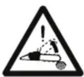
Kickback is the rapid and uncontrollable backward motion of the chainsaw in the direction of the operator. Always work in complete safety. Use chains with safety links that limit kickback.
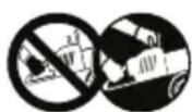
Never hold the machine with one hand! Hold the machine fast with both hands to control the machine and reduce the risk of kickback.
IMPORTANT Any damaged or illegible decals must be replaced. Order replacement decals from an Authorised Service Centre.
3.3 PRODUCT IDENTIFICATION LABEL
The product identification label provides the following data (Fig. 1):
- Sound power level
- Conformity marking
- Year of manufacture
- Type of machine
- Serial number
- Name and address of Manufacturer
- Article code
- Emission number
Write the identification data of the machine in the specific space on the label on the back of the cover page.
IMPORTANT Quote the information on the product identification label whenever you contact an Authorised Service Centre.
IMPORTANT The example of the Declaration of Conformity is provided on the last pages of the manual.
3.4 MAIN COMPONENTS
The machine is made up of the following main components (Fig. 1):
A. Engine: supplies the drive power to the cutting means.
B. Front hand grip: support hand grip located on the front of the chainsaw. This should be grasped using the left hand.
C. Rear hand grip: support hand grip located on the rear of the chainsaw. This should be grasped using the right hand. This hand grip is fitted with the main throttle controls.
D. Front hand guard: protection device seated between the front hand grip and the toothed chain, to protect the hand against injuries should it slip off the hand grip. This guard is used as a device to trigger the chain brake (par. 5.7).
E. Rear hand guard: protection device seated in the lower right section of the rear hand grip, to protect the hand from the chainsaw should it break or disconnect from the guide bar.
F. Guide bar: supports and guides the toothed chain.
G. Toothed chain: cutting element, consisting of drive links fitted with small blades called "teeth" and side connections held in place by rivets.
H. Chain restraint pin: safety device that prevents uncontrolled movements of the toothed chain should it break or slacken.
I. Spiked bumper: device installed opposite the guide bar assembly point acting as a pivot when it comes into contact with a tree or trunk.
J. Spiked bumper guard: spiked bumper cover to be fitted during handling, transportation or storage of the machine. This guard must be removed when using the machine.
K. Bar cover guard: chainsaw cover on the guide bar to be fitted during handling, transportation or storage of the machine.
4. ASSEMBLY
IMPORTANT The safety regulations to follow during machine use are described in Chapter 2. Strictly comply with these instructions to avoid serious risks or hazards.
For storage and transport purposes, some components of the machine are not installed in the factory and have to be assembled after unpacking. Follow the instructions below.
Unpacking and completing the assembly should be done on a flat and stable surface, with enough space for machine handling and its packaging, always making use of suitable equipment. Do not use the machine until all the instructions provided in the "ASSEMBLY" section have been carried out.
4.1 ASSEMBLY COMPONENTS
The packaging holds the components needed for assembly as listed in the table below:
| Description |
| Guide bar fitted with bar cover |
| Toothed chain |
| Key (housed below the lower section of the machine) (Fig. 1.M) |
| Cutting chain sharpening filing tool |
| Documentation |
4.1.1 Unpacking
-
Carefully open the packaging, paying attention not to lose components.
-
Consult the documentation in the box, including these instructions.
- Remove all the unassembled parts from the box.
- Remove the machine from the box.
- Dispose of the box and packaging in compliance with local regulations.
4.2 ASSEMBLY OF THE GUIDE BAR AND TOOTHED CHAIN
Always wear heavy duty gloves when handling the bar and chain. Mount the bar and chain very carefully so as not to impair the safety and efficiency of the machine. If in doubt, contact your dealer.
Perform all operations with the engine off.
Before assembling the bar, check that the chain brake is not engaged (par. 5.7).
- Loosen all the nuts (Fig. 3.A) and remove the clutch cover (Fig. 3.B) to get to the drive sprocket and the point where the bar is fitted.
- Remove the plastic spacer (Fig. 3.C); this spacer must be used exclusively when transporting the machine in its packaging and must not be used at any other time.
- Mount the bar (Fig. 4.A) by inserting the stud bolts (Fig. 4.B) in the groove (Fig. 4.C) and push it towards the back of the machine body.
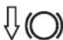
- Mount the chain (Fig. 5.A) around the drive sprocket (Fig. 5.B) and along the bar guide (Fig. 5.C), making sure it is fitted in the right direction (Fig. 5.D).
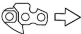
Direction in which the chain runs
If the tip of the bar is equipped with a nose sprocket, make sure the drive links are correctly inserted in the sprocket rims (Fig. 6).
- Check that chain tension adjuster pin (Fig. 7.A) is fitted properly into the hole on the bar; if it isn't, turn the chain tension adjuster screw using a screwdriver (Fig. 7.B), until the pin is completely inserted.
- Refit the guard without fully tightening the nuts.
- Turn the chain tension adjuster screw (Fig. 8.A) to achieve the desired tension.
- Raise the bar and tighten the guard nuts securely using the wrench (Fig. 9).
4.2.1 Checking the chain tension
Check the chain tension.
The tension is correct when the drive links do not slip out of the chain guides if you hold the chain in the middle of the bar (Fig. 10).
5. CONTROLS
5.1 ENGINE START/STOP SWITCH
Used to start and stop the engine (Fig. 11.C).

The engine can start and run.

The engine stops.
After pressing the stop switch, the switch automatically returns to the start position "I"
5.2 CHOKE LEVER
Used to turn on the engine when cold. The choke control has two positions:

Position A (Fig. 11.A) - the choke is not engaged (normal operations and warm start)..

Position B (Fig. 11.B) - the choke is engaged (for a cold start).
5.3 PRIMER CONTROL BUTTON
Press the rubber button of the primer (Fig. 12.A) to inject fuel into the carburettor intake manifold to facilitate startup when the engine is cold.
5.4 PRESSURE RELIEF VALVE CONTROL (FOR MODEL SP 526 ONLY)
Press the valve (Fig. 13.E) to reduce the compression of the cylinder and to start the machine more easily.
5.5 THROTTLE TRIGGER LEVER
Used to regulate the chain speed.
The throttle trigger lever (Fig. 12.B) can only be used if the throttle interlock lever is pressed simultaneously (Fig. 12.C).
The correct running speed will be achieved by pressing the throttle trigger lever (Fig. 12.B) as far as possible.
5.6 INTERLOCK LEVER
The interlock lever (Fig. 12.C) allows the throttle trigger lever to be used (Fig. 12.B).
5.7 HANDLE FOR MANUAL START
For manual engine start-up (Fig. 11.D).
5.8 CHAIN BRAKE
This is a safety braking system that blocks the chain movement when kickback occurs during cutting. Kickbacks occur following an irregular contact of the tip of the bar with a rapid upward movement of the bar that causes the hand to strike the front guard (Fig. 1.D). It must be manually released to disengage the chain brake.
Chain brake disengaged. This is achieved when the front hand guard (Fig. 1.D) is pulled all the way back towards the front hand grip until it clicks into position.

Chain brake engaged. This is achieved when the front hand guard (Fig. 1.D) is pushed all the way forward.
Do not use the machine if the chain brake does not function correctly and have it inspected by your dealer.
6. USING THE MACHINE
IMPORTANT The safety regulations to follow during machine use are described in Chapter 2. Strictly comply with these instructions to avoid serious risks or hazards.
6.1 PREPARATION
Before starting to work, it is necessary to carry out several checks and operations to ensure you can work efficiently and in maximum safety.
IMPORTANT The machine is supplied with the fuel and chain lubrication oil tanks empty.
6.1.1 Refuelling
Fill with fuel before using the machine. For preparing the mixture, refuelling methods and precautions sent see paragraph 7.3.
6.1.2 Filling with chain lubrication oil
Fill with chain lubrication oil before using the machine. For oil filling methods and precautions sent see paragraph 7.4.
6.1.3 Checking the chain tension
Perform all operations with the engine off.
Always wear heavy duty gloves.
Check the chain tension.
The tension is correct when the drive links do not slip out of the chain guides if you hold the chain in the middle of the bar (Fig. 10).
To adjust the chain tension:
- loosen the cover nuts, using the supplied wrench;
- turn the chain tension adjuster screw (Fig. 8.A) to achieve the desired tension;
- raise the bar and tighten the guard nuts securely using the wrench (Fig. 9).
Never work with the chain loose as it can be hazardous if the chain slips out of the bar guides.
IMPORTANT During the first period of use it must be checked more frequently due to settling of the chain.
6.1.4 Preparing the machine before starting work
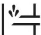
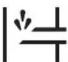
- Anti-freeze device
When using the chainsaw at temperatures under +5^ , it is necessary to change the anti-freeze device settings before starting the machine to prevent ice from forming inside the carburettor, which will result in a loss in engine power or erratic engine performance.
The machine is equipped with an air vent hatch on the cylinder lid, to allow warm air flow to the engine.
In normal operating conditions (temperatures above +5^ ), use the machine in standard operating mode, i.e. using factory default settings.
To switch from "Normal" mode to "Anti-freeze" mode (and vice versa):
- stop the machine (par. 6.6);
- remove the air filter cover and the air filter (par. 8.2);
3.a on models SP386, SP 426:
- remove the anti-freeze cap from its housing to the right of the cylinder cover (Fig. 14.A);
- Turn the anti-freeze cap so that the «SNOW» symbol is facing downwards to leave the air vent hatch open (Fig. 14.B);
3.b on models SP466, SP 526:
- unscrew the screws which secure the cylinder cover in place (Fig. 15.A) (2 screws inside and one outside) and remove the cylinder cover. (Fig. 15.B);
- remove the anti-freeze cap from its housing (Fig. 16.A), in the centre and at the back of the cylinder cover (Fig. 16.B);
- Turn the anti-freeze cap so that the «SNOW» symbol is facing downwards (Fig. 17.A) to leave the air vent hatch open (Fig. 17.B);
-
remount the cylinder cover.
-
remount the air filter cover and the relative cover (par. 8.2).
NOTE If the machine is used in anti-freeze mode at temperatures above +5^ this may cause difficulties when starting the engine and during use due to the incorrect engine speed. Always check that the machine is switched to standard mode (anti-freeze cap with the «SUN» symbol facing sideways and the air vent hatch closed) if there is no danger of ice forming.
6.2 SAFETY CHECKS
Run the following safety checks and check that the results correspond to those outlined on the tables.
Always carry out the safety checks before use.
Always carry out daily inspection before use and after dropping or other impacts to identify significant damage or defect.
6.2.1 General check
| Object Result | |
| Hand grips and guards(Fig. 1.B - 1.E) | Clean, dry, without traces of oil and grease, and fixed correctly and firmly to the machine. |
| Screws on the machine and bar | Correctly tightened (not loose) |
| Guide bar (Fig. 1.F) Properly installed. | |
| Chain (Fig. 1.G) Sharp, | not damaged or worn, mounted and tensioned correctly. |
| Air filter (Fig. 38.B) Clean | |
| Electric cables and spark plug cable | Undamaged to prevent sparks. |
| Spark plug cap(Fig. 31.A) | Undamaged and fitted correctly on the spark plug |
6.2.2 Machine operating test
| Action Result | |
| Start the machine (par. 6.3) | The chain (Fig. 1.G) must not move when the engine is running idle. △ Do not use the machine if the chain moves when the engine is running idle; in this case, contact your dealer. |
| Engage the throttle trigger lever (Fig. 12.B) and the interlock lever simultaneously (Fig. 12.C). | The levers must move freely and not be forced. The chain moves. |
| Action Result | |
| Release the throttle trigger lever (Fig. 12.B) and the interlock lever (Fig. 12.C). | The levers must return automatically and rapidly to the neutral position, the engine must return to running idle and the chain must be stationary. |
| Engage the throttle trigger lever (without pressing the interlock lever) (Fig. 12.B). | The throttle trigger lever remains blocked. |
| Press the engine start/stop switch (Fig. 11.C) | The switch must move easily from one position to another and must return automatically to the start position when released. |
| CHECKING THE CHAIN BRAKE 1. Start the machine (par. 6.3): 2. Grasp the hand grips firmly with both hands. 3. Use the throttle lever to keep the chain moving, push the front hand guard forwards using the back of your left hand; (par. 5.7). | 3. The chain must stop moving immediately. When the chain has stopped, immediately release the throttle trigger lever and disengage the chain brake (par. 5.7). |
If any of the results fails to match the instructions provided in the following table, do not use the machine! Take it to an Authorised Service Centre to be checked and repaired if necessary.
6.3 STARTUP
IMPORTANT A label (Fig. 2) is placed on the machine that summarizes the start up main steps. The label is a quick guide and it does not replace the procedures specified below.
Before starting the machine:
- Place the machine firmly on the ground.
- Remove the bar cover guard (Fig. 1.K) and the spiked bumper guard (Fig. 1.J) (if fitted).
-
Make sure the bar and the chain are not touching the ground or any other object.
-
Make sure the chain brake is engaged (par. 5.7).
IMPORTANT To avoid breaking the starter cable, do not pull the whole length of it or let it slide along the edge of the cable guide hole. Release the starter hand grip gradually, to prevent it flying back uncontrollably.
IMPORTANT Never wind the starter cable around your hand.
Never start the chainsaw by holding on to the starter cable and allowing it to fall. This is an extremely dangerous method as you lose complete control over the machine and the chain.
NOTE The switch is always in the start position (par. 5.1).
6.3.1 Startup from cold
A "cold" start of the engine means starting it after at least 5 minutes from when it was switched off or after refuelling.
- Engage the choke by turning the lever to position «B» (Fig. 11.B).
-
Press the primer device button (Fig. 12.A) 6 times to prime the carburettor.
-
For model SP 526 only: Press the pressure relief valve (Fig. 13.E).
NOTE Immediately after the engine starting, the valve automatically returns to its original position.
- Hold the machine firmly on the ground with your hand on the front hand grip and your foot in the rear hand grip, to avoid losing control during starting (Fig. 18).
If the machine is not held firmly, the force of the engine could cause the user to lose his balance or direct the bar towards him or an obstacle. - Pull the starter hand grip slowly for 10 - 15 cm until you feel some resistance, then pull it 4 times until you hear the engine start to tick over. Engine will not start at this stage.
IMPORTANT Do not pull the starter hand grip more than 4 times. -
Disengage the choke (Fig. 11.A) by turning the lever to position «A».
-
Pull the starter grip again until the engine starts as normal.
- When the engine has started, simultaneously activate the throttle trigger lever (Fig. 12.B) and the interlock lever briefly (Fig. 12.C) to cancel fast tick over. Allow the engine to run idle for 10-15 seconds.
- Disengage the chain brake (par. 5.7).
IMPORTANT Do not let the engine run at high speed with the chain brake engaged, as this could cause overheating and damage to the clutch.
10. Let the engine run idle for at least 1 minute before using the machine.
IMPORTANT If the starter hand grip is pulled repeatedly with the choke engaged, it may flood the engine and make starting difficult. " If the engine floods (see paragraph 15.5).
6.3.2 Warm start
When hot starting (immediately after stopping the engine):
- Press the primer device button (Fig. 12.A) 6 times to prime the carburettor.
- For model SP 526 only:
Press the pressure relief valve (Fig. 13.E).
NOTE Immediately after the engine starting, the valve automatically returns to its original position.
- Engage the choke (position «B» - par. 5.2) and then immediately disengage again (position «A» - par. 5.2); this will engage the fast tick over.
- Follow points 4 - 7 - 8 - 9 in the previous procedure (par. 6.3.1).
6.4 OPERATION
Before felling or delimbing for the first time, make sure:
you have been specifically trained to use this type of equipment;
- you have carefully read the safety regulations and user instructions contained in this manual;
you practise first on logs on the ground or attached to wrestles, in order to get familiar with the machine and the most suitable cutting techniques.
To operate with the machine proceed as described below:
Always disengage the chain brake, before using the throttle control.
- The machine must always be firmly held in both hands, with the left hand on the front hand grip and the right hand on the rear hand grip, even if the operator is left handed.

Stop the machine immediately if the chain stops during sawing.
6.4.1 Checks to be conducted whilst working
6.4.1.a Checking the chain tension
The chain tends to stretch gradually as you work, so you need to check its tension frequently (par. 6.1.3).
6.4.1.b Checking the oil delivery
IMPORTANT Never use the machine without lubrication! The oil tank may also be empty every time the fuel runs out. Make sure you top up the oil tank every time you refuel the machine (par. 7.4).

Make sure the bar and the chain are face when you check the oil delivery.
Start the engine (par. 6.3), keep it running at medium power and check if the chain oil is delivered as shown in (Fig. 19).
You can adjust the chain oil flow using a screwdriver on the pump adjuster screw (Fig. 20.A) which is on the bottom of the machine.
This is the symbol that identifies the oil pump regulator:
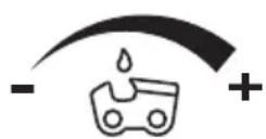
Use a screwdriver to turn it to the "+" position to increase the oil flow to the chain; turn it to the "-" position to decrease the flow.
6.4.2 Work techniques
6.4.2.a Delimbing a tree
Make sure there is nothing or anybody in the area where the branches will fall.
- Stand opposite the branch you want to cut.
- Start cutting lower branches followed by the higher ones.
- Cut downwards to prevent the bar from getting jammed (Fig. 21).
6.4.2.b Felling a tree
IMPORTANT Where two or more persons are working together on felling and bucking operations, such operations must be performed in separate areas at a distance from each other of at least 2.5 times the height of the tree being felled. Do not fell trees if this involves risks of injuring people, coming into contact with a power line or causing any form of damage. If the tree should come into contact with a main power line, report the incident immediately to the network provider.
Before commencing the felling operations:
- it is necessary to evaluate the natural inclination of the tree, the part where the branches are larger and the wind direction, to assess how the tree will actually fall;
- remove any dirt, stones, pieces of bark, nails, metal staples and wire;
- clear the area around the tree and find a stable place to stand;
- plan obstacle-free escape routes at a 45^ angle back and away from the direction of the fall (Fig. 22) which allow the operator to escape to a safe zone, approximately 2.5 times the height of the tree being felled;
- Stand upstream of the land onto which the tree will probably roll or fall over after felling
Performing a face notch
- Following the directional marks on the chainsaw (Fig. 23.A), point towards a target on the ground in the direction in which you intend to fell the tree (Fig. 23.B).
- Stand to the right of the tree, behind the chainsaw.
- Saw a horizontal face notch to 1/3 of the diameter of the tree, perpendicular to the direction in which it will fall (Fig. 24.A).
Felling back cut
- Perform the felling back cut at least 5 cm higher than the horizontal face notch (Fig. 24.B).
-
Perform the felling back cut leaving sufficient wood to act as a "hinge" (Fig. 24.C). The hinge wood will prevent the tree from twisting and falling in the wrong direction. Do not cut through the hinge.
-
Reduce the thickness of this hinge without pulling out the bar, until the tree falls.
- If there is any risk of the tree not falling in the desired direction, or that it might lose its balance moving backwards and bending the toothed chain, stop cutting before completing the felling back cut and use some wooden, plastic or aluminium wedges (Fig. 24.D) to open the cut. Force the tree to fall along the desired line by hitting the wedges with a sledge hammer.
- When the tree starts to fall, it is necessary to withdraw the machine from the cut, switch it off (par. 6.6), lie it on the ground and take the foreseen exit route. Beware of falling branches and pay attention where you put your feet.
6.4.2.c Limbing tree branches
Limbing means removing the branches from a felled tree.
Be careful of where the branches are lying on the ground, the risk of them being under tension, the direction the branch may go during cutting and the risk of the tree being unstable after the branch has been cut.
When limbing, it is necessary to leave the lower, larger branches to support the trunk on the ground. Remove the small branches with a single blow (Fig. 25.A).
It is recommended to cut the tensioned branches working from the bottom upwards to prevent the chainsaw from bending (Fig. 25.B).
6.4.2.d Bucking the trunk
Bucking means sawing a tree trunk into logs.
It is essential to make sure your feet are positioned firmly on the ground, and your weight is distributed equally on both feet. If possible, it is recommended to raise and support the trunk using branches, logs or blocks of wood.
It is easier to saw a log using the spiked bumper (Fig. 1.l):
- plant the spiked bumper into the log and use it as a pivot. Cut with an arched motion to make the bar penetrate the wood (Fig. 26);
- repeat several times if necessary, changing the point where you plant the spiked bumper.
- Trunk lying on the ground
When the entire trunk is lying on the ground, it is bucked from the top down (overbucking) (Fig. 27.A).
- Cut up to half the diameter, roll the log over and finish sawing on the other side.
- Trunk resting on one end only
When the trunk is resting on one end only:
- saw through 1/3 of the diameter from the bottom up (underbucking) (Fig. 28.A);
- then perform the final cut, overbucking to reach the first cut (Fig. 28.B).
- Trunk resting on both ends
When the trunk is resting on both ends:
- saw through 1/3 of the diameter from the top down (overbucking) (Fig. 29.A);
- then perform the final cut, underbucking the lower 2/3 to reach the first cut (Fig. 29.B).
- Sloping trunk
Always stand upstream when bucking a sloping trunk (Fig. 30).
During the operation, to maintain control when the cut is almost complete, reduce the bucking pressure without removing removing your hands from the machine hand grips. Take all necessary precautions to prevent the machine from coming into contact with the ground.
NOTE Avoid using the machine at full power for the first 6-8 working hours.
IMPORTANT Stop the machine (par.
6.6) when moving between work areas.
6.6 STOP
To stop the machine:
- Release the throttle trigger lever (Fig. 12.B) and allow the engine to run at idle speed for a few seconds.
- Turn the switch (Fig. 11.C) to the «O» position.
- Wait until the chain is stationary.
When you have reduced speed to a minimum, it will take a few seconds for the chain to stop.
The engine may be very warm immediately after it is shut off. Do not touch. The engine can cause burn injuries.
6.7 AFTER OPERATION
- Remove the spark plug cap (Fig. 31.A).
- Mount the bar cover.
- Allow the machine to cool down.
- Loosen the rod fastening nuts to reduce chain tension.
- Carefully remove any dust and debris and remove all traces of sawdust or oil deposits from the chain. (par. 7.5, par. 7.6).
- Check there are no loose or damaged components. If necessary, replace the damaged components and tighten any screws and loose bolts.
IMPORTANT Stop the machine (par.
6.6), remove the spark plug cap (Fig. 31.A) and mount the bar cover whenever the machine is unused or left unattended.
7. ROUTINE MAINTENANCE
7.1 GENERAL INFORMATION
IMPORTANT The safety regulations to follow during machine use are described in Chapter 2. Strictly comply with these instructions to avoid serious risks or hazards.

Before conducting any
inspections, cleaning or maintenance/ adjustment interventions on the machine:
- Stop the machine;
- Wait until the chain is stationary;
- Apply the bar cover, except when working directly on the chain or bar itself.
- Remove the spark plug cap (Fig. 31.A);
- Wait until the engine is sufficiently cold;
- Read the relevant instructions;
-
Use suitable clothing, protective gloves and goggles;
-
The frequency and types of maintenance are summarised in the "Maintenance Table" (see chapter 12). The table will help you maintain your machine's safety and performance. It summarises the main interventions to be made and the frequency applicable to each of them. Carry out the relevant intervention according to the first deadline.
- The use of non-genuine spare parts and attachments could adversely affect machine operation and safety. The manufacturer shall decline all liability in the event of injuries or damages caused by such parts.
-
Genuine spare parts are supplied by Authorized Service Centres and Dealers.
-
Never use the machine with worn or damaged parts. Damaged parts are to be replaced and never repaired.
IMPORTANT All the maintenance and adjustment operations not described herein must be carried out by your dealer or Authorised Service Centre.
7.2 PREPARING THE FUEL MIXTURE
This machine has a two-stroke engine which requires a mixture of petrol and lubricating oil.
IMPORTANT Using petrol alone will damage the engine and will void the warranty.
IMPORTANT Only use quality fuels and oils to maintain high performance and guarantee the duration of the mechanical parts over time.
7.2.1 Petrol characteristics
Only use unleaded petrol with an octane rating of at least 90.
IMPORTANT Unleaded petrol tends to create deposits in the container if stored for more than 2 months. Always use fresh petrol!
7.2.2 Oil characteristics
Only use top quality synthetic oil that is specifically for two-stroke engines, of JASO FC minimum specification.
Your dealer can provide you with oils which have been specifically developed for this type of engine, and which are capable of guaranteeing a high level of protection. The use of these oils makes it possible to prepare a 2.5% mixture, consisting of 1 part oil to 40 parts petrol.
7.2.3 Preparation and storage of the fuel mixture
The chart indicates the amount of petrol and oil to use to prepare the fuel mixture.
| Petrol 2-stroke | synthetic oil |
| litres litres | |
| 1 | 0.025 |
| 2 | 0.050 |
| 3 | 0.075 |
| 5 0.125 | |
| 10 0.250 |
To prepare the fuel mixture:
- Place about half the amount of petrol in a homologated tank.
- Add all the oil.
- Add the rest of the petrol.
- Close the top and shake well.
IMPORTANT The fuel mixture tends to age. Do not prepare excessive amounts of the fuel mixture to avoid the formation of deposits.
IMPORTANT Keep the petrol and fuel mixture containers separate and easily identifiable to avoid the mistake of using one in place of the other.
IMPORTANT Periodically clean the petrol and fuel mixture containers to remove any deposits.
7.3 REFUELLING
Refuelling must take place when the machine is switched off and the spark plug cap removed.
Before refuelling:
- Shake the fuel mixture container well.
- Place the machine on a flat stable surface, with the fuel tank cap facing upwards.
NOTE The following symbol is found near the fuel tank cap (Fig.32.A):
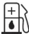
Fuel mixture tank
- Clean the fuel tank cap and the surrounding area to prevent any dirt from entering the tank during refuelling.
- Open the fuel tank cap carefully to allow the pressure inside to decrease gradually.
- Use a funnel to refill and avoid filling the tank to the brim.
NOTE When using the machine, the fuel level can be checked through the tank window (Fig. 32.B).
7.4 TOPPING UP THE CHAIN OIL TANK
NOTE The following symbol is found near the chain oil tank cap (Fig. 32.C):
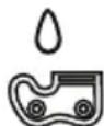
Chain oil tank
IMPORTANT Only use chainsaw oil or adhesive oil for chainsaws. Do not use oil containing impurities so as not to block the oil filter and to prevent irreparable damage to the oil pump.
It is essential that you use good quality oil to lubricate the cutting parts effectively. Used or poor quality oil does not guarantee good lubrication and reduces the working life of the chain and bar.
- It is always worth topping up the oil tank completely (using a funnel) every time you refuel. Since the oil tank capacity is enough to guarantee that the fuel runs out first, you will avoid the risk of operating the machine without lubricant.
7.5 CLEANING THE MACHINE AND THE ENGINE
After every work session, clean the machine thoroughly to remove all dust and debris.
-
To reduce fire hazards:
-
keep the machine and, in particular, the engine and muffler zone free of sawdust, branches, leaves, or excessive grease;
-
use compressed air to clean the cylinder fins on a regular basis (Fig. 33).
-
To avoid overheating and damage to the engine:
-
always keep the cooling air vent (Fig. 34) clean and free of sawdust and debris.
-
Keep the clutch bell free of sawdust and debris (Fig. 35), removing the clutch (par.
4.2) and remounting it correctly afterwards.
Have your dealer check the greasing of the internal bearing approximately every 30 hours.
7.6 CLEANING THE CHAIN
Remove any traces of sawdust or oil deposits from the chain every time it is used.
If there is excessive dirt or resin build-up, disassemble the chain and place it in a container with a specific cleanser for a few
hours. Then rinse with clean water and treat with a suitable anticorrosive spray, before reassembling on the machine.
7.7 CHAIN CATCHER
Before use, always check the condition of the chain catcher (Fig.1.H) beforehand and replace it if damaged.
7.8 NUTS AND BOLTS
- Before use, always check that all nuts and bolts are securely tightened to be sure the machine is in safe working condition.
- Before use, always check that the hand grips are firmly fastened in place.
8. EXTRAORDINARY MAINTENANCE
8.1 MACHINE AND BAR LUBRICATION HOLES
Before daily use, remove the clutch casing (par. 4.2), remove the bar and check that neither the machine lubrication (Fig. 36.A) nor the guide bar (Fig. 36.B) holes are clogged.
8.2 CLEANING THE AIR FILTER
IMPORTANT Cleaning the air filter is essential to guarantee the efficiency and durability of the machine. Do not work with a damaged filter or without a filter, as this could permanently damage the engine.
It must be cleaned after every 8-10 working hours.
Clean the filter as follows:
- Release the tab (Fig. 37.A) and remove the cover (Fig. 37.B).
- Press the metal air filter block until it attaches with a click (Fig. 38.A).
- Remove the air filter (Fig. 38.B), tap it gently to remove the dirt and clean using a soft brush.
- If the filter is completely clogged, wash with clean petrol. If you are using compressed air, aim the jet so that it blows from the inside towards the outside (Fig. 39.A).
- Replace the filter (Fig. 40.B), pull the metal block (Fig. 40.A) until it clicks the filter into position.
- Remount the casing (Fig. 41.A) making sure that all the parts are
positioned correctly in their housings on the cylinder cover (Fig. 41.B).
- Insert the lower section of the tab and press the top part until it clicks into place (Fig. 41.C).
8.3 CLUTCH HOUSING
Have your dealer check the condition of the metal band around the clutch housing once a month. The band must be replaced if deteriorated or deformed.
8.4 CHAIN DRIVE SPROCKET
Regularly check the condition of the sprocket with your local dealer or Authorised Service Centre and replace it when wear exceeds the accepted limits.
Do not mount a new chain with a worn sprocket or vice-versa.
8.5 CHECKING THE SPARK PLUG
The spark plug (Fig. 31.A) can be accessed by removing the air filter cover (Fig. 37.B).
Periodically remove and clean the spark plug using a metal brush to get rid of any deposits (Fig. 42.A).
Check and reset the correct distance between the electrodes (Fig. 42.B).
Replace the spark plug and fasten it firmly using the supplied wrench.
The spark plug must be replaced with one with the same characteristics whenever the electrodes have burnt or the insulation has worn, and in any case every 100 working hours.
8.6 STARTER CABLE
The starter rope must be replaced by your Dealer or Authorised Service Centre as soon as it shows signs of wear.
8.7 MAINTENANCE OF THE TOOTHED CHAIN
To ensure that the chainsaw works safely and efficiently, it is essential that the cutting means are well-sharpened.
Chain sharpening is necessary when:
- the sawdust looks like dust.
-
cutting becomes more difficult.
-
the cut is not straight.
- vibrations increase.
- fuel consumption increases.
Kickback may occur if the chain is not sufficiently sharpened
IMPORTANT It is recommended to have a specialised centre sharpen the chain using the right tools to ensure minimum removal of material and even sharpness on all the cutting edges.
8.7.1 Chain sharpening
If you sharpen the chain yourself, use special round-section files with the right diameter depending on the type of chain (see "Chain Maintenance Table", chap. 14). You need a certain amount of skill and experience to avoid damaging the cutting edges.
Sharpen the chain as follows:
- Stop the machine (par. 6.6).
- Disengage the chain brake (par. 5.7) (
- Secure the bar with the chain in a vice (Fig. 43.A), so that the chain can run smoothly.
- Tighten the chain if it is loose (par. 6.1.3).
- Insert the file in the tooth at a constant angle from the cutting edge (Fig. 43.B). Using a sharpening plate makes using the file easier (Fig. 43.C).
- Sharpen in a forward motion a few times and repeat this on all the cutting edges facing the same way (right or left).
- Turn the bar over in the vice and repeat on all the other cutting edges.
- Check that the limiter tooth (Fig. 43.D) complies with the levels indicated in the "Chain Maintenance Table" (chap. 14) and file any projecting parts with a flat file, rounding off the edge.
- After sharpening, remove all traces of filing and dust and lubricate the chain in an oil bath.
8.7.2 Replacing the toothed chain
Replace the chain when:
the length of the cutting edges reduces to 5mm or less (Fig. 43.E);
- there is too much play between the links and the rivets.
- the cutting speed is too slow and the repeated sharpening does not improve the cutting speed. The chain is worn.
IMPORTANT After replacing the chain, its tension level must be checked more frequently due to settling of the chain.
8.8 GUIDE BAR MAINTENANCE
NOTE Any work on the guide bar requires specific experience and special tools in order to achieve top workmanship standards; for safety purposes, we recommend you contact your dealer to ensure work is done correctly.
To avoid asymmetrical wear on the bar, make sure it is turned over periodically.
To keep the bar in perfect working order, proceed as follows:
- Grease the bearings on the nose sprocket (if present) with the syringe (not included).
- Clean the bar groove with the scraper (not included) (Fig. 44.A);
- Clean the lubrication holes (Fig. 44.B);
- With a flat file (not included), remove burn from the edges and level off the guides.
8.8.1 Replacing the bar
Replace the bar whenever:
- the groove is not as deep as the height of the drive links (which must never touch the bottom);
the inside of the guide is worn enough to make the chain lean to one side.
8.9 TUNING MINIMUM SPEED
If the cutting means moves when the engine is running idle, contact your dealer or Authorised Service Centre to have the engine adjusted correctly (par. 8.11).
8.10 TUNING THE CARBURETTOR
The carburettor is tuned by the manufacturer to achieve maximum performance in all situations, with a minimum emission of toxic gas in compliance with the regulations in force.
In the event of poor performance, contact your Dealer or Authorised Service Centre for a check of the carburetion and engine.
Carburettor tuning:
T = minimum speed tuning
L = low speed mixture tuning
H = high speed mixture tuning
9. STORING THE MACHINE
IMPORTANT The safety regulations to follow for putting into storage are described in paragraph 2.4. Strictly comply with these instructions to avoid serious risks or hazards.
If you are not going to use the machine for a period of more than 2-3 months, we recommend you do a few things before putting it away. This will make it easier when you want to use the machine again and will also prevent permanent damage to the engine.
Before putting the machine away:
-
Unscrew the two clutch housing nuts, remove the housing and remove the chain and bar.
-
Empty the oil tank, fill with about 100-120 cc of specific liquid detergent and plug the cap.
-
Fit the guard back on without tightening the nuts.
-
Start the engine and keep it running until all detergent is used.
-
Start the engine and run it idle until it uses up all the fuel that is left in the tank and the carburettor.
-
Wait for the engine to cool.
-
Remove the spark plug.
-
Pour a teaspoon of (new) 2-stroke engine oil into the spark plug slot.
-
Pull the starter hand grip several times to deliver oil to the cylinder.
-
Replace the spark plug with the piston in the dead end upper position (visible from the spark plug slot when the piston is at maximum stroke).
-
Clean the machine thoroughly.
-
Check the machine for any damage. If necessary, contact the Authorised Service Centre.
-
Store the machine:
- in a dry place
- protected from inclement weather
- with the bar cover guard fitted correctly
- in a place where children cannot get to it
- making sure that keys or tools used for maintenance are removed.
Before starting to use the machine again:
- Remove the spark plug.
- Pull the starter hand grip a few times to eliminate excess oil.
- Check the spark plug (par. 8.5).
- Arrange the machine (par. 4.2 chap. 6)
10. HANDLING AND TRANSPORTATION
When handling or transporting the machine, always:
stop the machine (par. 6.6).
- wait until the chain is stationary.
- remove the spark plug cap (Fig. 31.A).
- mount the bar cover.
- only hold the machine using the hand grips and position the bar in the opposite direction to that used during operation.
When transporting the machine on a vehicle, always:
- position it so that it does not cause a hazard to anyone;
- fasten firmly to the means of transport using ropes or chains to prevent it from tipping over causing damage and fuel leaks.
11. ASSISTANCE AND REPAIRS
This manual provides all the necessary information to run the machine and for correct basic maintenance operations which can be performed by the user. Any regulations and maintenance operations not described herein must be carried out by your Dealer or Authorized Service Centre, which have the necessary knowledge and equipment to ensure that the work is carried out correctly, maintaining the correct degree of safety and the original operating conditions of the machine. Any operations performed in unauthorized centres or by unqualified persons will invalidate the Warranty and all obligations and responsibilities of the Manufacturer.
Only authorized service centres or dealers can carry out guaranteed repairs and maintenance.
- The authorized service centres or dealers only use genuine spare parts. Genuine spare parts and attachments have been designed specifically for machines.
- Non-genuine spare parts and attachments are not approved. Use of non-genuine spare parts and attachments cause the warranty to be invalidated.
- It is advisable to send your machine once a year to an authorized service centre or dealer for servicing, assistance and safety device inspection.
12. WARRANTY COVERAGE
The warranty covers all material and manufacturing defects. The user must
follow all the instructions provided in the accompanying documentation. The warranty does not cover damages caused by:
- Failure to become familiar with the documentation accompanying the machine.
- Carelessness.
Incorrect or prohibited use or assembly. - Use of non-genuine spare parts.
- Use of attachments not supplied or approved by the manufacturer.
The warranty does not cover:
- Normal wear and tear of consumables, such as cutting means, safety bolts.
Normal wear and tear.
The purchaser is protected by his or her own national legislation. The purchaser's rights under the national laws or his or her own country are not in any way restricted by this warranty.
13. MAINTENANCE TABLE
| Intervention Frequency Paragraph | |||
| First time | An then after | ||
| MACHINE | |||
| Check all fasteners | - Before | each use 7.8 | |
| Safety checks/check controls | - Before | each use 6.2 | |
| Check the chain catcher | - Before | each use 7.7 | |
| Check the machine and bar lubrication holes | - Before | each daily use 8.1 | |
| General cleaning and inspection | - After each | each use 7.5 | |
| Cleaning the chain | - After each | each use 7.6 | |
| Clutch housing bearing greasing | - 30 hours 7.5* | ||
| Check the clutch housing | - Once a month 8.3* | ||
| Check the chain drive sprocket | - Once a month 8.4* | ||
| Chain maintenance | - | - | 8.7, 14 |
| Bar maintenance | - | - | 8.8 |
| ENGINE | |||
| Checking/topping up fuel level | - Before | each use 7.3. | |
| Topping up the chain oil level | - | Whenever refuelling | 7.4. |
| General cleaning and inspection | - After each use 7.5 | ||
| Cleaning the air filter | 8-10 hours / every season | 8.2 | |
| Cleaning the spark plug | - 10 hours / every season | 8.5 | |
| Replace spark plug | - | 100 hours / every season | 8.5 |
- The operation must be carried out by your Dealer or a Authorised Service Centre
14. CHAIN MAINTENANCE TABLE
| Chain pitch | Limiter tooth level (a) File diameter (d) | |||
| a | d | |||
| inches mm | inches mm inches mm | |||
| 3/8 Mini | 9.32 | 0.018 0.45 5/32 4.0 | ||
| 0.325 | 8.25 | 0.026 0.65 3/16 4.8 | ||
| 3/8 | 9.32 | 0.026 0.65 1/3/64 5.2 | ||
| 0.404 | 10.26 | 0.031 0.80 7/32 5.6 | ||
This table gives the sharpening data for different types of chains, but this does not mean you can use chains other than
those approved and listed in the "Correct bar and chain combination table".
15. PROBLEM IDENTIFICATION
| PROBLEM PROBABLE CAUSE REMEDY | ||
| 1. The engine will not start or will not keep running | Incorrect starting procedure. Follow the instructions (par. 6.3) | |
| Dirty spark plug or incorrect distance between the electrodes | Check the spark plug (par. 8.5). | |
| Air filter clogged Clean and/or replace the filter (par. 8.2). | ||
| Anti-freeze device assembled incorrectly | Check the assembly position (par. 6.1.4) | |
| Carburetion problems Contact the Authorised Service Centre or dealer.. | ||
| 2. The engine starts but lacks power. | Air filter clogged Clean and/or replace the filter (par. 8.2). | |
| Carburetion problems Contact the Authorised Service Centre or dealer. | ||
| 3. The engine runs irregularly and lacks power when revved | Dirty spark plug or incorrect distance between the electrodes | Check the spark plug (par. 8.5). |
| Bar and chain problems Check that the chain runs freely and the bar guides are not deformed. | ||
| Carburetion problems Contact the Authorised Service Centre or dealer. | ||
| 4. The engine makes too much smoke | Incorrect composition of the fuel mixture | Prepare the fuel mixture according to the instructions (par. 7.2) |
| Carburetion problems Contact the Authorised Service Centre or dealer. | ||
| 5. If the engine floods | The starter grip has been driven repeatedly with the choke engaged. | Remove the spark plug (par. 8.5) and gently pull the starter rope hand grip (Fig. 11.D) to eliminate any excess fuel; then dry the spark plug electrodes and remount it on the engine. |
| 6. No oil is released | Poor quality oil When the engine is cold, empty the tank, clean it and the pipes with liquid detergent and change the oil. | |
| Lubrication holes are clogged Clean them (chap. 8.1) | ||
| 7. The chain moves when the engine is running idle | Incorrect adjustment of fuelling | Contact the Authorised Service Centre or dealer. |
| 8. The machine starts to vibrate abnormally | Damaged or loose parts. Stop the machine and disconnect the spark plug cable (Fig. 31.A).Inspect for damage. Check and tighten any loose parts. Have all checks, repair work and replacements carried out by an Authorised Service Centre or dealer only. | |
| 9. The machine has struck a foreign body. | Damaged or loose parts. Stop the machine and disconnect the spark plug cable (Fig. 31.A).Inspect for damage. Check and tighten any loose parts. Have all checks, repair work and replacements carried out by an Authorised Service Centre or dealer only. | |
If problems persist after having performed the above operations, contact your dealer or an Authorised Service Centre.
16. ACCESSORIES
The "Correct bar and chain combination table" contains a list of all possible combinations between bar and chain, indicating those which may be used on each machine, marked with the symbol "√".
The same table also provides the specification data for all chains and bars approved for use on each machine.
Only use the replacement bars and chains listed in the table. The use of unapproved combinations may be hazardous and cause serious injuries to operators and damage the machine.
In consideration that the selection, application and use of the bar and chain are actions made solely by the user, at his own discretion, the latter assumes responsibility for damages of any kind arising from such actions. When in doubt or if lacking knowledge of the specifics
of each bar or chain, contact your dealer or Authorised Service Centre.
INDICE
- INFORMACION GENERAL 1
- NORMAS DE SEGURIDAD 2
- CONOCER LA MAQUINA 4
1.1 KUIDAS KASUTUSJUHENDIT LUGEDA
Pannarette paksud tookindad;
8.8 SAEPLAADI HOOLDUS
7.2 POLTTOAINSEOKSEN VALMISTUS
5.7 POIGNEE DE DEMARRAGE MANUEL
10. MANUTENTION ET TRANSPORT
8.3 SANKABOS VARPELIS
2.3 BO TEKOT HA PABOTATA
06nap3a pa6ota
He naIeTe ro MOTopoT BO 3aTBopeH npocTo pKe MoKe Da ce co6epaT onacn jaIepoM MOHcNdHrACOBn. OnerpaunTe 3a nalebe Tpe6a Da ce H3BeDaT Ha OTBopeHo HIn BO npocTo KoJTo do6po Ce npoBeTpBya. 3anomHeTe DeKa N3dyBHnTe rAcOBn Ce OTPBHN.
Kora ja naIInTe MaunHaTa, He HacOuyBajTe ro npDyUyBaOT, a CO Toa Nn3dYbHInTe racoBN KOH 3anaJIbN MaTePnn.
He KopncTeTe ja MaunHaTa BO cpeDnHa KaDe NoCTOn p3Nk Od eKcnIoo3nJa, BO npCycTBo Ha 3aNaJINbMaTePnn, racOBn nn HeuNcTOnJa. EJeKtpnHnTe KOHTaKTn nn MExaHnKnTe DeJIobN MoKe Da rHeepnPaat NCKpn KOn MOKe Da n 3aNaJat npabOT nn NcnapyBaHaTa.
Pa6oTeTe cAmO Ha dHeBHa CBETJInHa nn np Do6po BeWtauKo OCBetJIeHne n np ycIOBn Ha do6pa BnDInBOCT.
- OndaJeTe Tn IucaTa, Deuata N KINBOTHTe OD oblaCTa 3a pa6Ota. HeonxOJHo e deuata Da 6uDat noi HaI3Op Ha dpyro Bo3pacHo Iuie.
- Поверете далдугллца ce haoraat Hajmaлку ha 15metpn Odaileyehoct od oncerot ha pa60Ta ha MaunHaT;
-ИзберHyBaJTe KOra e MoKHoДа pa60TnTe Ha MOKapи IIN3rAB TepeH INIHa TepeH N KOI CE MHORY HepaMHN INI3aKOCEH N He rapaHTnpaAT Cta6HIOCT Ha KopncHNKOT npi pa6Otata;
- O6pHeTe ocObeHO BHNMaHne Ha
HepaMHnHnTe Ha TepeHOT (rpyTKn, KaHaJI), 3aKocyBaHbTa, cOKPneHn ONaCHOCTN Hn Ha npCycTBOTO Ha daJeHH OnaCHOCTN KOnIHTo MoKe Da ja nonpeuAT BnDInBOCTa.
- O6pHeTe OcO6eHO BHNMaHne BO npncycTBO Ha cTpmHHn, DynKn nn npenpeKn.
BHHMabajte Ha coo6paKaJOT Kora MaunHaTaCe KopnCTN BO 6Jn3nHa Ha nT.
3a da ce n36erhe pniKOT oN INHcndeHTN, He octabajte ja MaunHaTa co TOnoI MOTOP BO JnCja N CeueHa TpeBa, INn Mey dpyrN 3anaJIbN MaTepnJaIN.
OndecyBaHe
Bo TeKOT Ha pa6oTaT, MaunHata ceKOraMopa Da ce DpKn UBPCTO Co DBeTe paue (Co Toa wTo JEBaTpaKa e NocTabeHa Ha npEHNOT paKOpat, a DeChATA Ha 3aDHNOT He3ABNCHO daIII ONepaTOPOT eJeByap IIN DECHNAP) n OdaJIeKy od TEJOTO..
3a3eMeTe UBpCTa No3njuJa OdpKByBaJTe BHNMaTeJeH npCTan.
- N36erHyBaJTe KOpNCTeHe Ha cKaIIHa nn Hecta6nHn PnlaTΦopMn.
- I36erHyBajTe da pa6oTnte camn nnn ceIocHO n3OJIpaHn 3a da MOKe da no6apate nomou BO cnuyaj Ha nHcndENT.
- Hinkoraaw He TpuaTe, TyKy OndeTe.
- ObpheTe BnHMaHne Da He yDnpaTe CnIHO BO CTpaHn TeLa/npeHu Co IIOCTOT 3apaN MoJHa npoeKuJa Ha CTpyrotHn Npei3BnKaHn OD OWTeYBaHe Ha CnHnIpOT. Ako loCTOT ydpn BO npeUka, moKe da npeI3BnKa KOHTpaydap. NobpaTeyap Ce Do6bNA Kora KpajHnTe ToKn Ha CnHnIpOT ce cydpYbaaT CO npEmdet nI KORA DpBOTo rO npITnCKa nIbOKnpa CnHnIpOT npi CeueHe. OBoj KOHTaKT Ha KpajHnTe DeIOBn Ha CnHnIpOT MOKe Da npeI3BnKa MHORY 6p30 OTCKOHyBaHe BO pa3HN Ipabu, ByTkajKn rO BoDeuKNOT LOCT HArOpE IN KOH KopCHNKOT, a Toa ce CnyuBA Kora CnHnIpOT ce 6Loknpa DOJIkppeHnOT DeHn Ha IOCTOT. Bo obata clyaja, npOTNbApot MOKe Da npeI3BnKa r6be He kHTpoJa Bp3 MOTOpHaTa PIIa co MOnHH TeuKn NocLeDiuN. 3a da n36erHeTe npOTNbAp, npEzMeTe rN CLeDNITE ODpeHn MEPn Ha npETna3INBOCT:
-Држete ja плataцвсTo, co палцte
и постпго Okoly paчкпге на плata co
синцп и CTавajkn Ги телоти рацетe
ВО позида К joа ВИdo3BOЛУВа ду
издржтse удapнTe Ha npOTnBydapOT.
-He npkTe rna paTe MhOry daIeKu n He ceYeHaBnBcHnHaTa Ha pameHnnte.
- Kopnctete rN BODINKHTe Ha loCTOT n CnHnIpOT cmo 3a pa6To wTO rN NOCOuI pOn3BODNTeIOT.
- Pnpdpkybajte ce do ynaTCTBaTa Ha npOn3BOJNTeIOT BO ODHOC Ha OCTpeHBeTO I ODpKByBaHBeTo Ha NIIaTa CO CINHIpOT.
- I36erHyBaJTe n3IoKyBaHBe Ha npaunHa HnHa nnIeBnHa 1TO rN pOn3BcYBa CnHpnpOT npn CeYeHeTo.
He donnpajte rH deJIOBHTe Ha MOTOPOT uTO ce 3arpeBaat BO TEKOT Ha pa6oTata. Pn3NK OJ ONEKOTHHN.
Bo clyuj ha deeEHT nHn HnUeHTN BO TEKOT Ha pa6oTaT, BeDnaW NcKnyeTe rO MOTOP T OndaJeTe ja MaunHaTa BHNMaBajKn Da He npedn3BnKaTe dpyrN OwTeTyBaHa. Bo clyuj Ha nHUndENT co LInuHa NobpeDa nn NobpeDa Ha TpeTo Lnue, PnCTanete BeDnaw KOH NOCTaNKaTa 3a DaBaHe HajcooDbETHa npBa NOMO 3a DaDeHaTa COcToj6a N ObpaTeTe ce BO COoDBetEn UeHTap 3a 3dpabCTBeHa 3aWHTTa 3a HeONXODHO JeKyBaHe. OTCTpaHete Rn TEMELINO CITE OCTaTOU ON KOCeHbTO
ITOMOKe Da npedn3BnKaaT DeΦeHT NINIOBpeNHa Nua HIN JINBOTHn aHO OCTaHaT He3a6eJHaHO BO MaunHaTa.
- pOdoJxHa n3IOxHeocT Ha Bn6paun MoJc Da npEni3BnHa noBpeu H HeBPOBaCKyIapHn NopemetyBaHa (no3HaTu KaKo "PejHOOB CnHDPOM" nn "6eJa paKa") ocObEHO Kaj OHne 7TO ce n3IOxHeH Ha cnpKylapHn BnJaHnja. CmMTomnte MoJc Da ce nokaHaT ha paTe, Ha paHNte 3rIoobOn Hn Ha npCTHe I Ce MaHnΦeCTnPaat Co rSyBe Ha OCET, BkOuaHEToCt, YeShaHe, BoNka, Obe36oJyBaHb E n CTpyKtypaJIHn IpOMEHn Ha KOJaTa. ObNe eFeHTn MoJc Da ce 3rOleMaT co HnCKn HaDBOpeuHn TempeaTpyn / nn Od npekUmepeH npNTOCK Bp3 paKHTe. Ppi nojaba Ha OBne CmIMTOMn, Tpe6a da Ro HamaJIte BpEmeTO Ha KOpNCTeHb Ha MaUnHaTa I Da CE COBeTyBaTe CO Jekap.
OrpaHcyBaBe npynoTe6a
MaunhaTHe Tpe6a Da ja KOpncTaT Iuca uTo He Ce BO COcTO6a Da ja dpXHaT UBPCTO co oBeTe paue N/INn Da ODPKyBaat Cta6nHa pamHOTeka Ha HO3eTe BO TEKOT Ha pa6oTaT.
- Hnkoraa He KopncTeTe ja MaunHaTa co OwTeTeHa 3aWHTa, aKO HeOCTacyBa IIN aKO He npabuHIO NOCTaBeHa.
He KopncteJa MaunHaTa aHOnOJIHnTeJHaTa/NOMoJHaTa ONpeMa He Ce NocTabeHn Ha daJeHnTe ToKn.
He ncknybajTe,Je3aKTHBnpajTe, BaTe T MaHometapOT 6e36eHOCHTe CNTEM/MNKpOppeKNHyBaun.
He meHyBaJTe rnpereylaucnTe Ha MToPOT H He DoBeDyBaJTe FO MOTOPOT BO RoIem peKIM Ha pa6Ota.AKO MOTOPOT NoYHe da pa6Otn CO npekymepen 6pOj Ha BpTeHN, Pn3NkOT OJ LInHn NOBpeDi Ce 3rOJIeMyBa.
He n3IoxyBajTe ja MaunHaTa Ha HeNoTpe6Hn CInn Hne KopncTeMe Mala MaunHa 3a N3BeDyBaHbe TeuKn pa60Tu; aEKBaTHO KopncTeHb Ha MaunHaTa rHaMaJyBa pN3NKOT rTo Noo6pyBa KBAJIHTeTOHa pa60TaTa.
2.4 ODPKHYBAHbE,ODIOHOYBAHbE
PeIOBHO ODPKHyBajTe n npaBnHObOdIOKeTe ja MaunHaTa 3a da ja ODPKHTe 6e36eHocTa Ha MaunHaTa N HbOTo Ha pa60Ta.
OdpkyBaHe
3a da ro HamaJIte pN3IKOT od noKap, peoBHO npOBepyBajTe daIIMa npOleaho MacNo IINI rOpIBO.
- DaeHte HnBOa 3a 6yaba N Bnbaqun BO OBA yNaTCTBO CE MaKcImaJIHb BpeHocTN npN yNoTpe6a Ha MaunHaTa. YnOte6ata Ha eJeMeHT 3a KoceHe KOjTuTo He e CtaBnIeH, DnHexeHbeto Co npeRoiMea 6p3nHa, HeoPxyBaHbeto Ha MaunHaTa, 3HaHTeJHO BInJaat Bp3 emncjata Ha 6yaba nn Bnbaqun. 3aToa, HeonxOJHo e Da npImeHyBaTe 3aHTHTM MeKn 3a Da eJIMmHnpaTe MOHN OwTeTyBaHa 3apAn 3roJeMa 6yaba nn 3HaunTeJIN Bnbaqun. PeOBHO oDpKvBajTe ja MaunHaTa, HocTe CnyaJIKN IpOTNb 6yaba n npabete Na3N BO pa60TaTa.
Ondarabe
- HnKoraw He yuBajTe ja MaunHaTa Co roPnBO Bo pe3epBoaPot BO npocTopnJa KaDe nCnapyBaHbata OJ rOpNBOTo MOKe Da dOpnat Do OTBopen PImaMeH, NCKpa NIN Do N3BOP Ha TOnnHa.
3a HamaJyBaHbe Ha pN3IKOT OD OraH, He OCTaBajTe NOIHN KOHTejHepn BO 3aTbOpEn npocToP.
2.5 3AHTNTA HA JHBOTHATA CPEINHA
3aHTaHa JNBOHTa CpeHnA Tpe6a Da ce n3BpyBa peJeBaHTHO I npOpTeTHO pni yNotpe6a Ha MaunHaTa BO KOpCT Ha rpaHaCnTe NOroHocTn HA IpocTopoT Bo Koj KInBeeme.
- H36erHybajTe nojaba Ha eIemEnTHuTo ro hapuybaaT HenocpeHOTO onkpykaBahe. KopncTeTe ja MaunHaTa cAmo BO pa3ymHO Bpeme (He MHORY paHo HayTPO IdoUHa Habeuep Kora MoKe da rN BO3HemnPte lyfTeTo).
Bo TeKOT Ha pa6oTaT a Do oDpeDeHOpacnpcKyBaHe Ha MacIoTO Bo CpeDInHaTa, KOe NaK e HeONXoDHO 3a NODMaCyBaHe Ha CINuPoT. 3apaN ToA, KopncTeTe cAmO 6bnapa3rpaIINbMacJa, CneuΦnHn 3a BaKBO KopncTeHe. Ynotpe6aTa Ha MINhepaJIHO Maclo Hn MOTOPHO Maclo PpeDn3BnkyBa TeShKn UTeTn Ha OKoJInHaTa. -
DocneHcIeTe rJIOkaJIHnTe 3aKOHn 3aΦpIaHe Ha aM6aJaKaTa, MacIaTa, RopNBOTo, aKymlaTopOT, ΦNITPte, DeIOBn BO paCnaIarHe NII KAKBn 6bIIO eIeMeHTn CO WTeTHO BInjaHne BP3 JINBOThaTcpeDHa. Obne OTpaOn He cMee Da ceΦpIaaT BO ry6pe TykTupe6a Da ce CeJIeKtnpaat N ODNecAT BO COODBeTHn CObnpHn CENTPN KOn peuKlnpaat MaTepnJaJI.
CleTe rN BO ueIOCT loKaHInTe 3aKoHn 3a φpIaHbe Ha MaTepnJaIInTe ITO ce pe3yIITaT Ha CeyeHeTo. -
Pn nCΦpIaHe oD yNoTpe6a, He ocTabajTe ja MaunHaTa KaDe 6HNO BO npnpOdaTa, TyKny pPeajTe ja BO CObIpen ueHTap BO corlaacHOCT CoBaKeHNTe IOKaJIH N3aKOH.
3. 3ANO3HAJTE JA MALINHATA
3.1 ONHC HA MAUHATA N IPEBUNDEHA YNOTPEBA
Obaa MaunHa e yumckn ypei nn notoHOMOTOPHa Nila co CnHpI TO ce HanojyBa Co6aTepnja Ie HameHeTa 3a pa60Ta BO Wyma.
MaunhaTa ce COCTO ON dBOTaKTeH MOTOP CO BHaTpeUHO COROpYBaHe, CE HANOjyBa CO MeuABnHa Od MaCNo N 6eH3nH KoJaWTO Ce IaN CO BO3DyX NIOCT 3a HabeDuBaHe KOJwTO CnyKn Da rno PpeHecyBa DBNKeHbETo Ha MOTOPBp3 CNHUnPOT CO 3aIqN 3a IpaBnH0 N TOHOCeYeBe. DBnKeHbETo Ha MOTOP Co CnHmnp Ce PpeHecyBa PpeHy φprKzjuHa ueHTpnФyraJIHa Maca n PpeDn3BnKyBa DBNKeHbE Ha CnHUnPOT KOra MOTOPe Ha MInHMym.
OnepaTopoJ aDpHn MaunHaTa co DBeTe paCe 3a npedHaTaN3aHaTpaayKa n rnaHTNBnpa TlABHNTe KOMaHn ODPKByBajKn cekoraaw 6e36eNo pactoJahne oD ypeDT CO CEuHBOTO.
3.1.1 IpeBnEHa ynoTpe6a
ObaMaunHa e npoeKtnpaHa n KOHcTpynpaHa 3a:
-cobopyBaHbe,ceHebe nKacTpeHbe Ha dpBja CO dImeH3nI ITO ce DaJeHN NO DOJIKNHa Ta Ha loCTOT 3a HabeDyBaHbe NII DpBeHN PpeMeTN Co aHaONrN KapaKTepNCtIKN.
- Camo e deh onepaTop moHe da ja KopnCTn.
3.1.2 HecooDbetHa ynoTpe6a
Koja n da e dpyra ynoTpe6a,nonHaBb oD ropeHabeDeHnte,MOKe Da npetCTabyBa onaCHOCT n da npedn3Bnka NOBpeN uWTeTN 3a Iuca H/nnn PpeMeTu. Ce otpplaaT npn He npabnHa ynoTpe6a (kako npimep, Ho He ce orpaHnUyBa Ha cneHOTO):
-perylaunjaHaKnBa orpada,
-06lnkyBaHBe,
-ceKaHBe rpaHKn, caHaun npBHe n ambaJn Od ceKaKOB BnD,
-ceheMe6eI HnIuTo 6HIO dpyo
UTo COdpKn KInHn, UpaΦOBn n CeKoj
Dpyr BnHa MeTaJHn KOMNoHEHTN,
-Mecapcn pa60TN,
-ynotpe6aHaMaunHaTa3aceHeMeMATEpJaJI KOnUTo He Ce Od npBO (nlaCTnKa, rpaedJeH MaTEpJaJI),
-ynoTpe6aHaMaunHaTa KaKOpaYka 3a NODnHyBaHbe, CnyuTaNBeIIN KpWeHBe PpeMeTN,
- ynoTpe6a Ha MaunHaTa Kora e 6JIOKupaHa Bp3 qHKcha Notnopa.
- ynoTpe6a Ha ypei n co ceuBa wTo He Ce HabeDeHn BO TaBeJaTa "TexHnUKn POnaToU". OnaHocT oCepNo3HN Nobpei N OwTeTyBaHa.
-ynoTpe6aHaMaunHaTaOCTpaHaHa NOBeKe lyre.
BAHHO HecooDbetHaTa ynoTpe6a Ha MaunHaTa DOBeyBa Do OTpPaHbe Ha rapaunjata na ja OTpPcA cekoja OroBOPHOCT Ha npOn3BOdnteIOT, ppePpLyBajn rHa KOpncnKOT pOn3Je3eHnte OBpcnnpEn3BnKaHn OD NobpeDn Nn OwTeTyBaHaTa LNHyHO nn Ha TpeTn Nla.
3.1.3 Bua Ha KopncnK
Obaa MaunHa e HameHeTa da ja KaOpNCTaT KOpNCnU, T.e. OepaTopu KOnuTo He ce npopecnoHaJIu. HameHeta e 3a "DomauHa ynotpe6a".
3.2 O3HAKN 3A B6E3BEdHOCT
Ha MaunhaTa HMa Cm60JN (cI.).2).HnBnata 3aJa a e da ro notcetyBaat onepaTopoT Ha NOCTaKNTe WTo Tpe6a Da rN cJeDN BHNMaTeJHO n CO 3aDOJIKNTeJHm MepKn 3a npETna3JIbOCT.
3HaueHe Ha cM60JIte:

BHIMAHHE! ONACHOCT!
ObaMaHHa MoKe Da 6nDe onaCha 3a Bac nnn 3a dpYrTe DOKoNky He ce Kopncn npabnlo.

BHIMAHNE!PpeIa ja KOpNCTnte ObaaMaunHa, npOHTajTe royNaTCTBOTO 3a yNoTpe6a.

KopncnKOT Koje OndroBopeH 3a OBaa MaunHa, npc CeKoJdHeBHO KOHTHynpaHO KopncTeBe BO HopMaJIH NycOBN, MOKe Da 6nDE n3LoXeH Ha 6yKa eHaKBA Hn NorOleMa oD 85 dB (A). KopncTeTe aKcyCTnUka 3aWTNTa N 3aWTNTa 3a OHTe IN CTabajTe WJEM 3a 3aWTNTa.

HocTe paKaBnI 3aHTnTHN YeBIn!

ONACHOCT OJ KOHTPAYDAP!
KoHTpaydapOT npeIN3BnkyBa
HeHaJeJHO DnIKeHBe 6e3
KOHTpOJa Bp3 MOTOpHaTa
Pnla KOH ONepaTopOT.
Cekoraw pa6oTe 6e36eHNo.
KopncTeTe CnHnp co
6e36eHocn 3aIcN wTO ro
NonpeCyBaAT KOHTpaydapOT.
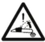
He KopncTeTe HNKoraaw ja MaunHaTa co eHa paKa! DpKeTe ja cBpCTo MaunHaTa co dBete paue 3a da hMaTe KOHTpola Bp3 Hea I Da rO HaMaJIte pN3IKOT Od KOHTpaydap.
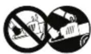
BAHHO DaenHeTe eTKeTu wTO ce cHnHaJe nn He Ce YITnBn, TpeBa Da Ce 3aMeHaT. NobapajTe HOBeTKeTu oD COoBBeTeH ueTp nn OJ OBnacteHOT cepBncep.
3.3 ETNHETA 3A INDEHTNΦHACUJA HA IPOH3BOJOT
ETnKeTaTa 3a nDeHTnФnKaunJa Ha npOn3BODOT rN COdpHn CneDnTe NoadToCu (cI.1):
- HnBO Ha aKcTmHa MoHocT
- O3HaKa 3a yCorlaCeHoCT
3.ФОДИHAHa npOIN3BOIDCTBO - TnHa MaunHa
- Cepinckn 6poj
- Ime n apeca ha npoH3BOdnteIOT
- HoD Ha npOn3BOd
8.БpojHa emncn
3aHWeTe rN noDaToUHe 3a
HDeHTnΦnKaunja 3a MaunHaTa Ha
COoBBeTHnTe MeCTa Ha daEHaTa etHKeTa
OD BHaTpeuHaTa CTpaHa Ha KaNaKOT.
BAHHO Hopnctete rna daennte noaTOU 3a ndeHTnphiauja cekojnat Kora KOHTaHTnpate Co OBnacteH ueHTap.
BAHHO PnpMepoT 3a n3jabata 3a ycorlaaceHocT ce Haora Ha nocJeHaTa CTpaHnca BO ynaTCTBOTO.
3.4 TJIABHIN DEJIOBN
MaunHata ce coCTOn oD cIeHNTe rnaBn neIOBn (cI.1):
A.Motop:06e36eDyBaIbNHeHa ypeDoT CO ceYNBOTO.
B. Ппеба рача: рачka 3anotnpa
постава BO прднот дел Ha MOTOPHaTa
пILA. Сс джи со Левара ракa.
C. 3aɪnə paɪŋa: paɪŋa 3a notnopa nocTaBeHa BO 3aɪnɪOT Deɪ Ha MOTOPHaT a Nɪla. Ce āpɪŋc CO dechata pɑk. Tyka ce noctabehn ΓλaBHTe KOMaHd 3a 3a6p3yBaHb e.
D. Ппебна заштanta 3а paнata: урета 3a
3аштanta постaven Merу ппснота рачка
и синширот со зашицнида ща заштп
paкatura od пошидь bo слчaj да ce
лз"He od рачкata. Obaa 3аштпа сe
Кориси и Кako уретдя за akтувраиье на
согираркatura 3a синширот (nacyc 5.7).
E. 3aДна 3aшТNTa 3a paKaTа: ypeД 3a 3aHTnTa Ha MecTO NOCTaBeHa Ha 3aHNot DeI OD paKaTAt OndecHO 3a Da ja 3aHTnTyBa paKaTAt Ond NiIaTa CO CINuP BO Clyuj Ha DeΦeKT NII INI IJIeRyBaHBe Ha loCTOT 3a HABeDyBaHBe.
F. JIoCT 3a HabeDyBaHbe: Ha Hero ce Haora n ro ynpaByBa CnHnIpOT co 3anu.
G.CnHnpco3aun: eJeMeHT npeBnDeH 3a ceyeHe KOjTO Ce COCTO ON ppeHOCHNc CO MaHn CeuBa HapeeHN "3an" N CTpaHnHn NObp3yBaHaCo YNBn.
H. KInn 3a connpahe Ha cHunpoT: 6e36eHocen ypei KoJTo CnpeyBa HeKoHTpOJIpaHn DBNKeHa Ha cHUnpoT co anu BO Cnyaj Ha DeΦeKT nIpa3na6aByBaHe.
I. XapnyH: ypeI NOCTaBeH HAnpeI, Ha MeCTOTO 3a MOHTnpaIbe Ha loCTOT 3a HabeYBaIbe KOJtO ClyJN KaKO NOTnpa KOra e 3aKaueH 3a IpBO NII TpyNeU.
J. 3awtnta 3a xapnyhot: ypei 3a
NOKPnBaHBe Ha xapnyHot KOjUTo NOMara
Pn PneMeCTyBaHBe, TpaHCnOpT NJI
OДLOKByBaHBe Ha MaUnHaTa. Obaa
3awtnta ce BaIbN BO TEkOT Ha pa60TaTa.
K. 3aWTNTa 3a loCTOT: ypeD 3a noKpNbAbe Ha NIIaTa CO CINuP KOJUTo Ce CTaba BP3 IocTOT 3a HabeDyBaHBe KOJUTo Ce KOpNCTn PnH OceHe, TpaHCnOpT IN IpemecTyBaHBe Ha MaunHaTa.
4. MOHTNPAHbE
BAHHO Be36eHocnTe MePKu wTO Tpe6a da rncne Te ce daene H BO norg.2.Ctporo npdpjybaje Ce do Tne ynatCTBa 3a da n36eHete cepno3HN pn3nui nn OnacHOCTN.
3a noTpe6nte Ha cKlaInpaHbe H TpaHCnOpT, OndPeDeH N KOMNoHEnTHHa MaunHaTa He ce MOHTnpaHb BO fApNkAta, TyKu Tpe6a Da Ce MOHTnpaat No BaedeHbe Ha amBaJalKaTa CLeJeKn rN cLedHnTe yNaTCTBa.
PacnaKyBaHbeto N ceJaTa MOHTaHa Tpe6a da Ce H3BpwaT Ha cBpcTa n paMHa NOBpUHa co DOBOJHo npocTo p 3a NOMecTyBaHe Ha MaunHata N Ha am6aIahata KopncTejHu CehoraW COoDBeTHn aIaN. He KopncTeTe ja MaunHata PpeD da 3aBpWnte CO CNTe NOCTaIIHn HabedeHN BO norlaBJeTO "MOHTPAHbE".
4.1 DENOBN 3A MOHTHPAHe
Bo ambaJatha Hma n DeIobn 3a MoHTnpaHbe HabeHeHn Ha CJeHaTa Ta6eJa:
| Опис |
| Лоб_STа наразуваны со зашиты |
| Синцир со зашии |
| Клuy (се наого под зашиот дел на машината) (сл. 1.M) |
| Турниja за остреные на синцирот |
| Дokу менидаиja |
4.1.1 PacnayBaHe
- OTBOpTe r NaKyBaHbETo BHNMaTeJIHO 3a Da He rnpacpplnte DeIOBnTe.
2.Почитajte ja Докум entaunja tao Kytnjata Kaide ce HabeDeH OBne yNaTCTBa.
3.ИЗВаДeTe rH OД КуТиJaTа CnTe DeLOBи lTO He CE MOHTnpaHn.
4.ИЗbaTeJaMaшинHaToОДуТиJaTa. - ΦρπeTe rHyTjata n am6aJahata corlacho IOKaJIHHTe Ondep6n.
4.2 MOHTNPAHbE HA JIOCTOT 3A HABEDYBAHbE IN HA CINHPOT CO 3ANZI
CekoraHOCeTeMacNBn paHaBn3a pa6ota hora panybATEcoIOCTOTu CO CnHypoT.O6pHete MaKcMaJIHO BHHMaHHe np CoCTaByBaHe Ha IOCTOT u CnHypoT 3a da He ce HapywaT 6e36eHocTa n eHnAcHoCTa Ha MaunHaT;BO clyujHa HecnrypHOCT, HOHTAhpajTe co dNCTPNbTyepOT.
CnpoBeTe rH cHTe onepaunco n3racen MOTOp.
Ipea ro noctabnte loctot, yBepete ce deka cOnnpaHata 3a cnHnpoT He e Bmthata (nacyc 5.7).
- OdBpTeTe rHabrKnTe (cI. 3.A) n 3BaJeTe ro KapTePOT Ha φprkunjata (cI. 3.B), 3a da dojTe Do KInHot 3a npehocot n Do leKnTeto 3a loCTOT.
2.ИЗвадеTe ro пл actuHnot pa3deHnK (cI. 3.C).OBoj pa3deHnK cIyJx n EINHCTBeHO 3a TpaHCnOpT Ha cNaKyBaHa MaunHa n He Tpe6a NObeKe Da ce KopnCTn.
3.ПocTaBete ro loCTOT (cI.4.A) CTabajn rN KInHOBHTe (cI.5.B) Ha HNBHOTO MecTO (cI.4.C) n CBPTeKOH 3aDHNO TdEHa MaunHaTata. - NocTaBete ro CnHunpoT (cI. 5.A) OKOly 3aAnuTe 3a BLeueHe (cI. 5.B) INdoJX BOAnlKInTe Ha loCTOT (cI. 5.C), BnImaBajKn da rO noHTyBaTe npabeoT ha MoHTnpaHe (cI. 5.D).
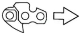
PpaBec Ha MOHTnpaHe Ha CnHIpOT
Ako Kpaot Ha loctot e onpeMeH CO 3aIz3a OIOKByBaHe, BHIMaBajTe NOeTOKOT Ha BLeueHbETo 3a CnHpOpT Da Ce BMETHe npabINHO BO ppa3HHNHTe Ha 3aIcHTe (cI.6).
- Поберета далл кинот за држеве на кинот (сл. 7.A) e npabnilho CTaBeH ha cBoe MeTO BO OTBOPOT Ha loCTOT. Ako He e Taka, Toraaw BpTeTe ro wpaΦOT 3a 3aDpkaHa cnHupot co wpaФцИrep (cI. 7.B)doEka Klinhot He ce noCTaBn dokpaj.
- NocTaBeTe rno NobTOpHo npeHOCHNkOT 6e3 da rH 3aTeRHeTe Ha HABPTKnTe DOKpaj.
7.ИиВртete ro wpafoT 3a 3aDpHa Ha cnHnIpOT (cI.8.A)doEka He nocTnHte npabnHa 3aTeHaTOCT Ha cnHnIpOT.
8.ДржкголocOT noDnHAT,Зашрафete RIN shpaФOBHTe Ha KapTePOT Dokpaj co NOMOW Ha npInLoJHeHnOT KnyC (cI.9).
4.2.1 KoHTpOla Ha 3aTeRHaTocTa Ha CnHnIpOT
IpoBepTe ja 3aTerHaTOCTa Ha cHnIpOT. 3aTerHaTOCTa e npabInHa Kora,dpKejKn ro CnHnIpOT Ha CpeDnHaTa Ha loCTOT, HocaHTe Ha npenocOT He n3JeYBaat OD leKnUTeTo (cN.10).
5. ROMAHДИ 3A KOHTPOJA
5.1 IPEKHHYBAU 3A PAJIeHbE/ TACEHbE HA MOTOPOT
OBO3MOxHyBa 3aCTaHyBaHBe n naIeHbe Ha MOTopOT (cI. 11.C).

MOTOPOT MOHe Da Ce 3aapani n da pa6oTn.

MOTOPOT 3aCTaHyBa.
OTkaKoKe ja npHTnCHete KOMaHdAta 3a 3actaHyBaHbe, IpeKNHyBaOT aBtOMaTcN Ce BpaKa BO N03uJaTa 3a NaIeHe, "I".
5.2 KOMAHDA IPN PN3NcN (CTAPTEP)
Ce KopnCTn Kora ce naJIn CTyJeH MOTOp. KomaHdata 3a cTapTePOr IMa DBe No3uN:

I03njuA (cI. 11 A)- cTapTepe t e ncknyeh (HopMaJHa pa6Ota n naJIeHe co 3arpeaH MOTOp).

I03njuBA (cI.11.B)-CTapTepoTe aKTHBnpan (3a naJeHeHa MOTOpT Ha IaHOb)..
5.3 KONQUE 3A KOMAHJATA HA YPEJOT 3A NOTTKHBUHBE (NPIMEP)
Co npHTnCKaHBe Ha rYmHoTO KOnHe 3a ypeDoT 3a NOTTnKHyBaHBe, Ce HNtUpa RopINBO BO KOLeKTOpOT 3a NOBLeKyBaHBe Ha RopINBOTo CO uTO Ce OJeCHyBa NaJIeHBeTO Ha MOTopoT (cI.12.A).
5.4 KOMAHDA 3A BEHTNJLOT 3A DEKOMPECNJJA (CAMO 3A MODEJOT SP 526)
Ako ro npntnche Te BeHTnIOT (cI. 13.E) KOMnpecnjaT a BO uINHapoT ce HamaLyBa n NaJIeHbTo Ha MaunHaTa Ce OdBnBnOJIeCHO.
5.5 KOMAHДA HA PAчHATA 3A 3AБР3YBAyOT
OBO3MOKBya perylaunja Ha 6p3nHaTa Ha cHnIpOT.
PaKaTc o KOMaHdTa 3a 3a6p3yBaHbe MoKe da ce aKTHBnpa (cI.12.B) cAmo co NCTOBpeMeHo npITnCKaHe Ha paKaTa 3a ynpaByBaHe co 6loKaAdTa Ha 3a6p3yBaUOT (cI.12.C).
IpaBnHaTa 6p3nHa Ha pa6Ota ce noCTnHyBa Kora paKaTc co KOMaHdata 3a 3a6p3yBaoyot (Cn.12.B)e npNTnchata doKpaj..
5.6 PAUHA 3A BJOHHPAHE HA 3A6P3YBAQOT
PaKaTa 3a 6IoknpaHe Ha 3a6p3yBaOcT (CJ.12.C) OBO3MOKByBa aKTHBnpaHe Ha KOMaHdAta 3a 3a6p3yBaHe (CJ.12.B).
5.7 PAUKA 3A PAUHO IAIJEHbE
OBO3MOxHyBa paHNo naleHeHa MOTOpOT (cI. 11.D).
5.8 COINPAUHA 3A CHHNUPOT
CnCTem 3a 6e36eHNO cOnnpaHBe KoJUTo ro
6IIOKnapa DVBXHeBeto Ha CINHUPOT BO Cnyauj
Ha NOBpAteH yDAP (KOHTpaydap) BO TEKOT Ha
pa6Otata. Bo Cnyauj Ha NOBpAteH yDAP 3a BpeMe
Ha pa6Otata, KaHO pe3yIITat Ha HeHOpMaJIeH
KoHTaKT Ha BPBOT HA IIOCTOT n CO HAcNlHO
DBNXeHbe HArOpE Ha IIOCTOT wTO ja HOCn paKaTa
da ce yDprn BO npedHATA 3aWHTTA (cI.1.D).
Tpe6a paHNo da ja De6LokHpAte 3a da ja
nCKlyuHTe cOnnpaYkata 3a CInHIpOT.

NcIyueHa cOnpaKa 3a cnHnpot.OBa ce nocTnHyBa Kora 3aHaTa 3aHTNa 3a paKaTa (cI.1.D) e celOcho NOBLeHa Ha3ad npEHaTa paKa DoideKa He Ce 3aIabN.

AKNBnpaHa cOnpaKa 3a cnHnpot. Oba ce noCTnHyBa Kora npedhata 3aHTnTa 3a paKaTa (cI.1.D) e ueLocho TpyHaT a Happei.
He Kopnctete ja Maunhata aHO cOnnpaHaTata 3a CInHIpOT He pa60TN npabNlHo H KOHTAnTpajTe co 3actanHHKOT 3a HeONXoHa npOBepHa.
6. YNOTPEBA HA MAUNHATA
BAHHO Be36eHOnCHNe MePKu WTo Tpe6a Da rncnTe Ce daen H BO norg.2.Ctporo npnpKByajte Ce do Tne ynatCTBa 3a da N36eHHeTcepNo3HN pN3nI IN OnaCHOCTN.
6.1 BOBEHN ONEPAÇN
IpeJa 3aOnuHHe Co pa6oTa, HeonXoHOb e Da cnpoBeTe cepnja KOHTpOIn n Oepaunn 3a da o6e36eDnte DeKa pa6oTata Ke ce OdBnBa Ha eFHKaceH HauHH CO MaKcImaJIHa 6e36eHOCt.
BAHHO MaunHaTc Ce OCTaByBa Co npa3eH pe3epBoap 3a MeuabnHa N 6e3 Maclo 3a PmauKyBaHbe Ha CnHIpOT.
6.1.1 Полненье ratno
Ipei da ja kOpNCHTe MaunHaTa, HanoJIHeTe rOpNBo. 3a NaunHnte 3a noTbYBaHbe Ha MeuabnHaTa n 3a 6e36eHNte HaunHn 3a DOnoJHyBaHBe Ha rOpNBo (BnDeTe nacyc. 7.3.
6.1.2ДононуbaHe MacLo n noMauchybaHe Ha CnHupOT
Ipei da ja kOpNCHTe MaunHaTa,
DOnoJIHeTe MacNo 3a NODMaUKyBaHBe Ha
CnHIpOr. 3a NaHHOT NocTAnKaTa npN
DOOnJHyBaHBe MacNo, BNDTe nacyc 7.4.
6.1.3 KoHTpOla Ha 3aTeRHaTocTa Ha CnHnIpOT
CnpoBeTe rH cHTe onepaunco n3racen MOTOp.
Hocetecehora3awTNTHn paKabu3a pa6ota.
IpoBepete ja 3aterHaTOCTa Ha cHnHIpOT. 3aterHaTOCTa e npabnHa Kora, DpJKejKn ro CnHnIpOT Ha cpeDnHaTa Ha loCTOT, HocaHTe Ha npenocOT He n3JIeRyBaAT od JeKnWTeTo (cI. 10).
3a perylaucija Ha 3aterHaTocta Ha cHmuPoT:
- pa3la6abete rH wpaΦOBHTe Ha KapTepot CO NOMOISHa npHIOJKeHNOT Knyh,
- BpTeTe ro 7paΦOT 3a 3aDp7ka Ha cnHμnpOT (cI. 8.A)doEHa He nocTnHHeTe npaBnHa 3aTeHnatoCT Ha cnHμnpOT
3.Држевуглгюлстот подигнат,зашафete Гишаловпеса Картетор дokрась сомош на пиложенnot кун (сл.9).
He pa6oTe co Ola6aBeH cHHnnp 3a Da He npedn3BnHaTe onachn COcto6n BO CnyuH Kora cHHnpoT MOHe da N3ne3e od 3annte.
BAHHO Bo TeKOT Ha npBaTa yNoTpe6a, HeonxOHa e YecTa npOBepKa 3apaN npOBepKa Ha leKnIeTeTo Ha cnHIpOT.
6.1.4 NpOroTOBHa Ha MaunHaTa 3a pa6oTa
- YpeI npOTnB CmP3HyBaHbE
Ako ja KopnCTnte MOTOpHaTa Nnla Ha TemnepaTpyn NOHcN O+5°C, Tpe6a Da ro Noctabnte ypeoT npOTNB CmP3HyBaHe npei Da ja 3apaJIte MaunHaTa 3a Da n36erHete FopMnpaBe Ha mpa3 BO KapbypatOpOT wTO nToa Ke ja HamaJIMoKHOCTa Ha MOTOpT, a CO Toa Ke DojDe I DO HeNPaBUNHa pa60Ta Ha MaunHaTa.
MaunHaTa Ce DoCTaByBa Co OTBOp 3a BeHTnlaunJa NoCTaBeH Ha KaNaKOT 3a CInIHApOT 3a Da OBO3MOHyBa IpTOK Ha TOnOJI BO3DyX BO MOTOPOT.
Bo HopmaHn yCIOBn, (TempepaTpyn NOBcOKn Od +5° C), Tpe6a Da ja KOpNCTnte MaunHaTa Ha HOpMaIeH NaHH, T.e. KaKo ITO e peryInpaHa BO MOMeHTOT Ha npOu3BODCTBOTO.
3a da npemHeTe OJ HopMaJIHHOT peKIM BO peKIMOT npoTHB 3amp3HyBaHbe (I o6paTHo):
- 3aCTaHete ja MaunHaTa (nacyc 6.6):
2.ИЗВаДeTe ГКанАКOT HaФиЛТeрOT 3a BO3dUx И ФиЛТeрOT 3a BO3dUx (nacyc 8.2);
3.a Kaj mojelnte SP 386,SP 426:
-OTUpaFeTe ro KanaeTo npOTNB CMP3HyBaHbe Oc CBOeTO MeCTO OdDecHO Ha KaNakOT 3a UINHApoT (Cn.14.A); -CBPTeTe ro KanaeTo npOTNB CMP3HyBaHbe TaKa WTO CmboJ0T 3a Cher Ke ce HAOra Odo3doJa Taka WTO OTBOPOT 3a BeHTnlaunja Ke 6nDe OTBOpEN (Cn.14.B);
Bo TeKOT Ha npBNTe 6-8
Yaca od paobota Ha MaunHaTa, KopnCTeTe IOTMOTOPOT Ha MaKCHMym BpTeHH.
BAHHO
3aTaHeTe ja MaunHaTa (nacyc
6.6) npn MeHyBaHBe Ha loKaunjata Ha pa6Ota.
6.6 3ACTAHYBAHbE
3a da ja ncknyute MaunHaTa:
1.Пуштete Г рачkaТа 3a KOMaHДа
Ha 3a6p3yBaYOT (cI. 12.B)и
OCTaBeTe FO MOTOpT Да pa60TN co
MHHIMVM BPTEKИ YUITE MaIky.
2. PnHTncHeTe ro npEKNHyBaoy (cI. 11.C) BO no3njuja «O»
3. NooekajTe Da 3aCTaHe CnHunpoT.
WToM Ke ro cTaNTe 3a6p3yBaHbeto Ha MNHMym,Notpe6HN Ce HeKoNHy ceKYHn nped da 3acTaHe CNHUnpot.
MToPOT MoKe Da e MHOry BpeI BeHaaw no racheHe. He donnpajTe ro. NocTOn onaCHOCT OJ oneKOTnH.
6.7 IPO PABOTATA
-OTCTpaHete ro kanaheTo Ha CBeKnKhata (cI. 31.A).
-CTabete ja 3aunntata 3a loctot.
-Octabete ja MaunHaTa Da ce n3laN.
- Pa3la6abete rHaBPTKHe 3a
ФИКсИра№ He Na loCTOT 3a Да ce
HamaJIи 3aTerHaTOcTa Ha CINHIpOpT.
- y6aBO nCHCTeTe ja MaunHaTa OД npaunHa n HeuNCTOTn n OTcpaHete rCtte OCTaTOU n OCEHeBETO n TaIOn3HTe OD MacNoTo OD CnHnIpOT (nacyc 7.5; nacyc 7.6).
-Провере Te Ддп Деловite ce pa3na6abehn Илп OwTeTeHn. Ako e notpe6Ho, 3amHeTe rOwTeTeHnTe DeIOBn I 3aTeHETe ra pa3na6abehnTe UpaФOBn Hn HabrTHN.
BAHHO 3actaheTe ja MaunHata (nacyc 6.6), otctpaHete ro Kaanayeto Ha CBeKnHaTata (cn. 31.A) n CTabete ja 3auTntata cekoJnat Kora ja ocTabate MaunHata 6e3 Hnd3Op nn Kora Hema da ja KopnCTnte.
7. PEOBHO ODPKJYBAHBe
7.1 ONTO
BAHHO Be36eHOCHTe Mepn ITO Tpe6a Da rncIeIte ce daene Hb nOr.2.Ctporo npndpHyBaJTe ce do Tne ynatCTBa 3a da n36erHeTe cepno3HN pN3nIN nn OnacHOCTN.
Ipea n3BpwnTe KaHBa 6nlo KOHTpOJa, NcHCTe Tn Hn HnTepBeHnpajTe kaj ODPHyBaheTo/ peryaJata Ha MaunHaTa:
3actahte ja MaunHaTa;
- Noyehajte cHHnpoT da 3actane Heocho;
CTabete ja 3aawthntata 3a loctot dypn n npn HHTepBenuja Ha camnot loct nn Ha cHnnpOT;
- OtctpaheTo hanaeTo Ha CBeKnHkata (cI. 31.A);
- Поверета далу MOTOPе COODBETHO n3naheH;
- npouhtajte rncoodbETHNE ynatCTBa;
Hocete cooDBetHa 6nke,pa60THN YEBNI H3awTHTH N OYJla.
3aueCTeHOCTa H BNCOT Ha HHTepBENuJa ce DaeneH BO "TabelaT a 3a ODPKByBaHe" (BnTe nOJIabJe 12). TabelaT ro npKaKyBa ONcerOT wTO Ke BN NOMORHe npN ODPKByBaHe Ha eFNIKAChOCTa N 6e36eHocTa Ha MaunHaT. Bo Hea ce npKaKaHNrIABHnTE INHTepBeHcUNn INpeDbNdeHnTE INHTepBaJIN 3a CeKOJA OD CTABKnTe. N3BpWeTe ja COODBeTHata NOCTaNkA PpeN pBATA nojaba.
- YIOTpe6aTa Ha pe3epBn DeIOBn I DOONHHTeHa ONPema KOnuTo He ce OPIINHaJIH, MoKe Da DOBeDe Do HecaKaHn eFeKTH Bp3 pa6oTata N 6e36eHocTa Ha MaunHaT. PpOIN3BOInTeJot ja OTpPa cTa OndROBOPHOCT BO ClyujA Ha WtETN INI NOBpIN PpeIN3BnKaHN O TAKBN PpON3BOHN.
OpHnHaHnTe pe3epBn DeIOBN ce Ha6aByBaat BO cepBnCHnTe ueHTPN nn Kaj aBTOpN3npaHnTe 3actaHnU.
Hnkoraaw He KopncTeTe ja MaunHaTa CO KOpNCTeHN Nn OwTeTeHN DeNoBn. OwTeTeHnTeJeNoBn ce 3aMeHyBaat, Hnkoraaw He ce nonpaBaaT.
BAHHO Cnte pa60n 3a odpyBaHe n perynaunja konuTo Hece onnuaH BO Oba yNaTcBO Tpe6a Da ce H3BpwaKaj 3actanHKOT Nn BO OBnacteh cepBnC.
7.2 NOIROTOBHA HA MEUABHATA
ObaMaHHa HMa DBoTaKTeH MOTOp
n pa6OTn Ha MeWabHnOd 6eH3nH
n MacNo 3a NpMaUkyBaHe.
BAHHO YnoTpe6bata Ha cAmo 6eHNCe OwTeTyBa MOTOpOTn Ce n3HyDyBa r6beHe Ha rapaHunjata.
BAHHO KopncTe cmo ro npBO n IOMaKyBaHu CO BnCOK KBaIHTe 3a OApKyuBaHe Ha MaunHaTa N 3a da rapaHTnpaTe TpaeHBe Ha MexaHnKInTe DeIOBn.
7.2.1 KapaHTepnCTnHa 6eH3nHOT
KopncTeCe camo 6e3oJIOBEN 6eH3nH (3eJIeH 6eH3nH) co 6poj Ha OKtaHN He nomaI od 90 N.O.
BAHHO 3eHnOT 6eH3nH CO3daBa TaIor BO pe3epBoapoT aKO ce cyBa NObEKe OD DaB MaCeu. CekoraW KopncTeTe CBek 6eH3nH!
7.2.2 KapaHTepnCTnHa MaCNoTo
CTaBajTe cAmo CnHTeTNUKO MacNo OJ BpBeH KBAJIHTET, HAMEHET 3a DBOTaKTHN MOTOpN CO CneUPhiUeH MInHMym JASO FC. Kaj 3aCTaTNHKOT MOHe Da rH HajDeTe COODBETHNTe MACla, CO3daJeH N 3a OBOJ BVID MOTOP, DO OHOJ CTeIeH KOJ rapaHTnpa NOROLema 3aWHTTa. KopNCTeHBeTo Ha OBHe MACla Do3BOJyBa COCTaByBaHbE Ha eDHa MeuABHa OD 2,5%, WTO 3NaH 1 DeI MaCNo Ce MeHa co CekOn 40 DeJa od 6eH3nH.
7.2.3 IoIroTOBHa HHOH3epBaunja Ha MeuabHnHaTa
Ta6eIaTa rH nocOuyBa KOINuHNHe 6eH3nH
macNo wTo Tpe6a Da ce KOpNCtA 3a
da ja NODROTbInTe MeuABnHaT.
3a noDroTOBka Ha MeShaBuHaTa:
- CTabete BO eDen CaI np6JHKHO NOLOBnHa OJ KOJIuHnHaTa 6eH3nH.
2.ДоадajTe ro ueJIoTo macNo.
3.ДоадajTe ro octaTOKOT Od 6eH3nHOT. - 3aTbOpTe ro KaNaKOT nI3MeWajTe eHeprNCHo.
BAHHO MewsabHaTa noDneKn
Ha cTapeeHe. He noDrToByBaJTe
TOLEMN KOJIUNHn Ha MeuabnHa 3a da Ce n36erHe oopmnpahe TaIor.
BAHHO 乌巴te rno do6po o6e36eene HnIeHTnKHyBaHN KOHTeJHePnte Co MeaBHaTaN CO bEN3HOT 3a da Ce n36BerHe 3aMeHa BO MOMENTO HA KOpNCTeHBe.
BAHHO Od Bpeme HabpeMe YnCTeTe rN KOHTejHePte 3a 6eH3nH N 3a MeWAbnHa 3a Da ce OTCTpaHt eBEHTaJIHNTe TaI03n.
7.3 NOJIHEBe TOpNBO
Hora MaunHaTa He pa60Tu CO H3BaDeHO Kaaye Ha CbeHnHaTa.
Ppe nolhe:
- IpoTpeCeTe ro eHeprNHO pe3epBoapOT 3a MeuabHa.
- NocTabete ja MaunHaTa Ha pamHa NOBpUnHa, BO Cta6nHa No3nJa co KaNaYeTo Ha pe3epBoapOT 3a MeuabHnHaT oDrope.
3A6EJELHKA Ha KaNaueTo 3a pe3epBoapOT 3a MeuabHnHaT (C1. 32.A) ro mca CneHnOT cM60I:
Pe3epBoap 3a MeuabHaHa
3.ИсунsteteToКанayetoHape3epBoapOT BOKpyr3aDaCeH36eHHeHAbIeRyBaHBe HeuNCTOTnПи ПОЛHHeTO.
4. OTBOpTe Ro BHIMaTeJIHO KaNaYeTo Hape3epBoApOT 3a MeUaBnHa 3a Da CeHcNyTu INPTUCOKOT NocTeNeHo.
5. HanoJIHete co INHa n He cTabajTe oMewaBnHaTa Do rPNoTo Ha pe3epBoapoT.
3A6EJIeIKA Iodeka ja KopnCTnTe MaunHaTa, MoKe Da ro npOBepyBaTe HNBOTO Ha rOpHBOTo BO pe3epBOapOT npeky COOdBETHOTo np03Opue (cI. 32.B).
7.4 NOJIHEHe HA PE3EPBOAPOT CO MACJIO 3A CnHUPOT
3A6EJIeUHa Ha KaIaYeTo 3a pe3epBoapOT 3a MaCIoTO 3a CnHpyIpOT (cI. 32.C) ro IMa cIeHNOT cM6OJI:
Pe3epBoap 3a MacNo 3a CnHnIpO
BAHHO KopnctTe nchnyuBO MacNo HameHeTo 3a MOTOPH NINN INN MaCNO CO aINTNB 3a MOTOPH NINN. He KopnctTe MacNo wTO CODPKN HeHCCTOTTN 3a Da He Ro 3anyuHTe FNTepOT BO pe3epBoapOT IN TpaJHO da ja OWTeTNE yMnata 3a MacNo.
KopncTeHe MacNo Od BpBeH KBaJIHTeBaJxH npeDycIOB 3a OdpKyBaHbe eΦnKaChaNOMaIHaOCT Ha CnTe DeIOBn 3a CeYeHb;KOpncTeHe MaCNo CO lou KBaJIHTe TcnpeyBa NOMaUKyBaHbTo I Go HamaIyBaBpEmTpaEHeTo Ha CnHIpOT N Ha LOCTOT.
-Донон electrodoKpajpe3epBoapot 3a Maclo (co nHka) cehojnat Kora ДОПOLHyBaTe roPnBO:IMajTe npeBnI DeKa KaanuTeTOT Ha pe3epBoapot 3a Maclo Ce pncMeTyBa corglacho NOTPOwYBaHaTa Ha rOpNbTo. TaHa ce H36erHyBa pnsIKOT da ja BkIyUyBaTe MaunHaTa 6e3 noMaChyBaHe.
7.5 YNCTEHe HA MAUHHATA HAMOTOPOT
Ha Kpajot Ha cekoja pa6ota,
nchctete ja MaunHaTa DeTalHO od
npab N octatoOn npn pa6ota.
3a da ro HamaJInte pN3NKOT oN noKap: -OdpKHyBajTe ja MaunHaTa, a Oc06eHOMOTOPN 30HaTaNpNDyUByaHT6e3OCTaTOuN Od CeueHeTo, rpaHN, IINCTOBN INpeKymepHO MacNo, -YeCTO YnCTeTe Rn KpNJcaTa Ha cINJHHapOT CO KOMPnMnPaH BO3dyx (cI. 33).
3a da n36erHeTe nperepeBahe
H deΦeKTH Ha MOTOPOT: peWetKaTa 3a BWMyKyBaHBe BO3dyX 3a IaIeHbe (cI. 34) Tpe6a da 6nde cekorawu HCTa N 6e3 OCTaTOU Od ceYeHbeto nn rY6pe.
OdpkybajTe ro odJeIOT kaj pfknjata 6e3 octaToOn OD ceYeBeTo Hn ny6pe (c1. 35) BaTe Ro KapTePo HA pfKnjata (nacyc 4.2) nocTabeTe r OdHOBO npabInHO Kora Ke 3aBpUnTe co pa6ota. Cekon 30 yaca, Tpe6a Da r noMaHkate BHaTpeShHOT nePHNue Kaj 3actanHKnOT.
7.6 YNCTEHE HA CINHUNPOT
No cekoja ynoTpe6a,OTcTpaHete rN oD cHHnIpO TcTe TpaR N Od ceuehbeTo Hn TaIo3N Od Maclo.
Bo clyuj ha rolemn HeuncToHnn 3aMaCTeHOCT, n3BaTeTe rO CnHpOpT n octaBeTe rO da NoCTOn BO caD co OpeJeH deTeprEHT HeKoJky YacOBn. Notoa, HcpePeTe rO BO uCTa BOda n HcnpckajTe rO COoDBeTeH cnpej IpOTNB Kopo3nja npd Da rO NOCTaBNTe Ha MaunHaTa.
7.7 KJIIN 3A BJOKHPaHbE HA CnHcNPOT
Ipeid cekoja ynoTpe6a, npOBepyBajTe ja cocto6ata Ha KInHot 3a 3anpaHe Ha cnHnnpot (cI.1.H) nOsbote ro kora pe3yItaTne He ce 3aDOBOJInteHH.
7.8 HABPTH N IUPAΦOBN 3A ΦHKINPAHbE
- Pnpd cekoja ynoTpe6a, npOBepTe ro 3aTeRhyBaHbeto Ha CnTe UpaΦOBN HABPTKN 3a Da CE yBepnte DeKa MaunHaTa e BO COctoJ6a 3a 6e36eDHa pa60Ta.
- Ппд сени差别,在оверуьajte Даи рачкпсе сцрто ксран.
8. BOHPEДHO OДРЖУBAHБE
8.1 OTBOPN 3A NOДMAUCHYBAHBE HA MAUNHATA H A JIOCTOT
IpeDceKoJdHeBHaTa pa6Ota, n3BaTeTe ro KapTePoT od pPnHcNjaTa (nacyc 4.2), n3BaTeTe ro IocToT nIpoBepTe daHn OTbOpHTe 3a NOMaChyBaBe Ha MaShHaTa (cI. 36.A) n Ha IocToT 3a HabeDyBaBe (cI. 36.B) ce 6loKnpaHn.
8.2 YNCTEHe HA ΦHJTEPOT 3A BO3dYX
BAHHO YnCTeHbeto Ha nHTepOT 3a BO3dyx e 6nTHo 3a do6pa pa60Ta n BeKOT Ha cAmata MaunHa. He pa60TeBe3 nHTep nn CO OWTteH nTep 3a da He npedn3BnKaTe HENOpBaNnBn OWTetyBaHa Ha MOTOPOT.
YnCTeHbTo Tpe6a Da ce cnpoBeyBa cekon 8-10 yacobn pa6ota.
3a yncTeHe Ha qHnTepeoT:
- OTKaueTe ro KpuiuTeTo (cI. 37.A) n 3BaJeTe ro KaanakOT (cI. 37.B).
2.ПиТСНЕТВРСТЯМETALHNOTДELODФИТЕТОЗБДУXДОДЕКАHECSLYSHET3ByKHaKINKHYBaHBe(cI.38.A).
3.ИЗвадеTe ro ФинТерOT 3a BO3dYx (cI.38.B),notчуКнУВajкn ro MaIky 3aДа ja nCTpeCeTe HeuNCTOTnJaTa n NCHNCTeTe rO CO MeKa YETHa.
4.AKOΦHITepOTce3aTHeueLOcHO,n3MnJTe ro co yIcT 6eH3nH.Bo cIyuaJ ha yNoTppe6a Ha BO3dYx IOI npHTuCOH,HaCOUte Ro BO3dYXOT ODN BHaTpe KOH HAdBOp(cI.39). - Ctabete ro fHntepoT (cI. 40.B), NOBLeueTe rO MeTaJIHHOT dIeI (cI. 40.A), Tpe6a Da clyuHHeTe 3ByK DeKa fHNTepoT ce 6loKnpaI Ha CBOeTO MecTo.
- Ctabete ro Kanayeto (cI. 41.A) BnImaBajKn DeKa CITE DeIOBn Ce npabInHO nocTabeHb BP3 cINHHapOT (cI. 41.B).
- 3aKaueTe ro KpuiIeTo BMeTHyBajKn ro npBO DoJIHnot DeI n Notoa npHTnCKajKn BP3 rOpHnot DeI dOdeKa He cLyuHHeTe 3ByK (cI.41.C).
8.3 JIEXHNIITE CO ΦPINKUJA
EHaM MeceHNO, npOBepyBajTe ro HHTerptETOT Ha MetaHnOT peMeH KOJ ITO ce 06BNTKyBa OKOly JExNtETo 3a pInKunjata Kaj 3actanHKnOT. PEmeHOT Tpe6a Da ce 3aMeHN Kora Ke ce n3a6n nn DeOpMnpa.
8.4 KJIHH 3A IPEHOC HA CINHPOT
Co nomou Ha 3actaHnKOT, peoBHO KOHTpOJInpajTe ja coctoJbTa Ha 3anuTe H 3aMeHeTe rKora Ke 6nDat n3a6eHN.
He mONTpajTe HOB cHnnp CO CTap 3a6eU nn o6paTHo.
8.5 KOHTPOJHA CBEKNHATA
Do CBeKnUkata (cI. 31.A) MoKe Da ce npHCTaH aKO rO n3BaDnTe KaNaKOT 3a FInTepoT 3a Bo3dyx (cI. 37.B).
IobpeMeHO,OTkaYeTe ja nHcNCTeTe ja CBeKnKhata 3a da rN OTcTpaHNTe eBENTyaJIHNTe TaIO3n CO MeTaHa 7NaTyna (cI.42.A). IpoBepTe ja n O6HOBeTe ja ToUHaTa OdaJeueHoCT mey eNeKTPOndte (cI.42.B). NocTabete ja CBeKnKhata HameCTO npuBpCTyBaJkn Ja co npNoJKeHnte KJIyuVeBn. CBeKnKhata Tpe6a Da ce 3aMeHN Co dpyra co aHaIoRn KaPaKTepnCTHb BO clyujakora eNeKTPOndte ce pnerOpEHN
Hn HnpaBnHn 30npaHn, nHa ceKoN 100 Yaca yHKnOHpAhe.
8.6 JAAHE 3A IAPJEHe
3aCTaHnHKoT Tpe6a Da r OcMeHN jaKeTo 3a NaIeHe npN npBnTe 3HaBn Ha OwTeTyBaHbE.
8.7 ODPKHYBAHbE HA CHNHPOT CO 3APlu
Od 6e36eHocn npuHHn n nopadn eKacHOCT BO pa6oTaTa, MHORY e BaHHo ypeoT co CeuBOTO da 6nnde do6po Haocptpeh.
OctpeheTo Ha cHnIpOte HeonxOJHO KORA:
-CTpyrotHHTE JNcT Ha npaunHa,
- ceyeheTo ce OdBnBa CO MHOry cnla,
-ceyeheTo He e JInHeapHO,
-Bn6paunntce 3rOJemehn.
-NotpouWbauKaTa Ha rOpINBO e 3roJeMeHa.
Ako cHnHIpOT He e doBOJHO HaoCTpeH, NOcTOn pN3NK OJ IpOTnBydap.
BAHHO IpenopayBame octpeheTo Ha cnHIpOT da ce OdBnBa BO CneuJaIIN3npaH ueHTap,MOKe Da Ce N3BeDe CO COOdBETH anapatn KOI Obe36eYBaAT MInHMaJIHO paCnPCHyBaHe Ha MaTePN IN OCTpeHe KOHCTaHTHO 3a CITE BNDN CEyeHa.
8.7.1 OctpeHe Ha cHnnpOT
OctpeHbeto Ha cInHpOpT ce n3BEdyBa CO NOMoH Ha npIIOJKeHnTe Typnnn Co 3a06JIeHH Cekn HJWTO DnJaMeTap e CneuHueH 3a CHTe BnOBn CInHUPn (BnTe "Tabela 3a OdpKyBaHe Ha CInHpOpT", norlaBe 14) n 6apa oJnUHa CTpyHOCt H NCKyCTBO 3a Da ce n36erHe PpeIN3BKnYBaHe OwTeTyBaHa Ha CeYNBaTa.
3a ocTpeHbe Ha cHnHnpoT:
- 3actaHete ja MaunHaTa (nacyc 6.6).
2.ИЗваде te ja coирачкata 3a cnHIpopoT (nacyc 5.7).
3.Блонирajte roцрсTO loCTOT co noctabeh cnHnnp CO COODBeTHNO7 6LOHaTOp (cI. 43.A), npOBepyBajKn daJIH CNHnIpOT MOKe CNo6OJHO Da ce DBNKn. -
3aterheTe ro cHunpoT doTaMy Toj da ocTaHe Ia6ab (nacyc 6.1.3).
-
Bmethe ja typnjaTao OTbopot 3a 3a6eot,odpkybajnnoctojaHa 3aKocehoc TcIaCHO npOphiNt Ha 3a6eot (cI.43.B). Ynotpe6aTa Ha nloka 3a ocTebe ja OLechya pa6oTaTa co TypnjaTata (cI.43.C).
6.ИЗБЕДУВAJTe cAmO cIa6n DBHKeHbaco TypnJaTa NcKJIyUHBO HaHaNpeD INOBTOpeTe ja OIepaunjata Bp3 CHTe CeHNaBCo ICTa opNeHTaUnja (deCHN JIeBn).
7.Ппевртete Г loctot od pyra t a ctpaHa Ha MeHreMeTo I NOBTOpe Tn OepaunTe Ha npeocTaHaTnte ceuBa. - Побереadingлграинnotа6eц (с. 43.D) Ги Има Ньараздаден BO Ta6elaTа 3a odжуbahe Na синцрOT (norlaBJe 14) ИИЗрмHeTe Ги НерamHInHTe co pamHa Typnja, OKoly npOphNlOT.
- По OCTpeHbeTo, OTCTpaHete ГСИТЕТрагн OД CTpyROTNHN, ИСИСТЕТОИпОмачКajTe ГСИЧИРOT OБИЛно CO macNo.
8.7.2 3aMeHa Ha cnHnIpO Co 3anu
CnHpOTo Tpe6a Da ce CMeHn Kora: -DOLJINHaTa Ha CeYNBaTa Ke Ce HamaJIi 3a HajMaJIky 5 MM, (cI. 43.E), -DbNKeHbETo Ha 3aAnuTe e TeUHO, -6p3HaTt Ha ceeHe e 6abHa n NOBTOpeHnTe OCTpeHa He ja NODOpyBaat 6p3HaTt Ha ceYeHe. CnHpOTo e n3a6eH.
BAHHO Ito 3aMeHaTa Ha CnHUnpoT, Tpe6a YecTo Da ja npOBepyBaTe 3aTERHaTOCTa Ha CnHUnpoT 3a Da rO npOBepTe JeknWTeTo Ha CnHUnpoT.
8.8 OДРИУBAиE HA JIOCTOT 3A HABEDYBAHbE
3A6EJELHCA CTe onepaunuTo ce OndecybaaT Ha loCTOT 3a HabeDyBaHe ce paBOTn 7to bapaat cneuPhuHa KOMPeTeHTHOCT CO aHraKnpaHe COODBeTHa ONpema 3a Da MoKe paBotaTa Da ce N3BeDe npabNHO; OD 6e36eHOCn nPnuHH, Cekoraw e HajdoBPO Da ce KOHTaKTnpoDaBaOT.
3a da ce n36eHHe acnMeTpnuHo KopncTeHBe Ha loCTOT, noTpe6Ho e Toj nepNoDnHDo ca ce npOBepyBa.
3a eФИнСАОДРЖУВа№ Ha loCTOT Tpe6a:
-
Da ce noDmaKyBaat nepHnUHbata 3a OJIOxKyBaHe Ha 3aIuaHnKOT CO npNIOXeHHOT uPn (aKO nMa);
-
Da ce nCnCTn HJIe6OT Ha loCTOT CO COODBeTHa rpe6aIIka (He ce doCTaByBa) (cI. 44.A);
- Да се чист AT OTВОРп Te 3a ЮдмачкУВаHe (сл. 44.B);
- co pamHa TypnJa, (He ce doCTaByBa), Da ce n3BaDat CTPaHnUHnTe TaIO3n I Da ce npamHaT eBENTyaJIHnTe pa3JInKn BO BnCnHaTa MeIy BoDnIKnTe.
8.8.1 3aMeHa Ha JIOCTOT
IocTOT Tpe6a Da ce CMeHn KOra: -Длбочинata Ha 3anuTe Ke 6nDe NOHnCKa OJ BnCnHaTa Ha NoyehHaTa TOUka Ha npEHOCHNkOT (KoH NIKoraw He Cmee Da DonpaT Do DOnHaTa CTpaHa); -BHaTpeuHNOT SnD Ha BOdINkata e NcKOpHCTeH Do ToUka Ha DOnpaBe Bp3 JaHeQT.
8.9 PEGYJALAUJHA HAMHHIMYM
Ako ypeoT 3a ceyebe ce DbHHn Hora MOTOPe e Ha MNHMym, Tpe6a da HOHTaHTnpaTe CO 3aCTaHnHOT 3a npaBnHa pa6ota Ha MOTopoT (nacyc 8.11).
8.10 PEGYLAUJHA HA HAPBYPATOPOT
Kap6bpaTopoT ce perylnpa BO phabpnka BO peKIM Da daBa MaKcImaJIHn pe3yIITaN BO CEKOJA CNTyaUcnja Ha KOpNCTeHbe, CO MInHMaJIHO EMNTnpaHBe Ha IITeTHN rAcOBu IN BO COrJIaCHOCT CO BaKeHHTe 3aKOHn.
Bo clyuj ha lowa n3Be6a, o6paTeCe kaj 3acTaNHKOT da rN npOBepn Kap6bypaTOPOT N MOTOPOT.
PerguauHnHaKapbypatopoT:
T = perулачиja Ha MnHmMyM
L = perулачиja Ha ropnbOT npn MaJa cnJa
H = perулачиja Ha ropnbOT npn roJema cnJa
9. OДЛоЖУBAHБE
BAHHO 6e36eHNOCHHTe MepKuITo Tpe6a Da Ce CneDaT BO TeKOT Ha paHyBaHe ce HabeJeHN Bo nac.2.4.Ctporo npndpkyBajTe Ce Do Tne yNaTCTBa 3a Da n36erHeTe cepNo3HN pN3nU INn ONaCHOCTn.
AkoHema da ja KopnCTnte MaunHaTa NOBeKe o2-3 meceu, Tpe6a da ce npmeHaT HeKoIky peweHja 3a da ce n36eHaT
NOTeSHKOTNI npn O6HOByBaHe Ha pa6OtaTaNIN TpaJHi OwTeTyBaHa Ha MoTOPOr.
PpeoDnlaraHe Ha MaunHaTa:
- OtupafeTe rN DBeTe HABPTKn Ha KapTepot 3a φpHKunjata, n3BaTeTe ro KapTepot n TprHHeTe rN CnHnIpOT n loCTOT.
2.Испаэнete Георбогаотзмасу, CTaBeTe OKoly 100-120 cc cooDbTeH TeueH DeTepeHT n CTaBeTe G KaNaYeTo.
-
NocTaBete ro KapTePoT 6e3 da rN 3aTeHHeTe Ha HABpTKnTe DOKpaJ.
-
3anaIeTe ja MaunHaTa n octaBeTe ro MOTOpOT da pa6Otn DoKeHa He corOpn ceJInot DeTeprEHT.
5.OctaBeTe ro MOTOpOT da pa60Tu Ha MNHmymdoKeHa He coropu ZeIOTO rOpNBO wTO ocTaHaLo BO pe3epBoapOT n BO Kap6ypaTopoT.
- Octabete ro MOTOPOT da ce n3naI.
7.ИЗbaTeJaCBeKnUkHaTa.
-
Bp3 OTBOPHTe Ha CBeKnUHaTa NOLJTe eDHa KaΦeHa JAnuKa Maclo (HOBO) 3a DBOTaKTHN MOTOpH.
-
Повleteе ja HeKoIky paTn paKaTa 3a NaIeHbe 3a Da ro DnCTprNbypaTe MacIoTO BO cUInHapOTo.
-
NocTabete ja CBeKnUHaTa co HABpTKaTa Ha HajropHaTa MOHHa ToKa (da e BNDINO HO 3 OTBOpOT 3a CBeKnUHaTa KORA HABpTKaTa e Ha HajropHaTa No3nCuJa).
11.Исунсте jo TeMeHNo MaunHaTa.
12.Повереталн ha Maшина Иma OштetybaHa.Ako e NOTpe6Ho, KOHTaKTHpajTe co OBlaacteH cepBnceH ueHTap.
- OndoJKeTe ja MaunHaTa: -BO cyBa npocToPja -n 3acOJIHeTa OD loUbBpeMeHcN ycIOBn -Co npaBUNHO NOCTaBeHa 3aHTIa 3a IooTOT -n Ha MeCTO HAdBOp OD DOΦaTOT Ha Deuata, -yBepyBajKn DeKa CTe rN TprHaJe KJIyuEBrTe n ONpeMaTa UTo ja KOpNCTeBTe pRn ODPKHyBaHBeTo.
Kora tpe6a da ja 3anaIte MaunHaTa:
1.ИЗbaTeJaCbeKnUkHaTa.
2. AKTNBnpajTe ja HeKoNHy naTn paKaTa 3a NaIeHe 3a Da Iro eIIMnHnPaTe npEkyMepHOTo MacNo.
3. PpOBepeTe ja CBeKnUkata (nacyc 8.5).
4. NodrotBeTe ja MaunHaTa (nacyc 4.2, norlaBe.6).
10.ДВИЖЕΗΝΤΡΑΗСΝΟPT
Kora ja Hocnte nItn TpaHcnpOpTnpaTe MaunHaTa:
- 3acTaHete ja MaunHaTa (nacyc 6.6).
-NoyekajTe da 3actane CnHnpoT.
-OTcTpaHeTe ro kanaeTo Ha CBeKnKaTa (cI. 31.A).
-CTabete ja 3aunntata 3a loctot.
-ΦaTeTe ja MaunHaTa cAmo 3aДрнaHTe N Da Ce HacOuN loCTOT BO npaBeU CnpoTINBEN OJ npaBeUOT Ha DBNXHe.
Kora ja Hocnte MaunHaTa co Bo3nlo:
- nocTaBeTe ja Ha NaYH Da He npetCTaByBa OnaCHOCT 3a HNKORO
-UBPCTO 6IOKnapaTe ja BO TEKOT Ha TpaHcnpOT co jaXnHa nIN CnHnprn 3a Da n36eHHe Te ppeBpTyBaHe n MOxHo OWTetyBaHe n ICTeHyBaHe Ha rOpNBOTO.
11. NOMOUSHONPABHA
Oba ynpaTCTBO rnpTeCTaByBa cHTe HeONXODHn INDnKaun 3a ynpaBvBaHe CO MaunHaTa n 3a npabNlHO ODPKByBaHe wTo rN H3BpUyBa KOpncnKOT. CnTe INTEpBeHcnn 3a peYlaucJa n ODPKByBaHe wTo He ce ONuShaHn BO OBA yNaTCTBO Tpe6a Da rN CNPOBeDe 3actanHKnOT nIn CneunjaJln3napan cepBnCeH ueTp Bndejkn 3Haat KaKo n rN HMaAT HeONXoDHnTe INCTpyMeHTn CO KOnWTO pa60TaTa Ke Ce 3abPn npabNlHo, 3emajn rO Bo npedn npBo6nTHnOT CTenEH Ha 6e36EdnOCT n YCLOBnTe Ha MaunHaTa. CnTe onepaun WTO Ce n3BeDeHN Ha HeCOoDBeTeH NaHH n OD HeKBaIINΦnKByBaHn INuCa pnpDOHEcyBaAT da Ce n3r6bN CEkoJa φopMa Ha rapAnCuJa n CeKOJ obnK Ha OBpCKa Ha npOn3BOdnteIoT.
- Camo OBlaCTeHITe cepBnCH 3a NOMO MoKe Da rN n3BpUyBaat nonpaBKnTe N OdpKyuBaHbeto uTo ce nO rapaHcunja.
- OblacteHnte cepBnCHn ceHTpn KOpNCtata camo opunHaJIHn pe3epBn DeIOBn. OpunHaJIHnte pe3epBn DeIOBn n dOJOnHnTeJIHa onpema ce cneuJaIHO dN3ajHnpaHI 3a MaunHaTata.
- Pe3epBnTe DeIOBn I DOJOnHnTeJIHa onpema KOnuTo He ce opunHaJIHn, He ce oO6peHn. YIOTpe6aTa Ha HeOpunHaJIHn pe3epBn DeIOBn I DOJOnHnTeJIHa onpema ja OTpna rapaHcNjata.
- Ppenopaybame da ja odheceTe MaunHaTa BO OBlaCTeH cepBuceH ceHTap cekojnat Kora Tpe6a da ce pa60tHa ODPKByBaHe, nonpaBka nI npOBepKa Ha 6e36eHocnTe ypei.
2.5 BESCHERMING VAN DE OMGEVING
- EKSTRAORDIN/ERT VEDLIKEHOLD 15
2.4 VEDLIKEHOLD, LAGRING
7.3 ETTERFYLLING AV DRIVSTOFF
8.7 VEDLIKEHOLD AV SAGKJEDET
For a slope kjected:
8.8 VEDLIKEHOLD AV SVERDET
13. VEDLIKEHOLDSTABELL
14. VEDLIKEHOLDSTABELL FOR KJEDET
| Spor til kjetet | Nivået til begrenserskjærtannen (a) | Filens diameter (d) | |||
| a | d | ||||
| tommer | mm | tommer | mm | tommer | mm |
| 3/8 Mini | 9,32 | 0,018 | 0,45 | 5/32 | 4,0 |
| 0,325 | 8,25 | 0,026 | 0,65 | 3/16 4,8 | |
| 3/8 | 9,32 | 0,026 | 0,65 | 13/64 | 5,2 |
| 0,404 | 10,26 | 0,031 | 0,80 | 7/32 5,6 | |
2.2 CZYNNOSCI WSTEPNE
6.1 CZYNNOSCI WSTEPNE
A这其中 constitutes the most important and most numerous components of the organizational system.
4.1 KomnoentbI Jn MaHTaHa 7
4.2 MoHTaK HAnpaBIAJIOUe IINHbI N3y6aToI cenn..7
5.CPECTBAYNPABILEHNA 8
5.1 BbIKIOHateJIb BHKIOHcHnB/BoKIOHcHn DBIraTeJIa
8
5.2 PnBOD Bo3DyushoN 3acLoHNKn 8
5.3 Hhonka ynpaBleHnHaCOCOM nOdkuKn TOnJIbBa (PpaMep) 8
5.4 Pyuhar ynpaBHeHnA npocSeIeM.. 8
5.5 BIoKIpOBoUHbI pyUar dpocceJIa 8
5.6 RykoTka pyHoro 3anycka... 8
5.7 Topmo3 ueH 8
- 3KcIyATAURA MAsHHbI 9
6.1 PpeBapnteIbHbIe oepaun.. 9
6.2 PpOBepKn 6e3oNaChocTn. 10
6.3 3anyck. 11
6.4 Onncanhe pa6oTbI 12
6.5 PeKOMeHdaaunno 3KcNlyaTaauu 14
6.6 OctaHOB 15
6.7 PocJIe pa6oTbI 15
7.ПЛАHOBOETEXHINUECHKOEOBSCJYKNIBAHNE.....15
7.1 6uee cBeHnra 15
7.2 PnroTOBJIeHne cmeCn 15
7.3 3a npabKa TOnJIbBOM 16
7.4 3aIINbKa MaCna DJIa CEH N B6ak. 16
7.5 OuchTaMaunHbI N DBrHaTeJIa 17
7.6 Ouchka cei.. 17
7.7 Leneynobntel 17
7.8 KpeeKhble raikn BNHTbl 17
8.BHEOUEPEDHOETEXHNUECKOEOBCLUYKINBAHNE
17
8.1 Cma3oHbIe OTBepCTnMaunHbIu Hhbl 17
8.2 OuHCTKa BO3dUshHO fHbTpa... 17
8.3 Kollnak ceniJeHna 18
8.4 Bedyua 3Be3doUka ceu 18
8.5 IpoBepKa cBeu 18
8.6 IychoBoI Tpoc 18
8.7 TexHHuechoe o6cnyKbBaHne 3y6HaToI cen1 18
8.8 TexHnueeOoe 6cIyHnBaHne HappaBlaHoueJ nnHbI .19
8.9 PerynipobKa xoIocToRo xoJa 19
8.10 PerynpoBka Kap6opatopa 19
-
XPAHEHNE 19
-
INPEMEUENIEI TPAHCNOPTNPOBKA 20
- CEPBICHOE OBCJYKINBAHNE IN PEMOHT.. 20
- YCIOBnI rAPAHnI 21
- TABILIaTExHHueCFOOBCJYKINBAHnA..21
- TABJIULA OBCJYKINBAHINI ZENI 22
- BbIbJIeHHe HEnoJIaIOK 22
16.ДОПОЛНITEЛьНОЕОБОУДOBAHNE... 24
1. OBUNIE CBEDEHNA
1.1 KAH CJIeIyET YHTATb 3TO PYKOBOdCTBO
B TeKCTe 3TOrO pyKOBOcTBa OTdJIbHbIe naparpaΦbl, codepkaune Oco6eHNO BaJHyIO INΦOpMaUIO TExNKe 6e3OnaCHOCTn IIN npINCuINax pa6oTbI yCTpOiCTBa, BbIJeJIeHbI CJIeDyUOuM o6pa3OM:
PnmeyAHNE BAXHO
CopeKHT yToHHeNn Hn CcbIKN Ha
dpyTuO paHee ynOMaHyTuO nHΦOpMauHo
TnpeDOrBpaUeHn NOlOMKn
MaunHb nnHaHeceHn yuep6a.
3HaK yKa3bIbAeT Ha onaCHOCTb.
Heco6IIOHeHne DaHHoro IpeDynpexKDeHn MoKeT PnBecTN B NOLyueHnU HaHeceHnTO TaBM N/IINa HaneCEHNO yuep6a.
IyHtbl, 6bpaMeHHbIe cepoIyHHTnPHoI paMHO, cOepKaT OINcAHne OINHOHaJIbHbIX XapaKTepnCTNK, He npncuix BCem MOeJAM, IpeCTaBJIeHHbIM B DaHHOM pyKOBoODCTBe. IpoBepbTe, ecb JI NaDaHHaXapaKTepnCTNkBaWeJ MoJeJN.
Bce 603haeHn "peHn", "3aHn", "PpaBb" n "IeBb" yka3bBaIOTCr OTHcHTeMbHO pa6oero noIoKeHn onepaTopa.
1.2 O5O3HAUEHNIA
1.2.1 PncyHKn
PncyHKn B daHHOM pyKOBoODCTBe
No 3KcNlyaTaun npOHymepoBaHbI
1,2,3 n Tak daJe.
KomnoHeNTbl, pokaahhbie Ha pncyHKax,
603Nauehbl 6yKBaMn A,B,C n Tak daJe.
Ccblnka Ha KomnoHent C Ha pncyHke 2
OcyuectBlaeTcR npn NMOoun fpa3bl: "Cm.pnc.2.C" nn npocTo "(pnc.2.C)".
N3obpaKeHnHa pncyHKax YBIAOTcR
npn6In3ntelbHbIMn.PealbHbIe DeTaJIi
MOrTy OTnUaTbcr OTn3o6paKeHHbIX.
1.2.2 Ha3BaHnI rJaB
Данhoe руковocTBo NOdpa3deJIeTcH NaIaBbI I NyHKTbI.ПункТпOD Ha3BaHHeM "2.1ОБчЕнe"ЯВЯETcNoDpyHKTOM rIaBbI "2.ПраВILAбЗОпасно".СсынHa rIaBbI I NyHKTbI O6O3HauAIOcKpaUeHnE M.II INIpyHKTИ COOTBeTCTByIoUIM HOMePOM.PpIMep:"rI.2"Ил"PyHKT 2.1".
2. ПAPВILA BE3ОПАСHOCTN
2.1 OByeHne
O3HaKombTecb c opraHm ynpabIeHHn HnHaJIeHaaHm HCNoJIb3OBaHHem MaunHbl. Hayntecb 6bICTPO OCTaHaBnBaTb MaunHy. Heco6JIouHeHne Mep npedocTopOHHOCTn n peKomeHdaaN MoKeT npNBecTH N noHapam HnHn cepBe3HbIM TpaBMam.
HnB Koem Cnyae He pa3pewaite NOIb3OBAtbcMaunHOJ DeTAM NIN LIncaM,HeIOCTaTOUHO XopoWo 3HaKOMbIM C npabNlAmn O6paueHnC Hei.MecTHoe 3aHOHOaTeJIbCTBO MOKeT yCTaHaBnBaTb MNHmAlhBbI BO3pAcT NoIb3OBAteJIa.
- HnKOrda He nCnoB3yIte MaunHy, ecIn NOJb3OBaTeJIb yCTaJI, IIOXo Ce6yUvBCTByeT INn HaxOJTcR NOD BO3DeNCTBnEM JeKapCTB, HApKOTnKOB, aIKORoJIr INn BeIeCTB, CHNkaIOuNX ChOpOCTb peΦJIeKCoB IN yPoBeHb BHIMaHIN.
-ПOMHHTe,чTOОнepaTOpИлпОЛьЗВаTeь HeceT OTBETCTBEHHOCTb 3a HeCuaCTHbIe CnyuAn IIN yUepe6,HaHeCEHNbIpyrIM LIncAm IIN INx IMyUeCTBy. ПОьЗВaTeь HeceT OTBETCTBeHHOCTb 3a OueHky NOTeHuaJIbHbIX PnCKOB Ha yUacTKe,Ha KOTOpOM OH pa6OtaeT,КpOME TOrO,ONdoJIKhenPnHrtb BCE Mepbl NpeDIOCTOPoXHOCTN,YTObI OBeCneuHTb CBOIO 6e3OnaCHOCTb N 6e3OnaCHOCTb OKpyJkaIOuNX,BOCO6EHNOCTn Ha CHLOHAX,HePOBHBIX,CHOLb3Hnx IIN HeyCTOuNVbIX NOBepxHOCTx.
- EcIn Bbl HamepeHb I nepeDaT bIIN OdoJHKITb MaunHy dpyrIm Iuam, yOCTOBepbTeCb, YTO OHN O3HaKOMnJIncb C yKa3aHnA MNo 3KcNlyaTaCn, n3LOXeHHbIMB HaCToAeM pyKOBOdCTBe.
ДяИСПОЛБ3OBAHЯMaSHHbIДЯВалКи ИOBpe3KNBETBEHHeO6XODMO npoTn CneuaJIbHbI Kypc ObyeHna.
2.2 IPEДВAPИTEЛьНьIE ONEPAЦИ
CpeDCTBa HndnBnDyajbHoJ 3aunTbi (CN3)
HaedeBaIte npIneraIOuSyIO 3aunTHyIO OeJdy C 3aunTOI ONope3OB, npOTnBOBn6paUOnHHbIe NepuaTKn, KACKy, 3aunTHbIe OOKN, nbJIe3aunTHyO MACKy, HayuHNIkDnI 3aunTbI OPraHOB CnyxHa I O6yBc 3aunTOI ONope3OB IN C HeckoJIb3AJeN NOoWBOI.
He haedeBaIte wapbI, xaIaTbI, KOJIbe, 6paCneTbI, pa3BeBAIOUcYOCr ODeJy, a TaKHe OeJHy CO UHypKaMn I raIcTyKn, a TaKHe IIObIe BnCraYNe NIN ShIpOKHe aKCECCyApbl, KOTOpBle MOrY T3acTpRb B MaUNHe NIN B ppeDMtax N MaTePnaJax, HaxOJaUxXcRa Ha pa6OyEm MeCTe.
-Должнblmобра3OMco6epnteДИHHHbIe BOJOCbl.
BnraTeH BHyTpEHHero CropaHn: TOnnBO
ONACHOCTb!BeH3nH n Cmecb JerKOBOCIIaMeHrJOTcR.
XpaHnTe 6eH3nH n Cmecb B CneuaJIbHo npedHa3HaueHHbIX dIaTOTO KaHnCTpax, OMOJIOrpoBaHHbIX dIaHHo ueN, B 6e3OanachOM MeCTe, BdAnOT HcTOUHNKOB TeIIa N OTKpbITOrO PImaMeHn.
OuHauTe KaHnCTpbI N MeCTo XpaHeHnT OTOJIbA OT OCTaTKOB ONJIOK, BETOK, JNCTbeB IN3JIINKOB CMa3Kn.
He octablan Te KaHnCTpbI B npedeJax DoCraeMoCTn DeTei.
He Kypnte Bo Bpem npnroTOBJIeHn Cmecn, BO Bpem 3aIpaBKn NIN DOJIbKn TOnJIbBa, a TaKHe BOO6e npn ObpaueHn C ToNJIbOM.
3aIbAaTe TOnJIbO Yepe3 BOpOHky, TOJbKO NOt OKpbItbIM He6OM.
- 136eaiTe BdbixaHnna napOB TOnnlaBa.
He do6abJnTe TOnIINBO n He ChImaIte npo6ky 6aka, KOrda DBrIraTeIb pa60taeTnn KOrda OH rOpAyn.
- Medlenho OTKpoIte npo6ky baka, YTObI NOCTepeHNO c6pocNTb BHyTpENHee daBHeHne;
He np6nnaTe nIaMgK 3apabOCHOMy OTBepCTNUo 6aKa, YTO6bl npOBepNTb erO coDepeHmoe.
B clyuae pa3nBa TOIINBa He 3aynckaiTe DBNrTaTb, y6epnte MaunHy C MeCTa pa3nBa TOIINBa H npMNTe Mepbl NO ppeDynpexdEHNIO BO3ropaHnI Do TEX nOp, nOHa TOIINBO He NCnapITcN ero napbl He pacceOTc.
- HemeIeHNO y6epnte BCE cIeDbI TOIIIBa, KOTOpoe npOJIIOCb Ha MaunHy nIN Ha 3eMNI.
Bcerda Bo3BpaaIte Ha MeCTO n IIOTHo 3aKpyuHbAIte np6Kn 6aHa N KaHnCTpbIC TOJIINBOM.
He 3anyckaIte MaunHy B MeCTe 3anpaBKn; 3anyck DnirataTeIa Heo6xOdmo OcyuecTBJIbTb Ha pacctOarHIn He MeHee, Yem 3 MeTp a OT MeCTa 3anpaBKn TOnJIbVOM.
- I36eraIte KOHTaKTa TOnJIbBa C ODeJdoN, B clyuae ee 3aIrpA3HeHnI, nepeOeHbTeCb nepeD 3anyCKOM DBrIgTaTeJIa.
2.3 BO BPEMRA PABOTbl
Pa6oynyuaCTOK
He BkIIOuHaIte DnIRaTeJIb B 3aKpbITOM npocTpaHCTBe, rJe MOKeT CKONITbcr onaChbYrApHbIra3.3aynck DOJXeH npOn3BOINTBcRA Ha yLIue HINB XopoIo npOBeTpBaemMecTe. He 3a6bIBaIte O TOM, YTO BBIXIONHbIe Ra3bl DnIRaTeJIa TOKCNUHbI.
Bo Bpem 3ayncKa MaunHbI He HaprabTne rnyuNTeNb I, CJeIOBATEJIbHO,BbIXONHie Ra3bl Ha JeKOBOCnAmEHNOUncE CaTePnaJIbI.
He nCnoJIb3yIte MaunHy BO B3pbIBOOnaCHO
cpeJe, NObJIn3OCTn OT rOpUChx HnIDKOCTe,
ra3a nnPiNbII. 3JeKtpnueCKne KOHTaKTbl
nnMexaHnueCKoe TpeHne MOryt
CREhePnpOBaTb NCKpbl, KOTOpBle MOryt
PnPBecTn K Bo3rOpAHIO PbIIN nn NapOB.
Pa6oTaIeToIbKO npn DHeBHom CBeTe nII npn XopoWem NCKyCCTBeHHOM OCBeUeHnn, BycIOBnxXopoWeBNDIMOCTn.
Ha pa6ooyem yuaCTHe He doJHKHO 6bITb B3pocIbIX IIODei, DeTei N HINBOTHbIX. Heo6xOdImo, YTO6blpyrO B3pocJIbIy eJIOBEK CMOTpeI 3a DeTbMn.
IpoBepbTe,TO DpyHne IIOHn HaxoTcHa paCCToHHN,NO MeHbWeMpe,15MeTPOB OT paAnyca pa60TbMaunHbl.
- I36eraIte, no BO3MOHHOCTHn, pa6oTaTb Ha MOKpoi HJI NCKOJIb3KOJ NOUBe, HJI Na IIO60i KpyTOH HEPOBHOI NOBepxHOCTH, He OBeCneuBaIOUeYCTOUYBOCTN onepaTopa BO BpeMpa6oTbl.
- O6paaTe oc6oe BHNMaHne Ha HepOBHOCTn NOyBbl (KouchN, KaHaBbl), Ha yKIOH, Ha cKpbITbIe ONaCHOCTn I HaJIuHc BO3MOXHBIX PpeTCTBNI, KOtOpbIE MOrYr OppaHnHTb BNIMOCtB.
CobIIOaIte oCTOpOHHocTb, pa6oTaY pIOM C o6pbIbAMn, KaHabAMN 6epeAmN BDOeMOB.
Korda Bbl pa60TaTe Ha MaunHe prdom C npoe3KeJ yactbIO, yuHTbIbaTne NOTeHuaJIbHOe npncyTCTBHe TpaHCnOpTHbIX cpeDcTB.
-Bo n36eKaHne noKapHoN onaChocTn, He octabIaIte MaunHy c TOpAum DbIraTeJIem
CpeHnIHCtBeB,CyXoTpaBbI Ndpynx IeKOBOCnlaMeHHOxxCaMaTePnaNoB.
IpaBnla nobeHnBa BpeMa pa6oTbI
Bo Bpempa60bI npoHOn ydepnBaHTe MaunHy dBympykamn (JeBa pyKa DoJHHa HaxOHTbcn Ha nepeDnepykoTKe, a npabay pyKa Ha 3aDHe pyKoTKe, daKe ecIn onepaTop leBwa) nNoaJIbSe OT BCex YacTee Baawero TeJa.
- PpIMnTe yCToHnBOe n npOuHoe nIoJxHHe, n CO6JIHOaIte oCtOpOxHOCtB.
- N36eRaTe nCNoJIb3OBAt b IecTHNuI H HeYCTOnuHBbI pAaTΦOpMbI.
- I36eAte pa6oTaB B ODNHOy NIN BdaJIH OT JIODeN, YTObI BBIMORJIN O6paTNTbCRA 3a NOMOsbIO pni HeCuaCTHom Clyuae.
- HnKOrIa He pa6oTaIte 6erom,ToJbKO WaROM.
Clende, TTo6bI uHa He CnIbHo ydapnaoc O NOCTOPOHHe npEdMeTb/npenrTCTBn, H yHTbIBaHTe BO3MOXHoe OTpaCbIbAHne MaTePnHaJIa, Bbl3BaHHoe DBNKeHNem ceni. EcIn uHa ydApNTcO npenrTCTBne, MOKET pOn3oHTn OTCHOk (kickback). OTcOK nPoNCxODnt TOrda, KOrDa Topeu cenn Kacaetc npedMeta, nn KOrda DepeBO HaKIMMaET N 6IoKHPye TcENb BO BpEMn PIIeHnR. 3OTKT KOHTaHT C TOPOCM HAnpabLHOM HAnpabLeHn, C TOJUChOM HAnpabLHIOSeM UINbI BBePx N K ONepaTOpY, KaK B cLyue b 6IoKpOBKn ceni Ha BepxHeu qAcTn UINbI. B o6Onx clyuaAx OTcOK MoKET npNBecTn K NOTpe KOHTpOJIa Na d 6eH30nlo, YTO MOKET NOBLey 3a c6oB onaChEunie NocJeCTBn. DnI npedOTbPaSeHnR OTcOKa npimnte CJeDyUoNe Mepb I npedocTopoKHOCTn:
-ДеркнTe nIny Kpenko, OxbaTbIBa
Obe pyKoAeTKn CepHNoi NnIbI 60JIbUHM
naIbIeM nIpyrIMn NaIbIcAmn pyKn
n pacnoLoXnTe CBOe TynOBuIe
n pyKn TaKIM O6pa3OM, YTO6bl
Bbl MOrII coxpaHrTB KOHTpOJIb
HaD nILOB B clyueae OTCKOka.
-He npotraHbAte pyKn cInuKOM daJeKO n He peXbTe BblIe ypoBn CBOero npeya.
-ИспοлььзунTe TOLьКо HanpaВялоши
шны I ПИльные ZeПи,
укаЗаHHье npОЗБODиTeJEM.
- CneIyIte HNCTpyKUHM npOn3BOIDTeJIa NO 3aTOUKe IN TexO6CnyJHbAHNo cenHOINbl.
- H36eraIte nonaHaHn noD nbIb n OnilKn, OTCKaKNaBaIOUne OT cENN BO BpeM pe3Kn.
He npnkaTecb K qactm DBnraTeJI, KOtOpbl HaPpeBaIOTcB BO BpempaOToBl. Pnck OJorOB.
BcIyuae noIOMOK nIaabapn BO Bpemra6oTbI He3aMeIITeIbHO BbIKIIOHTb DBNrAteJIb N y6paTb MaIINHy, YTO6bl OHa He HaneCla eue 6OJIbIuN yUep6; ecnn npOn30weJ HeCyaCTHbI CnyaH I ONepaTOp IIN TpeTbN IInca aNoIyHNI TpaMbI, He3aMeIITeJIbHO pINHrTb Mepbl NO NOMOUI NOCTpaDAWIM, Han6OJIee IOxODaIeB KONKPeTHOH CNTyaUHN, IN O6paTNTbcR B MednIHCKoe yUpeXJeHne IIN Heo6XoDMOrO leUeHn. TuaTeJIbHO ydaJIte MaTePnAJI, KOtOpBI MOKeT HaHeCTNu Uep6 IIN TpaMbI IIOJAM N JKNBOTHBIM, KOToPbIE MOryTe rO He 3aMeTNTb.
- pOdoJHKHTelbHoe BO3dEInCTBHe Bn6paun MoKeT HaHeCTn yUep6 HEPBHO-COCyDnCTOn CnCTeMe (3TN COCTOHN H3BeCTHbI KaK "CnHDPom PeHNO" nII "6eON pyKN), OCO6EHNO y IIODeN, CTpaAIOx npacCTpOINCTBOM KPOBOO6paueHNA. CMNTOMbl MOrT IpOABnTbcraHa pykax, 3aIaCTbAx n PJIbuaX B VnDE NOTepn YCbTBnTEJIbHOCTn, OHEmHn, 3yDa, 60JI, 6JIeHOCTn N 3MeHnE NcTyKTypbI KOHN. 3TN CMNTOMbl MOrT ycNITbcra NOD BO3dEInCTBnEM Hn3KoI TempePaTypbI OKpyKaIOuSei CpeDbI n/ nII CNlshOM CnJIbHOro CxHMaHn pyKOToK. Ppi NIOBLeHn CMNTOMOB CJeDyET CHN3NTb BPeM INCNoJIb3OBaHn MaunHbI n O6paTnTbcR K BpaUy.
OrpaHueHHB npMHeHH
- HeIb3ra No3BOJrTa pa60TaTc MaunHOJIOJAM, KOtOpBie He B COCTOHN KpeNHOydepKHBaTb ee DByM pyKaMn HnHaxODNTbCBAYCTOuHOBom paBHOBecnHa Horax BO Bpempa60Tbl.
- HnKOrda He noIb3ObaTbcra MaHnHOc NOBpeJdeHHbIMN, OTCyTCTByIOUIMNIIHn HnPaBnIbHO paCNOJOeHHbIMN3aUNTHbIMN pncnoc6JIeHHaMNI.
He nCnoJIb3yIte MaunHy,ecnI dOIOJIHITeJIbHoe O6OpUdOBaHne/ HNCTpyMeHT He yCTaHOBJIeHbI B npEydCMOTpeHHbIX MeCTax.
He oTHIOUaHTe, He BbIKIOUaHTe, He CHIMaHTe H He pa36npaHTe NMeIOUneC8 3aHTbIe yCTPOINCTBa/MNKPOBbIKIOUaTeJI.
He meHnTe perylnpOBKn DnurTaTeJn He neperpynKeIe er. Ecnn DnurTaTeJb pa6oTaET B peKHMc CInuHKOM BbICOKNX 6obopoTob, nck TpaBM NOBbiUaETca.
He noDBepraTe MaunHy ype3MePbIM Harpy3KaMn He nCNoIb3yIe MaJIeHbKyO MaunHy IaB bblNOJIHeHnra TKeJIO pa6Otbl; nCNoIb3OBaHne
NODXOJaIeMaaHnHbI CHINHaeT pNCK I NOBbIaAET KaYeCTBO pa60Tbl.
2.4 TEXHnueECHO OBCJyHKBAHNE, XPAHEHNE
PerylaepHoeTexnueeckoe 06cnykBaHne n npabnlbHoe XpaHeHne YBIAOTc3aIOrom 6e3oNaCHOCTH MaunHbI N NOdEprKaHna ee kcnlyaTaUHOHHbIX KaueCTB.
TexHnuechoe 06cnyHbHaHe
-Длпретврашени onachoctn BO3ropани pergларho ydoctOBepaITecb B OTCyTCTBn yTeeK Macna n/INI INTOINBA.
3aueHn yPOBHa Wyma n Bn6paun, ykaaHHbIe B HactoIe pyKOBODCTBe, YBJIOTcMaHCmMaJIbHbIMn pa6OuHMn 3HaueHnMn MaunHbI. NcNoJIb3OBaHne Hec6aJahCnpOBaHHOro peKyuTeo 3JIeMeHTa, CNIuKOM BbICOKaY ChOpocTb, OTCyTCTBHe TexHnueCKoro 06ClyKnBaHnA CyueCTBeHHO BnHOT Ha yPOBeHb Wyma n Bn6paun. CJeDobatelHo, Heo6xOdmo pInrHt PbOnfNlAKTNueckne Mepbl IyCTpaHHeHry BO3MOHHO yUep6a, Bbl3BaHHOrO BbICOKm yPOBHeM Wyma n Bn6paQIOHHbIMn Harpy3kAm; BblONHrtb 06ClyKnBaHne MaunHbl, HaDeBaTb npOTnBOwMhble HayUnKn, DeLaTb nepepbIBbI BO BpemraPabotbl.
XpaHeHne
He cTaBbTe MaunHy C TOnnBOM B 6aKe B NOMEseHne, rDe Hcnapenr ToNlBa MOryT BCTUHTB KOHTaKT C nJaMeHem, NCKPOI INH NCTOCHKOM CNbHOro TeNla.
-ДЯ CHINKENH pNcKa noKapa He OCTaBnTb KOHTeHepbl C OTXoDAMN B NOMEeHN.
2.5 OXPAHA OKPYHAAIOUeN CPEIbI
OxpaHa OkpyKaIOUe CpeBdI DOJIHKHa
YBIAITbCc CyUecTBeHHbIM N IepBOOuepeHbIM
ACNEKTOM PnI POJb3OBaHm MaunHOi,
BO 6laRo YeIOBeueCKOrO OObSeCTBa H
OKpyKaIOUe CpeBdI, B KOTOpOHKINBEm.
- CtapaIteCb He 6ecnOKoHTb OkpyKaIOuX. IcnoJIb3yIe MaunHy ToIbHO B pa3ymHoe Bpem (He paHO yTpOM H He No3dHO BeuepOM, KOrda Bbl MoKeTe NOMEwAtb OkpyKaIOuM).
Bo Bpempa60bB OKpykaOyU cpeDy nonaadaet HeKOTOpoe KOINueCTBO Macla, Heo6xOIMoro DnA CMa3bIBaHnU cENI; nO 3TOI npuHHe HcNoJb3yIe ToJIbKO 6nopa3JaRaembIe Macla, npedHa3HaueHHbIe CneuaJIbHO DnTahoro HcNoJIb3OBaHnI. HcNoJIb3OBaHnE MInhepaJIbHO nII
MOTOPHOro MacJa HaHocNt cepbe3HbI yuepe6 okpykaiooue cpeJe.
- Ctporo co6IIOJaTe MeCTHbIe HOpMbI no yTIN3aUIn yNaKOBKn, MaceI, TOnJIbBa, fNtBtPOB, NOBpeXdEHHbIX YacTei INI NIO6bIX 3JeMeHTOB CO 3HaunTEJbHbIM BInrHHeM Ha OKpyKaIOUyO cpeDy; 3TN OTXoDbI He DOJIKNbI Bbl6paCbIBaTbcra C 6bITOBbIM MyCopOM, a CO6nPaTbcra OTDeJIbHO I nepeDaBaTbcra B CneuAJBHbIe CEHTpbI C6opa OTxODOB, BblONHIAUcne INx NepepaBoTKy.
CTporo co6IIOdaTb DeiCTByIOuHne Ha MeCTHom yPOBHe npaBnla NO BbIBO3y OTXoOB.
-Послезавершенисрoka сужбы Maшины He Bbl6pacbIbAaTe ee C 6bITOBbIM Mycopom, a obpaTHTecb B ueHtp c6opa OTXODOB BCOTBcTCTBnC DeiCTByIOUIM MecTHbIM 3aKHOHaTeJIbCTBOM.
3. O3HAKOMJIEHNCE C MAUNHOI
3.1 ONHCAHNE MAHHbI IN IPEyCMOTPEHHOE IPNMEHEHNE
Daanha MaunHa YBnEeTcO6OpydoBaHnem
JIa Iechbx pa60t N, BCACTHOCTN, cENHOI
IIIOJ IIA JECOXO3AICTBENHBIX pa60T.
OCHOHBIMN COCTaBHbIMN qactrM MaunHbI
YBIAOTcR DByXTaKTHbI DBNrAteJIb BHyTppeHHeRo
CROPAHn, pa6oTaIOuHn Ha Cmecn Maclo-
BeHN C Bo3DyUHbIM OXlaKeHHeM, n
HaNPaBIAUOaJ uHnHa, KOTOPa NpepaET
DBINKeHne OT DBNrAteJI K 3y6aToH cEHN,
BbINOJHraIOUeF yHNcHIO pInbl. DBNKeHne
NepeDaETcR OT DBNrAteJI K cEHN npn
POMOUs CEHTPo6eHXORo CUeJIeHn,
PpeTCTByIOUeTO DBNxKeHNo cEHN, KOrDa
DBNrAteJIb pa6oTaET Ha XOLOCTOM XOy.
OnepaTop ydepKnBaet MaunHy DBymrykamn 3a nepeHIOI N 3aHIOI pyKoTKn, NypaBJeT eN, Bcerda HaxOJaCb Ha 6e30NaChompacCToAHN OT peJyUeTo npncnocobenra.
3.1.1 IpeymotpeHHoe nNoJb3ObaHne
3TaMaunHa pa3pa60Taha n 13rTOBHeHa IJIa:
- BaJIKN, pa3dJeIKN uObe3Kn BeTBeN C DepeBBeB, pa3MepbI KOToPbIX COOTBeTCTByOT DInHe HApBaJIIOUeJ WnHbI NIn DepeBraHHbIX PpeDMetOB C TaKIMN JxapakTepcntiKaMn; -MaunHOJ DoJIKeH ynpaBlaTb TOJIbKO ODNH YeLOBek.
3.1.2 HenpaBnIbHoe nCnoJb3ObaHne
IIO6oe dpyroe nCNoIb3ObaHne,OTnHueO T BblweynomrHyTOrO,MOKeT CO3DaTb ONaCHocTb I npuHHHTb yUep6 IIOJm N/INn HMyEcTBy.BXoNTB IOHrTHe HnPaBnIbHorO IcNoJIb3OBAHnra(B KaYeCTBe pPImepa,Ho He OrpaHnUBaRc b 3TNM ClyuaMaN):
- BbIpaBnBaHne KINBOHn3rOpOn;
pa60TbI NO Bblpe3aHIO;
pa3deneHHe Ha actn NOIOHOB, RauKOB uYnaHOBOK BueIOM;
pa3deneHne Ha qactn Me6eHN Ipynx npedMeTOB, KOTOpbIe MOyTCoDepeKaTb TBO3DN, BnHTb INIIN DpyHMeTaJIInuecKHe KOMNoHEHTbl;
-BbINOJIHeHne pa60 nO pa3dJIke Mca;
-NCNoJIb3OBAHHeMaIINHbIДЯpacnIIa HeIpeBeCHbIXMaTePnaIOB(JIaCTMaCCOBbIE,CTpOnTeJIbHbIeMaTePnaJIbI);
-NCIOJIb3OBAHHe MaunHbI B KaueCTBe pyuHaRa IJI NaDbema, NpeMeUeHn nn pa3JaMbIbAHn npeDMTOB; - NOIb3OBAHHe MaunHO, 3a6IOKnPOBaHHoHa HeNoDBrNkHbIX ONopax;
- npimHeHne peKyux npncnOc6JeHn, OTJnHbIX OT yHa3aHHbIX B rJaBe "TexHueckne xapaKTepnCTnKn". OnacHOCTbc cepbe3HbIX paH n TpaBM.
-NoIb3OBAHHe MaUHHoH HeCKoJIbKIMN OpeaTopamn.
BAHHO HeaJIeKaeeIcNoIb3OBAHne MaINHbI BLeueT 3a C06oYTpAty CNblr rapaHTnN I CHIMaeT C N3ROTOBtEJI B CIO OTBeTCTBEHHOCtB, BO3laRa Ha NOLb3OBaTeJI OTBeTCTBEHHOCtB 3a N3dePKNB Cnyae NOPu NMyUeCTBa, NOlyeHnI TpaBM NII NaHeceHnYUePbA TpeTbIM Nlucam.
3.1.3 Tn noJb3OBaTeIa
- YPOBEHb 3ByKOBO MOUHOCTN
2.3HaK COOTBETCTBnI DnpeKTNBe - Tog n3rOToBJIeHnIa
- TnMaHnHbI
- 3aBODCKOH HOMEP
- HaimeHOBaHne n aDpeC n3rOToBnTeJIa
- KoДи3dJIJIЯ
- KolnueCTBO BbInyCKOB
BnHnTe ndeHTnKauNoHHbIe daHHbIe MaHnHb I CneuaJIbHbIe NOJI Ha RaJIbIke, NOMEeHHOM Ha 6paTHoI CTOpOHe OblONKII.
BAHHO Yka3bIbaIte NdeHTnΦnKaUHOHbIE DaHHbIe, yka3aHHbIe Ha NdeHTnΦnKaUHOHOM RaJIbIe, KaJbI pa3 npu O6paueHN B aBTOpN3OBaHHbI cepBnCHbI ueHtp.
BAHHO 06pa3eue deeknapaun COOTBETCTBna HaxoNTcHa NocneHnx CTpAHuaX pyKOBODCTBa.
3.4 OCHOBHbie KOMNOHEHTbl
B coCTaB MaunHbI BXOJr T CneDyUoJIe OCHOBHbIE KOMNoHeHTbl (Pnc.1):
A.Дигател:обсесуньeТ ДИнжehne peKуцero npucnocobelenn
B. Ipeepnra pykOaTHa: onOpHa pyKoATha, paCnoJIOKeHHaB IpeEHeuactn 6eH30nIbI. 3a Hee Hdo 6paTbcr JleBOy pyKoN.
C. 3aHЯ pyKoTka: onOpHa ryKoTka,
pacNoLoXeHHa B 3aHHe N qactN
6eH3OnIbI. 3a Hee Hado 6paTbcN
npaBOn pyKoN. 3deCb pacNoLoXeHHbIOCHOBHbI opraHbI ynpaBLeHHa
yCKOpEHm DBHXeHHa.
D.ФpoHTaJIbHOe 3aunTHoe yCTpOcTBO: 3aunTHoe npncnoc6JeHne, pacnoJooHeHoe MeKdy NpeJHne pyKoRTKoI 3y6uatoN cenbIO, KOTOpoe 3aunTHpky OT paH, eCNI OHa COCKoJIb3HeT CpyKoRTKn. 3TO 3aunTHoe npncnoc6JeHne NcNoJIb3yeTcJdJI BKNIOUeHn TOPMO3a cENN (nyHKT 5.7).
E. 3aunTHoe yctpoNCTBO 3aHnepyKoTKn: 3aunTHoe npncnocO6JeHne,paCnoIooHeHoe B HnKHe NpABoN YacTN3aHne pyKoTKn, KOTOpoe 3aunHTnpyKoOTcHOnPiNbB CnUyae pa3pbBa NnNBbIXOda cennn nHaNPabraIOuSei Shnbl.
F. HanpaBnaIouaIa uHa: ydepHnBaET HnapBaJIeT 3y6uTaTyU cenb.
G. 3y6caTaNcENb: NINbHbIeJEMeHT, COCTOaNn H3 3BeHbeB, O6OpydoBaHHbIX MaJIeHbKIMN HOJAMN, KOTOpBIE Ha3bIBaIOT "3y6cAmN", N BOKOBblMn CoeINHeHnRmN, 3aKpeJIeHNbIMN 3aKJIeNKamN.
H. ZeneyIobnteIb: 3TO npedeoxpaHHTeJIbHoe npncnoc6JeHne npedotBpauaet HeKoHTpoJIpyEmoe DnHexHe 3y6aToi cENBcLyuae pa3pbIbA nnOcna6JeHnA.
I. 3y6uTbI ynop: npncno6JeHne, YCTaHOBJIeHHoe HAnpOTnB TOUKN npcoeINHeHn HaNPaBJIIOUe NINbI, KOTOpOE DeIcTBByET B KaueCTBe TOUKN ONOpbl IIN DEpeBa INN CTBOJa.
J. 3aunta 3y6yato ynpa: KOxuyx 3y6yato ynpa, KOTOpbI NcNoIb3yeTc npn nepemueHn, TpaHCnOpTpOBKe HnXpaHeHH MaunHbl. 3Ty 3aunTy Heo6xOIMO CHImaTb BO BpEm pa60tbl.
K. HoJyX HApabJIIOUeI NJIbI: KOJyX
ZeHNoI NJIbI, YcTaHaBnBaEmbI
Ha HaPpABJIIOUyIO UINHy, KOTopBI
NCNoJIb3YeTcR Prn IpeMeUeHN,
TpaHCnOpTnPoBKe INxPaHeHHMaINHbI.
4. MOHTAH
BAHHO IpaBnla 6e3oNaChocTu npBedeHb B rI.2.Ctporo cobJdaTe yKa3aHnI dI npEDoTbpaueHn cepBe3hIx pncOB n OnaCHOCTN.
B CB3n CO ChlaDnpoBaHnem n TpaHCnpTnpOBKo HeKOTOpbIe COCTaBHbIe YactN MaunHbI He Co6pauOTcH HEnocpeDCTBeHHo Ha 3aBoDe, IN He06XoHMo CO6paTb NocLe ydaJIeHnYnaKOBOHOro MaTePnAJa, corJaCHO CJeDuOuIM yKa3aHnM.
PacnaOBHa n 3aBepWeHne MOtHa
doHHbI BbINOJIHrTbCn Ha TBepDoN
POBHOn IOBepXHOCTn, rde DOCTaTOUHO MeCTa
dIe NepemeueHN MaunHbI N ee yNaHOBN,
Heo6xOIMBOceRaNoB3OBAbCra
COOTBeTCTByIOUHMn HNCTpyMeHTaMn.
PepeNcNoB3OBAHem MaunHbI
Heo6xOIMBO bInOJHnTb BCE yKa3aHnA,
n3IoJeHHbIe B pa3dene "MOHTAH".
4.1 KOMNOHEHTbIДЯ MOHTAHA
B ynaKOBKe HmEIOTCa KOMNoHEnTbI DnA MOHTaKa, npNBeDeHHbE B CNeDyUoSe TAbNiue:
OnncanHe
- BHOBb yCTaHOBnTe BO3dUHbI
ΦnIbTp n erO KpbIuHky (nyHKT 8.2).
PIMMEAHNE B cnuyae nCnoJb3OBaHnMaunHb IB npOTNBOMOpO3HOM peKHMpeN TEmnepaType Bbiue +5^ CMoryT Bo3HNKHyTbTPyDnOCTNC 3aKnRaHnEM DBnraTeIaN Cpa60ToBnRaTeIHa HnPaBnBHOChOpOCTN. NtOMy BCerda ydoCTOBepaYTeCb
B TOM, YTO Bbl BHOBb yCTaHOBnHn HOpMaJIbHbI peKIM pa6OtBi MaunHbI (IpOTNbBOMOpO3HbI KOIIauOK c6Oky OT CmBOla «COJHLCE», BEHTUJIauNHOHoe OKoWko 3aKpbITo), KOrda He cyueCTByET OnaCHOCTu Obpa3OBAHnЯlbDa.
6.2 IPOBEPHN BE3ONACHOCTN
BbInolHnTe cJeDyUoIne npOBepKn 6e3OpacHOCTn uYOcTOBepbTecb, YTO pe3yJbTaTbI npOBepOK COOTBeTCTBYOT DaHHbIM, pINBEdeHHbIM B Ta6JInce.
IpeKHe Yem npnctyHb K pa6ote, Bcerda npOBepaHTe 6e3OnacHOCTb MaunHbl.
EHeJHeBHO BbINOnHnYe npOBepHy MaunHbI nepei npMHeHnEM, NocJe NaDeHn Hn DpyrX ydapOB, YTO6bl BbIBHTb NOBpeHdeHn Hn cepBe3HbI yuep6.
6.2.1 Ośuţā npoBepha
pa3pe3a, yTO6bI He nOtepAry KoHTpoJIb,
Heo6xmo yMeHbIHTb DaBJIeHne pe3Kn, He
BbInycka pyKoTOK MaunHbl. HeoXoDIMO
H36eRaTb KOHTaKTa MaunHbI C 3emJe.
6.5 PEKOMEHdauHnIO
3KcπIyATAUH
2.YCTaHOBNTe BbIKIOUOaTeJIb (Pnc.
11.C)В полжень «O».
3.ДОЖДNTecbOCTaHOBaцп.
IocJe yCTaHOBHN dPoCCeJI B peHIM
XOIOCTORO XODa Tpe6yeTcH HeCHoJIbHO
cekyhd, npexhe qem cenb octahOBHTc.
Cpa3y nocJe BbIKIIOUeHnA DBNrataTeIb
MOXET 6bITb OueHb ropaym. He
npnhaCatbca. CyuectByet onaChoctb oKora.
6.7 IOCJIPE PABOTbl
-OTcoeHnHTe KOLnaQOK CBeuN (Pnc. 31.A).
- YctaHOBnTe KOxH HnpaBnOuSei Nnbl.
-ДаTeMaшинHeOCTbITb.
- Ocna6bTe raikn KpenneHn Hnbl, TTO6bl yMeHbWntb HaTKeHne cenn.
TцatelbHO ONUCTHTe MaunHy OT
nbln npabOuNX OTXoOB, n OunchTe uenbOT CneIOB ONILOK N OTNOKeHm Macna (nyHKT 7.5, nyHKT 7.6).
- PpOBepbTe,HTo HET OcIa6JIeHHbIX IINIOBpeKDeHHbIX KOMnOHeHToB.
EcnHHeo6xOJIMO,3aMeHNTe
NOBpeKdEHHbIe KOMHOHeHTbI N 3aTAHnTe
Ocna6JIeHHbIe BnHTbl N6OJTbl.
BAKHHO BbIKIouaIteMaunHy (nyHKT 6.6)
OTCOeHNHnTe KOJINaOH CBeu (Pnc. 31.A)
IyCTaHaBnBaIe KOkHyX HApBaJIIOUeI
nIbI KaKdbi pa3, KOrda Bbl He HcNoB3yeTe
MaunHy nn octTabnreTe ee 6e3 npncmToPa.
7. ПЛАHOBOE TEXHINQUECHOE
OBCJYKINBAHNE
7.1 OBUNIE CBEDEHNA
BAHHO IpaBnla 6e3oNaCHOCTN
npuBedeHbBrl.2.Ctporo co6nOaHTe
yka3aHnI py npedotbpaueHH
cepbe3HbIX PNCHOB IN ONACHOCTN.
IpeedIO6oNpOBepHO,OuHCTHO, TexHnuecHm 06cLyHbAHHeM/ perylnpoBHO MaunHbI:
OctaHOBHTe MaunHy;
-Дондntecb NOJHOn OCTaHOBn ZeHn;
- YctaHOBHTe HOKHyx HAppaBIAIOUeienHIIbI, 3a NcJIIOueHENm OScJyHNBaHHnHeNoCpeDCTBeHHO WnHbI INN cEN;
- OToCoeHnHTe HOnnaOp CBeuN (Pnc. 31.A);
- IopOxHnTe, nOHa dBnRaTeIb octbIHeT;
- npoHTaIte COOTBETCTBYIOUeepyKOBODCTBO;
HaedeHbTe noJxOJaIyO oJeHy, pa6oUHe nepaATKn n 3aunTHbIe OCHN;
-Периончhoeи onncanhe onepaun TeXHuecKOrO obcnykHBaHnЯ npnbedeHbI B "Tabnue TexHuecKOrO obcnykHBaHnra" (cm. raby 12).Lelby 3ToT TaBnCBy ABnEeTc nOMoYb Bam noDepKHBaTb 3ΦΦeKTNBHOCTb N6e3OnacHOCTb BaWeMamHNbI.B He yKa3aHbI OCHOHBie Opeauin TexHuecKOrO obcnykHBaHnMaunHbI npeHNoDnHOCb, npedyCMOTpeHHaДЯ KaJDoN n3 Hnx. BblnoHnTe yKa3aHHbI DeiCTBnA NO nCTeueHn nepBOrO n3 yKa3aHHbIX cPOKOB.
- IcnoIb3ObaHne HeOpnHaJIbHbIX 3aNaChbIX YacTei N DoOnJIHnteJIbHOro O6OpyIOBaHnMoJHeT OTPuCaTeJIbHo Cha3aTbcra Ha pa6Ote
H6e30NaCHOCTMaHHbI. H3rOToBntelb He HecET OTBETCTBeHHoCTn 3a yUep6 nIN TpaBMbl, Bbl3BaHHbIe daHHbIMn 3dEJIyMn.
OpHnHaJIbHbIe 3aIyactN MoKHO npNo6peCTN B cepBnCHOM cHTpe NIn y aBTOpN3OBAHHbIX DnCtPn6bIOTOPOB.
- Hn B Koem Cnyaae He nCNoB3ObaTb MaunHy C n3HocNBuMmCra Nn NobpeKdEHHbIMN yactAm. NobpeKdEHHbIe DeTaJI N CJeDyET BcERda 3aMeHrTb, INx HNKoRda He peMOHTnpYIOt.
BAHHO Bce onepaunno Tehnuechomy
Ocbnykubannu npereynipOBKe, He OncncaHHbIe
B daHHOM pyKOBODCTBe,doJIKNbI 6bITb
BblOnHeNbiyepe3 BaUero AnCTpn6bIOtopa nnn
B CneuaJIIN3npoBaHHOM cepBnCHOM ceHTpe.
7.2 PnIFOTOBJIeHNE CMECN
3TaMaunHaO6OpyDObaHa DByXTaHTHbIM DBnIaTeIeM, Tpe6yUoIcM CMECh, COCTOJIeN 36eH3nHa N Cma3OuHOro Macla.
BAHHO PpHMeHHe OJHOro 6eH3nHa NOBpeJaet DvraTeIb n npNBOiNT K yTpate rapaHTm.
BAHHO NcnoB3OBaTb TOnbKO KaueCTBeHHoe TOJIINBO IN Cma3Hy dIy IOpIepKaHnE 3KcNlyaTaUHOHHbIX XapaKTepnCTnK IN OBeCneuHnDOnrTO CPOKa CnyKbI MExaHnueeCKX OpraHOB.
7.2.1 XapaHTepnCTn6eH3nHa
IcnoIb30BaTb TOnbKO He3TNIpObaHHbI
6eH3nH, OKTaHOBoe YnCNo
KOToporo He MeHbWe 90.
BAHHO He3nHIOBaHHbIeEH3INH 6pa3yeT ocaoK npxpanHeHH CbbIe2 MecaeB. Bcerda nCnoJIb3yIte CBekn 6eH3INH!
7.2.2 XapaHTepnCTnH Macna
NcnoIb3OBAbToIbKO BbICOKKaueCTBeHHOE CnHTeTnueckoe MacIO, CneuJaBHO
npedHa3NaueHHe DJIyDByXTaKTHbIX
DBnIaTeJei, MHNMaJIbHa
CneuФkauaJASOFC.
BaW dNcTpnbIoTop ImeeT cneuaJIbHbIe
Macla, pa3pa6oTaHHbIe DJIaDaHHoro
TIna DBnIaTeJIa, cnOCo6HbIe
rapaHTnPOBaTB NOBbIweHHyIO 3aUHTy.
NcnoIb3OBAHHe DaHHbIX MaCeI N03BOJIaET
NoLyHTb 2,5% CmEcB, To eCTb COCTOuyIO I31
Yactn MacLa Ha KaJDbIe 40 qacteN 6EH3Ha.
7.2.3 PnroToBLeHne n XpaHeHne cmech
B Ta6nue yka3aHbI KOJIneCTBa Macna n 6eH3nHa, INcNoJIb3yEmble dIpynproTOBHeHnCMEcN.
8. BHEOUEPEДHOE TEXHnueCHOE
8.1 CMA3OUHbIE OTBEPCTNMAUHHbI N UHHbI
KaJdbI DeHb nepeI NCpOJIb3OBaHHeM CHImaTe KOpNc CuenJIeHnR (nyHKT 4.2), DEMoHTnpyIte uHHu nPpOBepraTe, YTO CMA3OChIbe OTBepCTnMaunHbI (Pnc. 36.A) HnPaBaJIouSei uHHbI (Pnc. 36.B) He 3acopeHbI.
8.2 ONUCTHA BO3dUshHOrO ΦNJIbTPA
BAHHO OuNTKa BO3dUshoro fNtpa OeHb BaKHa dIa NcnpaBHO paOtbl I DOIrO cPoka CnykbMaunHbI. He paOtaIte 6e3 fNtpa NN C NOpeHdEHbIM fNtbpom, TTObI He HaHeCTn DBNrAteJIH HeYCTpaHmblx NOpeHdEHN.
OuNTKa BbINoJIHReTcH Yepe3 KaKdIbe 8-10 YacOB pa60Tbl.
YTO6bI OUHCTNTb fNJIbTp:
- OToeHNHtB r3bIyOK (Pnc. 37.A) n CHrTb KpbIiKhY (Pnc. 37.B).
- HaKMITE Ha MeTaJIInuecKn CTOnOp BO3DyUHOrO fNtpa, NOKa He ycIbIuNTe 9eJyok (Pnc. 38.A).
3.ИЗВLEКНTE BO3dUshHbI ΦиьTp (Pnc. 38.B),и OCTOPOнHO NOCTyHrTe no HemyДЯ уdaJIeHnI rpr3n,аТaKHe NOuHcTInTe erO MArKoN UeTKoN. - EcInФильТР NOHOCbTO 3a6HT, PpOMOte erO YnCTbIM 6eH3INHom. EcIn Bbl NcNoIb3yTe CxHaTbI BO3dYx, erO NOTOK DOJIKeH 6bl HappaBLeH n3HyTpN HApJy (Pnc. 39).
- BHObB yCTaHOBnTE ΦnIbTp (Pnc. 40.B), NOTAHnTe MeTaJIInueckn CTOnOp (Pnc. 40.A) Do Tex nop, noka He ycbluHnTe UeJyOK 3aKpePnEHHa ΦnIbTp a.
- BHObB yCTaHOBnTE KpbIshky (Pnc. 41.A), cIeJa 3a TeM, YTObBi BCE ee qactn npabInbHo yCTaHOBnInCb B COOTBeTCTByIOuNX yRly6JIeHNx Ha KpbIshKe ZUINHnDpa (Pnc. 41.B).
- 3aKpeNITE r3bIyOK, BCTaBnB Chaayala HxHIOU qAcTb, a NOTOM HaKaB Ha BepXHIOU qAcTb do ueJHa (Pnc.41.C).
IpepeTEm, KaH y6paTb MaunHy Ha xpaHeHne:
- OTBnHTb DBe rαHKn KOpnyCa cζeJIeHn, CHaTb KOpNyc, ζeNb n WInHy.
- OnopoHNtB MaCLHbI 6aK, HAIHTb Pn6JIIN3ntelbHO 100-120 Ky6.CneuHaBHO uCTraeJ KNDKOCTN 3aKpbITb PpO6KOi.
- BHOBb yCTaHOBnTb KOpnyc, He 3aTgNBaRa Raek.
- 3anyctntb MaunHy n ydepHnBaTb DnraTeIb B yckopeHHom peHmE do Tex nop, Noka He N3pacxOdyETcBcY ChCTaJgKIOCTb.
- 3anyctntb DnBraTeIb B peKIMe XOIOCTORO XOJa N OCTaBHTb ERO BKJIIOUeHHbIM Do Tex nop, NOKa He 3aKOHcHTcR TOJINBO B 6ake N KAP6OpaTope.
- TaB dBNraTeIIO OCTbITb.
- OTBnHTNb CBeyu.
-
Hanntb B OTBepCTne CBeu nayHyIO loKHy Macna (HOBOrO) dnyDByXTaKTbIX DnIgATEJeN.
-
HeckoIbko pa3 notaHytb nychobyo pyKoTky dIpaacnpedeHnmaCnaBcHHdpe.
- BHOb yCTaHOBnTb CBeyu C nopUHem B BepxHeM MePTBOI TOUKe (BnHOu Yepe3 OTBepCTne CBeu, KOrDa NOPWeHb HaxOJNTcB KOHcE XoJa).
- TuaTeJIbHO NOUHCTHTMaUNHy.
12.Поверпь,чToMaшинHa He Imeet NOBpeJdeHn. EcIn Heo6xOДnMo, CBJHITecb C aBTOpN3OBaHHbIM cepBnCHbIM ueHTpOM. - XpaHnTe MaunHy:
-BCYXOM NOMEUHIN
-3aunueHHOMOTNORHOBO3eCTBNA
- C npabHbHO yCTaHOBJIeHHbIM KOxyOM HnpaBIAIOUe NIIbl
-BHeIOcraeMOCTNeTeN.
-yoCTOBepebTecb,TO Bbl y6paHn KIOUHn HnCTpyMeHNT,NCNoJIb3ObaBunuecA DIA OScIyKINBaHn.
B MOMENT BO306HOBJIeHnIpa6Ot bI Ha MaunHe:
- OTBnHTb CBeyu.
- Heckolbko pa3 noTaryb 3a nycobyo pyKoTHy dIy ydaJIeHn I36bITKa MaCna.
- PpOBePntb CBeUy (nyHKT 8.5).
- IoIroTOBnTb MaunHy (nyHKt 4.2, rI. 6).
10. INPEMEUHNE IN TPAHCNOPTNPOBKA
Pn nepemeeHnn nn
TpaHcnpTnpoBKe MaunHbI:
-BbIKIOUHTeMaUSHNY (nyHKT 6.6).
-IOKHTecbOCTaHOBa cenn.
-OTcoeHNHTe KOJINaUOK CBeuN (Pnc. 31.A).
- YctaHOBNTe KOxH HnpaBIAIOUe NINbl.
-Bo3bMHTe MaunHy NCKIIOUHTeJIbHO 3a pyKoTKn HApPaBbTe uHy B HApPaBLeHn, IpOTnBOJNOJxHOM HApPaBLeHnO DBrJKeHn.
Pn nepeBo3Ke MaunHbHa
aBTOpaHcnpTe Heo6xOJIMO:
- pacnoIooHHTb ee TaKIM 06pa3OM, UTObI OHa HN DnRA KOrO He npedCTaBnla OnaCHOCTn
- npOuHNo npNkpeHnTbe K TpaHCnOpTHOMy CpeDCTBy TpocAMN NIN UePMAH dIa TORo, YTO6bI N36eKaTb ONPOKnDbIBaHHa, KOtOpoe MOKeT Bbl3BaTb NOBpeJxHeHHa N yTeKHy TOJIINBa.
11. CEPBNCHOE OBCJYKINBAHNE
H PEMOHT
B 3TOM pyKOBOCTBe n3LoJKeHbI BCE
yKa3aHHa, Heo6xOdIMbIe dIy ynpabJIeHHa
MaunHOu I dI npaBnIbHO BbINOJIHeHHa
OCHOBbIX Oepaun TeXnueCKOro
0CbLyKHBaHHa, KOtOpoe DOJIkeH BblIOJIHaTb
NoB3OBATeJIb. DJIy BblIOJIHeHHa BCEx
DeiCTBn NOpeYIpOBKe N OSclyKHBaHHIO,
He ONICAHbIX B 3TOM pyKOBOCTBe,
ObaaaiTeCB K BaWeMy DnCTpN6bIoTOPy
HIN B CneuaJIIN3IPOBaHHbI CepBnCbI
CeHTp, paCNOJaRaUOUsI NODrTOBJIeHHbIM
NepcoHaJIOM N O6OpyIDOBaHHem,
Heo6XoIMbIMn DJI npaBnJIbHOrO
BblIOJIHeHHa pa6TBI, NODepJkaHHa
ypOBHra 6e3OnacHOCTN IN BOCCTaHOBJIeHHa
NepBOHaJALbHOrO COCTOARHMAuHHbI.
Oepaun, BblIOJIHeHHbIE B HeoDxOJauNX DJI
3TOTO cTpykTypax HIn HEKBaIIINΦuPobAHbIMn
LIOdbMn, PnIBoJrT K aHHyIpOBaHHIO BCEX
BIVOB rapaHTn IN CHImAOT C N3rTOBHTeJIa
BCIO OTBEcTBeHHOCTb N O6R3aTeJIbCTBa.
ToIbKO aBTOpN3OBAHHbIe cepBnCHbIe ceHTpbIMoRyT BbINOLHrTb rapaHTnHbI peMOHT n O6cLyKnBaHne.
- ABTOPH3OBaHHbIe cepBnCHbIe cHTpbI NCNoJIb3yIOr TOJIbKO OpIHNaJIbHbIe 3aIacHbIe YactN. OpiHnHaJIbHbIe 3aIacHbIe YactN I DOJOnJIHnTeJIbHO E6OpYdOBAHHe 6blI N CneUHaJIbHO pa3pa6OtaHbI dJaMaSHIN DaHHORo TIna.
- IcnoIb3OBAHne HeopnHaJIbHbIX 3aIacHbIX qacteN IdoNoJIHrTeJIbHOro O6OpyIOBaHnI He yTBepJdeHo N3rOToBHTeJeM n npIBoDNT K yTpate DeIcTBNraIpaHTn.
- PeKOMeHdyeTcRa3BroDOTBO3NTb MaunHy B aBTOpn3OBAHHbI cepBnchbI ueHtp IJRA O6CnyKHBaHNA, yXoJaN npOBepKn nCnpaBHocTN npedoxpaHHTeNbHbIX yCTpOiCTB.
12. YCJIOBNAI IAPAHTN
IapaHTnI NOKpbIBaET BCE deΦeKtbl MaTePnaIOB nI3rTOBLeHnI. POnb3OBaTeJIb DOJIKeH 6yJeT cKpyNJe3HO CJIeDObaTB BCEM yKa3aHnIaM, I3JIoXeHHbIM B pNIIoXeHHOJ DOKyMeHTaCIn. IpaHTnI He NOKpbIBaET yUep6, Bbl3BaHHbI:
HeOCTaTOHbIM O3HaKOMJIeHNEM C coPBOODTeJbHOJ DOkUMeHTaUNe.
HeBHMaTeIbHOCTbIO.
- HenpaBnIbHbIMn IIN Hepa3peeHHbIMN 3KcIIyaTaUneH MOHTaXOM.
- IcnoJb3ObaHnem HeopnHaJIbHbIX 3aIyacteN.
- IcnoJb3OBAHHem DOONHHTeJIbHbIX npncnoc6beHn, He nocTaBHeHHbIX nIiNe yTBepKdEHHbIX N3rOToBnteJeM. Raapantna TaKe He pacnpocTpaHareTcHa:
- EctecTBeHHbI n3Hoc TaKHXpacxOdHbIX MaTePnaIaOB, KaKpeJyUe npncnOc6JeHnI, npdeOxpaHntelbHbIe 6oNTbl.
- ECTECTBeHHbI IN3HOC.
IpaBa NOKyNaTeJIaUHuaeT 3aUHuaeT 3aHOHaTeJIbCTBO eO cTpaHbI. HAcToUaJraPaHTn HnKaK He OprAnuHbAeT npAB NOKyNaTeJI, ppeDyCMOTpeHHbIX 3aHOHaMn eO cTpaHbI.
- TÁBÍNÇA TEXHNÜCHECHO FO OBCJLYKINBAHNY
2. BEZPEČNOSTNÉ POKNY
2.1 INŠTRUKTÁž
2.5 OCHRANA ZIVOTNEHO PROSTREDA
6.4 PRACOVNA CINNOST
7.8 FIXACNE SKRUTKY A MATICE
5.7 HANDTAG FÖR MANUELL START
8.1 APPARATENS OCH SVÄRDETS SMÖRJHAL
Senior VP Product Technical Division
Maurizio Tursini

EN · The content and images in this User Manual were produced expressly for STIGA S.p.A. and are protected by copyright - any unauthorised reproduction or modification to the document, either partially or in full, is prohibited.