
SP 426 - Saw STIGA - Free user manual and instructions
Find the device manual for free SP 426 STIGA in PDF.
| Product Type | Chainsaw |
| Brand | STIGA |
| Model | SP 426 |
| Category | Saw |
| Intended Use | Felling, cross-cutting and pruning trees |
| User Type | Individuals (amateur use) |
| Power Supply | Unleaded gasoline (octane rating ≥90) and synthetic 2-stroke oil mixture (ratio 40:1) |
| Engine | Two-stroke, air-cooled |
| Chain Lubrication | Dedicated chain oil tank (drain at every fuel refill) |
| Chain Brake | Yes, actuated by front hand guard |
| Clutch | Centrifugal (chain stationary at idle) |
| Starting | Manual (starter handle) |
| Choke | Yes, for cold start |
| Primer bulb | Yes, fuel primer |
| Felling Spike | Yes, with removable guard |
| Bar guard | Yes, for transport and storage |
| Chain catcher | Yes, anti-kickback safety device |
| Air filter maintenance | Every 8-10 hours of work |
| Spark plug maintenance | Every 10 hours (cleaning) / 100 hours (replacement) |
| Chain sharpening | Required when sawdust becomes powdery or cutting is difficult |
| Long-term storage | Empty tanks, clean, oil the cylinder |
| Warranty | Coverage for defects in materials and workmanship (excluding wear and improper use) |
Frequently Asked Questions - SP 426 STIGA
User questions about SP 426 STIGA
0 question about this device. Answer the ones you know or ask your own.
Ask a new question about this device
Download the instructions for your Saw in PDF format for free! Find your manual SP 426 - STIGA and take your electronic device back in hand. On this page are published all the documents necessary for the use of your device. SP 426 by STIGA.
USER MANUAL SP 426 STIGA
natural_image
Silhouette of a person reading a book inside a circle (no text or symbols)IT Motosega a catena per lavori forestali - MANUALE DI ISTRUZIONI
ATTENZIONE: prima di usare la macchina, leggere attentamente il presente libretto.
BG Моторен верижен трион за горки работи - УПЪТВАНЕ ЗА УПОТРЕБА
ВНИМАНИЕ: преди да използвате машината прочетете внимателно настоящата книжка.
BS Lančana motorna pila za šumarstvo - UPUTSTVO ZA UPOTREBU
PAŽNJA: prije nego što koristite ovu mašinu, pažljivo pročitajte priručnik s uputama.
CS Retězová motorová pila pro lesnické práce - NÁVOD K POUŽITÍ
UPOZORNĚNÍ: před použitím stroje si pozorně přečtěte tento návod k použití.
DA Kædesav til skovarbejde - BRUGSANVISNING
ADVARSEL: læs instruktionsbogen omhyggeligt igennem, før du tager denne maskine i brug.
DE Kettensäge für die Forstarbeit - GEBRAUCHSANWEISUNG
ACHTUNG: vor inbetriebnahme des geräts die gebrauchsanleitung aufmerksam lesen.
ΕΙ Αλυσοπρίονο για δασικές εργασίες - ΟΔΗΓΙΕΣ ΧΡΗΣΠΣ
ΠΡΟΣΟΧΗ: πριν χρησιμοποιησετε το μηχανημα, διαβαστε προσεκτικα το παρον εγχειριδιο.
FN Chain-saw for forest service - OPERATOR'S MANUAL
WARNING: read thoroughly the instruction booklet before using the machine.
ES Motosierra de cadena para trabajos forestales
MANUAL DE INSTRUCCIONES - ATENCIÓN: antes de utilizar la máquina, leer atentamente el presente manual.
FT Kettsaag metsatöödeks - KASUTUSJUHEND
TÄHELEPANU: enne masina kasutamist lugeda tähelepanelikult antud kasutusjuhendit.
FI Moottorisaha metsänhoitoon - KAYTTOOHJEET
VAROITUS: lue käyttöopas huolellisesti ennen koneen käyttöä.
FR Scie à chaîne pour travaux forestiers - MANUEL D'UTILISATION
ATTENTION: lire attentivement le manuel avant d'utiliser cette machine.
HB Motorna lančana pila za šumarstvo - PRIRUČNIK ZA UPORABU
POZOR: prije uporabe stroja, pažljivo pročitajte ovaj priručnik.
HII Erdészeti motoros láncfűrész - HASZNÁLATI UTASÍTÁS
FIGYELEM! a gép használata előtt olvassa el figyelmesen a jelen kézikönyvet.
IT Grandininis pjūklas miško darbams -NAUDOJIMO INSTRUKCIJOS
DĖMESIO: prieš naudojant įrenginį, atidžiai perskaityti šį naudotojo vadovą.
I V Kēdes zāgis meža kopšanas darbiem- LIETOŠANAS INSTRUKCIJA
UZMANIBU: pirms aparāta lietošanai rūpīgi izlasiet doto instrukciju.
МК Моторна пила со синцир за работа во шума
УПАТСТВА ЗА УПОТРЕБА - ВНИМАНИЕ: прочитајте го внимателно ова упатство
пред да ја користите машината.
NL Kettingzaag voor boswerken - GEBRUIKERSHANDLEIDING
LET OP: vooraleer de machine te gebruiken, dient men deze handleiding aandachtig te lezen.
NO Kjedesag for vanlig skogbruk - INSTRUKSJONSBOK
ADVARSEL: les denne bruksanvisningen nøye før du bruker maskinen.
PI Pilarka łańcuchowa do prac leśnych -INSTRUKCJE OBSŁUGI
OSTRZEŻENIE: przed użyciem maszyny, należy uważnie przeczytać niniejszą instrukcję.
PT Motoserra para trabalhos florestais - MANUAL DE INSTRUÇÕES
ATENÇÃO: antes de usar a máquina, leia atentamente o presente manual.
BO Ferăstrău cu lanț pentru lucrări forestiere - MANUAL DE INSTRUCTIUNI
ATENTIE: înainte de a utiliza mașina, citiți cu atenție manualul de față.
BU Цепная пила для лесохозяйственных работ
РУКОВОДСТВО ПО ЭКСПЛУАТАЦИИ -ВНИМАНИЕ: прежде чем
пользоваться оборудованием, внимательно прочтите это руководство по эксплуатации.
SK Ret'azová motorová píla pre lesnícke práce - NÁVOD NA POUŽITIE
UPOZORNENIE: pred použitím stroja si pozorne prečítajte tento návod.
SI Verižna žaga za gozdna dela - PRIROČNIK ZA UPORABO
POZOR: preden uporabite stroj, pazljivo preberite priročnik z navodili.
SR Lančana motorna testera za šumarstvo - PRIRUČNIK SA UPUTSTVIMA
PAŽNJA: pre korišćenja mašine pažljivo pročitati ovaj priručnik.
SV Kedjesåg för skogsarbete - BRUKSANVISNING
WARNING: läs igenom hela detta häfte innan du använder maskinen.
TR Orman işleri için zincirli testere - KULLANIM KILAVUZU
DİKKAT: makineyi kullanmadan önce talımatlar içeren kilavuzu dikkatle okuyun.
ENGLISH - Translation of the original instruction ...... EN
natural_image
Line drawing of a chain-linking device with arrows indicating motion or force direction (no text or symbols)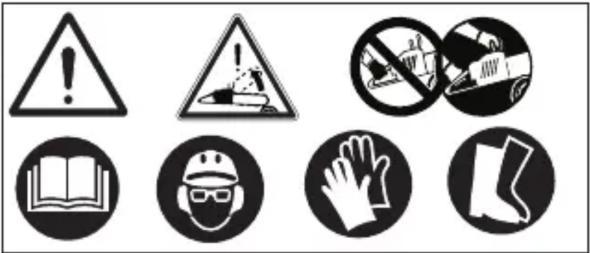
SP 386 - SP 426
SP 466 - SP 526
natural_image
Line drawing of a hand holding a chain with chains and chains attached, no text or symbols present
natural_image
Illustration of hands operating a mechanical device with a black arrow indicating motion (no text or symbols present)
natural_image
Line drawing of hands operating a chain-linking device (no text or symbols present)
natural_image
Line drawing of a person using a chain to cut a tree stump, no text or symbols present
flowchart
graph TD
    A["Brain"] --> B["Rising"]
    A --> C["Picking"]
    A --> D["Person Walking"]
    A --> E["Person Running"]
    A --> F["Person Moving"]
    style A fill:#f9f,stroke:#333
    style B fill:#ccf,stroke:#333
    style C fill:#ccf,stroke:#333
    style D fill:#ccf,stroke:#333
    style E fill:#ccf,stroke:#333
    style F fill:#ccf,stroke:#333
natural_image
Illustration of hands using a chain-linking tool to cut a circular object, no text or symbols present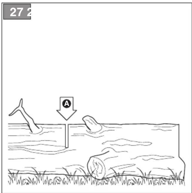
natural_image
Line drawing of a person using a power saw to cut wood in a forest (no text or symbols)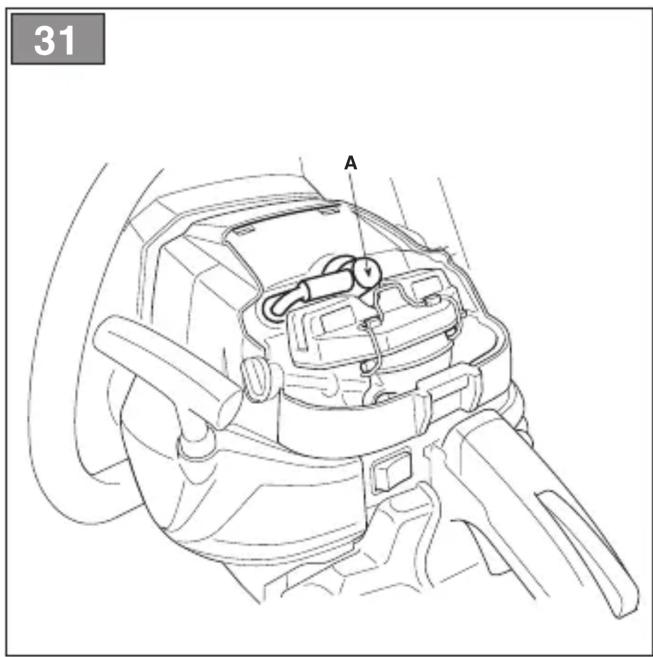
natural_image
Line drawing of a hand using a tool to adjust or install a mechanical component (no text or symbols visible)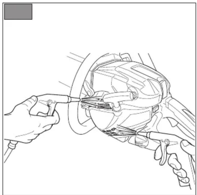
natural_image
Line drawing of hands using a tool to adjust or install a mechanical component (no text or symbols present)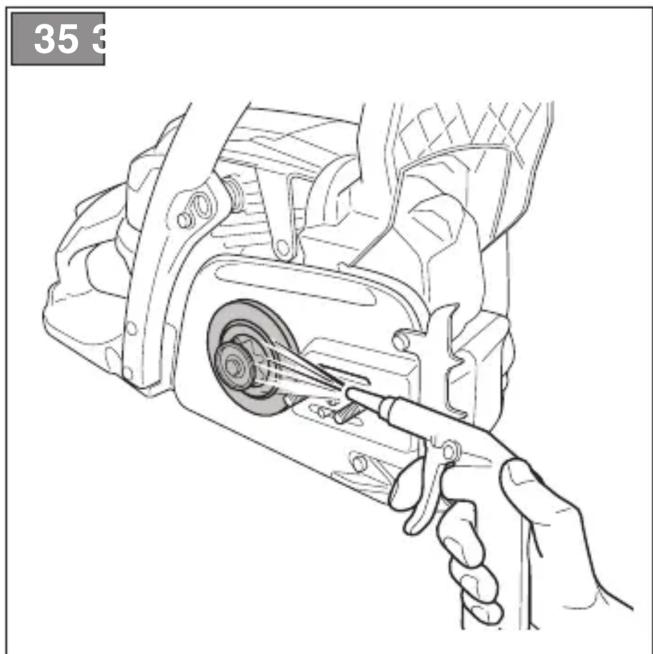
natural_image
Line drawing of a hand using a tool to adjust or install a mechanical component, no text or symbols present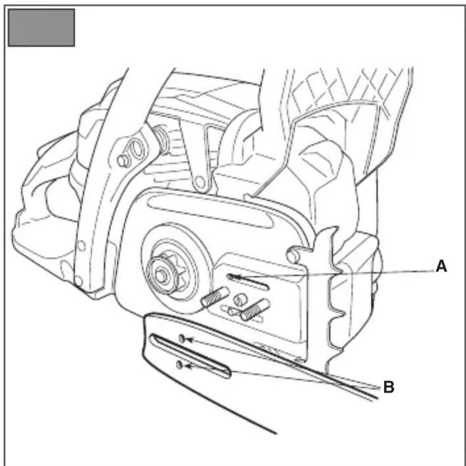
43
44
natural_image
Four identical gray rectangular shapes with V-shaped cutouts and cross marks, arranged horizontally (no text or symbols)- USO DELLA MACCHINA......8
6. USO DELLA MACCHINA
6.4 PRACOVNÍ ČINNOST
3.3 TYPESKILT PÅ PRODUKTET
8.1 SM∅REHULLER I MASKINEN OG I SVÆRDET
T = tomgangsjustering
L = justering for blanding – lav hastighed
- XEIPISTHPIA EΛΕΓΧΟΥ 8
- GENERAL INFORMATION ...... 1
- SAFETY REGULATIONS....2
- GETTING TO KNOW THE MACHINE .... 4
3.1 Description of the machine and planned use.. 4
3.2 Safety signs....5
3.3 Product identification label 5
3.4 Main components....5
- ASSEMBLY 6
4.1 Assembly components....6
4.2 Assembly of the guide bar and toothed chain. 6
- CONTROLS....7
5.1 Engine start/stop switch 7
5.2 Choke lever 7
5.3 Primer control button 7
5.4 Pressure relief valve control (for model SP 526 only) 7
5.5 Throttle trigger lever 7
5.6 Interlock lever 7
5.7 Handle for manual start 7
5.8 Chain brake 7
- USING THE MACHINE 8
6.1 Preparation....8
6.2 Safety checks....9
6.3 Startup 9
6.4 Operation 10
6.5 Advice for operation 12
6.6 Stop.... 12
6.7 After operation.... 13
- ROUTINE MAINTENANCE....13
7.1 General information.... 13
7.2 Preparing the fuel mixture 13
7.3 Refuelling 14
7.4 Topping up the chain oil tank 14
7.5 Cleaning the machine and the engine ..... 14
7.6 Cleaning the chain.... 14
7.7 Chain catcher....15
7.8 Nuts and bolts 15
- EXTRAORDINARY MAINTENANCE 15
8.1 Machine and bar lubrication holes ..... 15
8.2 Cleaning the air filter.... 15
8.3 Clutch Housing....15
8.4 Chain drive sprocket.... 15
8.5 Checking the spark plug 15
8.6 Starter cable 15
8.7 Maintenance of the toothed chain 15
8.8 Guide bar maintenance 16
8.9 Tuning minimum speed 16
8.10 Tuning the carburettor 16
-
STORING THE MACHINE 17
-
HANDLING AND TRANSPORTATION......17
- ASSISTANCE AND REPAIRS 17
- WARRANTY COVERAGE....17
- MAINTENANCE TABLE....18
- CHAIN MAINTENANCE TABLE....19
- PROBLEM IDENTIFICATION.... 19
- ACCESSORIES 20
1. GENERAL INFORMATION
1.1 HOW TO READ THE MANUAL
Some paragraphs in the manual contain important information regarding safety and operation and are emphasized in this manner:
NOTE or IMPORTANT these give details or further information on what has already been said, and aim to prevent damage to the machine.
The symbol highlights danger. Non-compliance with the warning could lead to personal and/or third party injury and or damage.
The paragraphs highlighted in a square with grey spots indicate the optional characteristics not on all models documented in this manual. Check if the characteristic is on this model.
Whenever reference is made to a position on the machine "front", "back", "left" or "right" hand side, this refers to the operator's working position.
1.2 REFERENCES
1.2.1 Figures
The figures in these instructions for use are numbered 1, 2, 3, etc.
Components shown in the figures are marked A, B, C, etc.
A reference to component C in figure 2 is written: "See fig. 2.C" or simply "(Fig. 2.C)".
The figures are given as a guide only. The actual parts may vary from those shown.
1.2.2 Titles
The manual is divided into chapters and paragraphs. The title of paragraph "2.1 Training" is a sub-title of "2. Safety regulations".
References to titles or paragraphs are marked with the abbreviation chap. or par. and the relevant number. Example: "chap. 2" o "par. 2.1".
2. SAFETY REGULATIONS
2.1 TRAINING
⚠️ Become acquainted with the controls and the proper use of the machine. Learn how to stop the machine quickly. Failure to follow the warnings and instructions may result in fire and/or serious injury.
- Never allow children or persons unfamiliar with these instructions to use the machine. Local regulations may restrict the age of the operator.
- Never use the machine if the user is tired or unwell, or has taken medicine, drugs, alcohol or any substances which may slow their reflexes and compromise their judgement.
- Bear in mind that the operator or user is responsible for accidents or unexpected events occurring to other people or their property. It is the user's responsibility to assess the potential risk of the area where work is to be carried out, and to take all the necessary precautions to ensure his own safety and that of others, particularly on slopes or rough, slippery and unstable ground.
- If the machine is sold or lent to others, make sure that the operator looks over the user instructions contained in this manual.
- It takes specific training to use the machine for felling and delimbing.
2.2 PREPARATION
Personal Protective Equipment (PPE)
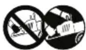
- Always wear slim fitting protective clothing with slash-proof protection, anti-vibration gloves, helmet, protective goggles, half-mask respirator, protective earplugs, cut resistant safety boots with non-slip soles.
- Never wear scarves, shirts, necklaces, bracelets, clothing with flowing parts, laces or ties or any hanging or flapping accessory that could catch in the machine or in any objects or materials in the work area.
- Tie your hair back if it is long.
Internal combustion engines: fuel
⚠️ DANGER! Petrol and the fuel mixture are highly flammable!
- Keep the petrol and fuel mixture in approved fuel containers, in a safe place, away from any naked lights or heat sources.
-
Keep the fuel containers and storage area free of sawdust, branches, leaves, or excessive grease.
-
Keep the containers out of the reach of children.
- Do not smoke when preparing the mixture, when filling or topping up with fuel or when handling the fuel.
- Use a funnel to top up with fuel only in the open air.
- Do not inhale fuel fumes.
- Never remove the tank cap or add fuel whilst the engine is running or when the engine is hot.
- Open the fuel tank slowly to allow the pressure inside to decrease gradually.
- Do not approach the tank opening with a naked flame to check its contents.
- If you have spilt some fuel, do not attempt to start the engine but move the machine away from the area of spillage and avoid creating any source of ignition until the fuel has evaporated and fuel vapours have dissipated.
- Immediately clean up all traces of fuel spilt on the machine or on the ground.
- Replace caps of all fuel tanks and containers securely.
- Never start the machine in the same place in which you refilled it with fuel; the engine must be started in an area at least 3 metres from where you refuelled.
- If fuel is spilt on clothing, change clothing before starting the engine.
2.3 DURING OPERATION
Work Area
- Do not operate the engine in a confined space where dangerous carbon monoxide fumes can develop. All starting operations must be carried out in an open or well ventilated area! Always remember that exhaust fumes are toxic.
- When starting up the machine, do not direct the silencer and therefore the exhaust fumes towards flammable materials.
- Do not use the machine in environments at risk of explosion, in the presence of flammable liquids, gas or powder. Electrical contacts and mechanical friction can generate sparks that can ignite the powder or vapours.
- Work only in daylight or with good artificial light in good visibility conditions.
- Keep persons, children and animals away from the working area. Ask another adult to keep the children under supervision.
- Check that there is anybody within at least 15 metres of the machine's range of action.
-
Where possible, avoid working on wet, slippery ground or in any case on uneven or steep ground that does not guarantee stability for the operator;
-
Pay careful attention to uneven ground hills, dips, slopes, hidden hazards and obstacles than could limit visibility.
- Be very careful near ravines, ditches or embankments.
- Look out for traffic when using the machine near the road.
- To avoid the risk of fire, do not leave the machine with the engine hot on leaves, dry grass or other flammable material.
Behaviour
- When running, the machine must always be firmly held in both hands, (left hand on the front hand grip and the right hand on the rear hand grip, even if the operator is left-handed) at a safe distance from all body parts.
• Always use caution and take on a firm and well balances position. - Avoid using unstable ladders or platforms.
- Avoid working alone or in an isolated place, in case you have to find help after an accident.
- Never run, always walk.
- Make sure the bar does not come into violent contact with foreign bodies/obstacles and try to prevent any material from being hurled by the moving chain. Kickback may occur if the bar comes into contact with an obstacle. Kickback occurs when the tip of the chain comes in contact with an object or when the wood contracts and jams the chain during sawing. This contact with the tip of the chain can cause a rapid backward motion, pushing the guide bar up and towards the operator. This also happens when the chain is jammed along the upper part of the bar. In both cases, kickback can cause the operator to lose control of the chainsaw, leading to serious consequences. To prevent kickbacks, take all appropriate precautions provided below:
– Hold the saw firmly, with the thumbs and fingers around the chainsaw grips, and position your body and arms so that you can resist the force of a kickback.
- Do not fully extend the arms and do not saw above shoulder height.
- Only used the guide bar and chains recommended by the manufacturer.
– Follow the manufacturer's instructions regarding sharpening and maintenance of the chainsaw.
- Avoid exposure to dust and sawdust produced by the chain when cutting.
- Do not touch the engine parts which heat up during use. Burns hazard.
- If something breaks or an accident occurs during work, turn off the engine immediately and move the machine away to prevent further damage; if an accident
occurs with injuries or third parties are injured, carry out the first aid measures most suitable for the situation immediately and contact the medical authorities for any necessary health care. Carefully remove any debris which could cause damage or injury to persons or animals if ignored.
- Prolonged exposure to vibrations can cause injuries and neurovascular disorders (also called "Raynaud's syndrome" or "white hand"), especially to people suffering from circulation disorders. The symptoms appear in the hands, wrists and fingers and are shown through loss of sensitivity, torpor, itching, pain and discolouring of or structural changes to the skin. These effects can be worsened by low ambient temperatures and/or by gripping the hand grips excessively tightly. If the symptoms occur, the length of time the machine is used must be reduced and a doctor consulted.
Use limitations
- Do not use the machine if you are unable to hold it with both hands or keep it steady on your legs while working.
- Never use the machine with damaged, missing or incorrectly positioned guards.
- Don't use the machine if the attachments/tools are not installed in their seats.
- Never disengage, deactivate, remove or tamper with the safety systems/microswitches installed.
- Do not alter the engine adjustments, nor over-run it. If the engine is forced to work with an excessive number of rotations, the risk of personal injury increases.
- Do not strain the machine too much and do not use a small machine for heavy duty work. If you use the right machine, you will reduce the risk of hazards and improve the quality of your work.
Ensure regular maintenance and correct storage to maintain machine safety and high performance levels.
Maintenance
- To reduce the risk of fire, regularly check the machine for oil and/or fuel leaks.
- The noise and vibration levels shown in these instructions are the maximum levels for use of the machine. The use of an unbalanced cutting element, the excessive speed of movement, or the absence of maintenance have a significant influence on noise
emissions and vibrations. Consequently, it is necessary to take preventive steps to eliminate possible damage due to high levels of noise and stress from vibration. Maintain the machine well, wear ear protection devices and take breaks whilst working.
Storage
- Do not store the machine with fuel in the tank in an area where fuel vapours could reach a naked light, a spark or a strong heat source.
- To reduce fire risks, do not leave containers with debris inside a room.
2.5 ENVIRONMENTAL PROTECTION
Safeguarding the environment must be a relevant and priority aspect of machine use, of benefit to the community and the environment we live in.
- Avoid being a disturbance to the neighbourhood. Use this machine at reasonable times of the day only (not early morning or late evening when the noise could cause disturbance).
- A certain amount of chain lubricating oil is released into the environment when the machine is running, so only use biodegradable oils made specifically for this use. Use of a mineral oil or engine oil causes serious damage to the environment.
- Adhere strictly to the local regulations governing the disposal of packaging, oil, fuel, filters, damaged parts or any other element which may have an impact on the environment; this waste should not be disposed of along with standard household waste, but must be disposed of separately and sent to special waste disposal facilities for handling and recycling.
- Comply with local regulations for the disposal of waste materials
- When the machine is withdrawn from service, do not dispose of it in the environment, but take it to a waste disposal facility in accordance with the local regulations in force.
3. GETTING TO KNOW THE MACHINE
3.1 DESCRIPTION OF THE MACHINE AND PLANNED USE
This machine is a forestry tool and precisely a chainsaw designed for forestry work.
The machine is essentially composed of a 2-stroke internal combustion engine, fuelled by an air-cooled oil-petrol mix, and a guide bar that drives the power from the engine to the toothed chain that acts as a fully fledged saw. The movement is transmitted from the engine to the chain by a centrifugal clutch that prevents the chain from moving when the engine is running at minimum speed.
The operator is able to operate the machine with two hands, using the front and rear hand grips, and use the main controls, always remaining at a safe distance from the cutting means.
3.1.1 Intended use
This machine was designed and manufactured for:
– felling, bucking and delimbing trees with dimensions suitable for the length of the guide bar or wooden objects with the same characteristics;
- use by one operator.
3.1.2 Improper use
Any other usage not in keeping with the above-mentioned ones may be hazardous and harm persons and/or damage things. Examples of improper use may include, but are not limited to:
- trimming hedges;
– carving operations;
– sectioning pallets, crates and various packing materials;
– sectioning furniture or other materials with nails, screws or other metal components;
– butchering meat;
– using the machine to cut materials other than wood (plastic materials, building materials);
– using the machine to lift, move or split objects;
– using the machine while fastened to fixed supports;
– using cutting means other than those found in the "Technical Data" table. Serious injury and wound hazard.
– use of the machine by more than one person.
IMPORTANT Improper use of the machine
will invalidate the warranty, relieve the Manufacturer from all liability, and the user will consequently be liable for all and any damage or injury to himself or others.
3.1.3 User types
This machine is intended for use by consumers, i.e. non-professional operators. The machine is intended for "DIY" use only.
3.2 SAFETY SIGNS
The machine has various symbols on it (Fig. 2). They are used to remind the operator of the behaviour to follow to use it with the necessary attention and caution.
Meaning of symbols:

WARNING! DANGER! Failure to use this machine correctly can be hazardous for oneself and others

WARNING! Read the instruction manual before using the machine.

Anyone operating the machine under normal conditions for continuous daily use may be exposed to a noise level equal to or exceeding 85 dB (A). Wear ear protectors, safety goggles and a protective helmet.

Wear gloves and safety boots!


BEWARE OF KICKBACK!
Kickback is the rapid and uncontrollable backward motion of the chainsaw in the direction of the operator. Always work in complete safety. Use chains with safety links that limit kickback.
Never hold the machine with one hand! Hold the machine fast with both hands to control the machine and reduce the risk of kickback.
IMPORTANT Any damaged or illegible decals must be replaced. Order replacement decals from an Authorised Service Centre.
3.3 PRODUCT IDENTIFICATION LABEL
The product identification label provides the following data (Fig. 1):
- Sound power level
- Conformity marking
- Year of manufacture
- Type of machine
- Serial number
- Name and address of Manufacturer
- Article code
- Emission number
Write the identification data of the machine in the specific space on the label on the back of the cover page.
IMPORTANT Quote the information on the product identification label whenever you contact an Authorised Service Centre.
IMPORTANT The example of the Declaration of Conformity is provided on the last pages of the manual.
3.4 MAIN COMPONENTS
The machine is made up of the following main components (Fig. 1):
A. Engine: supplies the drive power to the cutting means.
B. Front hand grip: support hand grip located on the front of the chainsaw. This should be grasped using the left hand.
C. Rear hand grip: support hand grip located on the rear of the chainsaw. This should be grasped using the right hand. This hand grip is fitted with the main throttle controls.
D. Front hand guard: protection device seated between the front hand grip and the toothed chain, to protect the hand against injuries should it slip off the hand grip. This guard is used as a device to trigger the chain brake (par. 5.7).
E. Rear hand guard: protection device seated in the lower right section of the rear hand grip, to protect the hand from the chainsaw should it break or disconnect from the guide bar.
F. Guide bar: supports and guides the toothed chain.
G. Toothed chain: cutting element, consisting of drive links fitted with small blades called "teeth" and side connections held in place by rivets.
H. Chain restraint pin: safety device that prevents uncontrolled movements of the toothed chain should it break or slacken.
I. Spiked bumper: device installed opposite the guide bar assembly point acting as a pivot when it comes into contact with a tree or trunk.
J. Spiked bumper guard: spiked bumper cover to be fitted during handling, transportation or storage of the machine. This guard must be removed when using the machine.
K. Bar cover guard: chainsaw cover on the guide bar to be fitted during handling, transportation or storage of the machine.
4. ASSEMBLY
IMPORTANT The safety regulations to follow during machine use are described in Chapter 2. Strictly comply with these instructions to avoid serious risks or hazards.
For storage and transport purposes, some components of the machine are not installed in the factory and have to be assembled after unpacking. Follow the instructions below.
⚠ Unpacking and completing the assembly should be done on a flat and stable surface, with enough space for machine handling and its packaging, always making use of suitable equipment. Do not use the machine until all the instructions provided in the "ASSEMBLY" section have been carried out.
4.1 ASSEMBLY COMPONENTS
The packaging holds the components needed for assembly as listed in the table below:
| Description |
| Guide bar fitted with bar cover |
| Toothed chain |
| Key (housed below the lower section of the machine) (Fig. 1.M) |
| Cutting chain sharpening filing tool |
| Documentation |
4.1.1 Unpacking
-
Carefully open the packaging, paying attention not to lose components.
-
Consult the documentation in the box, including these instructions.
- Remove all the unassembled parts from the box.
- Remove the machine from the box.
- Dispose of the box and packaging in compliance with local regulations.
4.2 ASSEMBLY OF THE GUIDE BAR AND TOOTHED CHAIN
Always wear heavy duty gloves when handling the bar and chain. Mount the bar and chain very carefully so as not to impair the safety and efficiency of the machine. If in doubt, contact your dealer.
⚠ Perform all operations with the engine off.
Before assembling the bar, check that the chain brake is not engaged (par. 5.7).
- Loosen all the nuts (Fig. 3.A) and remove the clutch cover (Fig. 3.B) to get to the drive sprocket and the point where the bar is fitted.
- Remove the plastic spacer (Fig. 3.C); this spacer must be used exclusively when transporting the machine in its packaging and must not be used at any other time.
- Mount the bar (Fig. 4.A) by inserting the stud bolts (Fig. 4.B) in the groove (Fig. 4.C) and push it towards the back of the machine body.
- Mount the chain (Fig. 5.A) around the drive sprocket (Fig. 5.B) and along the bar guide (Fig. 5.C), making sure it is fitted in the right direction (Fig. 5.D).
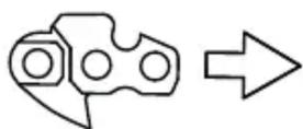
Direction in which
the chain runs
If the tip of the bar is equipped with a nose sprocket, make sure the drive links are correctly inserted in the sprocket rims (Fig. 6).
- Check that chain tension adjuster pin (Fig. 7.A) is fitted properly into the hole on the bar; if it isn't, turn the chain tension adjuster screw using a screwdriver (Fig. 7.B), until the pin is completely inserted.
- Refit the guard without fully tightening the nuts.
- Turn the chain tension adjuster screw (Fig. 8.A) to achieve the desired tension.
- Raise the bar and tighten the guard nuts securely using the wrench (Fig. 9).
4.2.1 Checking the chain tension
Check the chain tension.
The tension is correct when the drive links do not slip out of the chain guides if you hold the chain in the middle of the bar (Fig. 10).
5. CONTROLS
5.1 ENGINE START/STOP SWITCH
Used to start and stop the engine (Fig. 11.C).

The engine can start and run.

The engine stops.
After pressing the stop switch, the switch automatically returns to the start position "I"
5.2 CHOKE LEVER
Used to turn on the engine when cold. The choke control has two positions:

Position A (Fig. 11.A) - the choke is not engaged (normal operations and warm start)..

Position B (Fig. 11.B) - the choke is engaged (for a cold start).
5.3 PRIMER CONTROL BUTTON

Press the rubber button of the primer (Fig. 12.A) to inject fuel into the carburettor intake manifold to facilitate startup when the engine is cold.
5.4 PRESSURE RELIEF VALVE CONTROL (FOR MODEL SP 526 ONLY)
Press the valve (Fig. 13.E) to reduce the compression of the cylinder and to start the machine more easily.
5.5 THROTTLE TRIGGER LEVER
Used to regulate the chain speed.
The throttle trigger lever (Fig. 12.B) can only be used if the throttle interlock lever is pressed simultaneously (Fig. 12.C).
The correct running speed will be achieved by pressing the throttle trigger lever (Fig. 12.B) as far as possible.
5.6 INTERLOCK LEVER
The interlock lever (Fig. 12.C) allows the throttle trigger lever to be used (Fig. 12.B).
5.7 HANDLE FOR MANUAL START
For manual engine start-up (Fig. 11.D).
5.8 CHAIN BRAKE
This is a safety braking system that blocks the chain movement when kickback occurs during cutting. Kickbacks occur following an irregular contact of the tip of the bar with a rapid upward movement of the bar that causes the hand to strike the front guard (Fig. 1.D). It must be manually released to disengage the chain brake.

Chain brake disengaged. This is achieved when the front hand guard (Fig. 1.D) is pulled all the way back towards the front hand grip until it clicks into position.

Chain brake engaged. This is achieved when the front hand guard (Fig. 1.D) is pushed all the way forward.
Do not use the machine if the chain brake does not function correctly and have it inspected by your dealer.
6. USING THE MACHINE
IMPORTANT The safety regulations to follow during machine use are described in Chapter 2. Strictly comply with these instructions to avoid serious risks or hazards.
6.1 PREPARATION
Before starting to work, it is necessary to carry out several checks and operations to ensure you can work efficiently and in maximum safety.
IMPORTANT The machine is supplied with the fuel and chain lubrication oil tanks empty.
6.1.1 Refuelling
Fill with fuel before using the machine. For preparing the mixture, refuelling methods and precautionsent see paragraph 7.3.
6.1.2 Filling with chain lubrication oil
Fill with chain lubrication oil before using the machine. For oil filling methods and precautionsent see paragraph 7.4.
6.1.3 Checking the chain tension
⚠ Perform all operations with the engine off.
Always wear heavy duty gloves.
Check the chain tension.
The tension is correct when the drive links do not slip out of the chain guides if you hold the chain in the middle of the bar (Fig. 10).
To adjust the chain tension:
- loosen the cover nuts, using the supplied wrench;
- turn the chain tension adjuster screw (Fig. 8.A) to achieve the desired tension;
- raise the bar and tighten the guard nuts securely using the wrench (Fig. 9).
⚠️ Never work with the chain loose as it can be hazardous if the chain slips out of the bar guides.
IMPORTANT During the first period of use it must be checked more frequently due to settling of the chain.
6.1.4 Preparing the machine before starting work
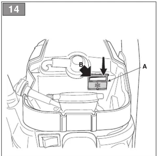
- Anti-freeze device
When using the chainsaw at temperatures under +5°C, it is necessary to change the anti-freeze device settings before starting the machine to prevent ice from forming inside the carburettor, which will result in a loss in engine power or erratic engine performance.
The machine is equipped with an air vent hatch on the cylinder lid, to allow warm air flow to the engine.
In normal operating conditions (temperatures above +5°C), use the machine in standard operating mode, i.e. using factory default settings.
To switch from "Normal" mode to "Anti-freeze" mode (and vice versa):
- stop the machine (par. 6.6);
- remove the air filter cover and the air filter (par. 8.2);
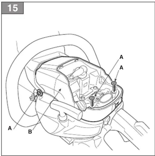
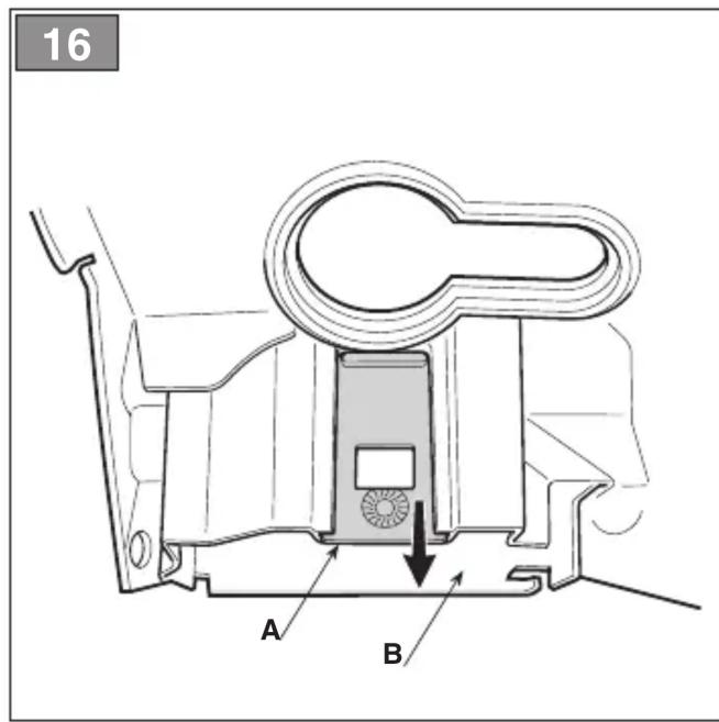
– remove the anti-freeze cap from its housing to the right of the cylinder cover (Fig. 14.A); - Turn the anti-freeze cap so that the «SNOW» symbol is facing downwards to leave the air vent hatch open (Fig. 14.B);
3.a on models SP386, SP 426:
3.b on models SP466, SP 526:
– unscrew the screws which secure the cylinder cover in place (Fig. 15.A) (2 screws inside and one outside) and remove the cylinder cover. (Fig. 15.B);
– remove the anti-freeze cap from its housing (Fig. 16.A), in the centre and at the back of the cylinder cover (Fig. 16.B);
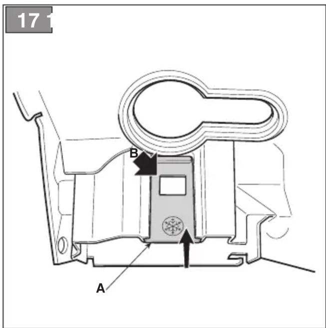
– Turn the anti-freeze cap so that the «SNOW» symbol is facing downwards (Fig. 17.A) to leave the air vent hatch open (Fig. 17.B);
- remount the cylinder cover.
- remount the air filter cover and the relative cover (par. 8.2).
NOTE If the machine is used in anti-freeze mode at temperatures above +5°C, this may cause difficulties when starting the engine and during use due to the incorrect engine speed. Always check that the machine is switched to standard mode (anti-freeze cap with the «SUN» symbol facing sideways and the air vent hatch closed) if there is no danger of ice forming.
6.2 SAFETY CHECKS
Run the following safety checks and check that the results correspond to those outlined on the tables.

Always carry out the safety
checks before use.

Always carry out daily inspection before
use and after dropping or other impacts to identify significant damage or defect.
6.2.1 General check
| Object Result | |
| Hand grips and guards (Fig. 1.B - 1.E) | Clean, dry, without traces of oil and grease, and fixed correctly and firmly to the machine. |
| Screws on the machine and bar | Correctly tightened (not loose) |
| Guide bar (Fig. 1.F) Properly installed. | |
| Chain (Fig. 1.G) Sharp, | not damaged or worn, mounted and tensioned correctly. |
| Air filter (Fig. 38.B) Clean | |
| Electric cables and spark plug cable | Undamaged to prevent sparks. |
| Spark plug cap (Fig. 31.A) | Undamaged and fitted correctly on the spark plug |
6.2.2 Machine operating test
| Action Result | |
| Start the machine (par. 6.3) | The chain (Fig. 1.G) must not move when the engine is running idle.⚠ Do not use the machine if the chain moves when the engine is running idle; in this case, contact your dealer. |
| Engage the throttle trigger lever (Fig. 12.B) and the interlock lever simultaneously (Fig. 12.C). | The levers must move freely and not be forced. The chain moves. |
| Action Result | |
| Release the throttle trigger lever (Fig. 12.B) and the interlock lever (Fig. 12.C). | The levers must return automatically and rapidly to the neutral position, the engine must return to running idle and the chain must be stationary. |
| Engage the throttle trigger lever (without pressing the interlock lever) (Fig. 12.B). | The throttle trigger lever remains blocked. |
| Press the engine start/stop switch (Fig. 11.C) | The switch must move easily from one position to another and must return automatically to the start position when released. |
| CHECKING THE CHAIN BRAKE1. Start the machine (par. 6.3):2. Grasp the hand grips firmly with both hands.3. Use the throttle lever to keep the chain moving, push the front hand guard forwards using the back of your left hand;(par. 5.7). | 3. The chain must stop moving immediately.When the chain has stopped, immediately release the throttle trigger lever and disengage the chain brake (par. 5.7). |

If any of the results fails to match
the instructions provided in the following table, do not use the machine! Take it to an Authorised Service Centre to be checked and repaired if necessary.
6.3 STARTUP
IMPORTANT
A label (Fig. 2) is placed on the
machine that summarizes the start up main steps.
The label is a quick guide and it does not replace the procedures specified below.
Before starting the machine:
- Place the machine firmly on the ground.
- Remove the bar cover guard (Fig. 1.K) and the spiked bumper guard (Fig. 1.J) (if fitted).
-
Make sure the bar and the chain are not touching the ground or any other object.
-
Make sure the chain brake is engaged (par. 5.7).
IMPORTANT To avoid breaking the starter cable, do not pull the whole length of it or let it slide along the edge of the cable guide hole. Release the starter hand grip gradually, to prevent it flying back uncontrollably.
IMPORTANT Never wind the starter cable around your hand.
⚠️ Never start the chainsaw by holding on to the starter cable and allowing it to fall. This is an extremely dangerous method as you lose complete control over the machine and the chain.
NOTE The switch is always in the start position (par. 5.1).
6.3.1 Startup from cold
A "cold" start of the engine means starting it after at least 5 minutes from when it was switched off or after refuelling.
- Engage the choke by turning the lever to position «B» (Fig. 11.B).
- Press the primer device button (Fig. 12.A) 6 times to prime the carburettor.
- For model SP 526 only: Press the pressure relief valve (Fig. 13.E).
NOTE Immediately after the engine starting, the valve automatically returns to its original position.
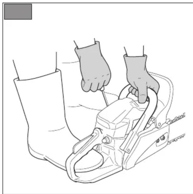
- Hold the machine firmly on the ground with your hand on the front hand grip and your foot in the rear hand grip, to avoid losing control during starting (Fig. 18).
⚠️ If the machine is not held firmly, the force of the engine could cause the user to lose his balance or direct the bar towards him or an obstacle.
- Pull the starter hand grip slowly for 10 - 15 cm until you feel some resistance, then pull it 4 times until you hear the engine start to tick over. Engine will not start at this stage.
IMPORTANT Do not pull the starter hand grip more than 4 times.
-
Disengage the choke (Fig. 11.A) by turning the lever to position «A».
-
Pull the starter grip again until the engine starts as normal.
- When the engine has started, simultaneously activate the throttle trigger lever (Fig. 12.B) and the interlock lever briefly (Fig. 12.C) to cancel fast tick over. Allow the engine to run idle for 10-15 seconds.
- Disengage the chain brake (par. 5.7).
IMPORTANT Do not let the engine run at high speed with the chain brake engaged, as this could cause overheating and damage to the clutch.
- Let the engine run idle for at least 1 minute before using the machine.
IMPORTANT If the starter hand grip is pulled repeatedly with the choke engaged, it may flood the engine and make starting difficult. "If the engine floods (see paragraph 15.5).
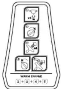
6.3.2 Warm start
When hot starting (immediately after stopping the engine):
-
Press the primer device button (Fig. 12.A) 6 times to prime the carburettor.
-
For model SP 526 only: Press the pressure relief valve (Fig. 13.E).
NOTE Immediately after the engine starting, the valve automatically returns to its original position.
- Engage the choke (position «B» - par. 5.2) and then immediately disengage again (position «A» - par. 5.2); this will engage the fast tick over.
- Follow points 4 - 7 - 8 - 9 in the previous procedure (par. 6.3.1).
6.4 OPERATION
Before felling or delimbing for the first time, make sure: - you have been specifically trained to use this type of equipment; - you have carefully read the safety regulations and user instructions contained in this manual; - you practise first on logs on the ground or attached to trestles, in order to get familiar with the machine and the most suitable cutting techniques.
To operate with the machine proceed as described below:
• Always disengage the chain brake, before using the throttle control.
- The machine must always be firmly held in both hands, with the left hand on the front hand grip and the right hand on the rear hand grip, even if the operator is left handed.

Stop the machine immediately e chain stops during sawing.
6.4.1 Checks to be conducted whilst working
6.4.1.a Checking the chain tension
The chain tends to stretch gradually as you work, so you need to check its tension frequently (par. 6.1.3).
6.4.1.b Checking the oil delivery
IMPORTANT Never use the machine without lubrication! The oil tank may also be empty every time the fuel runs out. Make sure you top up the oil tank every time you refuel the machine (par. 7.4).

Make sure the bar and the chain are place when you check the oil delivery.
Start the engine (par. 6.3), keep it running at medium power and check if the chain oil is delivered as shown in (Fig. 19).
You can adjust the chain oil flow using a screwdriver on the pump adjuster screw (Fig. 20.A) which is on the bottom of the machine.
This is the symbol that identifies the oil pump regulator:

Use a screwdriver to turn it to the "+" position to increase the oil flow to the chain; turn it to the "-" position to decrease the flow.
6.4.2 Work techniques
6.4.2.a Delimbing a tree
⚠️ Make sure there is nothing or anybody in the area where the branches will fall.
- Stand opposite the branch you want to cut.
- Start cutting lower branches followed by the higher ones.
- Cut downwards to prevent the bar from getting jammed (Fig. 21).
6.4.2.b Felling a tree
IMPORTANT Where two or more persons are working together on felling and bucking operations, such operations must be performed in separate areas at a distance from each other of at least 2.5 times the height of the tree being felled. Do not fell trees if this involves risks of injuring people, coming into contact with a power line or causing any form of damage. If the tree should come into contact with a main power line, report the incident immediately to the network provider.
Before commencing the felling operations: - it is necessary to evaluate the natural inclination of the tree, the part where the branches are larger and the wind direction, to assess how the tree will actually fall; - remove any dirt, stones, pieces of bark, nails, metal staples and wire; - clear the area around the tree and find a stable place to stand; - plan obstacle-free escape routes at a 45^ angle back and away from the direction of the fall (Fig. 22) which allow the operator to escape to a safe zone, approximately 2.5 times the height of the tree being felled; - Stand upstream of the land onto which the tree will probably roll or fall over after felling.
- Performing a face notch
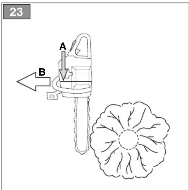
- Following the directional marks on the chainsaw (Fig. 23.A), point towards a target on the ground in the direction in which you intend to fell the tree (Fig. 23.B).
- Stand to the right of the tree, behind the chainsaw.
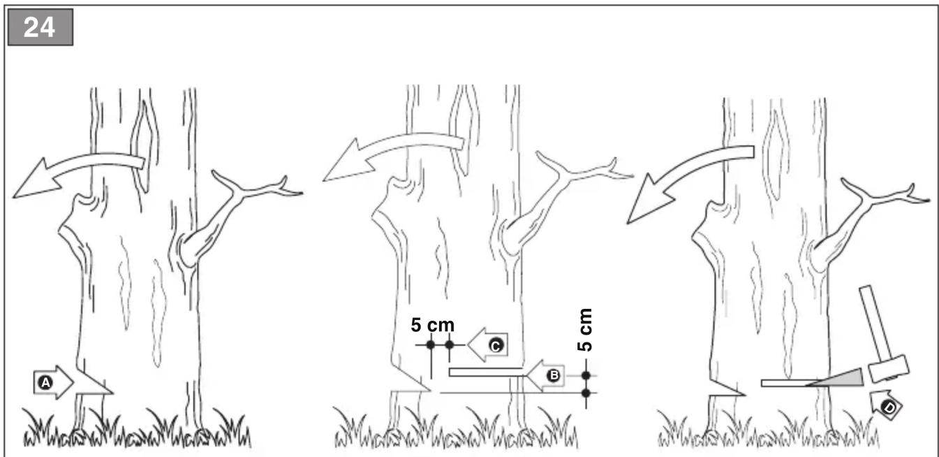
- Saw a horizontal face notch to 1/3 of the diameter of the tree, perpendicular to the direction in which it will fall (Fig. 24.A).
- Felling back cut
- Perform the felling back cut at least 5 cm higher than the horizontal face notch (Fig. 24.B).
-
Perform the felling back cut leaving sufficient wood to act as a "hinge" (Fig. 24.C). The hinge wood will prevent the tree from twisting and falling in the wrong direction. Do not cut through the hinge.
-
Reduce the thickness of this hinge without pulling out the bar, until the tree falls.
- If there is any risk of the tree not falling in the desired direction, or that it might lose its balance moving backwards and bending the toothed chain, stop cutting before completing the felling back cut and use some wooden, plastic or aluminium wedges (Fig. 24.D) to open the cut. Force the tree to fall along the desired line by hitting the wedges with a sledge hammer.
- When the tree starts to fall, it is necessary to withdraw the machine from the cut, switch it off (par. 6.6), lie it on the ground and take the foreseen exit route. Beware of falling branches and pay attention where you put your feet.
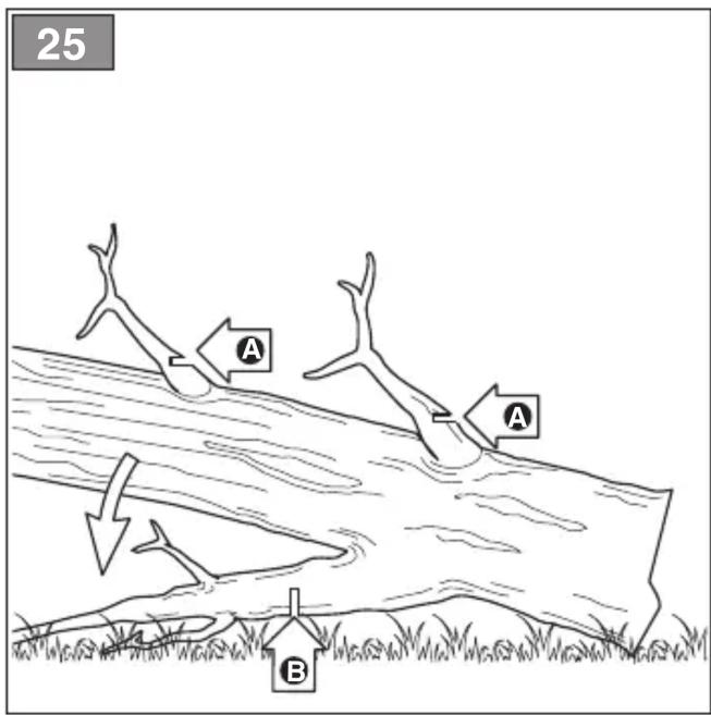
6.4.2.c Limbing tree branches
Limbing means removing the branches from a felled tree.
⚠️ Be careful of where the branches are lying on the ground, the risk of them being under tension, the direction the branch may go during cutting and the risk of the tree being unstable after the branch has been cut.
When limbing, it is necessary to leave the lower, larger branches to support the trunk on the ground. Remove the small branches with a single blow (Fig. 25.A).
It is recommended to cut the tensioned branches working from the bottom upwards to prevent the chainsaw from bending (Fig. 25.B).
6.4.2.d Bucking the trunk
Bucking means sawing a tree trunk into logs.
It is essential to make sure your feet are positioned firmly on the ground, and your weight is distributed equally on both feet. If possible, it is recommended to raise and support the trunk using branches, logs or blocks of wood.
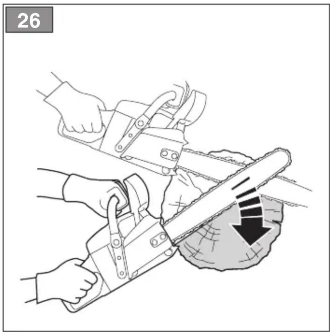
It is easier to saw a log using the spiked bumper (Fig. 1.1):
- plant the spiked bumper into the log and use it as a pivot. Cut with an arched motion to make the bar penetrate the wood (Fig. 26);
- repeat several times if necessary, changing the point where you plant the spiked bumper.
- Trunk lying on the ground
When the entire trunk is lying on the ground, it is bucked from the top down (overbucking) (Fig. 27.A).
- Cut up to half the diameter, roll the log over and finish sawing on the other side.
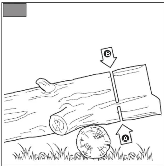
- Trunk resting on one end only
When the trunk is resting on one end only: - saw through 1/3 of the diameter from the bottom up (underbucking) (Fig. 28.A); - then perform the final cut, overbucking to reach the first cut (Fig. 28.B).
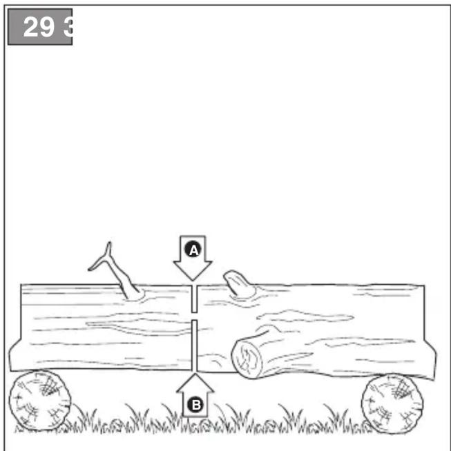
- Trunk resting on both ends
When the trunk is resting on both ends: – saw through 1/3 of the diameter from the top down (overbucking) (Fig. 29.A); – then perform the final cut, underbucking the lower 2/3 to reach the first cut (Fig. 29.B).
- Sloping trunk
Always stand upstream when bucking a sloping trunk (Fig. 30).
During the operation, to maintain control when the cut is almost complete, reduce the bucking pressure without removing removing your hands from the machine hand grips. Take all necessary precautions to prevent the machine from coming into contact with the ground.
NOTE Avoid using the machine at full power for the first 6-8 working hours.
IMPORTANT Stop the machine (par. 6.6) when moving between work areas.
6.6 STOP
To stop the machine:
- Release the throttle trigger lever (Fig. 12.B) and allow the engine to run at idle speed for a few seconds.
- Turn the switch (Fig. 11.C) to the «O» position.
- Wait until the chain is stationary.
When you have reduced speed to a minimum, it will take a few seconds for the chain to stop.
The engine may be very warm immediately after it is shut off. Do not touch. The engine can cause burn injuries.
6.7 AFTER OPERATION
- Remove the spark plug cap (Fig. 31.A).
- Mount the bar cover.
- Allow the machine to cool down.
- Loosen the rod fastening nuts to reduce chain tension.
- Carefully remove any dust and debris and remove all traces of sawdust or oil deposits from the chain. (par. 7.5, par. 7.6).
- Check there are no loose or damaged components. If necessary, replace the damaged components and tighten any screws and loose bolts.
IMPORTANT Stop the machine (par. 6.6), remove the spark plug cap (Fig. 31.A) and mount the bar cover whenever the machine is unused or left unattended.
7. ROUTINE MAINTENANCE
7.1 GENERAL INFORMATION
IMPORTANT The safety regulations to follow during machine use are described in Chapter 2. Strictly comply with these instructions to avoid serious risks or hazards.

Before conducting any
inspections, cleaning or maintenance/adjustment interventions on the machine:
- Stop the machine;
- Wait until the chain is stationary;
- Apply the bar cover, except when working directly on the chain or bar itself.
- Remove the spark plug cap (Fig. 31.A);
- Wait until the engine is sufficiently cold;
- Read the relevant instructions;
- Use suitable clothing, protective gloves and goggles;
- The frequency and types of maintenance are summarised in the "Maintenance Table" (see chapter 12). The table will help you maintain your machine's safety and performance. It summarises the main interventions to be made and the frequency applicable to each of them. Carry out the relevant intervention according to the first deadline.
- The use of non-genuine spare parts and attachments could adversely affect machine operation and safety. The manufacturer shall decline all liability in the event of injuries or damages caused by such parts.
• Genuine spare parts are supplied by Authorized Service Centres and Dealers.
- Never use the machine with worn or damaged parts. Damaged parts are to be replaced and never repaired.
IMPORTANT All the maintenance and adjustment operations not described herein must be carried out by your dealer or Authorised Service Centre.
7.2 PREPARING THE FUEL MIXTURE
This machine has a two-stroke engine which requires a mixture of petrol and lubricating oil.
IMPORTANT Using petrol alone will damage the engine and will void the warranty.
IMPORTANT Only use quality fuels and oils to maintain high performance and guarantee the duration of the mechanical parts over time.
7.2.1 Petrol characteristics
Only use unleaded petrol with an octane rating of at least 90.
IMPORTANT Unleaded petrol tends to create deposits in the container if stored for more than 2 months. Always use fresh petrol!
7.2.2 Oil characteristics
Only use top quality synthetic oil that is specifically for two-stroke engines, of JASO FC minimum specification.
Your dealer can provide you with oils which have been specifically developed for this type of engine, and which are capable of guaranteeing a high level of protection. The use of these oils makes it possible to prepare a 2.5% mixture, consisting of 1 part oil to 40 parts petrol.
7.2.3 Preparation and storage of the fuel mixture
The chart indicates the amount of petrol and oil to use to prepare the fuel mixture.
| Petrol 2-stroke | synthetic oil |
| litres litres | |
| 1 | 0.025 |
| 2 | 0.050 |
| 3 | 0.075 |
| 5 0.125 | |
| 10 0.250 |
To prepare the fuel mixture:
- Place about half the amount of petrol in a homologated tank.
- Add all the oil.
- Add the rest of the petrol.
- Close the top and shake well.
IMPORTANT The fuel mixture tends to age. Do not prepare excessive amounts of the fuel mixture to avoid the formation of deposits.
IMPORTANT Keep the petrol and fuel mixture containers separate and easily identifiable to avoid the mistake of using one in place of the other.
IMPORTANT Periodically clean the petrol and fuel mixture containers to remove any deposits.
7.3 REFUELLING
⚠️ Refuelling must take place when the machine is switched off and the spark plug cap removed.
Before refuelling:
- Shake the fuel mixture container well.
- Place the machine on a flat stable surface, with the fuel tank cap facing upwards.
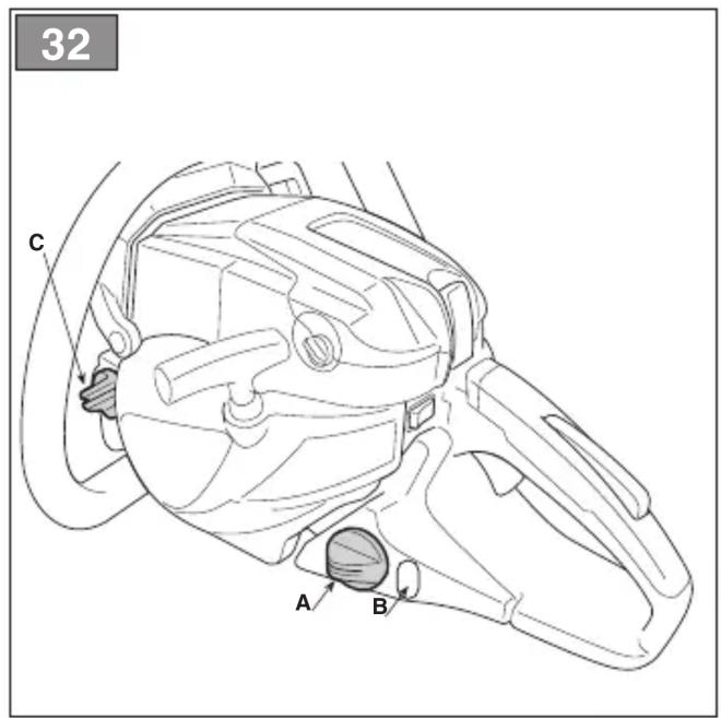
NOTE The following symbol is found near the fuel tank cap (Fig.32.A):

Fuel mixture tank
- Clean the fuel tank cap and the surrounding area to prevent any dirt from entering the tank during refuelling.
- Open the fuel tank cap carefully to allow the pressure inside to decrease gradually.
- Use a funnel to refill and avoid filling the tank to the brim.
NOTE When using the machine, the fuel level can be checked through the tank window (Fig. 32.B).
7.4 TOPPING UP THE CHAIN OIL TANK
NOTE The following symbol is found near the chain oil tank cap (Fig. 32.C):

Chain oil tank
IMPORTANT Only use chainsaw oil or adhesive oil for chainsaws. Do not use oil containing impurities so as not to block the oil filter and to prevent irreparable damage to the oil pump.
It is essential that you use good quality oil to lubricate the cutting parts effectively. Used or poor quality oil does not guarantee good lubrication and reduces the working life of the chain and bar.
- It is always worth topping up the oil tank completely (using a funnel) every time you refuel. Since the oil tank capacity is enough to guarantee that the fuel runs out first, you will avoid the risk of operating the machine without lubricant.
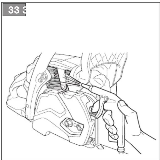
7.5 CLEANING THE MACHINE AND THE ENGINE
After every work session, clean the machine thoroughly to remove all dust and debris.
- To reduce fire hazards:
- keep the machine and, in particular, the engine and muffler zone free of sawdust, branches, leaves, or excessive grease;
- use compressed air to clean the cylinder fins on a regular basis (Fig. 33).
• To avoid overheating and damage to the engine:
– always keep the cooling air vent (Fig. 34) clean and free of sawdust and debris.
- Keep the clutch bell free of sawdust and debris (Fig. 35), removing the clutch (par. 4.2) and remounting it correctly afterwards. Have your dealer check the greasing of the internal bearing approximately every 30 hours.
7.6 CLEANING THE CHAIN
Remove any traces of sawdust or oil deposits from the chain every time it is used.
If there is excessive dirt or resin build-up, disassemble the chain and place it in a container with a specific cleanser for a few
hours. Then rinse with clean water and treat with a suitable anticorrosive spray, before reassembling on the machine.
7.7 CHAIN CATCHER
Before use, always check the condition of the chain catcher (Fig.1.H) beforehand and replace it if damaged.
7.8 NUTS AND BOLTS
- Before use, always check that all nuts and bolts are securely tightened to be sure the machine is in safe working condition.
- Before use, always check that the hand grips are firmly fastened in place.
8. EXTRAORDINARY MAINTENANCE
8.1 MACHINE AND BAR LUBRICATION HOLES
Before daily use, remove the clutch casing (par. 4.2), remove the bar and check that neither the machine lubrication (Fig. 36.A) nor the guide bar (Fig. 36.B) holes are clogged.
8.2 CLEANING THE AIR FILTER
IMPORTANT Cleaning the air filter is essential to guarantee the efficiency and durability of the machine. Do not work with a damaged filter or without a filter, as this could permanently damage the engine.
It must be cleaned after every 8-10 working hours.
Clean the filter as follows:
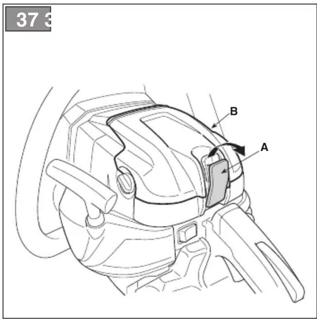
- Release the tab (Fig. 37.A) and remove the cover (Fig. 37.B).
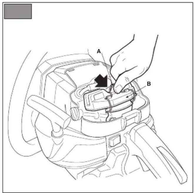
- Press the metal air filter block until it attaches with a click (Fig. 38.A).
- Remove the air filter (Fig. 38.B), tap it gently to remove the dirt and clean using a soft brush.
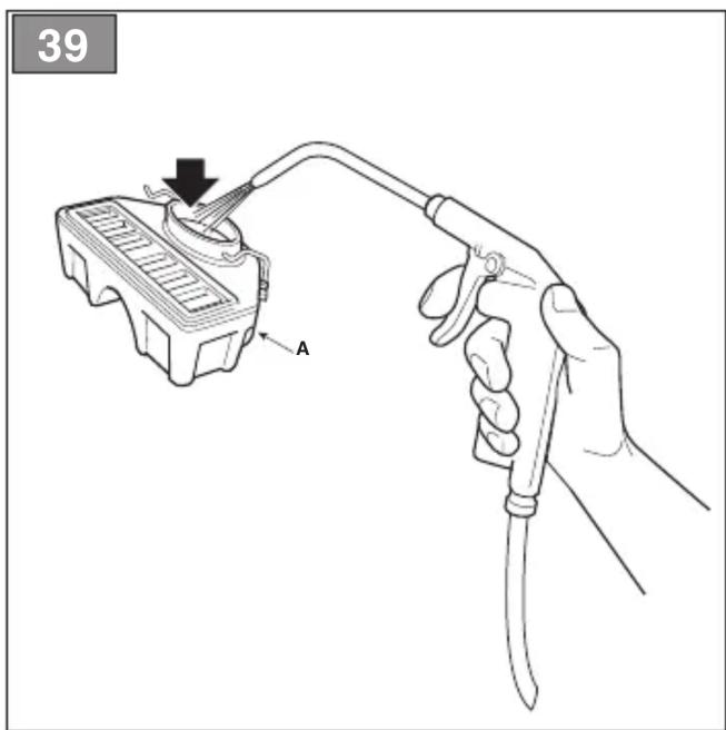
- If the filter is completely clogged, wash with clean petrol. If you are using compressed air, aim the jet so that it blows from the inside towards the outside (Fig. 39.A).
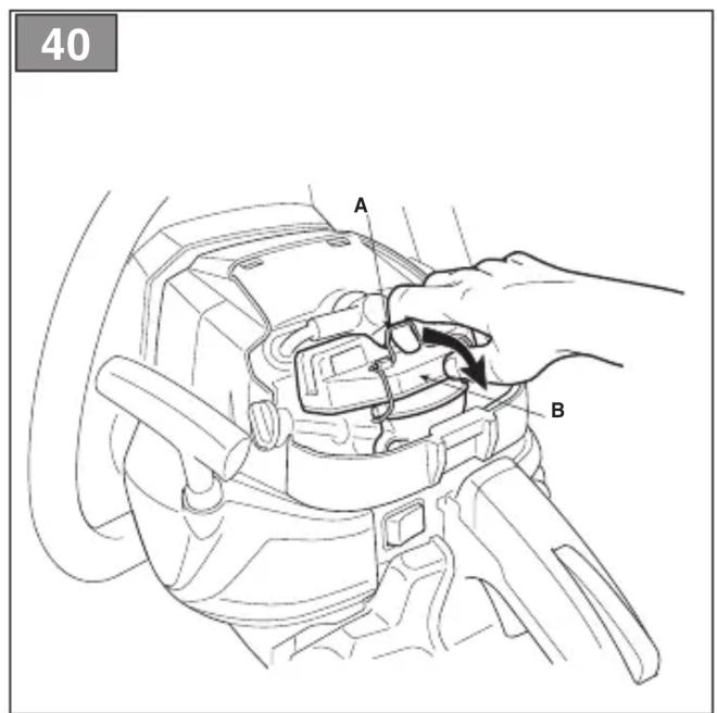
- Replace the filter (Fig. 40.B), pull the metal block (Fig. 40.A) until it clicks the filter into position.
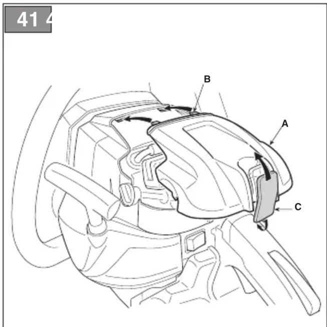
- Remount the casing (Fig. 41.A) making sure that all the parts are
positioned correctly in their housings on the cylinder cover (Fig. 41.B).
- Insert the lower section of the tab and press the top part until it clicks into place (Fig. 41.C).
8.3 CLUTCH HOUSING
Have your dealer check the condition of the metal band around the clutch housing once a month. The band must be replaced if deteriorated or deformed.
8.4 CHAIN DRIVE SPROCKET
Regularly check the condition of the sprocket with your local dealer or Authorised Service Centre and replace it when wear exceeds the accepted limits.
Do not mount a new chain with a worn sprocket or vice-versa.
8.5 CHECKING THE SPARK PLUG
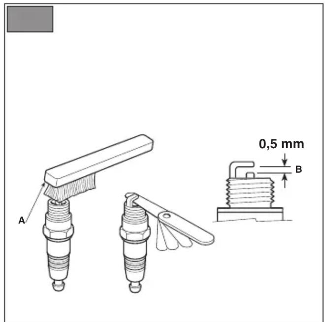
The spark plug (Fig. 31.A) can be accessed by removing the air filter cover (Fig. 37.B).
Periodically remove and clean the spark plug using a metal brush to get rid of any deposits (Fig. 42.A). Check and reset the correct distance between the electrodes (Fig. 42.B). Replace the spark plug and fasten it firmly using the supplied wrench. The spark plug must be replaced with one with the same characteristics whenever the electrodes have burnt or the insulation has worn, and in any case every 100 working hours.
8.6 STARTER CABLE
The starter rope must be replaced by your Dealer or Authorised Service Centre as soon as it shows signs of wear.
8.7 MAINTENANCE OF THE TOOTHED CHAIN
To ensure that the chainsaw works safely and efficiently, it is essential that the cutting means are well-sharpened.
Chain sharpening is necessary when: – the sawdust looks like dust. – cutting becomes more difficult.
– the cut is not straight.
- vibrations increase.
– fuel consumption increases.
⚠️ Kickback may occur if the chain is not sufficiently sharpened
IMPORTANT It is recommended to have a specialised centre sharpen the chain using the right tools to ensure minimum removal of material and even sharpness on all the cutting edges.
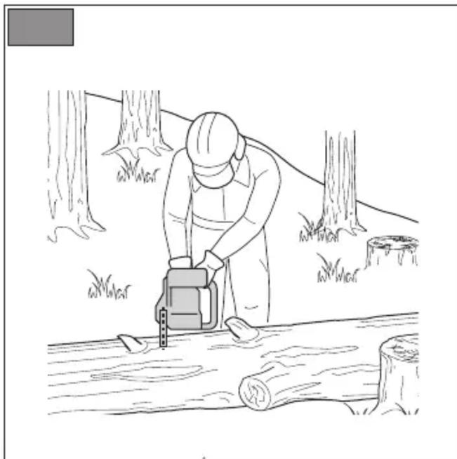
8.7.1 Chain sharpening
If you sharpen the chain yourself, use special round-section files with the right diameter depending on the type of chain (see "Chain Maintenance Table", chap. 14). You need a certain amount of skill and experience to avoid damaging the cutting edges.
Sharpen the chain as follows:
- Stop the machine (par. 6.6).
- Disengage the chain brake (par. 5.7) (.
- Secure the bar with the chain in a vice (Fig. 43.A), so that the chain can run smoothly.
-
Tighten the chain if it is loose (par. 6.1.3).
-
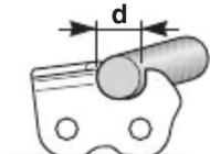
Insert the file in the tooth at a constant angle from the cutting edge (Fig. 43.B). Using a sharpening plate makes using the file easier (Fig. 43.C).
-
Sharpen in a forward motion a few times and repeat this on all the cutting edges facing the same way (right or left).
-
Turn the bar over in the vice and repeat on all the other cutting edges.
-
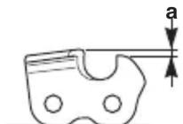
Check that the limiter tooth (Fig. 43.D) complies with the levels indicated in the "Chain Maintenance Table" (chap. 14) and file any projecting parts with a flat file, rounding off the edge.
-
After sharpening, remove all traces of filing and dust and lubricate the chain in an oil bath.
8.7.2 Replacing the toothed chain
Replace the chain when:
- the length of the cutting edges reduces to 5mm or less (Fig. 43.E);
– there is too much play between the links and the rivets.
– the cutting speed is too slow and the repeated sharpening does not improve the cutting speed. The chain is worn.
IMPORTANT After replacing the chain, its tension level must be checked more frequently due to settling of the chain.
8.8 GUIDE BAR MAINTENANCE
NOTE Any work on the guide bar requires specific experience and special tools in order to achieve top workmanship standards; for safety purposes, we recommend you contact your dealer to ensure work is done correctly.
To avoid asymmetrical wear on the bar, make sure it is turned over periodically.
To keep the bar in perfect working order, proceed as follows:
- Grease the bearings on the nose sprocket (if present) with the syringe (not included).
- Clean the bar groove with the scraper (not included) (Fig. 44.A);
- Clean the lubrication holes (Fig. 44.B);
- With a flat file (not included), remove burr from the edges and level off the guides.
8.8.1 Replacing the bar
Replace the bar whenever:
– the groove is not as deep as the height of the drive links (which must never touch the bottom);
– the inside of the guide is worn enough to make the chain lean to one side.
8.9 TUNING MINIMUM SPEED
⚠️ If the cutting means moves when the engine is running idle, contact your dealer or Authorised Service Centre to have the engine adjusted correctly (par. 8.11).
8.10 TUNING THE CARBURETTOR
The carburettor is tuned by the manufacturer to achieve maximum performance in all situations, with a minimum emission of toxic gas in compliance with the regulations in force.
In the event of poor performance, contact your Dealer or Authorised Service Centre for a check of the carburetion and engine.
Carburettor tuning:
T = minimum speed tuning
L = low speed mixture tuning
H = high speed mixture tuning
9. STORING THE MACHINE
IMPORTANT The safety regulations to follow for putting into storage are described in paragraph 2.4. Strictly comply with these instructions to avoid serious risks or hazards.
If you are not going to use the machine for a period of more than 2-3 months, we recommend you do a few things before putting it away. This will make it easier when you want to use the machine again and will also prevent permanent damage to the engine.
Before putting the machine away:
- Unscrew the two clutch housing nuts, remove the housing and remove the chain and bar.
- Empty the oil tank, fill with about 100-120 cc of specific liquid detergent and plug the cap.
- Fit the guard back on without tightening the nuts.
- Start the engine and keep it running until all detergent is used.
- Start the engine and run it idle until it uses up all the fuel that is left in the tank and the carburettor.
- Wait for the engine to cool.
- Remove the spark plug.
- Pour a teaspoon of (new) 2-stroke engine oil into the spark plug slot.
- Pull the starter hand grip several times to deliver oil to the cylinder.
- Replace the spark plug with the piston in the dead end upper position (visible from the spark plug slot when the piston is at maximum stroke).
- Clean the machine thoroughly.
- Check the machine for any damage. If necessary, contact the Authorised Service Centre.
- Store the machine:
- in a dry place
– protected from inclement weather
– with the bar cover guard fitted correctly
– in a place where children cannot get to it - making sure that keys or tools used for maintenance are removed.
Before starting to use the machine again:
- Remove the spark plug.
- Pull the starter hand grip a few times to eliminate excess oil.
- Check the spark plug (par. 8.5).
- Arrange the machine (par. 4.2 chap. 6)
10. HANDLING AND TRANSPORTATION
When handling or transporting the machine, always:
- stop the machine (par. 6.6).
- wait until the chain is stationary.
- remove the spark plug cap (Fig. 31.A).
- mount the bar cover.
– only hold the machine using the hand grips and position the bar in the opposite direction to that used during operation.
When transporting the machine on a vehicle, always:
– position it so that it does not cause a hazard to anyone;
– fasten firmly to the means of transport using ropes or chains to prevent it from tipping over causing damage and fuel leaks.
11. ASSISTANCE AND REPAIRS
This manual provides all the necessary information to run the machine and for correct basic maintenance operations which can be performed by the user. Any regulations and maintenance operations not described herein must be carried out by your Dealer or Authorized Service Centre, which have the necessary knowledge and equipment to ensure that the work is carried out correctly, maintaining the correct degree of safety and the original operating conditions of the machine. Any operations performed in unauthorized centres or by unqualified persons will invalidate the Warranty and all obligations and responsibilities of the Manufacturer.
- Only authorized service centres or dealers can carry out guaranteed repairs and maintenance.
- The authorized service centres or dealers only use genuine spare parts. Genuine spare parts and attachments have been designed specifically for machines.
- Non-genuine spare parts and attachments are not approved. Use of non-genuine spare parts and attachments cause the warranty to be invalidated.
- It is advisable to send your machine once a year to an authorized service centre or dealer for servicing, assistance and safety device inspection.
12. WARRANTY COVERAGE
The warranty covers all material and manufacturing defects. The user must
follow all the instructions provided in the accompanying documentation.
The warranty does not cover damages caused by:
- Failure to become familiar with the documentation accompanying the machine.
- Carelessness.
- Incorrect or prohibited use or assembly.
- Use of non-genuine spare parts.
- Use of attachments not supplied or approved by the manufacturer.
The warranty does not cover:
- Normal wear and tear of consumables, such as cutting means, safety bolts.
- Normal wear and tear.
The purchaser is protected by his or her own national legislation. The purchaser's rights under the national laws or his or her own country are not in any way restricted by this warranty.
- MAINTENANCE TABLE
| Intervention Frequency Paragraph | |||
| First time | An then after | ||
| MACHINE | |||
| Check all fasteners | - Before | each use 7.8 | |
| Safety checks/check controls | - Before | each use 6.2 | |
| Check the chain catcher | - Before | each use 7.7 | |
| Check the machine and bar lubrication holes | - Before | each daily use 8.1 | |
| General cleaning and inspection | - After each use 7.5 | ||
| Cleaning the chain | - After each use 7.6 | ||
| Clutch housing bearing greasing | - 30 hours 7.5 * | ||
| Check the clutch housing | - Once a month 8.3 * | ||
| Check the chain drive sprocket | - Once a month 8.4 * | ||
| Chain maintenance | - | - | 8.7, 14 |
| Bar maintenance | - | - | 8.8 |
| ENGINE | |||
| Checking/topping up fuel level | - Before | each use 7.3. | |
| Topping up the chain oil level | - | Whenever refuelling | 7.4. |
| General cleaning and inspection | - After each use 7.5 | ||
| Cleaning the air filter | 8-10 hours / every season | 8.2 | |
| Cleaning the spark plug | - 10 hours / every season | 8.5 | |
| Replace spark plug | - | 100 hours / every season | 8.5 |
* The operation must be carried out by your Dealer or a Authorised Service Centre
14. CHAIN MAINTENANCE TABLE
| Chain pitch | Limiter tooth level (a) File diameter (d) | ||||
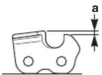 | 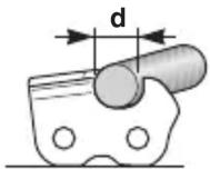 | ||||
| inches mm | inches mm inches mm | ||||
| 3/8 Mini | 9.32 | 0.018 0.45 5/32 4.0 | |||
| 0.325 | 8.25 | 0.026 0.65 3/16 4.8 | |||
| 3/8 | 9.32 | 0.026 0.65 13/64 5.2 | |||
| 0.404 | 10.26 | 0.031 0.80 7/32 5.6 | |||
This table gives the sharpening data for different types of chains, but this does not mean you can use chains other than
those approved and listed in the "Correct bar and chain combination table".
15. PROBLEM IDENTIFICATION
If problems persist after having performed the above operations, contact your dealer or an Authorised Service Centre.
| PROBLEM PROBABLE CAUSE REMEDY | ||
| 1. The engine will not start or will not keep running | Incorrect starting procedure. Follow | the instructions (par. 6.3) |
| Dirty spark plug or incorrect distance between the electrodes | Check the spark plug (par. 8.5). | |
| Air filter clogged Clean and/or replace | ce the filter (par. 8.2). | |
| Anti-freeze device assembled incorrectly | Check the assembly position (par. 6.1.4) | |
| Carburetion problems Contact the Authorised Service Centre or dealer.. | ||
| 2. The engine starts but lacks power. | Air filter clogged Clean and/or replace | ce the filter (par. 8.2). |
| Carburetion problems Contact the Authorised Service Centre or dealer. | ||
| 3. The engine runs irregularly and lacks power when revved | Dirty spark plug or incorrect distance between the electrodes | Check the spark plug (par. 8.5). |
| Bar and chain problems Check that | the chain runs freely and the bar guides are not deformed. | |
| Carburetion problems Contact the Authorised Service Centre or dealer. | ||
| 4. The engine makes too much smoke | Incorrect composition of the fuel mixture | Prepare the fuel mixture according to the instructions (par. 7.2) |
| Carburetion problems Contact the Authorised Service Centre or dealer. | ||
| 5. If the engine floods | The starter grip has been driven repeatedly with the choke engaged. | Remove the spark plug (par. 8.5) and gently pull the starter rope hand grip (Fig. 11.D) to eliminate any excess fuel; then dry the spark plug electrodes and remount it on the engine. |
| 6. No oil is released | Poor quality oil When the engine is | cold, emptythe tank, clean it and the pipes withliquid detergent and change the oil. |
| Lubrication holes are clogged Clean them (chap. 8.1) | ||
| 7. The chain moveswhen the engineis running idle | Incorrect adjustmentof fuelling | Contact the AuthorisedService Centre or dealer. |
| 8. The machine startsto vibrate abnormally | Damaged or loose parts. Stop the machine and disconnectthe spark plug cable (Fig. 31.A).Inspect for damage.Check and tighten any loose parts.Have all checks, repair workand replacements carriedout by an Authorised ServiceCentre or dealer only. | |
| 9. The machine hasstruck a foreign body. | Damaged or loose parts. Stop the machine and disconnectthe spark plug cable (Fig. 31.A).Inspect for damage.Check and tighten any loose parts.Have all checks, repair workand replacements carriedout by an Authorised ServiceCentre or dealer only. | |
16. ACCESSORIES
The "Correct bar and chain combination table" contains a list of all possible combinations between bar and chain, indicating those which may be used on each machine, marked with the symbol "✓".
The same table also provides the specification data for all chains and bars approved for use on each machine.
Only use the replacement bars and chains listed in the table. The use of unapproved combinations may be hazardous and cause serious injuries to operators and damage the machine.
In consideration that the selection, application and use of the bar and chain are actions made solely by the user, at his own discretion, the latter assumes responsibility for damages of any kind arising from such actions. When in doubt or if lacking knowledge of the specifics
of each bar or chain, contact your dealer or Authorised Service Centre.
ÍNDICE
1.1 KUIDAS KASUTUSJUHENDIT LUGEDA
8.8 SAEPLAADI HOOLDUS
- SÄÄNNÖLLINEN HUOLTO....13
7.2 POLTTOAINESEOKSEN VALMISTUS
10. MANUTENTION ET TRANSPORT
8.3 SANKABOS VARPELIS
- PLĀNOTĀ TEHNISKĀ APKOPE 13
7. PLĀNOTĀ TEHNISKĀ APKOPE
7.1 VISPĀRĒJA INFORMĀCIJA
7.7 KĒDES BREMZES TAPA
2.5 BESCHERMING VAN DE OMGEVING
2.4 VEDLIKEHOLD, LAGRING
3. BLI KJENT MED MASKINEN
3.1 BESKRIVELSE AV MASKINEN OG BEREGNET BRUK
Maskinen er et skogsbruksredskap, nærmere bestemt en bensindrevet motorkjedesag for arbeid i skogen.
7. ORDINÆRT VEDLIKEHOLD
7.1 GENERELT
7.3 ETTERFYLLING AV DRIVSTOFF
8. EKSTRAORDINÆRT VEDLIKEHOLD
8.1 SM∅REHULL PÅ MASKINEN OG SVERDET
8.7 VEDLIKEHOLD AV SAGKJEDET
8.8 VEDLIKEHOLD AV SVERDET
13. VEDLIKEHOLDSTABELL
14. VEDLIKEHOLDSTABELL FOR KJEDET
| Spor til kjedet | Nivået til begrenserskjærtannen (a) | Filens diameter (d) | |||
 |  | ||||
| tommer | mm | tommer | mm | tommer | mm |
| 3/8 Mini | 9,32 | 0,018 | 0,45 | 5/32 | 4,0 |
| 0,325 | 8,25 | 0,026 | 0,65 | 3/16 4,8 | |
| 3/8 | 9,32 | 0,026 | 0,65 | 13/64 | 5,2 |
| 0,404 | 10,26 | 0,031 | 0,80 | 7/32 5,6 | |
6.1 CZYNNOŚCI WSTĘPNE
3. Len pre model SP 526:
Stlačte dekompresný ventil (obr. 13.E).
POZNÁMKA Okamžite po
6.4 PRACOVNÁ ČINNOSŤ
- UPOTREBA MASINE....8
6.1 Pripremne radnje....8
6.2 Sigurnosne kontrole 9
6.3 Pokretanje 10
6.4 Rad 11
6.5 Saveti za upotrebu....13
6.6 Zaustavljanje 13
6.7 Nakon upotrebe....13
- REDOVNO ODRŽAVANJE 13
7.1 Uopšteno.... 13
7.2 Priprema mešavine 14
7.3 Sipanje goriva 14
7.4 Sipanje ulja u rezervoar ulja za lanac ..... 14
7.5 Čišćenje mašine i motora 15
7.6 Cišćenje lanca.... 15
7.7 Osovina za blokiranje lanca.... 15
7.8 Matice i šrafovi za fiksiranje 15
- VANREDNO ODRŽAVANJE 15
8.1 Uljni otvori na mašini i maču 15
8.2 Čišćenje filtera za vazduh.... 15
8.3 Zvono spojke.... 15
8.4 Pogonski zupčanik lanca.... 16
8.5 Kontrola svećice 16
8.6 Sajla za paljenje 16
8.7 Održavanje ozubljenog lanca 16
8.8 Održavanje mača 16
8.9 Regulacija minimalne brzine 17
8.10 Regulacija karburatora 17
-
SKLADIŠTENJE 17
-
POMERANJE I TRANSPORT 17
- ASISTENCIJA I POPRAVKE 18
- POKRICE GARANCIJE 18
- TABELA S INTERVENCIJAMA ODRŽAVANJA.....18
- TABELA S INTERVENCIJAMA ZA ODRŽAVANJE LANCA....19
- PREPOZNAVANJE PROBLEMA....19
- DODATNA OPREMA 20
1. UOPŠTENO
1.1 KAKO SE SLUŽITI PRIRUČNIKOM
U tekstu priručnika neki paragrafi koji sadrže informacije od posebnog značaja, u pogledu sigurnosti ili rada, istaknuti su na drugačiji način, prema sledećem kriterijumu:
NAPOMENA ili VAŽNO navodi detalje ili druge elemente u vezi sa već prethodno naznačenim, radi izbegavanja oštećenja mašine ili uzrokovanja štete.
INNEHÅLLSFÖRTECKNING
5.7 HANDTAG FÖR MANUELL START
8.1 APPARATENS OCH SVÄRDETS SMÖRJHÅL
D. Lgs. 262/2002, ANNEX V (Italy)
Senior VP Product Technical Division
Maurizio Tursini

D. Lgs. 262/2002, ANNEX V (Italy)
Senior VP Product Technical Division
Maurizio Tursini

| FR (Traduction de la notice originale)Déclaration CE de Conformité(Directive Machines 2006/42/CE, Annexe II, partie A)1. La Société2. Déclaré sous sa propre responsabilité que la machine : Sècle à châne pour travaux forestiers abtagatértonconnage/branchange d'arbres a) Type / Module de Base b) Series / Année de construction c) Série d) Moteur; moteur essence 3. Est conforme aux prescriptions des directives e) Organisme de certification f) Examen De type K、Renvoi aux Normes harmonisées g Niveau de puissance sonore mesuré h) Niveau de puissance sonore garanti j) Puissance nette installée n) Personnse habitilitée à établir le Dossier Technique o) Lieu et Date | EN (Translation of the original instruction)EC Declaration of Conformity (Machine Directive 2006/42/EC, Annex II, part A)1. The Company2. Herby declares under its own responsibility that the machine: Chainsaw for forest service felling, bucking, delimbing trees a) Type / Base Model b) Month / Year of manufacture c) Model / Model d) Engine: petrol 3. Conforms to directive specifications: e) Certifying body f) EC examination of Type 4. Reference to harmonised Standards g) Sound power level measured h) Sound power level guaranteed j) Net power installed n) Person authorised to create the Technical Folder; o) Place and Date | DE (Übersetzung der Originalbetriebsanleitung )EG-Konfornitätserklierung (Maschinenrichtlinie 2006/42/EG, Anhang II, Teil A)1. Die Gesellschaft 2. Enklart auf eigene Verantwortung, dass die Maschine: Kettensäge für die Forstarbeit fällen/schneiden/entasten von Bäumen i) Typ / Basellmodell b) Monat / Saurar c) Seriennummer d) Motor: Verbrennungsmotor 3. Den Anforderungen der folgenden Richtlinien entspricht; e) Zertifizierungsstelle f) EG-Baumansterprüfung 4. Bezugnahme auf die harmonisierten Normen g) Handlertter Schallleistungspegel h) Garantierter Schallleistungspegel j) Installierte Nettoleistung n) Zur Verflussung der technischen Unterlagen befragte Person; o) Ort und Datum | NO (Oversettelse av original bruskanvisning)EF- Samsverserklering (Maskinärektiv 2006/42/EF, Vedlegg II, del A)1. Firmaat 2. Erklaer på eget ansvar at maskinen: Kjedesag for vanlig skogbruk Nedfelling/kutt/vkisting av trær a) Type / Model b) Männel / Tilverkningsár c) Seriennummer d) Motor: forbrenningsmotor 3. Oppylier kravene i Direktivene: e) Sertifiseringorgan f) EF-typeprevning 4. Henvisning til harmoniserte standarder g) Målt dyteffektivná h) Garantiert dyteffektivná j) Installiert nettoeffekt n) Person som har fullmakt til å ufterdige teknisk dokumentasjon: o) Sted og dato | SV (Oversättning av bruskanvisning i original)EG-försåkran om översenstämmelse (Maskinärektiv 2006/42/EG, bilaga II, de la)1. Företaget 2. Förstärer på eget ansvar at maskinen: Kedjesag för skogsarbete Fällning/kapning/grenkilppning av trä d) Typ / Basmodel b) Männel / Tilverkningsár c) Männel / Konstruktionsár d) Motor: förbränningsmotor 3. Overensänmster med foreskrifterna i direktivet e) Intysgorgan, Anmålt organ f) EG typogdkännande 4. Referens till harmoniserade standarder g) Uppmitt judeffektivná h) Garantiert judeffektivná j) Installerad nettoeffekt n) Auktoriserad person för uprättandet av den tekniska dokumentationen: o) Ort och datum | DA (Oversættelse af den originale brugsanvisning)EF-overensstemmlesserkerling (Maskinärektiv 2006/42/EF, bilaga II, del A)1. Firmaat 2. Erklaer på eget ansvar at maskinen: Kædesar til skovarbejde Faldining af træer/udskarering af stykker/opskæring af grene a) Type / Model b) Männel / Konstruktionsár c) Seriennummer d) Motor: förbrändingsmotor 3. Er I overensässelme med specifikationerne ifelge direktiverne: e) Certifieringsorgan f) EF-typeprevning 4. Henvisning til harmoniserede standarder g) Målt dyteffektivná u) Garantiert lydeffektivná j) Installerad nettoeffekt n) Auktoriserad person för uprättandet av den tekniska dokumentationen: o) Ort och datum | |||||||||||||||||||||||||||||||||||||||||||||||||||||||||||||||||||||||||||||||||||||||||||||||||
| NL (Vertaling van de conspronkelijke gebruiksaanwijzing)EG-verklarying van overengamtemming (Richtlichigen Machines 2006/42/CE, Bijlage II, deel A)1. Het bedrif & 2. Verkaart onder zijn eigen verantwoordkeijheid dat de machine: Kettingzag voor boswerken vellen/snijden/snoelen van bomen a) Type / Basismodel b) Maasnd / Bouwayjar q) Serringer d) Motor: accu 3. Voldoet aan de specificities van de richtlijnen: e) Certificatie-institut f) EG-onderzoek van het Type 4. Verwijzing naar de Geharmoniseerde normen g) Gemeten niveau van geluidsvermogen h) Gegaranderd niveau van geluidsvermögen j) Netto geinstalleider vermogen g) Bevoegd person voor het opstellen van het Technisch Dossier o) Plaat en Design | ES (Traducción del Manual Original)Declaración de Conformidad CE (Directiva Maquinas 2006/42/CE, Anexo II, parte A)1. La Empresa 2. Declare baal su propia responsabilidad que la máquina: Motosierra de cadena para trabajos forestales tala/-seccionamento/poda de árboles a) Tipo / Modelo Base b) Mes / Año de fabrication c) Matricula d) Motor: motor de explosión 3. Cumple con las especificaciones de las directives: e) Ente certificador f) Examen CE del Tipo 4. Referencia a las Normas armonizadas g) Nivel de potencia sonora medido h) Nivel de potencia sonora garantizado j) Potencia neta instalada n) Persona autorizada a realizar el Manual Técnico o) Lugar y Fecha | PT (Traducción do manual original)Declaração CE de Conformidade (Diretiva de Maquinas 2006/42/CE, Anexo II, fl) 1. A Empresa 2. Declara se Motosserra para trabalhos forestaals abate/seconamento/desramação b a própria responsabilidade que a máquina: a) Tipo / Modelo Base b) Mês / Año de fabrico c) Matricula d) Motor: motor a explosão 3. E. conformá as especificações das diretivas: e) Orgaco certificador f) Exame CE do Tipo 4. Referência às Normas harmonizadas g) Nivel medido de potência sonora h) Nivel garantido de potência sonora j) Potência líquida instalada n) Pessoa autorizada a elaborar o Caderno Técnico o) Local e Data | FI (Aikuperäisten ohjeden kälännös)EY-AATIMUSTENMIKUAISUUSVAKUUTUS (Konredirektivi 2006/42/EY, Liite II, osa A) 1. Yritys 2. Vakuuttaa ornalla vastuillaan, että kone: Mootitorśaha metsäholtlohom Puiden kaataminen/pilkomionen/karsinta a) Typpi / Perusmallii b) Kuukausi / Valmistusvuosi c) Sarjansmero d) Moottori / rajähdysmoottori 3. On yhdenmukainen sourauvien direktiivien asettamien vaatimuten kanssa: e) Sertifinóthyisy f) EY-tyypitpartakust 4. Viittaus harmonisoltiuhin standardeling g) Malttu äneihetohaso h) Taattu äneihetotaso j) Asennettu nettoelho n) Tekplisten asiakrijojen laatimiseen valtuutettu henkiło: o) Paikka ja päivämärär | CS (Překlad původního návodu k používání)ES – Prohlášení o shodě (Smérnicce o Strojních zařizhenich 2006/42/ES, Příloha II, část A) 1. Společnost 2. Prohlášuje na vlastní odpovědnost, že stroj: Rétžová motorová pila pro lesnické práce Kácení/rozežavání/odvětvování stromů a) Typ / Základní model b) Mísic / Roh výroby c) Výrobi číslo d) Motor: spolavaci motor 3. Je ve shodě s najzenimi směníc: e) Certifikacjana Organ f) ES zkuoka stru Typu 4. Odkazy na Harmonizované normy g) Naměření úroveň akustického vykonu h) Zanucéná úroveň akustického vykonu j) Cisty instalovany výkon o) Osoba autorizovaná pro vytrofení Technického spisu: o) Misto a Datum | PL (Tumaczenie instrukcji oryginalnej)Deklaracja zgodności WE (Dyrektya maszynowa 2006/42/WE, Załącznik II, częś Č) 1. Spółka 2. Owiwiedca za naaligned odpowiedziánność, že maszyna: Pilarka lańcuchaowa do prac lesných Ścinanie, obalandie/przerzynamie/okrzeszywanie drzew a) Typ / Model podstawowy b) Miesiac / Roh produkcji c) Numer serjyny d) Silnik: silnik o zaptonie iskryowm 3. Spelnia podstawowe wymogi nastepupychany Dryektyw: e) Jednostka certyfikująca f) Badanie typy uyle 4. Odnieslenie do Norm zharmonizowanych g) Zmierzony poziom mocy akustycznej h) Gwarantowny poziom mocy akustycznej j) Moc zainstalwána netto n) Osoba upošawnziona do zredagowania Dokumentacije technicznej: o) Mięscołwość i data | |||||||||||||||||||||||||||||||||||||||||||||||||||||||||||||||||||||||||||||||||||||||||||||||||
| EL (Metáfoppəntou προματότου των οδηγών χρετική)EK-Δλωσηση συμμάρφωστις (Öbnyia Myxωνών CE, Çe, Ποράτθμα II, μροσ Α) 1.1 El Parta 2. Δλωπώνι υπεύθυν ατή μη μανονί: Λλυστριστονο για δασκές εργσίες Καττράργκηταποτερική ποκή κλαδιών έντρων r) A) Barmko Montovilio b) Mytivos / Etos κατοκευται c) Αρήμος μπτρου δ) Κινητρος: κνητήρος εσμπερικής ανόμελης 3. Σαρροφώνεται νε της προδιανφρας της οδηγικό: o) Οργανισκός πιστοποίησης f) Εξτσησί ΡΕ του Τομον Φ) Αντήσε τους Κονονομούς ενσμενσίνης g) Εξτόθμη μετρησης ακοστυκής ισχούς h) Εξτόθμη εγναμησενς ακοστυκής ισχούς j) Καθερή εγναστοπείνη χριας η Εξονοσδομητον στισμο για την κατάρτσιη του Τεχνικού Φιλαλδίου: o) Τοτός και Χρόνος | TR (Originai Talmaitların Tercümesi) AT Ugyunkliuk Beyani (2006/42/CE Makine Direktifl, Ek It, būlüm A) 1. Sirket 2. Sefti sorumluluğu altında ασμάρδaki makinenin: Orman iglet için zincinrii testere Ασαζιλη κείνη δαβίμηmseldallarmn budmannasi a) Tip / Topi and tel d) Üretimin Ay y /ül c) Sicil numarasi d) Motor: patlamali motor 3. Ασμάδικά direktelfrir ézilikliikerie uygun ofråden numelid#: e) Sertifikalandiran kurum f) ... Tipi CE incelemsi 4. Harmonize standardità atf d) Órliche gesus des sévinyei h) Garantil edilen ses güß seviyesi j) Kurulu net güß n) Teknik Dosyasyi olusturmaya yetkili kijš: o) Yer ve Path | MK (Prüvedő ha originálne ypitástia)Декларация за угласненост со EU (Директива за машини 2006/42/CE, Annex II, del A) 1. Κοληναίτα 2. ισαλήσινα σο целосна лична одговорност дека следната машина: Моторна липа со синирур за работа во шума Соборувающая на котельные на два a) Typi I основи модел b) Mesecl / Година на производство e itiknta) Motors: cơ соруговуана 3. Усепловаю соплификациите според директивте: d) тело за сертифициација) τρε σε τημοτή τρε σε τημοτή τρε σε τημοτή τρε σε τημοτή τρε σε τημοτή τρε σε τημοτή τρε σε τημοτή τρε σε τημοτή τρε σε τημοτή τρε σε τημοτήτρε σε τημοτή τρε σε τημοτή τρε σε τημοτή τρε σε τημοτή τρε σε τημοτή τρε σε τημοτή τρε σε τημοτή τρε σε τημοτή τρε σε τημοτή τΡε σε τημοτή τρε σε τημοτή τρε σε τημοτή τρε σε τημοτή τρε σε τημοτή τρε σε τημοτή τρε σε τημοτή τρε σε τημοτή τρε σε τημοτή τρα εκτήσικό στετησίκό στετησίκό στετησίκό στετησίκό στετησίκό στετησίκό στετησίκό στετησίκό στετησίκό στετησίκό στετησίκό στετησίπος f) Ι Ισπλε στετησίκό στετησίκό στετησίκό στετησίκό στετησίκό στετησίκό στετησίκό στετησίκό στετησίκό στετησίκό στετησίκό |
| SL (Prevod odzivnih navodi)ES Izjava o skladnosti(Direktiva 2006/42/ES), prillogi II, del A)1. Pod starno odgovorostjo izjavla, da je stroj:Verlžna žaga za gozdna dela,Podranje/szrevanje/ostranejevanje vej2. Podnabrje/szrevanje/ostranejevanje vej3. MeseC, Leto izdelavec) Serijkaštevička d) Motor: motor z notranjim izgovorevanem3. Skladjen je z določili/direktiv :e) Ustanova, ki izda potrilo f) ES pregođ tipa4. Skliczevalije na usklajene predpise5. Izmerjen nivo zvočne moći6. Zagetovjen nivo zvočne moći j) Neto instaltrana moći n) Osoba, podlošćena za sestavo tehnične knjičice o) Kraj in datum | BS (Přejevod originanih uputa)EZ Izjava o sukladnosti(Direktiva o mašinama 2006/42/EZ, Prilog II, deo uzuba)1. Firma2. Daje izjavu pod vlaststom odgovornošću da je mašina: Lančana močima pila za šumarstvo Obaranje i sjęca drveća/rezanje grana3) Tip / Osnovni model4) Mjesć / Godina proizvodnje5) Serijski broj6) Motor: motor s unutrašnjim izgaranjem8) Izmerjen nivo zvučne snage9) Garantovani nivo zvučne snage j) Neto instaltsana snaga n) Osoba ovišćena za izradu tehničke brošure: o) Mjesto i data | SK (Preklad původného nivoduva na použitie)ES vyhlásenie o zhode(Siemnica o Strojnych zariadenlach 2006/42/ES, Prillogi II, daža A)1. Spoločnost2. Vhylasuje na vlastnú zodpovednosť, že stroj:Retžavává motorová pila pre lesnické práce, Stinanie/mrozrezvanie/odvetovanje stomov a) Typ / Základý numde b) Mesiac / Rok vryoby c) Výrobná číslo d) Motor: spaflovaci motor3. Je v zhode s nariadeníami smernic: e) Certifikacý orgán f) Skulka typu E) Oskaz na Harmonizované normy g) Nameraná úroveň akustického výkonu h) Zaručená úroveň akustického výkonu j) Čistý instalovaný výkon n) Osoba autorizovaná na vytvorenie Technického splat: o) Miesto a Dátimo |
| RO (Traducerea manualului fabricantului)CE -Declaratie de Conformitate (Direktiva Mašini 2006/42/CE, Anexa II, partea A)1. Societatea2. Declará je propria răspundere că mašina: erlastrăti/ lent pentru lucrări forestiere Doborare/sectionare/tälerea ramurilor de copaci a) Tip / Model de bazá b) Luna di fabricatie c) Număr de serie d) Motor: motor cu combustie 3. Este in conformitate cu specifica( tile direktorior) Organism de certificare f) Examinarne CE de Tip 4. Referintja la Standardele armonizate g) Nivel da putere sonoră măsaurat h) Nivel de putere sonoră garantat j) Putere neta instalată n) Persona autorizata să întocmească Dosarul Tehnic o) Loculi și Data | LT (Originali/ instrukciju/ uvertirmas)EB attitiklés deklaracija(Mašinu direktyva 2006/42/CE, Priedas II, dalis A)1. Bendrové2. Prisilma atsakomybe, kad [rejinginy: Gondrininis půklas milko darbans/Medžtju kirtimas/pjuajstymas/genejimas a) Tipas / Bazinis Models b) Ménuo / Pagunimo metal c) Serijos numeris d) Variklis: viađas degimo variklis 3. Alttnka direktyvoše pateiktas specifikacijas: e) Sertifikavimo istága f) CE tipo lyrīmas 4. Nuoroda i suderintas Normas g) Išmatuotas garso galios lygls i) Užikrinamasi garso galios lygls j) Instaliuota naudingoji galia n) Autorizuotas asmuo sudariti Techniņng Dokumentaciją: o) Vieta ir Data | LV (Instrukciju tulkojums no originalálvodas)EK altitibšitas deklaracija (Direktiva 2006/42/EK par mašinám, pielikums II, daja A)1. Uzpěnimus2. Izmenotimes par to plinu altibšību, pazino, ka mašina: Grandninis půklas milko darbams Koku glāsanazaglēsana/atzarosana a) Tips / Bagné modells b) Ménesis / Rožašanas gads c) Sérijas numurs d) Motors: lekšdědzes motors 3. Albitšt šádu direktvù prasibám: e) Sertifikacijas iestáde f) CE tipvekta párbaude 4. Atsauce uz harmonizitěmi standartiem g) Izmeritlais skapas intensitātes limeris h) Garantētais skapas intensitātes limeris j) Uzstādīta neto juda n) Pilvinoratals darbiněks, kas sagatvoja tehnisko dokumentādju: o) Vieta i den units |
| SR (Prevod originalih upuststva)EC deklaracija o usaglasnenosti Direktiva o mašinama 2006/42/EC, Prilog II, deo A)1. Predužeće2. Daje izjavu pod vlaststom odgovornošću da je mašina: erlatrav na motorna testera za šumarstvo Obaranje i seča drveća/rezanje grana a) Tip / Osnovni model b) MeseC / Godina proizvodnje c) Serijski broj d) Motor: motor s unutrašnjim sagorevanjem 3. u skladu s osnovnim zahtvima direktiva: e) Sertifikaciono telo f) EC ispitivanje tipa4. Pozvirje na ukladneje norme g) Izmereni nivo zvučne snage h) Garantovani nivo zvučne snage i) Širina košenja ..... Neto installasana snaga n) Osoba ovišćena za sastavljanje tehničke brošure o) Mesto i datum | BG (Prevod na originalnalite инструкции)EO declaračnja za ́cotriebствие (Direktiva Mašini 2006/42/EO, Prilokningii II, что: ́Дружеството 2. На собствие отговорност декларира, че машистата: Моторен верижа трион за горки работи,Сечнарязване на трупи/окастряне клоните на дървета a) Вид / Бизисен модел b) Meseć/ бодина на производство c) Сермен номер r) Motor: мотор с вътрешко горене 3. Е в ́cotriebствие със спецификата на дрективаците: d) Certifikacijraçard organ e) EO изследане на вида 4. Базирano на звадронизраните норми ж) Ниво на измерена акустична мощност i) Гаританриво ниво на акустична мощност j) Нетна инсталирана мощност r) Лице, упільномощено да сътстави Техническата Документация: o) Mesto i data | ET (Algupirasase kasutusjuhenditõlige)EÜ vastvasudeklaratiscon (Masinadirektivi 2006/42/EU, Lisa II, osa A)1. Firma2. Kinnitab omal vastutsel, et masin: Kettsaag metsatõödek 4. Puude langetamine/järkamine/faasimine a) Tüüp / Põhimud b) Kuu sega / Tootmisaaasta o) Matrikker f) Mood: Slepõlemismootor 3. Vastab direktviđe nõutele: e) Kinnitav asutus f) EU tüüghindamine 4. Vide inklustatud standarditele g) Möddetud helvolömsuse tase h) Garanteeurtud helvolömsuse tase j) Installeertud netovömsuis n) Tehnilise Lehe autorisertud koostaja: o) Koht ja Kuipäev |
EN • The content and images in this User Manual were produced expressly for STIGA S.p.A. and are protected by copyright – any unauthorised reproduction or modification to the document, either partially or in full, is prohibited.
Type:


- USO DELLA MACCHINA
- PRACOVNÍ ČINNOST
- TYPESKILT PÅ PRODUKTET
- SM∅REHULLER I MASKINEN OG I SVÆRDET
- GENERAL INFORMATION
- HOW TO READ THE MANUAL
- REFERENCES
- Figures
- Titles
- SAFETY REGULATIONS
- TRAINING
- PREPARATION
- Personal Protective Equipment (PPE)
- Internal combustion engines: fuel
- DURING OPERATION
- Work Area
- Behaviour
- Use limitations
- Maintenance
- Storage
- ENVIRONMENTAL PROTECTION
- GETTING TO KNOW THE MACHINE
- DESCRIPTION OF THE MACHINE AND PLANNED USE
- Intended use
- Improper use
- User types
- SAFETY SIGNS
- BEWARE OF KICKBACK!
- PRODUCT IDENTIFICATION LABEL
- MAIN COMPONENTS
- ASSEMBLY
- ASSEMBLY COMPONENTS
- Unpacking
- ASSEMBLY OF THE GUIDE BAR AND TOOTHED CHAIN
- Checking the chain tension
- CONTROLS
- ENGINE START/STOP SWITCH
- CHOKE LEVER
- PRIMER CONTROL BUTTON
- PRESSURE RELIEF VALVE CONTROL (FOR MODEL SP 526 ONLY)
- THROTTLE TRIGGER LEVER
- INTERLOCK LEVER
- HANDLE FOR MANUAL START
- CHAIN BRAKE
- USING THE MACHINE
- PREPARATION
- Refuelling
- Filling with chain lubrication oil
- Checking the chain tension
- Always wear heavy duty gloves.
- ⚠️ Never work with the chain loose as it can be hazardous if the chain slips out of the bar guides.
- Preparing the machine before starting work
- - Anti-freeze device
- 3.a on models SP386, SP 426:
- 3.b on models SP466, SP 526:
- SAFETY CHECKS
- General check
- Machine operating test
- STARTUP
- IMPORTANT
- Startup from cold
- Warm start
- OPERATION
- Stop the machine immediately e chain stops during sawing.
- Checks to be conducted whilst working
- 6.4.1.a Checking the chain tension
- 6.4.1.b Checking the oil delivery
- Make sure the bar and the chain are place when you check the oil delivery.
- Work techniques
- 6.4.2.a Delimbing a tree
- ⚠️ Make sure there is nothing or anybody in the area where the branches will fall.
- 6.4.2.b Felling a tree
- - Performing a face notch
- - Felling back cut
- 6.4.2.c Limbing tree branches
- 6.4.2.d Bucking the trunk
- - Trunk resting on one end only
- - Trunk resting on both ends
- - Sloping trunk
- STOP
- AFTER OPERATION
- ROUTINE MAINTENANCE
- GENERAL INFORMATION
- Before conducting any
- PREPARING THE FUEL MIXTURE
- Petrol characteristics
- Oil characteristics
- Preparation and storage of the fuel mixture
- REFUELLING
- TOPPING UP THE CHAIN OIL TANK
- CLEANING THE MACHINE AND THE ENGINE
- CLEANING THE CHAIN
- CHAIN CATCHER
- NUTS AND BOLTS
- EXTRAORDINARY MAINTENANCE
- MACHINE AND BAR LUBRICATION HOLES
- CLEANING THE AIR FILTER
- CLUTCH HOUSING
- CHAIN DRIVE SPROCKET
- CHECKING THE SPARK PLUG
- STARTER CABLE
- MAINTENANCE OF THE TOOTHED CHAIN
- ⚠️ Kickback may occur if the chain is not sufficiently sharpened
- Chain sharpening
- Replacing the toothed chain
- GUIDE BAR MAINTENANCE
- Replacing the bar
- TUNING MINIMUM SPEED
- TUNING THE CARBURETTOR
- STORING THE MACHINE
- HANDLING AND TRANSPORTATION
- ASSISTANCE AND REPAIRS
- WARRANTY COVERAGE
- CHAIN MAINTENANCE TABLE
- PROBLEM IDENTIFICATION
- ACCESSORIES
- ÍNDICE
- KUIDAS KASUTUSJUHENDIT LUGEDA
- SAEPLAADI HOOLDUS
- POLTTOAINESEOKSEN VALMISTUS
- MANUTENTION ET TRANSPORT
- SANKABOS VARPELIS
- PLĀNOTĀ TEHNISKĀ APKOPE
- VISPĀRĒJA INFORMĀCIJA
- KĒDES BREMZES TAPA
- BESCHERMING VAN DE OMGEVING
- VEDLIKEHOLD, LAGRING
- BLI KJENT MED MASKINEN
- BESKRIVELSE AV MASKINEN OG BEREGNET BRUK
- ORDINÆRT VEDLIKEHOLD
- GENERELT
- ETTERFYLLING AV DRIVSTOFF
- EKSTRAORDINÆRT VEDLIKEHOLD
- SM∅REHULL PÅ MASKINEN OG SVERDET
- VEDLIKEHOLD AV SAGKJEDET
- VEDLIKEHOLD AV SVERDET
- VEDLIKEHOLDSTABELL
- VEDLIKEHOLDSTABELL FOR KJEDET
- CZYNNOŚCI WSTĘPNE
- Len pre model SP 526:
- PRACOVNÁ ČINNOSŤ
- UOPŠTENO
- KAKO SE SLUŽITI PRIRUČNIKOM
- INNEHÅLLSFÖRTECKNING
- HANDTAG FÖR MANUELL START
- APPARATENS OCH SVÄRDETS SMÖRJHÅL
Brand : STIGA
Model : SP 426
Category : Saw