
BioMaster 350 - Water filter OASE - Free user manual and instructions
Find the device manual for free BioMaster 350 OASE in PDF.
| Product Type | External aquarium water filter |
| Brand | Oase |
| Model | BioMaster 350 |
| Category | Water filter |
| Dimensions (L × W × H) | 240 × 240 × 425 mm |
| Weight | 4.5 kg |
| Rated voltage | 230 V AC |
| Frequency | 50 Hz |
| Power consumption (filtration) | 18 W |
| Power consumption (optional heating) | 200 W |
| Protection rating | IPX4 |
| Maximum flow rate | 1100 L/h |
| Maximum delivery head | 1.4 m |
| Maximum water column | 1.8 m |
| Filter volume | 5.6 L |
| Pre-filter volume | 0.5 L |
| Recommended for aquarium | Up to 350 L |
| Hose connection (diameter) | 17 mm |
| Power cable length | 1.5 m |
| Filter media included | Filter foam (10-30 ppi), Hel-X bioelements |
| Maintenance and cleaning | Clean pre-filter and filter media with clear water; use OASE PumpClean for limescale |
| Safety | Dry-run protection; disconnect before any maintenance; do not use if cable or housing is damaged |
| Spare parts and repairability | Wear parts: filter media, function unit, suction cups. Spare parts at www.oase-livingwater.com |
Frequently Asked Questions - BioMaster 350 OASE
User questions about BioMaster 350 OASE
0 question about this device. Answer the ones you know or ask your own.
Ask a new question about this device
Download the instructions for your Water filter in PDF format for free! Find your manual BioMaster 350 - OASE and take your electronic device back in hand. On this page are published all the documents necessary for the use of your device. BioMaster 350 by OASE.
USER MANUAL BioMaster 350 OASE
BioMaster 250/350/600/850
BioMaster Thermo 250/350/600/850
EN Operating instructions
FR Notice d'emploi
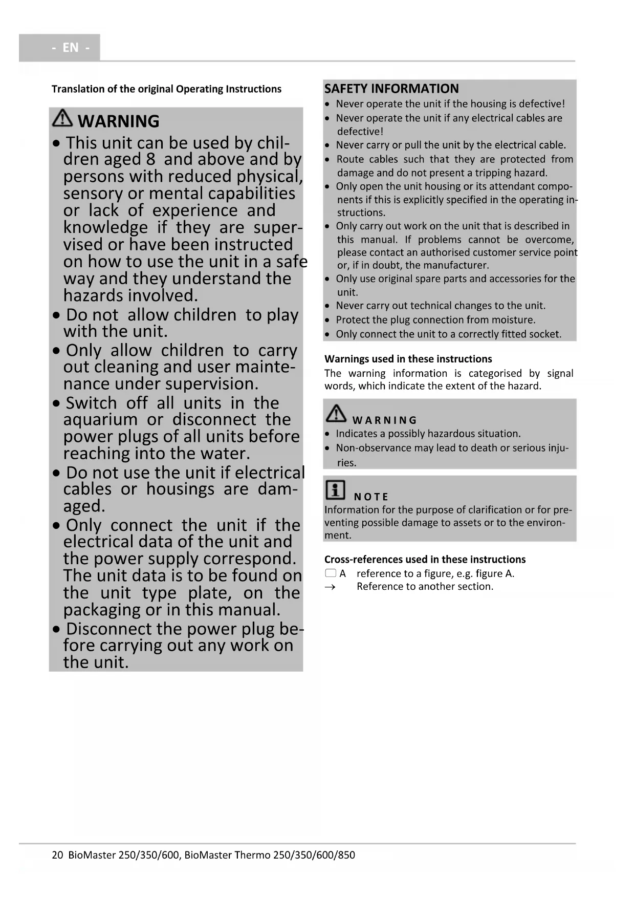
Translation of the original Operating Instructions
WARNING
- This unit can be used by children aged 8 and above and by persons with reduced physical, sensory or mental capabilities or lack of experience and knowledge if they are supervised or have been instructed on how to use the unit in a safe way and they understand the hazards involved.
- Do not allow children to play with the unit.
- Only allow children to carry out cleaning and user maintenance under supervision.
- Switch off all units in the aquarium or disconnect the power plugs of all units before reaching into the water.
- Do not use the unit if electrical cables or housings are damaged.
- Only connect the unit if the electrical data of the unit and the power supply correspond. The unit data is to be found on the unit type plate, on the packaging or in this manual.
- Disconnect the power plug before carrying out any work on the unit.
SAFETY INFORMATION
- Never operate the unit if the housing is defective!
- Never operate the unit if any electrical cables are defective!
- Never carry or pull the unit by the electrical cable.
- Route cables such that they are protected from damage and do not present a tripping hazard.
- Only open the unit housing or its attendant components if this is explicitly specified in the operating instructions.
- Only carry out work on the unit that is described in this manual. If problems cannot be overcome, please contact an authorised customer service point or, if in doubt, the manufacturer.
- Only use original spare parts and accessories for the unit.
- Never carry out technical changes to the unit.
- Protect the plug connection from moisture.
- Only connect the unit to a correctly fitted socket.
Warnings used in these instructions
The warning information is categorised by signal words, which indicate the extent of the hazard.
WARNING
- Indicates a possibly hazardous situation.
Non-observation may lead to death or serious injuries.
i NOTE
Information for the purpose of clarification or for preventing possible damage to assets or to the environment.
Cross-references used in these instructions
A reference to a figure, e.g. figure A.
Reference to another section.
PRODUCT DESCRIPTION
Scope of delivery
| ☐ A | BioMaster, BioMaster Thermo |
| 1 | HeatUp 150: BioMaster Thermo 250 HeatUp 200: BioMaster Thermo 350 HeatUp 300: BioMaster Thermo 600 HeatUp 400: BioMaster Thermo 850 |
| 2 | Operating instructions HeatUp 25/50/75/100/150/200/250/300/400 |
| 3 | Holding ring for HeatUp assembly |
| 4 | Blind plug |
| 5 | Handle, when the handle is hinged down there are two fasteners (10), locked |
| 6 | Unit head |
| 7 | Pre-filter with suction button |
| 8 | Connection unit with hose connectors, outlet and inlet |
| 9 | Fastener |
| 10 | Container, filled with filter media |
| 11 | Operating instructions BioMaster 250/350/600/850, BioMaster Thermo 250/350/600/850 |
| 12 | Rubber feet |
| ☐ B | Suction unit, flow-out unit | Quantity |
| 1 | Suction pipe | 1 |
| 2 | Hose | 1 |
| 3 | Flow-out pipe | 2 |
| 4 | Suction cup | 5 |
| 5 | Hose adapter, adjustable | 2 |
| 6 | Adapter, suction pipe | 1 |
| 7 | Suction basket | 1 |
| 8 | Terminal | 5 |
| 9 | Angle piece | 1 |
| 10 | Union nut | 4 |
| 11 | Short hose section as connecting piece for flow-out pipes (3) | 1 |
| 12 | Water distributor | 1 |
| 13 | Cover cap | 1 |
Intended use
Only use the product described in this manual as follows:
BioMaster 250/350/600/850: Water filtering and recirculation.
BioMaster Thermo 250/350/600/850: Water heating, filtering and recirculation.
- For operation with freshwater or saltwater.
- Operate in accordance with instructions. ( Technical data)
The following restrictions apply to the unit:
- Only use indoors and for aquaristic purposes in the home (not for commercial use).
- Only operate with water at a water temperature of +4^ to +35^ .
Function description
Drawn in by a pump in the unit head, the water first flows through the pre-filter then from the bottom to the top through the superimposed layers of filter media. The water then flows back into the aquarium via the flow-out pipe or water distributor.
Foam filters with different pore densities, and Hel-X bio-elements serve as filter media.
In units with heater, the water is heated during its passage through the filter system.
ACCESSING THE UNIT
i NOTE
The following applies to all units with heater:
- Adhere to the rules for careful handling. ( Careful handling of the heater)
Careful handling of the heater
iA
CAUTION
Hot surface!
Risk of burns when touching the glass bulb.
- Switch off the heater and allow it to cool down before removing it from the water.
CA
U T I O N
Risk of breaking the glass!
The glass bulb of the heater can break and cause cuts.
Take care when handling the heater.
- Allow the heater to cool down first. Do not immerse it in cold water or pour cold water over it.
Removing the heater
The heater has to be removed for cleaning and maintenance, and for removing the unit head.
How to proceed:
C
- Hinge up the handle.
- Unscrew the holding ring together with the heater counter-clockwise.
Fitting the heater
How to proceed:
□D
- Screw the holding ring with heater clockwise into the threaded hole.
- To exchange the heater: Moisten the glass bulb with water and push the heater into the holding ring as far as it goes.
- Place the power connection cable into the cable guide.
- Hinge the handle down.
Removing the connection unit
The heater has to be removed for cleaning and maintenance, and for removing the unit head when hoses are connected.
How to proceed:
E
-
Push the lever to the "UNLOCK" position.
-
The lever can only be moved when the pre-filter is locked.
-
The inlet and outlet are closed.
-
Remove the connection unit.
Fitting the connection unit
How to proceed:
□F
- Fit the connection unit and push it into the unit head as far as it goes.
- Ensure that the ridges on the connection unit are correctly aligned to the recesses on the unit head.
- Push the lever in the direction "LOCK".
- The inlet and outlet are open.
Removing the pre-filter
It has to be removed for cleaning and maintenance and for removing the unit head.
How to proceed:
G
- Push the lever to the "UNLOCK" position.
- The inlet and outlet are closed automatically.
- Pull out the pre-filter.
Fitting the pre-filter
How to proceed:
□H
- Fit the pre-filter into the opening and firmly push it into the unit head as far as it goes.
- Ensure that the ridges on the pre-filter are correctly aligned to the recesses on the unit head.
- Push the lever to the "padlock closed" symbol.
- The pre-filter is locked.
Dismantling the unit head
It has to be removed for cleaning and maintenance and for changing the filter media.
Prerequisite:
- The heater has been removed. ( Removing the heater)
- The connection unit has been removed. ( Removing the connection unit)
- The pre-filter has been removed. ( Removing the pre-filter)
How to proceed:
□
- Hinge up the handle.
- Undo the fasteners.
- Remove the unit head.
Fitting the unit head
How to proceed:
□J
- Check that the seal on the unit head is correctly positioned.
Clean the seal, replace it if damaged. - Ensure that the filter baskets are correctly assembled and aligned.
-
Fit the unit head onto the container.
-
Ensure that the opening for the pre-filter is aligned to the recess in the filter baskets.
-
Lock the fasteners in place.
- Hinge the handle down.
INSTALLATION AND CONNECTION
Order of tasks to be carried out:
- Fit the unit feet ( Fitting the unit feed)
- Prepare the filter media ( Cleaning/replacing the filter media)
- As an option: OASE HeatUp Retrofitting (heater) ( Retrofitting the heater)
-
Install the unit.
-
Install the unit next to or under the aquarium. Note the maximum head height. ( Technical data)
-
Establish the connections ( Establishing the connections)
Fitting the unit feed
How to proceed:
K
- Twist the rubber feet into the openings of the container base.
Retrofitting the heater
BioMaster 250/350/600/850 can be retrofitted with OASE HeatUp.
- A holding ring is required for fitting (provided in the delivery scope).
- The pump is switched off. ( Switching off the unit)

NOTE
When the filter is filled with water, water may spill when the heater is inserted.
- Take measures to collect any spillage.
How to proceed:
□L
- Unscrew the blind plug counter-clockwise and remove.
- Push the heater into the holding ring as far as it goes.
Tip: Moisten the glass bulb with water before inserting.
- Fit the heater. ( Fitting the heater)
Establishing the connections
Assembling the suction unit
How to proceed:
□M
- Assemble the suction unit.
- Set the flow rate.
- Use a coin to turn the flow regulator in the hose adapter to MAX.
Assembling the flow-out unit
How to proceed:
N
- Assemble the flow-out unit.
- The water distributor can be used instead of the flow-out pipe.
- Use a coin to turn the flow regulator in the hose adapter to MAX.
Connecting the hose
The procedure is identical for the inlet (IN) and outlet (OUT).
How to proceed:
□0
- Fasten the suction unit and flow-out unit in the aquarium using suction cups.
P
-
Shorten the hose to the required length.
-
Chose the length so that the hose cannot kink in the intended installation position.
-
Screw the union nut onto the hose connector of the connection unit.
- Push the hose onto the hose connector and turn the union nut counter-clockwise to fix the hose in place.
- Push the other end of the hose onto the hose connector at the suction unit/flow-out unit and turn the union nut counter-clockwise to fix the hose in place.
COMMISSIONING/START-UP
For initial start-up or after thorough cleaning, it is necessary to expel air from the filter system. When the container, suction unit and hose are free of trapped air, the pump can convey the water by itself through the filter system. ( Expelling air from the filter system)

NOTE
Thoroughly rinse out all filter material with warm tap water before using for the first time in order to remove any soiling. ( Cleaning/replacing the filter media)
Expelling air from the filter system
Prerequisite:
- The pump is switched off. ( Switching off the unit)
How to proceed:
□Q
-
Press the suction button and release it until the water flows out of the tank into the filter.
-
The filter is completely flooded when water emerges from the flow-out unit.
Switching on the unit

NOTE
Ensure that the pump never runs dry!
The pump will be destroyed.
- Regularly check the water level and circulation in the filter and in the aquarium.
i NOTE
Risk of fire due to the hot surface of the heater!
The heater and filter can be destroyed by the generated heat.
- Do not switch the heater on until the filter is completely filled with water, switched on and the water is continuously circulated.
- Switch off the heater and allow it to cool down before removing it from the water.
How to proceed:
R
- Route each power connection cable such that it forms a drip loop.
-
Connect the power connection cable to the power supply.
-
The pump will switch on immediately.
- Trapped air in the filter can cause noise. The trapped air escapes shortly after the pump starts up.
- Unit with heater: Set the water temperature on the heater and switch on the heater. ( Heater operating manual).
Switching off the unit
How to proceed:
- Disconnect the unit from the power supply
- Unit with heater: Disconnect the unit and heater from the power supply
Setting the flow rate
How to proceed:
S
-
Move the lever on the connection unit to set the desired flow rate
-
"LOCK": Maximum flow rate
- "UNLOCK": No flow, the outlet is closed.
REMEDY OF FAULTS
| Malfunction | Cause | Remedy |
| Unit does not start up. | No mains voltage | Check the mains voltage. |
| Impeller unit blocked | Clean | |
| Air in the filter | Vent the filter. Move the filter from side to side, if necessary, to allow the remaining air to escape. | |
| Water flow insufficient | Impeller unit soiled | Clean |
| Impeller unit worn | Replace the impeller unit. | |
| The flow is not correctly set. | Correct the setting. | |
| Foam filter of the pre-filter soiled | Clean | |
| Filter media in the container soiled | Clean | |
| Suction basket clogged | Clean | |
| Pipework soiled | Clean suction unit, flow-out unit and hoses. | |
| Insufficient filtering performance | Foam filter of the pre-filter soiled | Clean |
| Foam filter of the pre-filter worn | Replace | |
| Filter media in the container soiled | Clean | |
| Filter media in the container worn | Replace | |
| Insufficient water heating (only units with heater) | Heater defective | Replace |
| Heater not calibrated | Calibrate | |
| Water temperature incorrectly set on the heater | Correct the water temperature setting on the heater. | |
| Water flow insufficient | See malfunction "Water flow insufficient" | |
| The filter cannot be vented. | Valve box in the pre-filter blocked | Clean the valve box. |
| Filter is not below the surface of the water. | Install the filter below the surface of the water. | |
| Increased noise | Air in the filter | Move the filter from side to side to allow the remaining air to escape. |
MAINTENANCE AND CLEANING
- If necessary, clean with clear water using a soft brush.
- Do not use cleaning agents or chemical solutions. We recommend using OASE PumpClean for removing calcium deposits.
- Cleaning and replacement cycles for filter media are dependent on the size of the aquarium and the number of fish. Therefore, it is necessary to clean and replace the filter media as required to ensure optimum filter performance.
- If there are several foam filters: Clean or replace the foam filters at different times. This saves enough useful bacteria to ensure good biological filtration of the water.

NOTE
Thoroughly rinse out all filter material with warm tap water before using for the first time in order to remove any soiling. ( Cleaning/replacing the filter media)
Cleaning and maintenance work:
| Area | Tasks to be carried out |
| Foam filter, pre-filter | (→ Cleaning/replacing the foam fil-ter of the pre-filter) |
| Filter media, contai-ner | (→ Cleaning/replacing the filter me-dia) |
| Heater | HeatUp 25/50/75/100/150/200/250/300/400 |
| Impeller unit, pump casing | (→ Cleaning/replacing the impeller unit) |
| Valve box, pre-filter | (→ Cleaning the valve box of the pre-filter) |
| Suction chamber, pre-filter | (→ Cleaning the suction chamber of the pre-filter) |

NOTE
The cycle for cleaning the foam filter in the pre-filter is longer if a coarser foam filter is used.
Cleaning/replacing the foam filter of the pre-filter Prerequisite
- The pre-filter has been removed. ( Removing the pre-filter)
How to proceed:
T
- Turn the casing until the locking hooks are pushed in, then pull off the casing.
- Remove the pre-filter pipe and foam filters.
BioMaster 250:4 foam filters.
BioMaster 350: 5 foam filters.
BioMaster 600: 6 foam filters
BioMaster 850:7 foam filters
-
Rinse the foam filters in warm water. If necessary, replace the foam filters.
-
Assemble the pre-filter in the reverse order.
- Ensure that the locking hooks lock in place in the casing.
Cleaning/replacing the filter media
U
Filter media on delivery:
| a | Foam filter 30 ppi |
| b | Foam filter 20 ppi |
| c | Hel-X bio-elements, always place them contained in the bag into the strainer casing |
Prerequisite
- The unit head is removed. ( Dismantling the unit head)
How to proceed:
U
- Remove all filter baskets.
- Clean the filter baskets and container.
- Use water to flush the filter media from the aquarium.
If necessary, replace the filter media. Rinse the new filter media thoroughly with warm tap water prior to its first use.
-
Insert the parts in the container in the reverse order.
-
Carefully fit the filter baskets in the bottom recess in the container. Correctly position the prefilter.
-
Ensure that the filter cover is positioned on the foam filter in the top filter basket.
-
Reassemble the unit in the reverse order.
Cleaning/replacing the impeller unit Prerequisite
- The unit head is removed. ( Dismantling the unit head)
How to proceed:
V
- Pull off the venting element.
- Turn the pump lid counter-clockwise (bayonet lock) and remove.
- Remove the impeller unit and clean. If necessary, replace.
- Fit the impeller unit, replace the pump lid and lock (turn clockwise).
- Ensure that the two rubber bearings are correctly seated.
- Reassemble the unit in the reverse order.
Cleaning the valve box of the pre-filter
The valve box only has to be cleaned if venting does not function even though the foam filters of the prefilter have been cleaned.
Prerequisite
- The pre-filter has been removed. ( Removing the pre-filter)
How to proceed:
W
- Undo the fasteners and pull off the valve box.
- If necessary, carefully lift the fasteners using a screwdriver.
- Remove the valve seal and both valve flaps. Clean all parts.
-
Assemble the valve box in the reverse order.
-
Ensure that the fitted valve flaps can be easily moved.
Note: Ensure that the opening in the valve seal is precisely aligned to the opening in the suction chamber.
Cleaning the suction chamber of the pre-filter
The suction chamber only has to be cleaned if venting does not function even though the foam filters and valve box of the pre-filter have been cleaned.
Prerequisite
- The pre-filter has been removed. ( Removing the pre-filter)

CAUTION
There is a strong spring in the suction chamber that can act like a projectile.
Risk of injury due to parts flying around
- When opening the suction button, do not point it at persons.
- Firmly hold the suction button.
How to proceed:
X
- Press in the engagement hooks, hold and turn the locking ring counter-clockwise (bayonet lock).
- Carefully lift the suction button until the tension of the spring is relieved.
- Remove the suction button and spring.
- Clean the suction chamber.
- Assemble the suction chamber in the reverse order.
WEAR PARTS
- Filtration medium
- Impeller unit
- Suction cups
DISPOSAL

NOTE
Do not dispose of this unit with domestic waste.
- Render the unit unusable beforehand by cutting the cables and dispose of the unit via the return system provided for this purpose.
SPARE PARTS
The use of original parts from OASE ensures continued safe and reliable operation of the unit.
Please visit our website for spare parts drawings and spare parts.

www.oase-livingwater.com/spareparts
TECHNICAL DATA
| Description | BioMaster, BioMaster Thermo | |||||
| 250 | 350 | 600 | 850 | |||
| Rated voltage | V AC | 230 | 230 | 230 | 230 | |
| Mains frequency | Hz | 50 | 50 | 50 | 50 | |
| Protection type | IPX4 | IPX4 | IPX4 | IPX4 | ||
| Power consumption, filter | W | 15 | 18 | 22 | 32 | |
| BioMaster Thermo | Power consumption, heater | W | 150 | 200 | 300 | 400 |
| Flow rate | Max. | l/h | 900 | 1100 | 1250 | 1550 |
| Head height | Max. | m | 1,3 | 1,4 | 1,8 | 2,2 |
| Max. head height | Max. | m | 1,8 | 1,8 | 1,8 | 1,8 |
| Filter volume | l | 4,4 | 5,6 | 6,8 | 8 | |
| Pre-filter volume | l | 0,4 | 0,5 | 0,6 | 0,7 | |
| Recommended for an aquarium volume of | l | 250 | 350 | 600 | 850 | |
| Length of power connection cable | m | 1,5 | 1,5 | 1,5 | 1,5 | |
| Connection of hose connectors | Diameter | mm | 17 | 17 | 17 | 17 |
| Dimensions | Length | mm | 240 | 240 | 240 | 240 |
| Width | mm | 240 | 240 | 240 | 240 | |
| Height | mm | 370 | 425 | 480 | 535 | |
| Weight | kg | 4,1 | 4,5 | 5,0 | 6,7 | |
SYMBOLS ON THE UNIT
| IPX4 | Splash-water protected on all sides. |
| Protection class II, protection insulation which could become live in the event of a fault. | |
| For use indoors. | |
| Do not dispose of with household waste. | |
| Read and adhere to the instructions for use. |
AFVOER VAN HET AFGEDANKTE APPARAAT

OPMERKING
www.oase-livingwater.com/onderdelen
TECHNISCHE GEGEVENS
| Omschrijving | BioMaster, BioMaster Thermo | |||||
| 250 | 350 | 600 | 850 | |||
| Nominate spanning | V AC | 230 | 230 | 230 | 230 | |
| Netfrequentie | Hz | 50 | 50 | 50 | 50 | |
| Beschermingsgraad | IPX4 | IPX4 | IPX4 | IPX4 | ||
| Opgenomen vermogen filter | W | 15 | 18 | 22 | 32 | |
| BioMaster Thermo | Opgenomen vermogen ver-warming | W | 150 | 200 | 300 | 400 |
| Pompcapaciteit | maximaal | l/h | 900 | 1100 | 1250 | 1550 |
| Pomphoogete | maximaal | m | 1,3 | 1,4 | 1,8 | 2,2 |
| Waterkolom | maximaal | m | 1,8 | 1,8 | 1,8 | 1,8 |
| Volume filter | l | 4,4 | 5,6 | 6,8 | 8 | |
| Volume voorfilter | l | 0,4 | 0,5 | 0,6 | 0,7 | |
| Aanbevolen voor aquariuminhoud | l | 250 | 350 | 600 | 850 | |
| Lengte netaansluitkabel | m | 1,5 | 1,5 | 1,5 | 1,5 | |
| Aansluiting slangtule | Diameter | mm | 17 | 17 | 17 | 17 |
| Afmetingen | Lengte | mm | 240 | 240 | 240 | 240 |
| Breedte | mm | 240 | 240 | 240 | 240 | |
| Hoogete | mm | 370 | 425 | 480 | 535 | |
| Massa | kg | 4,1 | 4,5 | 5,0 | 6,7 | |
SYMBOL OP HET APPARAAT
- Estabelec as ligacoes ( Estabelec as ligacoes)
www.oase-livingwater.com/spareparts_INT
DADOS TÉCNICOS
www.oase-livingwater.com/spareparts_INT
DATI TECHNICI
OPSTILLING OG TILSLUTNING
www.oase-livingwater.com/spareparts_INT
TEKNISKE DATA
Fare for knust glass!
RENGJØRING OG VEDLIKEHOLD
www.oase-livingwater.com/spareparts_INT
TEKNISKE DATA
| Beskrivelse | BioMaster, BioMaster Thermo | |||||
| 250 | 350 | 600 | 850 | |||
| Merkespenning | V AC | 230 | 230 | 230 | 230 | |
| Nettfrekvens | Hz | 50 | 50 | 50 | 50 | |
| Beskyttelsestype | IPX4 | IPX4 | IPX4 | IPX4 | ||
| Effektforbruk filter | W | 15 | 18 | 22 | 32 | |
| BioMaster Thermo | Effektforbruk varmeelement | W | 150 | 200 | 300 | 400 |
| Kapasitet | maks | I/h | 900 | 1100 | 1250 | 1550 |
| Pumpehøyde | maks | m | 1,3 | 1,4 | 1,8 | 2,2 |
| Vannsøyle | maks | m | 1,8 | 1,8 | 1,8 | 1,8 |
| Volum filter | I | 4,4 | 5,6 | 6,8 | 8 | |
| Volum forfilter | I | 0,4 | 0,5 | 0,6 | 0,7 | |
| Anbefalt for akvarievolum | I | 250 | 350 | 600 | 850 | |
| Lengde nettilkoblingsledning | m | 1,5 | 1,5 | 1,5 | 1,5 | |
| Tilkobling slange-munnstykke | Diameter | mm | 17 | 17 | 17 | 17 |
| Dimensjoner | Lengde | mm | 240 | 240 | 240 | 240 |
| Bredde | mm | 240 | 240 | 240 | 240 | |
| Høyde | mm | 370 | 425 | 480 | 535 | |
| Vekt | kg | 4,1 | 4,5 | 5,0 | 6,7 | |
SYMBOLER PÄ APPARATET
| IPX4 | Beskyttet mot vannsprut fra alle sider |
| Beskyttesesklasse II, dobbeltisolering som kan bli spenningsførende ved feil. | |
| Bruk innendørs | |
| Må ikke kastes i husholdningsavfallet | |
| Les og følg braksanvisningen |
INSTALLATION OCH ANSLUTNING
www.oase-livingwater.com/spareparts_INT
TEKNISKA DATA
| Beskrivning | BioMaster, BioMaster Thermo | |||||
| 250 | 350 | 600 | 850 | |||
| Märkspänning | V AC | 230 | 230 | 230 | 230 | |
| Nätfrekvens | Hz | 50 | 50 | 50 | 50 | |
| Kapslingsklass | IPX4 | IPX4 | IPX4 | IPX4 | ||
| Effektörbrukning filter | W | 15 | 18 | 22 | 32 | |
| BioMaster Thermo | Effektörbrukning värmare | W | 150 | 200 | 300 | 400 |
| Matningsprestanda | max. | l/h | 900 | 1100 | 1250 | 1550 |
| Uppforderingshöjd | max. | m | 1,3 | 1,4 | 1,8 | 2,2 |
| Vattenpelare | max. | m | 1,8 | 1,8 | 1,8 | 1,8 |
| Filtrets volym | l | 4,4 | 5,6 | 6,8 | 8 | |
| Förfiltrets volym | l | 0,4 | 0,5 | 0,6 | 0,7 | |
| Rekommanderas für akvarier med volym | l | 250 | 350 | 600 | 850 | |
| Elkabelns langd | m | 1,5 | 1,5 | 1,5 | 1,5 | |
| Anslutting slangkopp-ling | Diameter | mm | 17 | 17 | 17 | 17 |
| Mätt | Längd | mm | 240 | 240 | 240 | 240 |
| Bredd | mm | 240 | 240 | 240 | 240 | |
| Höjd | mm | 370 | 425 | 480 | 535 | |
| Vikt | kg | 4,1 | 4,5 | 5,0 | 6,7 | |
SYMBOLER PÄ ENHETEN
www.oase-livingwater.com/spareparts_INT
TEKNISET TIEDOT
www.oase-livingwater.com/nahradnidily
TECHNICKE UDAJE
www.oase-livingwater.com/spareparts_INT
TECHNICKE UDAJE
| Popis | BioMaster, BioMaster Thermo | |||||
| 250 | 350 | 600 | 850 | |||
| Menovité napătie | V AC | 230 | 230 | 230 | 230 | |
| Sietová frekvencia | Hz | 50 | 50 | 50 | 50 | |
| Trieda ochrany | IPX4 | IPX4 | IPX4 | IPX4 | ||
| Príkon filtra | W | 15 | 18 | 22 | 32 | |
| BioMaster Thermo | Príkon ohrievača | W | 150 | 200 | 300 | 400 |
| Dopravný výkon | maximálny | l/h | 900 | 1100 | 1250 | 1550 |
| Dopravná výška | maximálne | m | 1,3 | 1,4 | 1,8 | 2,2 |
| Vodný stípec | maximálne | m | 1,8 | 1,8 | 1,8 | 1,8 |
| Objem filtra | l | 4,4 | 5,6 | 6,8 | 8 | |
| Objem predfiltra | l | 0,4 | 0,5 | 0,6 | 0,7 | |
| Odporučané pre objem akvária | l | 250 | 350 | 600 | 850 | |
| DÍžka sietového napajacieho vedenia | m | 1,5 | 1,5 | 1,5 | 1,5 | |
| Pripoj hadicovych hrdiel | Priemer | mm | 17 | 17 | 17 | 17 |
| Rozmery | DÍžka | mm | 240 | 240 | 240 | 240 |
| Śírka | mm | 240 | 240 | 240 | 240 | |
| Výška | mm | 370 | 425 | 480 | 535 | |
| Hmotnost | kg | 4,1 | 4,5 | 5,0 | 6,7 | |
SYMBOLY NA PRISTROJI
www.oase-livingwater.com/spareparts_INT
TEHNIČNI PODATKI
| Opis | BioMaster, BioMaster Thermo | |||||
| 250 | 350 | 600 | 850 | |||
| Naznačena napetost | V AC | 230 | 230 | 230 | 230 | |
| Omrežna frekvenca | Hz | 50 | 50 | 50 | 50 | |
| Zašcitni razred | IPX4 | IPX4 | IPX4 | IPX4 | ||
| Poraba moči filtra | W | 15 | 18 | 22 | 32 | |
| BioMaster Thermo | Poraba moči grelca | W | 150 | 200 | 300 | 400 |
| Črpalna zmogljivost | največ | l/h | 900 | 1100 | 1250 | 1550 |
| Višina Črpanja | največ | m | 1,3 | 1,4 | 1,8 | 2,2 |
| Vodni steber | največ | m | 1,8 | 1,8 | 1,8 | 1,8 |
| Prostornina filtra | l | 4,4 | 5,6 | 6,8 | 8 | |
| Prostornina predfiltra | l | 0,4 | 0,5 | 0,6 | 0,7 | |
| Priporoćeno za prostornino akvarija | l | 250 | 350 | 600 | 850 | |
| Dolžina napajalnegа kabla | m | 1,5 | 1,5 | 1,5 | 1,5 | |
| Natični priključek | Premer | mm | 17 | 17 | 17 | 17 |
| Mere | Dolžina | mm | 240 | 240 | 240 | 240 |
| Širina | mm | 240 | 240 | 240 | 240 | |
| Višina | mm | 370 | 425 | 480 | 535 | |
| Teža | kg | 4,1 | 4,5 | 5,0 | 6,7 | |
SIMBOLI NA NAPRAVI
www.oase-livingwater.com/spareparts_INT
TEHNICKI PODATCI
| Opis | BioMaster, BioMaster Thermo | |||||
| 250 | 350 | 600 | 850 | |||
| Nazivni napon | V AC | 230 | 230 | 230 | 230 | |
| Mrežna frekvencija | Hz | 50 | 50 | 50 | 50 | |
| Vrsta zašite | IPX4 | IPX4 | IPX4 | IPX4 | ||
| Potrošnja energije filtra | W | 15 | 18 | 22 | 32 | |
| BioMaster Thermo | Potrošnja energije grijаča | W | 150 | 200 | 300 | 400 |
| Protočni kapacitet | Maksimalno | I/h | 900 | 1100 | 1250 | 1550 |
| Protočna visina | Maksimalno | m | 1,3 | 1,4 | 1,8 | 2,2 |
| Razina vode | Maksimalno | m | 1,8 | 1,8 | 1,8 | 1,8 |
| Volumen filtra | I | 4,4 | 5,6 | 6,8 | 8 | |
| Volumen predfiltra | I | 0,4 | 0,5 | 0,6 | 0,7 | |
| Preporučeni volumen akvarija | I | 250 | 350 | 600 | 850 | |
| Duljina vodova za priključak na el. mrežu | m | 1,5 | 1,5 | 1,5 | 1,5 | |
| Priključak crijevnih tuljaka | Promjer | mm | 17 | 17 | 17 | 17 |
| Dimenzije | Duljina | mm | 240 | 240 | 240 | 240 |
| Širina | mm | 240 | 240 | 240 | 240 | |
| Visina | mm | 370 | 425 | 480 | 535 | |
| Masa | kg | 4,1 | 4,5 | 5,0 | 6,7 | |
SIMBOLI NA UREDAJU
| IPX4 | Sa svih strana zaštićeno od prskanja vodom. |
| Stupanj zašite II, zašitna izolacija, u slučaju greške može biti pod naponom | |
| Upotrebljavajte u unutarnjem prostoru. | |
| Ne bacajte u običan kućanski OTPad. | |
| Pročitajte i pridržavajte se priručnika za uporabu |
Condiţia necessities:
Condiţia necessities:
Condiţia necessities:
www.oase-livingwater.com/spareparts_INT
DATE TEHNICE
BHHMaTeJIHa pa6ota cHarpeBaTeIa

BHHMAHNE
Topeu na nobpxnHa!
H3rapahe npn doonnp do ctbkneHH 6aJoh.
- NaH-NaPpeI, n3KJIIOUeTe HaPeBaTeJI N OCTaBeTe Da n3CTnHe, CLEd TOBa Ro n3BaJeTe OT BoDaTa.

BHIMAHNE
OnachocOT OCHyNBaHe Ha CTbKJIoTO!
CtbkLeHnT 6aIoh Ha HarpeBaTeJr MoKe da ce cuynn n da npuHHn nopra3BaHH.
Pa60TeBHNMaTeJHcHaRpeBaTeJy.
Octabete 3arpeTna HarpBeBaTeJ Da n3CTnHe. He ro Notanrte B CtydeHa BOda, He ro 3aJIbAaTe cbc CTyDeHa BOda.
dmoHTnpaHe Ha HarpeBaTeIa
JemOHtnpaHTo e Heo6xOdmo 3a NoocntBaHe n NOd-dpbKka n 3a JemOHtak Ha rIaBaTa Ha ypeda.
PpoeepaTe no cneHnHaunH:
C
- BdHHeTe Dpbjka.
- Pa3BnIe nponyckaTeHnI npbCTeH 3aeHc HarpeBaTeJI O6paTHo Ha YacOBHnKOBaTa CTpeJIka.
MOnTnpaHé Ha HarpeBaTeIa
PpoeepaTe no cIeHNHaunH:
□D
- 3aBnTe npOnyckaTeHnI npbCTeH C harpeBaTeJI B pe36OBn OTBOp B NocOKaTa Ha YacOBnKOBaTa CTpeJIka.
-KoratoHarpeBaTeJIaTceCMeHn:HaBnaXHeTe CTbKJIeHnBaIOH C BODa N BKapaIte HarpeBaTeJrdo yNOp B npOnyckaTeHnI npbCTeH. - NocTabeTe eJekTpo3axpaHbauNn Ka6eB Ka6eHnHaJaI.
- CbaIe DpbKkata HaOJy.
DemOHnpaHHe Ha Cbbp3Baun6nok
DemOHtnpaHTo e Heo6xOaMo 3a NouNCBaHe n NODpbkka n 3a DemOnTaX Ha rIaBata Ha ypeDa npn CBbp3aHm MapKyu.
PpoeepaTe no cIeHNHaunH:
E
-
Ппеметеюста на поиця"UNLOCK".
-
IocTbT MoKe Da ce DnKu cAmo npn FnKcnpaH npedBaupnteHeh FnTbp.
BxOdbTnH3XoDbT ca 3aTBOpEHN -
OTeTaHete CBbP3BaUa6Iok.
MOnTnpaHe Ha Cbbp3Baun6nK
PpoeepaTe no cIeHNHaunH:
□F
- NocTabeTe CBbp3Baun6Iok I ro npntncHeTe do ynpop B rnaBata Ha ypeDa.
- BodaunTe Ha cBbP3Baun 6Iok Tpr6Ba Da 6bDaT npabnHn HBeJnPaHn CnprMo npope3nte Ha IraBaTaHa ypeJa.
- Ппемец Te Лоста в посока "LOCK".
BxOdbTn n3xoobT ca OTbopeHn.
DemontpaneHa npedBapntenHn qnTbp
JemOHtnpaHTo e Heo6xoDnMo 3a NoocntBaHe n NOd- dpbkKa n 3a JemOHtak Ha rIaBaTa Ha ypeda.
PpoeepaTe no cIeHNHaunH:
G
- Ппеметеюста на поцьг "UNLOCK".
BxOdbTnH3XoDbTce3aTbaprA bTOMaTHUHO.
2.ИЗваде Te npeДВарптелня Филтbp.
MoHTnpaHe Ha npEeBapuTeHnIy FmTbp
PpoceepnapeTne no cIeHNHaunH:
□H
- NocTaBeTe npEdBapnteHnnaΦnTbp B OTbopa n ro npNTiChHe TcJIHO Do yNop B rIaBaTa Ha ypeJa.
-BoDAuNTeHa npEaBapuTeJHnA φnIbTp rpa6Ba Da 6bDaT npaBnHn HBeJInpaHn CnpMa npope3nte Ha rJaBaTa Ha ypeJa.
2.ПпемecTe ДocТа Ha CnMBOJa "ФИКcaTOp 3aKlIO-ueH". - PpeBapnteHnA T fNtBp e NkCupaH.
Demontax Ha rnaBata Ha ypea
DemOHtnpaHTo e Heo6xOdmo 3a NouchTbaHe n NOIdpbKka n 3a CmHa Ha fHITpnpaun MaTePnA.
PpeDIOCTaBka:
- HarpeBaTeJIe e demOnTnpaH. ( demOnTnpaHe Ha HArpeBaTeJIa)
Cbbp3Baunna 6loke demoHTnpaH.
(→ДемоHTиране Ha CBbp3Baция 6лOK)
-ПпeДВарИтелнЯТФиЛТьр eДeMoHTиразн.
(→ДемонтпанеHa npeДварNTelenHЯФИТьр)
PpoeepaTe no cIeHnHaunH:
□I
1.BnHHeTepbKka.
2.Ocbo6oTe3aTbapuUte cko
3. CbaneTe rnaBaTa Ha ypeJa.
MOnTaX Ha rIaBaTa Ha ypeDa
PpoceepaTe no cIeDnHaunH:
□
- Поверете улътэнcope Na Галвага Na урда 3a npавинна сглобka.
- Noynctete ynlbTHHeHneTo, CMeHete NOBpeDeHO ynlbTheHne.
- YBepete ce, ye fHITbphnte eJeMeHTn ca crIo6eHn npaBnHO n Ca HNBenpaHn.
- NocTaBeTe rIaBaTaNypeDa BbpyepeBPOapa.
- PpOxOdHnT OTBOp 3a npEeBapnteHnA FnIITbP TpIbBa Da 6bDe npaBnHo HnBeInpaH CnpA Mo npope3a BbB FnITbPnHTe eIemEnTn.
4.ФИКСИРаTe 3aTbApIuTe Cko6n. - CbaIe Te pBkKaTa HaOJIy.
MOHTAK N CbbP3BAHE
IocneIOBATEJIHOCT Ha pa6OTNe, KOINTo Tp8Ba da ce n3BbPwaT:
- NocTabaHHe Ha kpaKaTa Ha ypeJa ( MoHTnpaHe Ha kpaKaTa Ha ypeJa)
2.ПоД�罗ВkaHaФИТрпраиTeMaTePnAIn ( ПочИСТВaHc/СмЯнHaФИТрпраиЯMaTePnAIn) - Onu: OASE HeatUp DoobopydBaHe (HarpeBaTeI) ( DoobopydBaHc HarpeBaTeI)
- MoHTnIpaHe Ha ypeda.
-MontpaTe ypeDa o nn noa akBapnuMa.
Cb6IIOdaBaIte MaKcImaHnHa Hanop
(TexHnueckn daHHN)
- Cbbp3BaHe ( Cbbp3BaHe)
MOnTnpaHe Ha KpaKaTa Ha ypeDa
PpoaeDnpaTe no cIeHNHaunH:
K
3aBnHTe Te rMeHnTe KpaYeTa B OTbOpnte Ha DbHOTo Ha pe3epBoapa.
Doo6opyDbAne cHarpeBaTeI
BioMaster 250/350/600/850 MoKe Da ce DonbIHN KbM OASE HeatUp.
- 3a MoHTaJa e Heo6xOДm npoxOJen npbCTeH (cbIbPka ce B O6ema Ha Doctabkata).
PpoeepaTe no cJeHnHaunH:
□M
- Crno6eTe cmykaTeHHn enMeHt.
- HactpoIte De6nTa.
3aBbPteTe C MoHeta peryIaTopa Ha Ie6nTa B aIan-Tepa Ha MapkyuHa MAX.
Crno6raBe Ha n3nyckaTeHHnBb3eJ
PpoeepaayTe no cJeHnHaunH:
N
Crno6eTe n3nyckaTeHnBb3eJ.
- AInTepeHaTHBHO BMeCTO n3nycKaTeHnBb3eI MoKe Da ce n3nOJ3Ba pa3nPepEnTeJI Ha BO-data.
3aBbPteTe C MOHeTa peryIaTopa Ha Ie6nTa B aIan-Tepa Ha MapkyuHa MAX.
Cbpb3BaHe Ha MapkyuHa
HaunbT Ha deiCTBne 3a BxoJa (IN) n 3xoJa (OUT) e NDeHTnueH.
PpoceepaayTe no cIeHnHaunH:
□0
3aKpeTe cMyKaTeHnna eIemaHT n3nyckaTeHHnBb3eJ Upe3 BaKyMMHe 3aKpeBaHHa B aKBapNyma.
P
-
CkbcTe Mapkya do noDxOJaTa dbJnxHa.
-
N36epete IbIHHaTa Taka, Ye npn npdeBnDEHnMoHTaK MapkyuT Da He ce npeynBa.
2.3aBnTe xoJIeHIOBaTa rAka Ha HApKaHnKa 3a Mapkya Ha Cbbp3BaUma6Iok. - BkapaIte Mapkyu a Bbpxy HaKpaHnka 3a Mapkyu n 3aBnTe xOleHnpobata raiKa o6patHo Ha YacOBnKOBaTa CTpeJka, 3a Da NKcnpate Mapkyu.
- BkapaIte dpyrna KpaH Ma Mapkya Bbpxy HApai- Hnka 3a Mapkyu Ha CmyKaTeHNHa eIeMeHT/u3nyckaTeHNra Bb3eN 3aBnTe XoJIeHdpoBaTa rAka O6- paTHO Ha YacOBHnKOBaTa CTpeJIka, 3a Da fHKcnpaTe MapKyua.
BbBExDAHE B EKCnIOATAU
Pn npBPO nycKaHe B ekCnloataaun nn CneI ZAIOCTHO NOUHCTBaHE fNITpnpaAsaTcNCTema Tpa6Ba da ce 0e3Bb3dywn. Korato pe3epBoapa, cMyKaTeHNrT eJeMeHT N MapkybT HmAt Bb3dYx, NOMATA MOKe Da N3NOMBa ATOmatNo HO BOdaTa BBfNITpnpaAsaTcNCTema. ( O6e3Bb3dywaBaHe Ha fNITpnpaAsaTcNCTema)

YKA3AHNE
Ppei npBbata ynoTpe6a n3MnIte do6pe c TOnla yeMHa BOda BCnKn fNtbpHn MaTepnaJI, 3a da OTcpaHHe eBeHTyaJIHn 3aMbpcBaHn. ( PocntBaHe/cmHa Ha fNlTpnpaJmaTepeNaI)
06e3Bb3dyaabaHe ha fHITpnpaata cnctema
PpeIIOCTaBA:
- Nomnatae n3KIOUOHe. () N3KIOUVAHe Ha ypeDa)
PpoeDnpaTne no cIeHNHaunH: Q
- Hatnche TcMykaTeHaTa rJaBa n OTnycHeTe DOKato BODaTa TpbTHe OTo 6aceHbB bNtbpa. Cne KaTo BOdATo n3Teue ppeu N3nyckaTeHnBb3eI, fNtBpTe e NOKpHT HAnbInHO CBOda.
BkIIOUBaHeHaypeda

YKA3AHNE
Pomnata He 6Ba da pa6oTu Ha cyxo!
Pomnata ue ce noBpeN.
KoHTpOInpaItepeIOBHO HIBOTHa BOdTaN UnpKylaunrTa BbBΦnITbpaN BAKBapnMa.

YKA3AHNE
OnachocT OT noxap npaI ROpeu a NOBbpxHoc T ha HarpeBaTeIa!
Iopadn BnCokata TemnepaTypa HarpeBaTeJrN HnIbtpBt 1e ce noBpeJrT.
BkHouTe HarpeBaTeIeEBA cIeI KaTo ΦHITbPbT e HAnbJIHeN I3cIaIO C BOJa, BKHouEn E N BODaTa UnpKyJnpa HenpeKbcHaTO.
- Hau-HaPpeI n3KJIIOUeTe HaPeBaTeIy IocTaBeTe Da n3CTnHe, CneI TOBa Ro n3BaJeTe OT BoDaTa.
PpoueepaayTe no cIeHNHaunH:
R
1.Полагаite eilektpro3axpaHbauuKa6e TaKa,Ye da 6bnde 3aunTeH OT KaKn Boda.
2. Cbpxte eIektpo3axpaHbaunna Ka6eI KbM eIekTp03axpaHbaHeTo.
-
Ponnata BkHouBa BeHa.
Bb3dyxBbΦnITbpa MoKe Da npeu3BnKa yM. MaIKo CJIeD BKNIOUBAHeTO B3dyxbT N3JN3a. -
YpeD c HarpeBaTeI: HacpoIte TempePaTypaHa BOdaTa Ha HarpeBaTeIe N BkIoUeTe HarpeBaTeIa.
PpoeepaTe no cIeHnHaunH: W
-
BkapaIte Tpr nIaHKn CbOTBeTHo BBB ΦHKpauIte KIIouaIKn N I3BaTe Te Kopnyca Ha BeHTnla.
-
Pn Heo6xoIIMoCT NOBdHHeTe IJaHKnTe BHNMaTeJIHO C OTBeptKa.
-
OTeTaPaHeTe yIbTheHHeTo Ha BeHTnla n DBeTe KlaHn Ha BeHTnla. NocTeTe BCnKn Yactn.
- Crlo6eTe Kopnya Ha BeHTnla B O6paTHa nocJeDoBaTeHOCr.
-MoHTnpaHnte KlaIHa BeHTnla Tpr6Ba Da ce DBrNkaT CBO6OJHo.
- Yka3aHHe: OTBOpbT B yNJIbTHHeHHeTo Ha BeHTnla TpA6Ba Da 6bDe npabUNHO HNBeInpaH cnpMo OTBopa B CMyKaTeJHHa KOpNyc.
NouchBaHe Ha cMyKaTeJIHHa KOpNyc IpeBapNTeJen HnIbP
CmykaTeHnIrKopnyc Tpa6Ba da ce nouNCTn eDba, KOrato 0e3Bb3dUwabaHeTo He yHKunOHnpa, MaKapYe npedn TOBa ca 6nn NouchTeHN neHOfHTpnte N Kopnyca Ha BeHTnla Ha npeDbapNTHnra fNtbp.
PpeDnoctabka
- PpeBapnteHnTf ΦnTbp e dEmoHTnpaH. (→DemoHTnpaHe Ha npeBapnteHnIgΦnTbp)

BHHMAHNE
IpyxHHeH eIeMeHT B CmyKaTeJHHa KOpNyc, KOITOMoKe Da DeiCTBa KaTo N3TJaCKBaU eIeMeHT. OnachOcT OTHapaHaBaHe OT XbBpauu qactn.
- Пи OTварян He HacoчBaTe 6yToHa 3a 3acMyKBaHe KbM xopa.
-ДрьжTe Добpe 6уToHa 3a 3acMyKBaHe.
PpoeepaayTe no cJeHnHaunH:
X
- Hatnchete fncnpaunte cko6n, 3aapbxtne n 3aBbptTe 3aTBapraun npbcTeH o6paTHo Ha yacOBHNKOBaTa CTpeIka (6aNoHTHO 3aTBaprHe).
- OTePaHeTe BHNMaTeJIHo 6yToHa 3a 3acMyKBaHe, DOKaTO npYkHHnT eIeMeHT ce OCbo6oJi.
- OTeTaHeTe 6yToHa 3a 3acMyKBaHe n npyKHHn eIeMeHT.
4.ПоунстeteСмУкATEнИКОрпYC. - Crlno6eTe cmykaTeHnna Kopnyc B o6paTHa nocJeDoBaTeJIHOCT.
БbP3O ИЗHOCBAUи CE YACTN
- Φιπτρηρας, MaTeρηαλ
Pa6oTeH eJemeHT - BeHdy3n
N3XBbPJIaHE

YKA3AHNE
To3n ypeD He 6nBa da ce n3xBpbJra KaTO 6ntOB OTnAdbK.
- HanpaBete ypeda Hen3noJ3Baem, OTPaBauKn Ka6ena n Ito 3XbPJeTe B cBoTBeTHNu Cb6uPaTeJeH nyHKT.
PE3EPBHN YACTN
C opunHnHn Yactn OT OASE ypeBt ue npOdbnn da yHKUHOHPa 6e3oNaCHO nHaDeKdHo.
Pe3epBn qactn n cxemn KbM TAn 0KpneTe HaHaata HHTepHET CtpaHua.

www.oase-livingwater.com/spareparts_INT
TEXHNUECKN DAHHN
| Описане | BioMaster, BioMaster Thermo | |||||
| 250 | 350 | 600 | 850 | |||
| Номинално наразожения | V AC | 230 | 230 | 230 | 230 | |
| Мрекова честоа | Hz | 50 | 50 | 50 | 50 | |
| Вид зашита | IPX4 | IPX4 | IPX4 | IPX4 | ||
| Консуmpлaria мошност Фильtp | W | 15 | 18 | 22 | 32 | |
| BioMaster Thermo | Консуmpлaria мошност Harpebatел | W | 150 | 200 | 300 | 400 |
| ДeбiT | Мakсимуm | I/h | 900 | 1100 | 1250 | 1550 |
| Височина на - побраве | Мakсимуm | m | 1,3 | 1,4 | 1,8 | 2,2 |
| ВODEн Stьлб | Мakсимуm | m | 1,8 | 1,8 | 1,8 | 1,8 |
| ОБem Фильtp | I | 4,4 | 5,6 | 6,8 | 8 | |
| ОБemПрeded布置кецемфлтbp | I | 0,4 | 0,5 | 0,6 | 0,7 | |
| Прedingуba се за об悔ама на akварунуma | I | 250 | 350 | 600 | 850 | |
| Дължина на повODника за CBьрзваен Кьм Мрекада | m | 1,5 | 1,5 | 1,5 | 1,5 | |
| Извор Нахрашици- За маркуни | Диаметыр | mm | 17 | 17 | 17 | 17 |
| Разmersи | Дължина | mm | 240 | 240 | 240 | 240 |
| Широчиа | mm | 240 | 240 | 240 | 240 | |
| Височиа | mm | 370 | 425 | 480 | 535 | |
| Терло | kg | 4,1 | 4,5 | 5,0 | 6,7 | |
CNMBOLN BbPxy UPEDA
| IPX4 | Зашитей сорпсу рьскова |
| Клас зашида II, predecessor История, КаяTOВ снычай на несядост може за поведения на网络传播е | |
| ИзменSBAVе на захочTo. | |
| Да не се История с об揪кововенITE симови отадыци | |
| Прочete и сбл endа Bavaite рькововские ветоу за уnotреба |
Ipeeklaad opnirHaBHoro noci6Hnka 3 ekcnnyatauii

PONEPEJXJEHHA
-ДiTиВiД 8 pOKiB i cTapWe, a TaKoJXIIOI C O6MeJKeHIMNΦi3NUHMn, ceHCOPHNm YI NCHXiUHMN MOxJIINBOCTaMn a6O IIOI 3 HeBeJIHKIM DoCBIOM Ta O6'EMOM 3HaHb MoKyTb KOpNCYBaTncsCb ZmN npIJaOM, Ako BOHn Pn CuBOMy 3HaXODaTBcPiKD KOHTpOJeM a6O OTpIMaII nHCTpyKciI N0 6e3neuHOMy NOBOnJKeHHi 3 npIJaOM, 3 NOBHN mPo-3ymiHHam BCix He6e3neK npnpo6oti 3 Hm.
-ДiTи He MoKyTb rpaTnca 3 npuJaIaIOM.
-ДiTЯмЗабороноЧистпчпобслуговыВати 6e3налж-HORO KOHTpoJIO 3 6OKy Дорoc-lnx.
- Перед Тим як TopKHyTись ВODи, ВИМКHiТb уci пилади в aKBapiymi abo BntЯгHiТb wTeNceIbHv BnIky.
He BnKOpNCTOBuIte npinlaB pa3i NOsKOJKeHNe eJeKtpnHuHx 3'EdHaHb a6o Kopnycy.
- Пд'едни чпст piй лиш в TOMY BINAДКУ, якшо eл ekТршихарakteрпсTKИ npIaHy 36iraIoTBСя 3 xapaktepnCTNKamN Джерета CTpymy.Данi рnilаду mICTЯТься на 3aВODcbKII TaBlnuCi, Ha yna-KOBci a6oВцi inhCtpyKciI.
- Перацьповеденим робит на писсточи втугуны Вiliansky 3 розелки.
IHCTPYKlIa 3 TEXHIKN Be3NEKN
3a6bOpOHReTbcBnKOpNCTOByBaTN npncptiyn BnnaDky nowkoDxKeHHKopnycy!
- Пп пошкоджение剂量сгнх каблів ecknлуатуbatи писди зборонeo.
3a6bopohnTbc TaHHTn a6o HeCTn npncpti 3a eIektpuHi Ka6eni.
Ka6eni cIi npoklaaTn TaK, 06 3axnCTn iX BiD ykoJeHb i He CTBOPOBaTn He6e3neky naIHnA DnIIODei.
BikpnaTe Kopnyc npncpo1o a6o Noro KOMnoHeHtIB IInwe 3a HnBHOCTi YITKnx Bka3iBOK OdoIb0rB INCTpykui.
- Побовские на пистою тлбки ti po6otи, яко onncahi вций inhctpykuzii. Кшо побулеми He BdaetbcayCyHyTN, 3BepHITbca Do abTopn30BaHoro cepbicHOrO ueHTpy a6o,В pa3i cyMHIB,До ВИрбнka.
- Дя пистою можнавикоростовытпькни залисни уасений оригинье ochашен.
- -
- -
- -
- -
- -
- -
- -
- -
- -
- -
- -
- -
- -
- -
- -
- -
- -
- -
- -
- -
- -
- -
- -
- -
- -
- -
- -
- -
- -
- -
- -
- -
- -
- -
- -
- -
- -
- -
- -
- -
- -
- -
- -
- -
- -
- -
- -
- -
- -
-
-
- -
- -
- -
- -
- -
- -
- -
- -
- -
- -
- -
- -
- -
- -
- -
- -
- -
- -
- -
- -
- -
- -
- -
- -
- -
- -
- -
- -
- -
- -
- -
- -
- -
- -
- -
- -
- -
- -
- -
- -
- -
- -
- -
- -
- -
- -
- -
- -
- -
-
.
-
-
-
-
-
-
-
-
-
-
-
-
-
-
-
-
-
-
-
-
-
-
-
-
-
-
-
-
-
-
-
-
. . . . . . . . . . . . . . . . . . . . . . . . . . . . . . . . . . . . . . . . . . . . . . . . . . . . . . . . . . . . . . . . . . . . . . . . . . . . . . . .;
...
3a6opohεTbca 3MiHIOBAtN KOHCTpyKciIO npncTpoHO.
- WTeNceJIbHi po3'Emn Heo6XiIdHO 3axnCTnTn BiD BnInBy BOJOrn.
-Пдкюан Te nplaД тькДdo po3eTKBCTaHOJIeHO 3riIHO 3 iHctpyKciEIO.
PonepeJxHn, 0BnKOpNCTOBYOTbC y ciH-ctpykui3 ekcnnyataii
PonepeKyBaIbHi CnHaII B ciJ iHCTpyKcii KlaCnΦiKyIObCraDOnOMoIO CnHaIbHnx CnB, Aki No3HaauIoTb po3Mip 3arpo3N.

PONEPKENH
O3HaacMoKJINBO He6e3neuHy cTuayauio.
- Пи НдОТриманг може пиЗвеси до смepTi abo BaЖКоI TpaBMn.

BKA3IBKA
IhopMaiz, 10 clyrE KpaOmy po3yminHIO a6o 3a- nobirAHNO MOKJIINBOI WKOJ MauHy uHabKoJINHbOmy cepeDOBN.
PnmiK, 0BnKOpNCTOByIOTbcra y ciinHCTpyKci3 eknnyatauii
A NocnlaHHa MaHIOHOK, HApNKJaMaHOHOK A.
→ NocnlaHHa iHwy rnaBy.
ONNC BnPObY
KOMJIeKT NOCTABKN
| ☐ A | BioMaster, BioMaster Thermo |
| 1 | HeatUp 150: BioMaster Thermo 250HeatUp 200: BioMaster Thermo 350HeatUp 300: BioMaster Thermo 600HeatUp 400: BioMaster Thermo 850 |
| 2 | Посiбник 3 ekсплуацii HeatUp25/50/75/100/150/200/250/300/400 |
| 3 | Кльbethе порунсканая за мontажу HeatUp |
| 4 | Заглушka |
| 5 | Ручка - якshaft с各项工作, то доступни дvi за-stokочи (9) - забл Okobанa |
| 6 | Головka рисcopeю |
| 7 | Фilsч поегдього оочиени i3 кнокого, до BCMOKтугся |
| 8 | 3' end hybaNBиий бLOK 3i Шанговими наковеди-Kами дlya винiodноу Та вдного OTВоріВ |
| 9 | Засоча |
| 10 | Pezeрвар, заobнецни ФilsчтувальmaстAPIДOM |
| 11 | Посiбник 3 ekсплуацiiBioMaster 250/350/600/850,BioMaster Thermo 250/350/600/850 |
| 12 | Ножки на гUMови осны |
| B | Всмokтульный 6лok, виpuskaючий 6лok | Кilbkість |
| 1 | Туба дlya писмokтуваши | 1 |
| 2 | Шаанг | 1 |
| 3 | Виpusckha Туба | 2 |
| 4 | ПрисOCKA. | 5 |
| 5 | Перекднок дlyaшална, ретуновань | 2 |
| 6 | Перекднок Туба дlya priscmoktuваши | 1 |
| 7 | Всмokтульный Ф일тр | 1 |
| 8 | Затисqu | 5 |
| 9 | Кутунik | 1 |
| 10 | Нakи,dна raйka | 4 |
| 11 | Кон ekтор як 3'еднывальский[eleme nt дlya виpusckнix Туб (3) | 1 |
| 12 | Воророзно.dльник | 1 |
| 13 | Кobразок | 1 |
BnKOpncTaHHn npCtpoIO 3a npn3HaueHHm
BnKOpNCTOByTe npncTpi,OnncAHn y ciin HcTpyKci, IInse HAcTyHnM YINHom:
BioMaster 250/350/600/850: Φльтуваимma T a cnркуляць BODN
BioMaster Thermo 250/350/600/850: HarpiB, fIbtpyBaHHa Ta cnpKyaui BODn
-ДяEkCnIyatauii i3 npichOu Ch MOpcbkoBOdoIO
- EKcnnyataia 3 DoTpMaHHaM TexHiuHx XapaKTePnCTNK. ( TexHiuHx XapaKTePncTnKN)
Ha npnla nnoippoIbca Hactyni 06mexeHHa:
BukopncToByBaTu TIlbKn B npMiuEHHx i Dn npuBaTHnx aKBapiymiB.
-До3ВОЛЯЕТСВЕВИКОПИСТОВУВАТи npилад TİлькN 3 BOДОЮ пи TemпepаТурі BOДи +4°C ... +35°C.
OncaHn npHunny ii npncpo
Boda, nicra 3acmoktybaHH Haocom y roIobu npnctpoIO, npoxoNTb cnoatky uee3 fIbtp nonepeHboro OOhueHH, a notim 3Hn3y Haropy uee3 haklaedeHI oINH ha iHsNI pIbtpyBaIbHi MaTepiAII. Nicra zubero BOHa npoxoNTb uee3 BInyckHy trpy6y abo BoOpO3NoIDlbHK Ha3aD B aKbapiym.
Y φiNbtpyBaIbHnX ry6kax, kY φiNbtpyBaIbHOMy MaTepiI, 3aCtOCOByETbcr pi3Ha uIbHiCTb nip i6ioIoriuHi φiNbTpnu Hel-X.
Y npncTpoi 3 HarpiBaayem Boda, npoxoJny Upe3 cnCTemy fIbTpib, HarpBaetbcra.
DOCTYI DO IPNCTPOIO

BKA3IBKA
ДяВсix npnctpoiB i3 Harpibaayem:
- cnid dOtpnmyBaTnc npaBnI ObepeXHoro NObODJxHeHH. ( 0BepeXHne NObOJxHeHH 3 HarpiBaueM)
06epeXHe NOBODKeHHaHarpiBaUem

OBEPEXHO
Tapya noBepxH!
Pn3nk OTPmHaHr onikib y pa3i KOHTaKTy 3i CKJIAHOIO K0JI6OIO
CnoaTy BmKHiTb oBirpIbau i daNte Nomy oxoHHTn, IINe NOTIM BnMaTe 3 BOiN.

OBEPEXHO
Pn3nkcklo6oH!
CklaHa K0la Harpia MooKe po36ntnc Ta npn3BecTn Do OTPMaHH piaHx TpaBM.
- 06epexHo noBoDbTeCra 3 HarpiBaaym.
-ДаВайТe TЕПLOМУ BiDpo6OTn HarpiBaUy OxOLOHHTN.He NomiцайTe NOrO B XOLOdHy BOdy Ta He 3aJIbAaiTe HeIO.
3HATTHarpiba4a
Harpibau demoHTyETbcaI OunuHn I npObeHn o6cnyroByBaHHa, a TaKox RaIIO nOtpi6HO 3Hrtn roJIOBky npncTpoIO.
Heo6xioHO BnKoHaTu HaCTynH i:
C
1.Пидимить руну.
2. NobepHt b kIbue nponycKaHHpa3OM i3 Harpiba- yem npOTn roHHNKOBoi cTpiKN.
YctaHOBHeHHHaHarpibaua
Heo6xIDHO BIKOHaTH NaCTynH i:
D
- Ykpytib kInbue nponycKaHHpa30m i3 HarpiBaem 3a rOdHHNKOBHO CTPIKIOB p3b6OBn OTBip.
-ПияЗamHn HarpibauHaMocitb cKJIHy KoI6y BOIOTO Ta BCTaBTe NOro B KJIbue npOnyckaHHa Do yNopy.
- Po3micitb Ka6eIb KINBHeHH B Ka6eJIbHOMy KOJIo6i.
- Onycitb pyky.
3HATT3'ENHyBaJIbHOrO 6NoKy
Harpibau demoHTyEcTbCnI OunuEHHN npObeEHn 06cnyroByBaHHa, a TAKOX kUO nOTpiHO 3HrTN roJIOBky npCTpo. UHaHn pn CbOMy IINsAioTBcN npEHaHmN.
Heo6xiHNO BnKoHaTu HAcTyuHII:
E
- YctaHObitb BaJIb y noIOJKeHHra "UNLOCK".
BaxikmboMnHa nepemuaTn, tibkn kkuo fIbtp nonepedhboro ouuueHHa 3a6lokoBaHo.
BxidHn i BxidHn OToBpN 3akpnti.
2.3HimItb 3'εdHyBaIbHn6Iok.
YctaHOBHeHH3'EnHyBaIbHOro 6noky
Heo6xioHO BnKoHaTu HaCTynHii:
□F
-
YctaHObitb 3'eHyBaIbHn6Iok IBCTaBTe B rOIOBky npictpoJdo ynpoy.
-
PonepeHi pe6pa Ha 3'EDHyBaIbHOMy 6IoCi MaIOTb 6ytn npabInbHO IOeHaHI 3 Na3Amn Ha roIIOBci npictpoio.
-
Npebeiditb Baxilb y Hanpymky "LOCK".
-
BxidHn i BuxiDHH OTBOpn BiIDKpnti.
3HATTaIbItpa nonepeHbOro OuHneHH
Harpibau demoHTyTbCra Iry OunuHn H npObeHn H 06cnyroByBaHHa a TaKx RkUo nOtpi6Ho 3HATn roIOBky npNCtpoI.
Heo6xIDHO BIKOHaTu HaCTynHII:
G
- BctaHobitb BaXijb y noJooXeHHra "UNLOCK".
BxiHn i BxixiHn OTbOpn 3aKpNbAoTbcra bTOMaTuHO.
- BnMItb fIbTp nonepaHbOro ouuueHHa.
YctahOBLeHHH 0nepeHbO OunueHH
Heo6xIDHO BIKOHaTHn HaCTynHII:
□H
- BCTaBTe iNbTp nonepedHbOrO ouHueHHa B OTbip i npoWToBxHITb i3 cnloB B roIobky npucTpoIo do ynpoy.
- Ponepeuhi pe6pa Ha φilbtrpi nonepeHboro ouNHueHHaIOb 6yTN npabNlboHO NOeHaHI 3 na3amn Ha roIobui npicrpoio.
2.Перемicitь вжлб до позачkn "ФikcaTop 3a6no-KOBaHO".
-ΦiNbTp nonepeHbOTo OuHueHHa6IokOBaHO.
Demontax rojibn npncptpo
Harpibau demoHTyec TaI OunueHHn npOBeeHHn 06cnyrobyBaHHa, a taKx JkUo nTpi6Ho 3amHHTn fIbtpyBaHn MaTepiA.
yMOBa:
- HarpiBaH3HrTo. ( 3H_HTT HarpiBaHa)
3'EDHyBaIbHn6IOK 3HrTO. ( 3H_HT_H 3'EDHyBaIbHOro 6NoKy) - ΦιλTp nonepεπHbOro OuousηEHNa 3HrTO. (→ 3HrTTa
- ΦιλTppa nonepεπHbOro OuousηEHNa)
Heo6xIDHO BIKOHaTu HaCTynHII:
□
- NiДиHIMITb pyHyKy.
- BiDnyctitb 3aCKOuKn.
- 3HimitsroJIOBky npucTpoI.
MOnTAX roJIbKn npIcTpOIO
Heo6xioHOBuKoHaTuHaCTynHi ii:
J
- Npebeipte, YI npaBnIbHO BCTaHOBJIeHO yuIbHIOBaIbHy npOKlaDky Ha rOLOBci npncTpoI.
- PpoklaKy cIiOuHcTHTn, a KxO ii NooKOJxKeHo, TO 3aMInTHn.
- NepekoHaTeC8, 100 foIbtpyBaJIbHi eIeMeHTn npaBnIbHO 3i6paHI N BuPiBHaHi.
- Nomictb roIobky npucptpoHa pe3epByap.
-BoDOnpOynckHn OTBipIJIbTpA nonepaHb-orO ouNueHH MaE 6yTu npabunbHo nOeHaHn i3 na3amu y fIbtpyBaBbHNx elemehtax.
4.3akpniTe 3ackoKn. - Onycitb pyky.
BCTAHOBLEHHRAIINKIIIOUeyHRA
Popraok BnKoHaHH po6it:
- YctaHOBHeHH HIXOK npnCTpoIO ( YcTaHOBHeHH HIXOK npnCTpoIO)
2.ПiIroTOBkaФIbTpPyBaIbHnX MaTepiJIb ( OuIeHHa/3amHaΦIbTpPyBaIbHoroMaTepiAny)
3.ДодатkoBO:ДоуКOMпгЕктУВаHHОASEHeatUp (HarpiBaHa) ( 0oyKOMnEKeTHyBaHHaHarpiBaHa) -
YctaHOBJIeHHI npIcTpoH
-
Bijra akBapiymy Yu NiD Hm CnIkyTe 3a MaKcnMaJIbHOIO BnCOTOIO nOaui. ( TexHiXiXapaKTepnCTNK)
-
YcTaHOBHeHHa 3'eHaHb (→ YcTaHOBHeHHa 3'eHaHb)
YcTaHOBJIeHHH HIXOK npncTpOIO
Heo6xioHO BnKoHaTu HaCTynHii:
K
- YkpyTb rymoBI HIXKN B OTBOpN B HIXKHiYacTNI6aka.
DoykomnneKryBaHHH HarpibaHa
BioMaster 250/350/600/850 MoJHa DoJaTKOBO OChaCTnT, a came BcTaHOBnT OASE HeatUp.
-Дя моттуnot pi6 He kIbue nponyckaHHa(BxoDHTbdoKOMnlekTy noCTaHaHHa).
PopraOK BnKoHaHH npOeDpyn IJI BxIDHx OTBOpIB (IN) IBxIDHx (OUT) OHaKOBni.
Heo6xioHO BIKOHaTu HaCTynHii:
0
3a donomoro npucocok B akbapiymi 3akpinitb BCMOKTyBaIbHN i BNyckaioHn 6loKn.
P
- Ykopotitb wlaHr Do Heo6xIDHOI DOBxHHN.
-BoHaMae6bTuTaKoIO,067aHr3aNoTpioHoBor BapiaHTa BCTaHOBJIeHHHe NpeRnHAcBc.
2.3akpyTITb HauNdHy raiKy Ha ⅢaHROBMy HakoHeuHky 3'EDHyBaIbHorO 6loKy.
3. HataHitb IaHaH RaIaHaHroBn HaKoHeuHk i noKpyTiTb HauNHy raKy npOTn rOuHHNKOBoi cTpiIKN, 063aΦikCyBaTu IaHaR.
4.YctaHOItb iHn KHeu b IHaHra Ha IHaHROBn HakoHeuHK BCMOKTyBaIbHOrO/BInyCKaIOUro 6loKa Ta NotarHtB HKnDHy raKy npOTn rOHNKoBOI cTpiKN, uo6 3aΦikCyBatn IHaHr.
YBEDEHHB EKCNLYATAUIO
IiD yac nepworo BBeDeHHB Eeknnyatauio a6o nicna NOBHOrO ouHueHH I3 cnCTeMM fNbtpyBaHH Heo6XiHO BVdAInTN NOBtpr. RaIO BpeepByap, BCMOKTyBaHbN 6loK i WNaHr NOBtpr He HaXoHtB, HAcoc MOKe camoctiHNO npOBaHTN BOy uepe3 cnCTeMy fNbtpyBaHH. ( BVdaJeHH NOBtpr i3 cnCTeMM fNbtpyBaHH)

BKA3IBKA
IpeepnBnKOpNCTaHHmDobpe npomntuyci fiNbtpuyoi MaTepiAIn TEnloBO BOOnpOBIHO BOHO, uo6 BndaJIHTbVdb-aki 3a6pydHeHH.
(OunuEHH/3amHa φiNbTpYBaJbHoro MaTepiany)
BnuIaJIeHHNIOBITpI3CnCTeMnΦIbTpYBaHH
yMOBa:
Hacoc BmKHeHO. ( BmKHeHH npnaNy)
Heo6xIDHO BIKOHaTu HaCTynHII:
□Q
-
HatncHtB KhONky, 10 BCMOKTyEYbC8, i3aInuTte II TaK, DOKN BOda 3 YaWi He BUNIeTBc8 y fIbTp.
-
loHbOda npoJe chepe3 BnyncKaUChn 6Jok, fIbTp 6yJe nobHicTIO 3aToJIeHO.
YbIMKHeHHn npntpoH

BKA3IBKA
He donyckaIte, 06 hacoc npauIOBab BXoIOCTy.
Ue npn3BeDe do no Ioro nowkoJxHHe.
- NocTiHNO KOHTpOJIouTe pIBeHb BODn Ta cIrpKyJLa-zIO y fIbTpri n AKBapiymi.

BKA3IBKA
IcHye pN3NK BUNHKHeHH noXeKi BiD rapaoyi nobepxhi Harpibaay!
Yepe3 cnIbHe tenIOBnIeHnO6irpiBaU i fIbTp nowKOxyOTbcra.
BmkaTe o6irpiBaay Iwse ToDi, KOnn fIbTp noBHicTIO HAnOBHeHn BODoU, yBIMKHeHn i BodaNoCTiHO uNpKuJIoo.
CnoaTy BnMKHItb o6irpiBaay i daHTe NMy oxoHOHyTN, IINue NOTIM BnMaTe 3 BOIn.
Heo6xIDHO BIKOHaTHn HaCTynHII:
R
- PpoklaDiTb KoKeH Ka6eIb KInBHeHH TaKIM YHOM, 0o6 yTBOpNacra KpaneIbHa neTna.
2.ПiД'ЕДиTe Ka6eIbЖИВЛeHHЯdo eNeKTpOmepeKji.
Hacoc Opa3y BBIMKHeTbcra.
- Nobitpa, 0o notpapanlo y fInbTp, MoKe BnKnKatn wum. MaJke oDpa3y nicIa BBIMKHeHn noBItpr 6yde BuJaJeHo.
3. Ппстрий i3 HarpiBaayem: yctaHOBiTb TemnepaTypy BOДи B HarpiBaui Ta BBIMKHITb NOrO. ( iHCTpyKua 3 ekCnIyatauii HarpiBaaya).
BmKHeHH npJnaDy
Heo6xioHO BIKOHaTu HaCTynH i:
BiEeHaIte npncTpI BiE eNeKtpomepeXi.
- Pnucpii i3 Harpiauem: Bi'd'edHaHTe npncptpii Harpiau Bi d eJeKtpomepeki.
HaalawtyBaHHBHTpaHpiHNH
Heo6xioHO BnKoHaTu HaCTynH i:
S
- Nepemictb Baiknb Ha 3'EnHyBaIbHOMy 6loci, 0o6 HanaawTyBaTn notpi6h By BntpAty piDHH.
- "LOCK": MaKcImMaJIbHa BNTpaTa
- "UNLOCK": JIoHoi BntpaTn, BnxiHm OTBip 3a-KpNTO
UCYHEHHH HECNPABHOCTI
- Y pa3i BiDkPnBaHHa KHONKy, IIO BCMOKTyETbCra, He HappaBJIaTn Ha JIoDei.
MiucHo ytpmMyTe ii.
Heo6xioHO BnKoHaTu HaCTynHii:
X
- Hatnchitb Ha 3aniphi rakn, 3atpmaite ix y taKomy noLoXeHHi Ta nobepHItb cTOnophe KInbue npotn roDHHNKOBoi CTpiIKN (WtNKOBe 3'EDHaHHa).
2.ObepexHo BnBilbHItb KHOKNy, 0BCMOKTyETbcra, 06 npyknHa po3pndnaCra. - 3HIMiMb i KhoNky, i npyKnHy.
- OuicbTe Kopnyc nobitpo3a6ipHnka.
- 36epitb Ioro y 3BOPOTHomy npraKy.
DETAJI, ⅢO ⅢBnIko 3HOuYOTbcra
ΦiNbtpyBaBbHMaTepiA
- Typ6iHa
- Pnncockn
YTNJI3ALI

BKA3IBKA
Cen npicpi 3a6oPnoHo yTnI3yBaTu pa30m i3 no6yTOBnM BiXOamn.
Tpe6a, BiDpi3aBun Ka6eIb, 3po6nTu npncTpien He- npaue3daTHm i yTuJI3yBaTu chepe nepe6baey CyCTeMy NOBTOpHOro BnKOpNCtAHn.
3APACHI YACTHIN
3aBdAnOpurHnBnM qactnHaOM OASE npncpi 3haoDntbcy y 6e3neuHomy cTaHi Ta, Kpim Toro, npauoe HadiiHo.
3o6paKeHHa3anachnX qactH Ta cami 3anachi qactHmOJKHaHTNaHa HaawOMy iHTepHET-caTti.

www.oase-livingwater.com/spareparts_INT
TEXHIYHXAPAKTEPNCTIKN
| Опис | BioMaster, BioMaster Thermo | |||||
| 250 | 350 | 600 | 850 | |||
| Розрахункова нарува | В з мін Hor Oстуму | 230 | 230 | 230 | 230 | |
| Часто мереки | Гц | 50 | 50 | 50 | 50 | |
| Стуриль засосту | IPX4 | IPX4 | IPX4 | IPX4 | ||
| Спожива на поужнисть Фальстра | Вт | 15 | 18 | 22 | 32 | |
| BioMaster Thermo | Вт | W | 150 | 200 | 300 | 400 |
| Проблемы Stlb | Л/юd | I/h | 900 | 1100 | 1250 | 1550 |
| Висota поочi | M | m | 1,3 | 1,4 | 1,8 | 2,2 |
| Ворякий StOBi | M | m | 1,8 | 1,8 | 1,8 | 1,8 |
| Ов的成绩 | П.Б.Т.М.Ф.Д.Т.Р.А. | л | 4,4 | 5,6 | 6,8 | 8 |
| Ов的成绩 | П.Б.Т.М.Ф.Д.Т.Р.А. поочемого очирения | л | 0,4 | 0,5 | 0,6 | 0,7 |
| Рекомен.dуевая對於 akbariyim b 3 takим об'emicom | П.Б.Т.М.Ф.Д.Т.Р.А. | л | 250 | 350 | 600 | 850 |
| Довжina на кабалю мерекиого женинna | М | m | 1,5 | 1,5 | 1,5 | 1,5 |
| Пд'edichi nhaшал�овинпakонechникiv | ММ | mm | 17 | 17 | 17 | 17 |
| Розмірі | ММ | mm | 240 | 240 | 240 | 240 |
| ММ | mm | 240 | 240 | 240 | 240 | |
| ММ | mm | 370 | 425 | 480 | 535 | |
| Bara | кг | 4,1 | 4,5 | 5,0 | 6,7 | |
CNMBOJIH HAPINCTPOI
OnuHbB DaHHOM pyKoOdCTBe NO 3KcNlyaTuIN npOyKT pa3peWaeTcNcNoIb3OBaTb TOnbKO CneDyU- uM o6pa30M:
BioMaster 250/350/600/850: OuHCTnTb BODy n 3a-NyCTnTb ee cIpyKyJauNIO.
BioMaster Thermo 250/350/600/850: HarpeTb, ONUCTNTb BOy N 3aNyCTNTb ee UnpKylauu.
Длэнкплуataци n cnpesho nIIM MOPcKo BdoI.
- 3KcnpaTn np co6IIOdeHnn TexHnuecknx daHHbIX. ( TexHnueckne daHHble)
Ha np6op pacnpoctpaHOTc cIeDyUOuNe orpaHnueHH:
- Пимеян Te Tolbko B nOMEueHnax n B YacTHbIX aKBapnyMax.
- Θκηλγaταηι Μόνκο B BODE πρι TemπερaType BOДы OT +4°C IDO +35°C.
OnncanHe npnHunna deNCTBn np6opa
Boa BcacbBaetc HAcOCOM B rOJOBKe yCTpoiCTBa n npoxoHT cHauana che3 ΦnIbTp ppeBapntelhOH ouNCTKN, a 3aTeM noJaETcR CHN3y BBepx Chee3 pacnoLoKHeHHbe dpyr NaD pyrom ΦnIbtpyIOUne MaTePNaIb. 3aTeM BoDbI BbIXoHT che3 BblnyCKHyTOpy6y IINu che3 paCppeJeNTeNb BOdbI BO3BpaAaeTc8 oBpaTHO B aKBapnym.
B KaueCTBe fHbTpuyoUx MaTePnaIOB nCNoIb3yOTc
fHbTpOBaJIbHbIe ry6Kc c pa3JIuHOn IIOTHocTbIO np
n 6nOJorUmYeCKne fHbTpbl Hel-X.
Y yctpoiCTB c HarpeBaTeIeM npn npoxoJdeHnn BODbl uepe3 fNlbTpaunOHnyIO CnCTeMy OcyuieCTBnaeTcra ee HarpeB.
DOCTYI K YCTPOICTBY
i yka3AHNE
Дя BCex np6opOB c HarpeBaTeJem Heo6xOdmo:
- CobIoDaTb npaBnla octopoxHoro o6paueHna. ( OctopoxHoe o6paueHne c HarpeBaTeIeM)
OcToPoxHoe o6paueHne cHarpeBaTeIeM

OCTOPOXHO
Topyra NOBepxHocTb!
OxKOr npn KacaHn O cTeKJIaHHyIO KoI6y.
Heo6xOIMO cHauaBbIKIOHTb HArpeBaTeIb I DaTb eMy OCTbITb, N TOJIbKO 3aTEM BbIHIMMaTb I3 BOdbl.

OCTOPOXHO
Onachoctb nobpekdeHn cTeknla!
CteKJIHHa K0JI6a HarpeBaTeIa MoKeT pa3b8nBc8 N Bbl3BaTb Nope3bl.
- Octopokho obaaTaBc nHarpeBaTeJeM.
-ДаТь pa3orpeTomу HarpeBaTeJIO ocTbITb. He norpyKaTb B XOLOdHyO BODY, He O6JIbBaTb XOLOdHObdoi.
dEmoHTaK HArpeBaTeIa
dEmoHTaK Tpe6yeTcA JIyNCTKN I TexO6cnyXuBaHnI dJa DeMOHTaKa rONOBKn ycToPoiCTBa.
Heo6xoDnMo BbINOHNHtB CNe dyuOune DeiCTBna:
C
1.ПоДнЯт bpyky.
2. Bbikpyntb nponycKhoe KoIbco BmecTe c HarpeBaTeJeM npOTNB YacOBo CTpeKN.
MOHTaK HarpeBaTeJr
Heo6xoDnMo BbINOHNtB CNe dyuOune DeiCTBna:
D
- BkpyTnTb nponyckHoe kOJbco BMeCte c HarpeBaTeIem no yacoboi CTpeJIke B OTBepCTne B pe3b6oI.
- EcnHarpeBaTeIb norpUxhen B Body: CteKJIHNHyIO KOn6y CMOuHTb BODoN IN BCTaBnTb HarpeBaTeIb B npOnyckHoe KOJbUo Do yNopa.
- YIIOXHTb npOBoD IJIЯ npICoEduHeHnRA K cETN B Ka-6eNbHbI JxJIo6.
- Onycntb pyky.
DEmoHTaX 6Ioka nOdkNIOUeHnA
JEMOHATA Tpe6yeTcra IJIy NCTKN IN Texo6CnyKuBaHn I JIg DEMOHTaKa rONOBKn YcTPOINCTBa, eCIn UJHaHn IOIDCOeHNHeHbI.
Heo6xoDIMO BbIIOHnTb CLeDyUOuNe DeiCTBna:
E
-
Пелевский рычаг в пооженке "UNLOCK".
-
Tenepb pbIur MOxHNO nepeMeCTnTb ToIbKO npu 6IoKupoBaHHOM fNJIbTppe npedBapnteJbHO OUNCKn.
BxoD n BblXoD 3aKpbblbI. -
ChaTb 6Iok nOdkNIOUeHnA.
MoHTaK 6Ioka nOdkNIOUeHnA
Heo6xOIMO BbIOnHnTb CJeDyUOuNe DeiCTBn:
□F
- YctaHOBnTB 6JOK NOdkHoueHHN BDAuNTb B roJIOBky yCTpOInCTBa Do yNopa.
- BbICTynbHa 6Ioke NOKJIIOueHnA DOJXHbI 6bITb TOUHO BbIPOBHeHbI NO OTHOWeHnO K BbEMKaM Ha rONOBKe yCTpOInCTBa.
2.Перевсаньогин"LOCK".
BxOДи BblXOД OTKpbblTbl.
Demontax funlbtpa npedeBapnteHbHO uOCHTK
DEmoHTaK Tpe6yeTcraIyNCTKN I TexO6CnyKbAHnI DIAEMOHTaKa rONOBKn yCTPOINCTBa.
Heo6xoDnMo BbIInHnTb CJIeDyUOuNe DeiCTBn:
G
- Пелеведучky в полжени "UNLOCK".
- BbIXoN IN BXoN 3aKpbIbAIOTcABTOMaTHueCKN.
- BbHbTe ΦnIbTp npeBaPnTeJbHo OuNcKn.
MOnTaXΦnIbTpapnpedBaPteIbHOuNCTkN
Heo6xoJIMO BbInOJIHnTb CJeDyIouIe JeIcTBnIa:
□H
- BCTaBnTb ΦnIbTp npEaBapnteIbHO OuHcTKN B OT-BepCTne n CnIbHO BdABnTb B rOIOBky yCTpOJCTBa Do ynopa.
- BbIcTybl Ha ΦnIbTppe npEaBapntelbHoi OuNCTKN DoJXHbl 6blb TOUHO BBIpOBHebl NO OTHOWeHIO K BbIeMKam Ha rOLOBKe yCTpoiCTBa.
2.Перевпente рыuarВ поожене символом"3amok 3a6loKupoBaH".
-ФильтprпрдварntelьночNTkn 3a6лokиров.
Demontax roJOBKN yctpoiCTBa
DEmoHTaK Tpe6yeTcAДЯчNTKИTEXO6CnyKINBaHnI NДЯЗAMeHbIФИNbTpYIOUsoMoATEpNaIa.
IcxoJHoe ycIOBne:
- HarpeBaTeJIb IeMOHTIupOBaH. ( IeMOHTaX HarpBeBaTeJIa)
- 5nok nodkloueHna DeMOHTnpoBaH. ( DeMoHTaK6loka nodkloueHna)
- ΦильТР npeДВарNTeЛьноун CTКи DeMOHTnpoBaH. ( DeMoHTaЖ φиьТра npeДВарNTeЛьноун OYnCTKи)
Heo6xOIMO BbIOnHnTb CJeDyUOuNe DeiCTBna:
□
1.ПоДнЯт bpyky.
2. Otnyctntb 3auneKn.
3. TOnOBky npnbopa ChTb.
MOHTAX roJIOBKN yCTpOiCTBa
Heo6xoJIMO BbIOnHnTb CJeDyUOJIne DeiCTBna:
J
- YnloTheHne npOBepntb Ha npabNlbHoe noLoXeHne B rOIOBKe yCTpOietBa.
- NoucTnTb yIyIOTHeHne, 3aMeHnTb nobpeKdEHHoe yIyIOTHeHne.
2.06ecneuNb npabnBHoCT cbOpKn n KoppeKTHoe BbipabHnBaHne hnltpyounx KOp3nH. - YcTaHOBnTb roJIOBky ycTpoNCTBa Ha pe3epByap.
- PpOnyckHoe OTBepCTne dIa HnIbTpappeBapnteIbHO OuNCTKN DOJIKHO 6bITb BbIPOBHeoOTHOcHTeJbHO BbiEMKn Ha HnIbTpYIOx KOp3nHax.
4.3a6loKnpoBaTb 3aueJKN. - Onyctntb pyky.
YCTAHOBKA I NOIDCOEINHEHNE
PocneDoBaTeIbHObTb BbInOnHReMbx pa6oT:
- YctaHOBnTB HOKKN yCTpoiCTBa ( MoHTaK HOKeK yCTpoiCTBa)
2.ПоД罗TOBNTbФИьТуюиne MaTeрnaJIbI ( OuHCTka/3aMeHaФИьТуюиeroMaTePnaJIa)
3.Дононтелho:OASEHeatUp(harpeBaTeIb)doocHaCTnTb(→DoochaueHneHarpeBaTeIa) -
YctaHOBntb yCTpoiCTBO.
-
YCTaHOBntb yCTpoIcTBO pAOM c aKBapnymom HIN IOd Hm. Co6JIIOCTn MaKcImaJIbHbHYO BbICOTy IOnaUn. ( TexHnueckne daHHbIe)
-
BbINOJIHnITb coeINHeHn (→BbINOJIHnITb coeINHeHn)
MOHTAX HOXEK yCTpOJCTBa
Heo6xoJIMO BbINOHNHTb CJeDyUOJIne DeIcTBnIa:
K
BkpyTb pe3HOBblc HOKKn B OTBepCTnB DHNue pe3epByapa.
DoochaueHneHarpeBaTeJia
BioMaster 250/350/600/850 MoKeT 6bITb DOnOJIHnTeIbHo DooChaueH OASE HeatUp.
-Дя MoHTaKa Tpe6yeTc npOnyckHoe KOLbUO (BKNIOeHO B O6bEM NOCTABKN).
IopraDOK BbINOJIHeHnA DeIcTBnHa BxOJe (IN) n BblxoJe (OUT) nDeHTnueH.
Heo6xoJIMO BbIIOJIHHTb CJeIyUOJIne JeICTBnI:
0
3aKpeNtB BakyMhBi arperat N BbInyckHoi y3eI c nOMOuBIO npCOCOK B aKBapnyme.
P
- YKOPOTNbIaHr Do HUXHOH DInHbI.
BbIbpaTb TaKyIO dInHy, yTO6bl NcKJIouHTb nepeRn6aHHe WlaHra npN ycTaHOBKe B npeyCMOTpeHHOM MeCTe. - HakpyTb HaKnDHyO rAky Ha IlaHroBbI HakoHeuHK 6loka noDKlIOyeHn.
- Ondb IaHr Ha IaHaROBbI HakoHeuHK n NobepHyTb HAKnDHyO rAky IpOTNB YacBOB cTpeKn, yTo6bl 3aΦNKcnpoBaTb IaHr.
- OndeB npyroKoHeu, uHaRa Ha uHaHroBbH aKaOHeuHK Ha BaKyymhbl arperaT/BbInyckHOY3eI N NOBepHyTb HauNHyO rAky npOTNB YacOBoC TpeJKN, yTO6bl 3aΦnKcnpOBaTB uHaHr.
BBOB 3KCNJYATAUHO
Pn nepBOM BBOe B 3KcNlyaTaUIO NIN Nocne NOH OuNCTKN Heo6XoDIMO BbIOnHnTb YdaJeHne BO3dyxa n3 FJIbTPaunOHn CnCTEmbl. Korda pe3epByap, BaKyyMnaYCTaHOBka n IJHaR 6yDyT NOHOCTBIO CBO6OHNbI OT BO3dyWnbIX BKJIIOUeHn, TO HAcOC MoKeT CaMOCToRrBHO NODaBaTb Body Upe3 FInbTPaUNOHHyO CNCTEmy. ( YdaJeHne BO3dyxa n3 FInbTPaunOHn CnCTEmbl)

YKA3AHNE
Ipeed nepbblm npimHeHem XopoOo npombItb BCE 0nbltpyUoune MaTePnaJIb TeNIOB BOOpnpOBHO BDOJ, YTO6bl ydaJIb TbBO3MOXHbIe 3aRpa3HeHnA.
(→OuNTka/3aMeHaΦnIbTppyIoUeRo MaTePnaJa)
YdaenHe BO3dyxa n3 qnIbTpauNHOHcNCTeMbI
IcxoJHoe ycIOBHe:
- Hacoc BbIKIOueH. ( BbIKIOueHne np6opa)
Heo6xoDIMO BbIIOHnTb CLeNyUOuNe DeYCTBna:
□Q
-
HaxaTb KNONky BKIOUeHnA cnpauuN n OTnyCTnTb, KOrda HaueHeTcNoaHa BoDbI n3 eMKoCTn BΦnIbTp.
-
BbITEkHHe BOdBi n3 BbInyCKHOrO y3la o3HaayeT, uTO fNbTp NOnHOCTbIO 3aNoIHeH.
BkIouHe yctpoCTBa
i yKa3AHHe
Pa60atb c Hacocom "BCyxyo" 3anpeuaetc!
Hacoc 6ydet pa3pyweH.
PerylaHPOKHTPOIpnoBaT ypoBeHb BoDbI N Cnpy
i yKa3AHHe
Onachoctb noxapa n3-3a ropeyne nobepxHoctn HarpeBaTeIa!
BcneCTBnCnIbHOro BbIeJIeHnTenna BO3MOxHO NOBpeXdHHe HarpeBaTeJnΦIbTpA.
BkIouaTb HArpeBaTeIb CJIeDyEt TOnbKO nOcNe nONHOro 3aONHeHHaNbTpTa BDoi N erO BKIOueHHra, a TaKKe IocNe HaJaXnBaHHa NOCTOARHHOHuPKyIaCmN BOdbl.
Heo6xOdmo Chaana BbIKHouHTb HArpeBaTeIb I DaTb eMy OCTbITb, N TOJIbKO 3aTEM BbIHMaTb I3 BOdbl.
Heo6xoDnMo BbInOHLHtB CJIeDyUOuIe DeiCTBna:
R
- YIoxnTb KaXdbI ceTeBOI npoBOI TAKUM o6pa3OM, yTo6bl 6pa3OBAJacB KaneJIbHaI neTla.
2.Подсоeннтб сеTeBOИ npOBOD K 3JIeKtpocetN. -Hacoc HemeJelEHBOBKnIOHTcI.
-Bo3dyuHbIe BkIIOUeHnB φnIbTpE MOrTy Bbl3BaT bIyMbI. IocIe BkIIOUeHn eIe HeKOTOpoeBpeM6yJTe npOxCoIIT BbICBO6OxJDeHne Bo3DyuHbIX BkIIOUeHn. - UcpoiCTBO c HarpeBaTeIeM: HAcTPOINb TeMnepa-Tpy BOIbHa HArpeBaTeIe N BkIIIOuHTb erO. ( pyKOBoDCTBO NO 3KcNlyatauHn HarpeBaTeIa).
BbikloueHne np6opa
Heo6xoJIMO BbIOnHnTb CJIeDyUOuNe DeiCTBnIa:
- OTKIIOHTe yCTpOJCTBO OT 3JIeKTPoCeTn.
- YcTpoIcTBo C HArpeBaTeJIeM: OTKJIIOUHTb YcTpoICTBO N HarpeBaTeJIb OT 3JIeKTpocEtN.
HacpoKa o6bema notoka
Heo6xoJIMO BbIOnHnTb CJeDyUOJIne JeIcTBnIa:
S
- IpepeBecTn pbIar Ha 6Noke noDKHoueHna dJa HAcTpOuKn HyKHOo obbema noDaun.
- "LOCK": MaKcImaIbHbI oBbEm noJaun
- "UNLOCK": Побача отсутctByeT, ВьхOD зakpbit.
NCNPABJIEHNE HENCNPABHOCTN
www.oase-livingwater.com/spareparts_INT
技术数据
- BioMaster 250/350/600/850
- BioMaster Thermo 250/350/600/850
- Translation of the original Operating Instructions
- WARNING
- SAFETY INFORMATION
- Warnings used in these instructions
- i NOTE
- Cross-references used in these instructions
- PRODUCT DESCRIPTION
- Intended use
- Function description
- ACCESSING THE UNIT
- Careful handling of the heater
- iA
- CAUTION
- CA
- U T I O N
- Removing the heater
- Fitting the heater
- Removing the connection unit
- Fitting the connection unit
- Removing the pre-filter
- Fitting the pre-filter
- Dismantling the unit head
- Fitting the unit head
- INSTALLATION AND CONNECTION
- Fitting the unit feed
- Retrofitting the heater
- NOTE
- Establishing the connections
- Assembling the suction unit
- Assembling the flow-out unit
- Connecting the hose
- COMMISSIONING/START-UP
- Expelling air from the filter system
- Switching on the unit
- Ensure that the pump never runs dry!
- The heater and filter can be destroyed by the generated heat.
- Switching off the unit
- Setting the flow rate
- MAINTENANCE AND CLEANING
- Cleaning/replacing the foam filter of the pre-filter Prerequisite
- Cleaning/replacing the filter media
- Prerequisite
- Cleaning/replacing the impeller unit Prerequisite
- Cleaning the valve box of the pre-filter
- Cleaning the suction chamber of the pre-filter
- There is a strong spring in the suction chamber that can act like a projectile.
- Risk of injury due to parts flying around
- How to proceed:
- WEAR PARTS
- DISPOSAL
- SPARE PARTS
- AFVOER VAN HET AFGEDANKTE APPARAAT
- OPMERKING
- OPSTILLING OG TILSLUTNING
- RENGJØRING OG VEDLIKEHOLD
- INSTALLATION OCH ANSLUTNING
- BHHMAHNE
- BHIMAHNE
- dmoHTnpaHe Ha HarpeBaTeIa
- MOnTnpaHé Ha HarpeBaTeIa
- DemOHnpaHHe Ha Cbbp3Baun6nok
- MOnTnpaHe Ha Cbbp3Baun6nK
- DemontpaneHa npedBapntenHn qnTbp
- MoHTnpaHe Ha npEeBapuTeHnIy FmTbp
- Demontax Ha rnaBata Ha ypea
- MOnTaX Ha rIaBaTa Ha ypeDa
- MOHTAK N CbbP3BAHE
- MOnTnpaHe Ha KpaKaTa Ha ypeDa
- Doo6opyDbAne cHarpeBaTeI
- Crno6raBe Ha n3nyckaTeHHnBb3eJ
- Cbpb3BaHe Ha MapkyuHa
- BbBExDAHE B EKCnIOATAU
- YKA3AHNE
- 06e3Bb3dyaabaHe ha fHITpnpaata cnctema
- BkIIOUBaHeHaypeda
- Pomnata He 6Ba da pa6oTu Ha cyxo!
- Iopadn BnCokata TemnepaTypa HarpeBaTeJrN HnIbtpBt 1e ce noBpeJrT.
- NouchBaHe Ha cMyKaTeJIHHa KOpNyc IpeBapNTeJen HnIbP
- PpeDnoctabka
- IpyxHHeH eIeMeHT B CmyKaTeJHHa KOpNyc, KOITOMoKe Da DeiCTBa KaTo N3TJaCKBaU eIeMeHT. OnachOcT OTHapaHaBaHe OT XbBpauu qactn.
- БbP3O ИЗHOCBAUи CE YACTN
- N3XBbPJIaHE
- PE3EPBHN YACTN
- PONEPEJXJEHHA
- IHCTPYKlIa 3 TEXHIKN Be3NEKN
- -
- .
- PonepeJxHn, 0BnKOpNCTOBYOTbC y ciH-ctpykui3 ekcnnyataii
- PONEPKENH
- BKA3IBKA
- PnmiK, 0BnKOpNCTOByIOTbcra y ciinHCTpyKci3 eknnyatauii
- ONNC BnPObY
- BnKOpncTaHHn npCtpoIO 3a npn3HaueHHm
- OncaHn npHunny ii npncpo
- DOCTYI DO IPNCTPOIO
- 06epeXHe NOBODKeHHaHarpiBaUem
- OBEPEXHO
- 3HATTHarpiba4a
- YctaHOBHeHHHaHarpibaua
- 3HATT3'ENHyBaJIbHOrO 6NoKy
- YctaHOBHeHH3'EnHyBaIbHOro 6noky
- 3HATTaIbItpa nonepeHbOro OuHneHH
- YctahOBLeHHH 0nepeHbO OunueHH
- Demontax rojibn npncptpo
- MOnTAX roJIbKn npIcTpOIO
- BCTAHOBLEHHRAIINKIIIOUeyHRA
- YcTaHOBJIeHHH HIXOK npncTpOIO
- DoykomnneKryBaHHH HarpibaHa
- YBEDEHHB EKCNLYATAUIO
- BnuIaJIeHHNIOBITpI3CnCTeMnΦIbTpYBaHH
- YbIMKHeHHn npntpoH
- BmKHeHH npJnaDy
- HaalawtyBaHHBHTpaHpiHNH
- DETAJI, ⅢO ⅢBnIko 3HOuYOTbcra
- YTNJI3ALI
- 3APACHI YACTHIN
- OnncanHe npnHunna deNCTBn np6opa
- DOCTYI K YCTPOICTBY
- i yka3AHNE
- OcToPoxHoe o6paueHne cHarpeBaTeIeM
- OCTOPOXHO
- OxKOr npn KacaHn O cTeKJIaHHyIO KoI6y.
- CteKJIHHa K0JI6a HarpeBaTeIa MoKeT pa3b8nBc8 N Bbl3BaTb Nope3bl.
- dEmoHTaK HArpeBaTeIa
- MOHTaK HarpeBaTeJr
- DEmoHTaX 6Ioka nOdkNIOUeHnA
- MoHTaK 6Ioka nOdkNIOUeHnA
- Demontax funlbtpa npedeBapnteHbHO uOCHTK
- MOnTaXΦnIbTpapnpedBaPteIbHOuNCTkN
- Demontax roJOBKN yctpoiCTBa
- MOHTAX roJIOBKN yCTpOiCTBa
- YCTAHOBKA I NOIDCOEINHEHNE
- MOHTAX HOXEK yCTpOJCTBa
- DoochaueHneHarpeBaTeJia
- BBOB 3KCNJYATAUHO
- YdaenHe BO3dyxa n3 qnIbTpauNHOHcNCTeMbI
- BkIouHe yctpoCTBa
- i yKa3AHHe
- Pa60atb c Hacocom "BCyxyo" 3anpeuaetc!
- BcneCTBnCnIbHOro BbIeJIeHnTenna BO3MOxHO NOBpeXdHHe HarpeBaTeJnΦIbTpA.
- BbikloueHne np6opa
- HacpoKa o6bema notoka
- 技术数据
Brand : OASE
Model : BioMaster 350
Category : Water filter