
HC 260 C - Plane METABO - Free user manual and instructions
Find the device manual for free HC 260 C METABO in PDF.
| Product type | Planer (Jointer/Thicknesser) |
| Brand | Metabo |
| Model | HC 260 C |
| Dimensions (L x W x H) | 1110 x 575 x 940 mm |
| Weight in working condition | 71 kg |
| Supply voltage | 230 V (WNB) / 400 V (DNB) - 50 Hz |
| Recommended fuse | 16 A |
| No-load speed (motor) | 2700 min⁻¹ |
| Cutter block speed | 6500 min⁻¹ |
| Feed speed in thicknessing mode | 5 m/min |
| Max. workpiece dimensions (width x height) | 260 mm x 160 mm |
| Max. cutting depth per pass | 3 mm |
| Planer blade dimensions | 260 x 18.6 x 1 mm |
| Sound level (jointing mode) | LpA 84.1 dB(A) / LWA 91.3 dB(A) |
| Sound level (thicknessing mode) | LpA 87.6 dB(A) / LWA 94.1 dB(A) |
| Included accessories | 10 mm wrench, 3 mm hex key, blade setting gauge |
| Main functions | Jointing and thicknessing |
| Safety devices | Kickback safety, cutter block cover, chip guard, limit switches, no-volt release, overload protection |
| Workable materials | Solid wood only |
| Recommended maintenance | Regular cleaning of chips, lubrication of feed chain, check belt tension, replace blades if dull |
Frequently Asked Questions - HC 260 C METABO
Refer to the maintenance table in the manual for periodic checks.
User questions about HC 260 C METABO
0 question about this device. Answer the ones you know or ask your own.
Ask a new question about this device
Download the instructions for your Plane in PDF format for free! Find your manual HC 260 C - METABO and take your electronic device back in hand. On this page are published all the documents necessary for the use of your device. HC 260 C by METABO.
USER MANUAL HC 260 C METABO
Schraubenschlüssel 10 mm
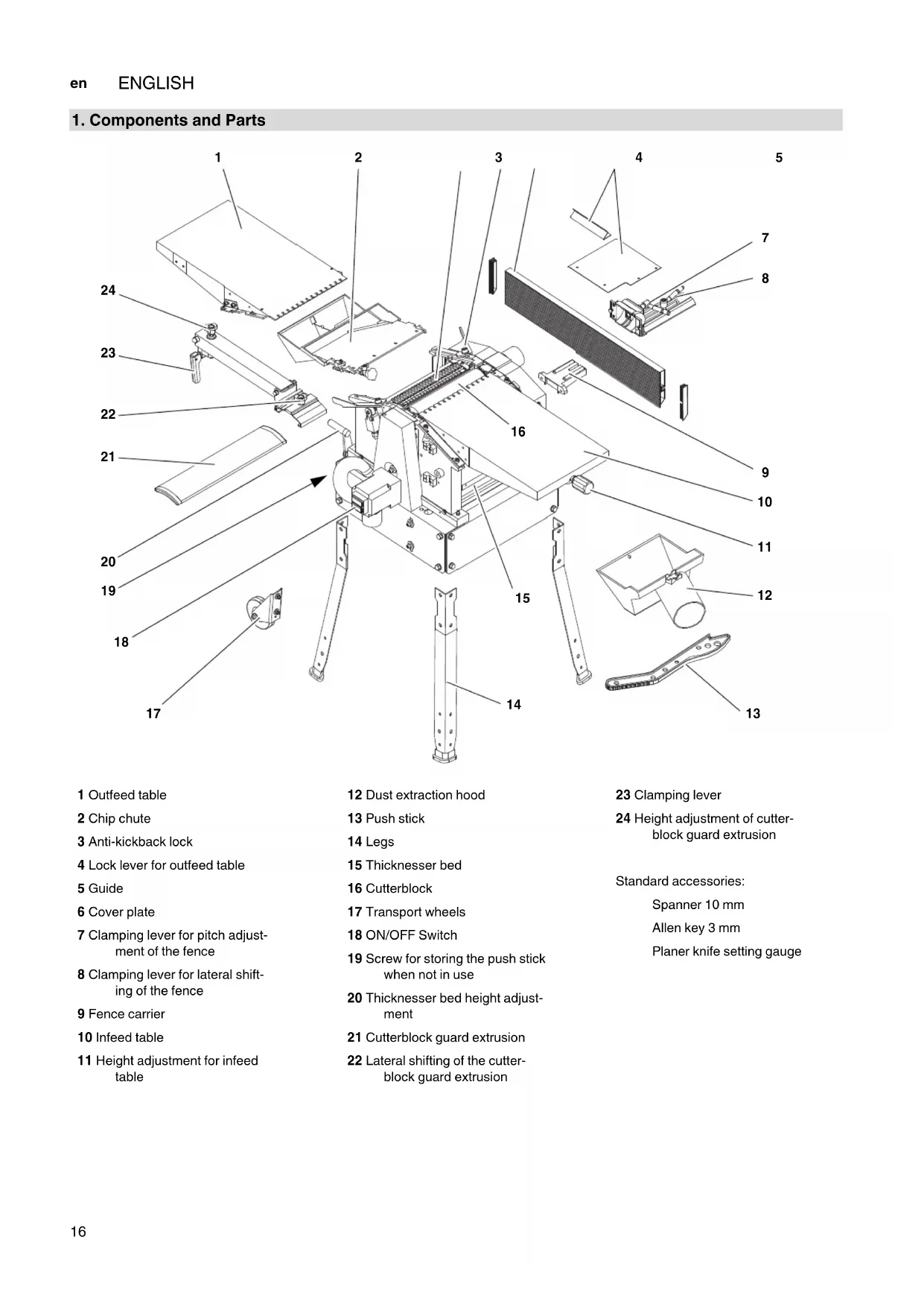
1. Components and Parts
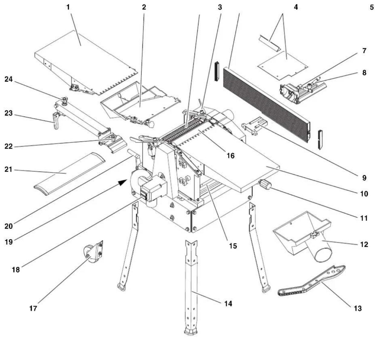
1 Outfeed table
2 Chip chute
3 Anti-kickback lock
4 Lock lever for outfeed table
5 Guide
6 Cover plate
7 Clamping lever for pitch adjustment of the fence
8 Clamping lever for lateral shifting of the fence
9 Fence carrier
10 Infeed table
11 Height adjustment for infeed table
12 Dust extraction hood
13 Push stick
14 Legs
15 Thicknesser bed
16 Cutterblock
17 Transport wheels
18 ON/OFF Switch
19 Screw for storing the push stick when not in use
20 Thicknesser bed height adjustment
21 Cutterblock guard extrusion
22 Lateral shifting of the cutter-block guard extrusion
23 Clamping lever
24 Height adjustment of cutter-block guard extrusion
Standard accessories:
Spanner 10 mm
Allen key 3 mm
Planer knife setting gauge
Contents
1. The thicknesser at a glance
2. Read first!
3. Safety
3.1 Specified Use
3.2 General Safety Instructions
3.3 Labeling
3.4 Safety Devices
4. Operating Controls
5. Assembly
5.1 Removal of shipping protection
5.2 Leg installation
5.3 Mounting the infeed table
5.4 Mounting the thicknesser bed height adjustment
5.5 Chip chute installation
5.6 Jointer fence installation
5.7 Connection to AC Power
6. Operation
6.1 Surface planer mode
6.2 Surface Planing and Edge Jointing
6.3 Thickness Planer Mode
6.4 Thickness Planing
7. Care and Maintenance
7.1 Removal and installation of planer knife
7.2 Feedgear Maintenance
7.3 Main Drive Belt Tensioning
7.4 Cleaning and Care of Machine
7.5 Transporting the Machine
7.6 Machine Storage
7.7 Maintenance Table
8. Repairs
9. Environmental Protection
10. Troubleshooting
11. Available Accessories
12. Technical Specifications
2. Read first!
These operating instructions have been presented in a way that will allow you to work quickly and safely with your machine. Here are a few tips to help you read these operating instructions:
- Read all of these operating instructions prior to commissioning the machine. Pay particular attention to the safety instructions.
These operating instructions are intended for people with basic technical knowledge in handling machines such as the one described here. If you have had no experience with machines of this kind, you
should initially work under the supervision of people with previous experience.
- Keep safe all documents supplied with this machine so that you can refer to them if required. Keep proof of purchase for possible warranty cases.
- Should you ever lend or sell the machine, make sure that any machine documents are passed on with it.
The manufacturer bears no liability for damage caused by non-compliance with these operating instructions.
Information in these operating instructions is designated as shown below:
Danger! Risk of personal injury or environmental damage.
Risk of electric shock! Risk of personal injury from electric shock.
Drawing-in/trapping hazard! Risk of personal injury by body parts or clothing being drawn into the rotating saw blade.

Caution! Risk of material damage.

Note: Additional information.
Numbers in illustrations (1, 2, 3, ...)
indicate component parts;
are consecutively numbered; and
correspond with the number(s) in brackets (1), (2), (3) ... in the neighbouring text.
Numbered steps must be carried out in sequence.
- Instructions which can be carried out in any order are indicated by bullet points () .
- List items are indicated by dashes (-).
3. Safety
3.1 Specified Use
This machine is intended for surface planing and thickness planing of solid woods. The permissible work piece dimensions must be observed (see "Technical Specifications").
The following tasks may not be carried out with this tool:
- Insertion work (i.e. any work that does not extend the full length of the work piece),
- Planing of cavities, pins or cut-outs,
- Planing of heavily curved wood with which there is insufficient contact with the holding and intermediate table.
Any other use does not comply with the intended purpose. Unspecified use, modification of the device or use of parts that have not been tested and approved by the manufacturer can cause unforeseeable damage!
3.2 General Safety Instructions
A thickening machine is a dangerous tool which can, due to operator carelessness, cause serious injury.

Caution!
When using power tools, the following basic safety measures must be taken to protect against electric shock, other injury or fire.
- When using this pump observe the following safety instructions to exclude the risk of personal injury or material damage.
- Please also observe the special safety instructions in the respective chapters.
- Where applicable, follow the legal directives or regulations for the prevention of accidents pertaining to the use of thickening machines.

General hazards!
- Keep your work area tidy - a messy work area invites accidents.
- Be alert. Know what you are doing. Set out to work with reason. Do not operate tool while under the influence of drugs, alcohol or medication.
- Do not operate the machine while under the influence of alcohol, drugs or medication.
- Consider environmental conditions: Keep work area well lighted.
- Prevent adverse body positions. Ensure firm footing and keep your balance at all times.
- Use suitable work piece supports to support the work piece when cutting long stock. Set the work piece rests to an appropriate height.
- Do not operate the machine near inflammable liquids or gases.
- This thicknessing machine shall only be started and operated by persons familiar with thicknessing machines and the dangers associated with the operation of thicknessing machines.
Persons under 18 years of age shall use this tool only in the course of their vocational training, under the supervision of an instructor.
- Keep bystanders, particularly children, out of the danger zone. Do not permit other persons to touch the tool or power cable while it is running.
- Do not overload tool - use it only within the performance range it was designed for (see "Technical Specifications").
- Do not plane deeper than 1/8 (3 mm).
- Turn power off if the tool is not used.

Danger! Risk of electric shock!
- Do not expose tool to rain.
Do not operate tool in damp or wet environment. - Prevent body contact with earthed or grounded objects such as radiators, pipes, cooking stoves, refrigerators when operating this tool.
- Do not use the power cable for purposes it is not intended for.
- Regularly check the power cable on the device and have it replaced by an approved expert if damaged.
- Regularly check extension cables and replace if damaged.
- When working out of doors, only use extension cables that are also approved for outdoors.
- Ensure the tool is disconnected from power before servicing.

Cutting hazard when touching stating cutterblock!
Always keep your hands well clear of the cutterblock.
Use suitable feeding aids, if necessary.
- Keep sufficient distance to driven components when operating the power tool.
- When in operation, do not reach into the dust collector or the cutterblock cover.
- To prevent accidental starting, always turn the machine OFF
after a power failure,
before unplugging or plugging in.
- Do not operate the tool without installed guards.
- Wait until the cutterblock has come to a complete stop, before removing jammed parts or small cutoffs, chips, etc. from the work area.

Cutting hazard, even with the block at standstill!
- Wear gloves when changing planer knives.
- Store the planer knives in a safe place and in such a manner that nobody can get hurt.

Drawing-in/trapping hazard!
-
Be careful that no part of your body or your clothing can be caught by and drawn into the machine. Do not wear neckties, gloves, garments with loose-fitting sleeves. Contain long hair with a hairnet.
-
Never attempt to plane any work pieces which contain
-
ropes,
strings,
cords,
cables or - wires, or to which any of the above are attached.

Risk of injury by work piece
kickback (work piece is caught by the rotating cutterblock and thrown back against the operator)!
- Operate machine only with a fully functional anti-kickback lock.
Always use sharp planer knives. Blunt planer knives may get caught in the surface of the work piece. - Do not jam work pieces.
- If in doubt, check work piece for inclusion of foreign matter (e.g. nails or screws).
- Never plane several work pieces at the same time. Risk of personal injury if individual pieces are uncontrolled caught by the cutterblock.
- Remove small cutoffs, scrap, etc. from the work area - when doing so, the cutterblock must be at standstill and the power cable unplugged.
- Ensure that when switching on (e.g. after servicing) no tools or loose parts are left on or in the tool.

Hazard generated by insuffi- personal protection gear!
- Wear hearing protection.
- Wear protective goggles.
- Wear dust mask.
- Wear suitable work clothes.
- When working outdoors wearing of non-slip shoes is recommended.

Risk of injury by inhaled wood
- Dust of certain timber species (e.g. beech, oak, ash) can cause cancer when inhaled. Use a dust collector whenever possible. The dust collector must comply with the data stated in the technical specifications.
- Ensure that as little as possible wood dust will get into the environment:
remove wood dust deposit in the work area (do not blow away!);
fix any leakages on the dust collector;
- ensure good ventilation.

Hazard generated by modification of the machine or use of parts not tested and approved by the manufacturer!
- Assemble tool in strict accordance with these instructions.
-
Use only parts approved by the equipment manufacturer. This applies especially to all safety devices (see spare parts list for stock numbers).
-
Do not change any parts.

Hazard generated by tools!
- Keep tool and accessories in good repair. Observe the maintenance instructions.
-
Prior to each use check the tool for any eventual damage: Before continuing to use the tool, safety devices, protective devices or lightly damaged parts must be carefully inspected for correct and proper operation. Check to see that all moving parts work properly and do not jam. All parts must be correctly installed and meet all conditions necessary for the proper operation of the tool.
-
Do not operate tool while under the influence of drugs, alcohol or medication. There is the risk of electrical shock. Ask a qualified electrician immediately to replace a damaged mains cable.
-
Damaged protection devices or parts must be repaired or replaced by a qualified specialist. Have damaged switches replaced by a service centre. Do not operate tool if the switch cannot be turned ON or OFF.
-
Keep handles free of oil and grease.

Danger from blocking work
pieces or work piece parts!
If blockage occurs:
- Switch machine off.
- Disconnect the mains plug.
3.wear gloves. - clear the blockage using a suitable tool.
3.3 Symbols on the machine

Danger!
Failure to observe the following warnings can result in serious injury or damage to property.

Read the operating instructions.
Always keep your hands well clear of the cutterblock. Keep sufficient distance to driven components when operating the power tool.
Height setting of thicken- nesser bed
Please see section 7.4 "Cleaning and care of the machine"!
Information on the nameplate:
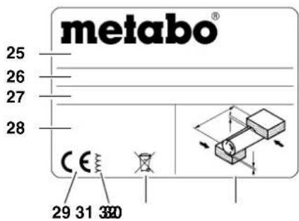
25 Manufacturer
26 Serial number
27 Machine designation
28 Motor specifications (see also "Technical Specifications")
29 CE mark - This machine conforms to the EC directives as per Declaration of Conformity
30 Year of manufacture
31 Waste disposal symbol - the machine can be disposed of through the manufacturer.
32 Permitted work piece dimensions
3.4 Safety devices
Anti-kickback lock
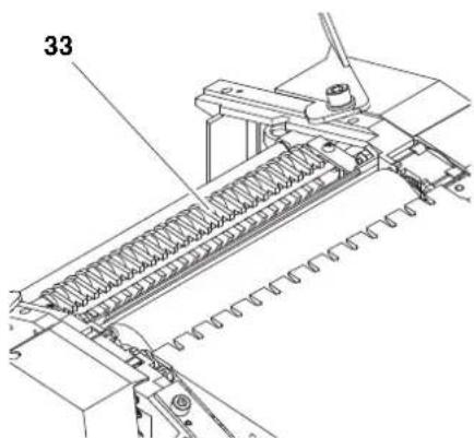
The anti-kickback lock (33) prevents the work piece from being thrown back against the operator by the rotating cut-terblock.
All fingers of the anti-kickback lock must end in a point on the underside.
All anti-kickback fingers must automatically return to their rest position (downwards).
Cutterblock guard extrusion
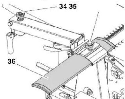
The cutterblock guard extrusion (36) prevents the rotating cutterblock from being touched from the top when surface planing.
After loosening the lock lever (35) the cutterblock guard extrusion is adjusted to the work piece width.
With the height adjustment screw (34) the cutterblock guard extrusion is adjusted to the work piece height. The height of the cutterblock cover extrusion can be adjusted from 0 to 85mm for surface planing.
For effective protection the cutterblock guard extrusion must always be set against the work piece. When guiding the work piece the hands slide over the cutterblock guard extrusion.
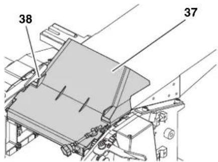
Chip chute
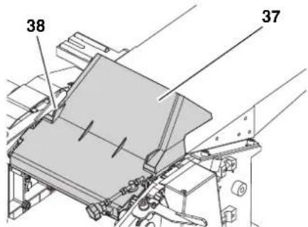
When thickness planing the chip chute (37) serves as cutterblock guard.
For this purpose the chip chute (37) is folded upwards and the adjustment screw (38) is turned anti-clockwise to the end position (chip chute is secured).
4. Operating Controls
ON/OFF Switch
- Switching on = press green switch.
- Switching off = press red switch.
Undervoltage relay
An undervoltage relay trips in the event of a voltage failure. This prevents automatic restarting of the machine when power is restored. To restart the machine after a power failure, the green ON switch button must be pressed again.
Overload protection
The planer/thicknesser has an integrated overload protection. It shuts the machine down if the motor heats up too much. To restart the machine:
- let motor cool down (approx. 10 minutes);
- press green switch button.
Infeed table height setting (when operated in surface planer mode)
With the height setting for the thicknesser bed the planing thickness (= thickness of the work piece after planing) is set when the machine is used for thickness planning.
One full turn of the crank changes the height position of the thicknesser bed by 3 mm.
- Per pass a maximum of 3mm material can be removed.
Work pieces of max. 160 mm thickness can be thickness planed.
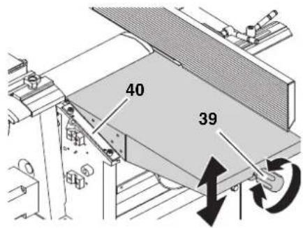
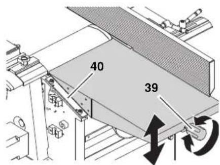
Infeed table height setting (when operated in surface planer mode)
With the height setting (39) for the infeed table the depth of cut is set when the machine is used for surface planing.
One graduation mark on the scale at the side of the infeed table (40) corresponds to 1 mm chip removal.
- Per pass a maximum of 3mm material can be removed.
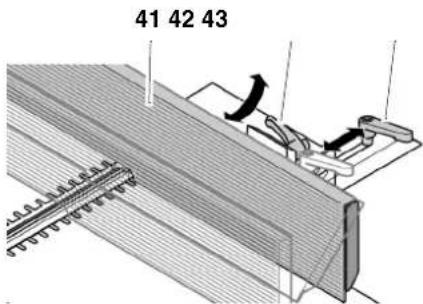
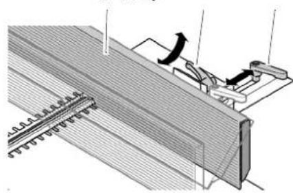
Fence profile
The fence profile (41) provides lateral support for the work piece when surface planing.
After loosing the clamping lever (43) the fence profile can be adjusted to the width of the work piece.
Loosen the lock lever (42) to tilt the fence extrusion to a maximum of 45^ .
5. Assembly

Danger!
Modification of the machine or use of parts not tested and approved by the manufacturer can cause unforeseen damage.
- Assemble machine exactly as per these instructions.
Use only the machine as standard equipment. - Do not change any parts.
Required tools
Spanner 10 mm
Spanner 13 mm
Philips screwdriver
Angle for 45^ and 90^
Allen key (different sizes)
5.1 Removal of shipping protection
- Remove foil protection from the thicknesser bed.
5.2 Leg installation
- With the help of a second person turn the machine upside down and place it on a suitable support.
-
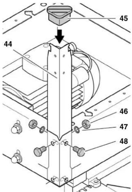
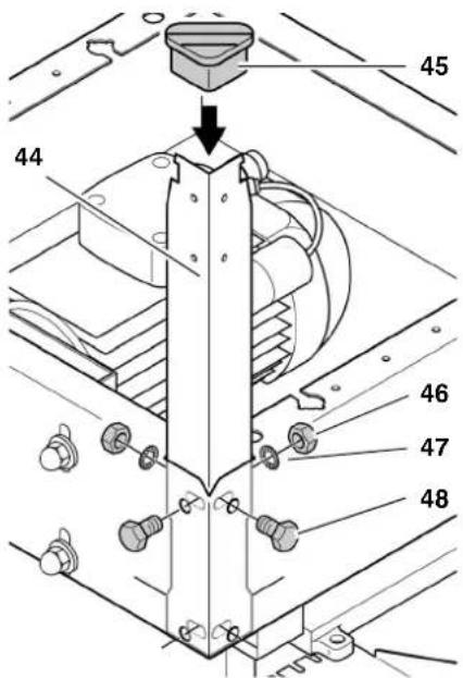
Fasten the four legs (44) to the inside of all corners of the machine:
-
Fit hexagon head screws (48) into holes from the outside;
place washers (47) and -
hexagon nuts (46) on screws and tighten.
-
Slide rubber feet (45) on legs.
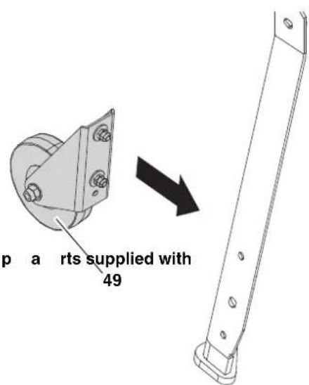
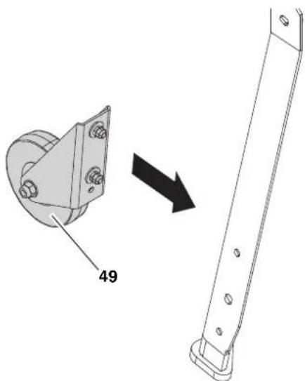
- Mount both transport wheels (49) to the legs on the side of the outfeed table with hexagon head screws, washers and hexagon nuts.
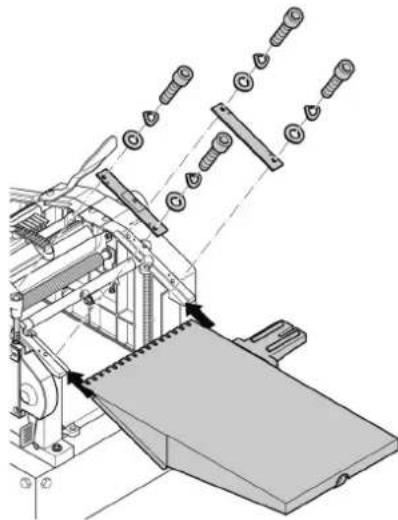
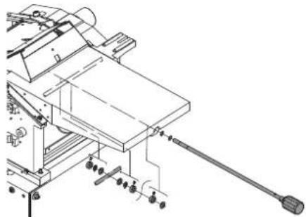
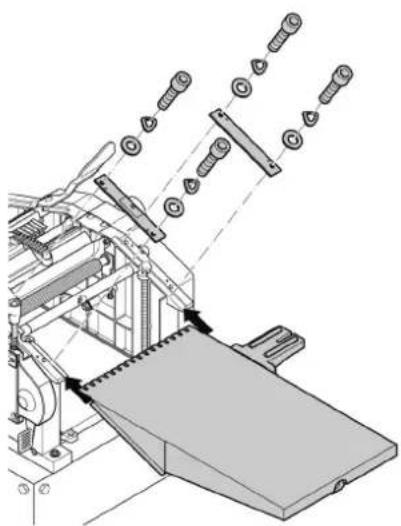
5.3 Mounting the infeed table
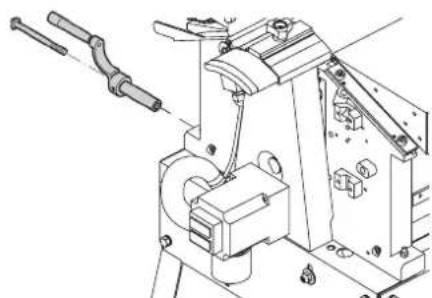
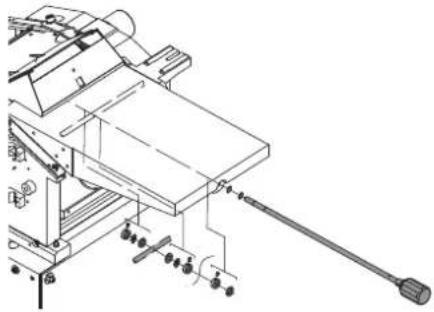
5.4 Mounting the thicknesser bed height adjuster
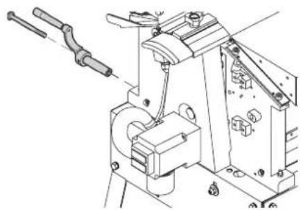
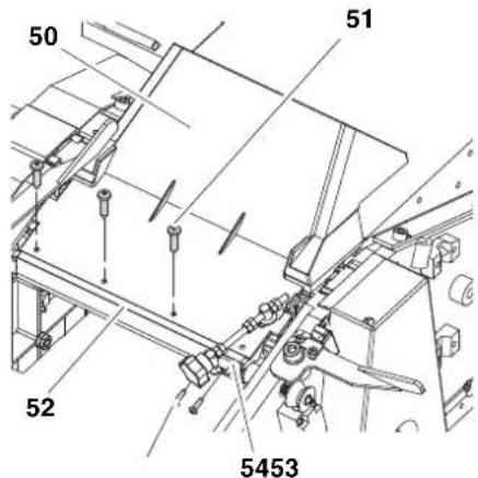
5.5 Chip chute installation
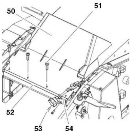
- Attacchchipch tapping screws (51) to the mounting profile (52).
- Attach adjusting screw holder (54) with two self-tapping screws (53) to the mounting profile (52).
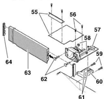
5.6 Fence profile installation
- Remove fence carrier support bracket (60) from fence carrier (57). Take care not to loose the two guide pins (61) in the fence carrier support bracket.
- Fasten fence carrier support bracket (60) with two hexagon head screws (59) to infeed table.
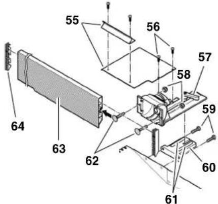
- Attach fence carrier to fence carrier support bracket again.
- Slide two carriage bolts (62) into the fence extrusion (63) and attach to fence carrier with two self-locking hexagon nuts (58).
- Fit extrusion end caps (64) to both ends of the fence extrusion.
- Screw the cover plates (55) together and fasten to fence carrier using two crosshead screws (56).
- Adjust the two set screws so that the positive stops of the jointer fence are set exactly to 45^ and 90^ (use try and metre squares).
5.7 Power-supply connection

High voltage
Operate in dry environment only. Operate machine only on a power source matching the following requirements (see also "Technical Specifications"):
- fuse protection by a residual current operated device (RCD) of 30mA sensitivity;
outlets properly installed, earthed or grounded, and tested;
5-wire three-phase outlets with neutral lead. - When a dust collector is used it must also be properly earthed.
Position power supply cable so it does not interfere with the work and is not damaged.
Protect power supply cable from heat, aggressive liquids and sharp edges.
Use only extension cables with a sufficient lead cross section.
Do not pull on power supply cable to unplug.
Check direction of rotation! (machines with 3-phase motor only):
Depending on the phase sequence the cutterblock may turn in the wrong direction. This can cause damage to the machine and work piece. It is therefore necessary to check the direction of rotation after initial commissioning and every time the machine is connected to a different outlet.
If the direction of rotation is incorrect the phases must be changed on the supply line or mains connection by an electrician.
6. Operation
The planer/thicknesser HC 260 can either be operated as surface planer or thickness planer:
6.1 Surface planer mode
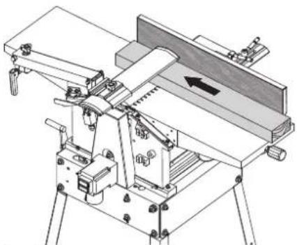
i Note:
Surface planing is used to level an uneven surface (=) jointing), for example the edges of a plank.
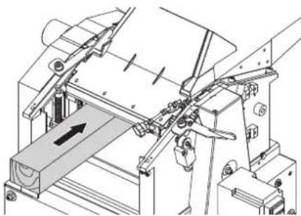
The work piece rests on top of the infeed table.
The work piece is cut on the underside.
The feed direction for the work piece is exactly opposite than that for thickness planing.
Work piece dimensions
| length width height | ||
| use push block(feeding aid) if less than 250 mm | max.260 mm | 5 mmmin. |
| use extra work piece supports or helper if over 1500 mm |
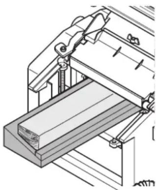
Preparation

Always unplug before servicing!
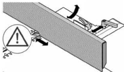
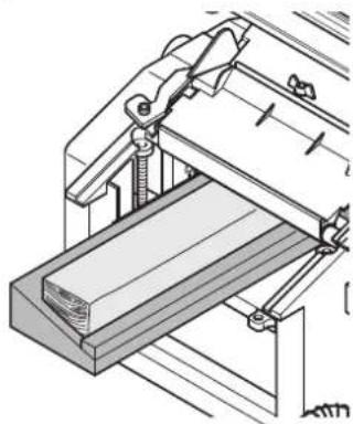
- Turn setting screw (65) clockwise to the end position.
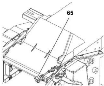
- Swing chip chute down.
- Turn both left and right lock lever outwards.
- Place outfeed table (66) on machine - both pins on the machine housing must engage in the lower slots of the outfeed table guide.
i Note:
The pins must trigger the end switch. Only then the machine can be switched on.
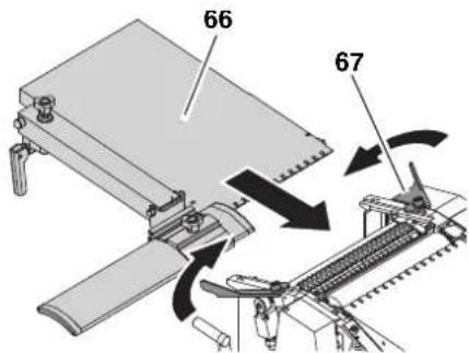
- Secure outfeed table (66) with both lock levers (67).
- Set the infeed table to 2.0 to 2.5mm by turning the height adjustment.
- Crank thicknesser bed up to 120 mm height.
-
Place dust collector connector (this is not the chip chute mentioned in step 1!) below the infeed table into the machine. Observe correct position of the dust collector connector: suction port points outwards;
-
slide dust collector connector in until the point of intersection of shaft and axis below the infeed table (arrow) is exactly above the matching seat of the dust collector connector.
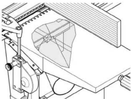
- Crank the thicknesser bed carefully up to secure the dust collector connector in position.
- Connect a suitable dust collector to the suction port of the dust collector connector.
- Cover the cutterblock with the cutterblock guard extrusion.

Note:
The dust extractor hood must be mounted. The dust extractor hood covers the knife shaft from below and must activate the limit switch to enable the machine to be switched on.

Danger!
Some types of wood dust (e.g. oak, ash) may cause cancer when inhaled: Use a suitable dust extraction unit when working in enclosed spaces:
Fitting the outer diameter of the suction port (100 mm);
air flow volume ≥ 550 m/h;
vacuum at suction port of thicknesser ≥ 740Pa
air speed at suction port of thicknesser ≥ 20m / s

Caution!
Operation without a dust collector is only possible:
Outdoors;
- if only a minimum of chips is generated (with narrow stock and little chip removal);
with dustrespirator.
6.2 Surface Planing and Edge Jointing

Danger!
Risk of serious personal injury by rotating cutterblock! Always cover the part of the cutterblock
that is not covered by the work piece with the cutterblock guard extrusion. Adjust the cutterblock guard extrusion exactly to the dimension of the work piece.
-
Check the function of the cutter-block guard extrusion. Push the cutterblock guard extrusion downwards and release. After releasing the cutterblock guard extrusion has to spring back automatically to the set position. Do not operate the device with a defective cutterblock guard extrusion.
-
Never reach with your hands under the cutterblock guard extrusion when guiding the work piece!
Use a feeding aid (push block) when planing small work pieces, which can not be guided with a sufficient safety distance to the cutterblock.
Use the jointer fence when edge jointing to have safe lateral support and guiding. Use an auxiliary fence when planing thin or narrow stock, to have your hands at a sufficient safety distance to the cutterblock.
Use a stop block behind the work piece for set-in work, to keep the work piece from being thrown back against the direction of feed.
Use a work piece support (e.g. roller stand) to keep long stock in balance.
- Do not pull the work piece back over the unguarded cutterblock!
Use if necessary: Dust collection device (optional accessory); sliding wax to enhance the gliding of work pieces across the infeed and outfeed table.
-
Assume proper operating position: on the switch side; head-on to the machine;
-
Set jointer fence as required.
- Set depth of cut with starknob screw (68) on the infeed table.
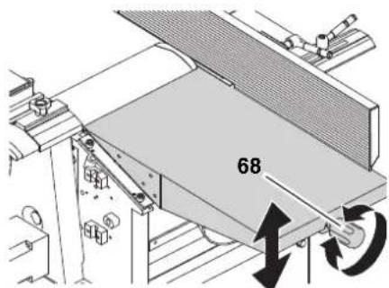

Note:
The machine can remove 3mm maximum in a single pass. This measure, however, shall only be used:
with very sharp planer knives;
for soft woods;
- if the full planing width is not utilized. Otherwise there is a risk of overloading the machine.
It is best to make several passes to bring the work piece down to the desired thickness.
- Place work piece against jointer fence (if required, use auxiliary fence).
-
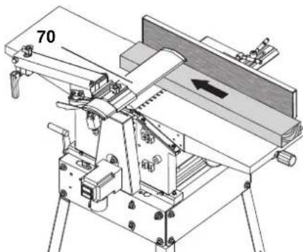
Adjust cutterblock guard extrusion:
-
Planing small edges (jointing): Push the cutterblock guard extrusion (69) laterally to the work piece.
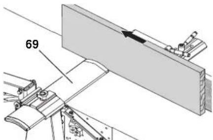
- Planing wide surfaces: Lower the cutterblock guard extrusion (70) from above onto the work piece.
- Switching on the motor.
- Push the work piece straight across the infeed table. Keep fingers together and guide work piece with the flat of your hand. Exert down
ward pressure on the work piece only in the infeed table area.
- Switch machine off if no further thick-nessing is to be done immediately afterwards.
6.3 Thickness Planer Mode

Note:
Thickness planing reduces the thickness of a work piece with one already planed surface.
The work piece is fed through the thicknesser.
The surface already planed flat rests on the thicknesser bed.
The work piece is cut on the upper side.
The feed direction for the work piece is exactly opposite than for surface planing.
Work piece dimensions
| length width height | |
| 200 mm min. - 4 mm | min. |
| use extra work piece supports or helper if over 1500 mm | max. 260 mm |
| max. 160 mm |
Preparation

Danger!
Always unplug before servicing!
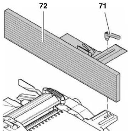
- Loosen clamping lever (71) and remove fence (72).
- Turn both left and right clamping lever (74) outwards.
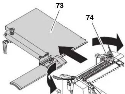
-
Remove outfeed table (73).
-
Swing chip chute (77) up over the cutterblock.
- Turn setting screw clockwise to the end position. The guard cannot be opened.
- When operating with a chip extraction unit: Remove wing nut from the chip chute (77). Place the chip extraction hood (75) on the chip chute (77).
- Secure chip chute (77) with the wing nut (76).
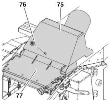

Note:
For thickness planing the chip chute (77) serves as cutterblock cover. The chip chute must activate the limit switch, otherwise the machine cannot be started.
- If a dust collector is to be used, connect the dust collector connector's suction port (75) to a suitable dust collector.

Danger!
Some types of wood dust (e.g. oak, ash) may cause cancer when inhaled: Use a suitable dust extraction unit when working in enclosed spaces:
Fitting the outer diameter of the suction port (100 mm);
Air volume ≥ 550m^3 /h
vacuum at suction port of thicknesser ≥ 740Pa
air speed at suction port of thicknesser ≥ 20m / s

Caution!
Operation without a dust collector is only possible:
Outdoors;
- if only a minimum of chips is generated (with narrow stock and little chip removal);
with dust respirator.
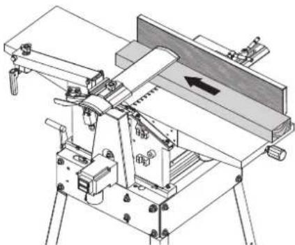
6.4 Thickness Planing

Danger!
Entanglement hazard by the rotating feed rollers! Do not reach into the machine! Use a feeding aid (push stick) if you want to feed short stock into the thicknesser.
- Do not jam work pieces. Risk of kickback.
- Remove stuck stock only after motor has come to a complete stop and machine is unplugged.
Guide a work piece on the outfeed side if it has been fed so far into the thicknesser that it can no longer be safely guided from the infeed side.
- Do not thickness plane more than two work pieces at the same time. In this case feed both work pieces near the outer edges of the thicknesser bed.
Use if necessary: Dust collection device (optional accessory); sliding wax to enhance the gliding of work pieces across the infeed and outfeed table.

Caution!
There is a limit switch inside the machine. Take care not to damage the limit switch when feeding work pieces.
- Assume proper operating position:
on the switch side;
head-on to the machine;
- Set planing thickness with the crank.

Note:
The machine can remove 3mm maximum in a single pass. This measure, however, shall only be used:
with very sharp planer knives;
for soft woods;
if the full planing width is not utilized.
Otherwise there is a risk of overloading the machine.
It is best to make several passes to bring the work piece down to the desired thickness.
- To thickness plane stock which surfaces are not parallel, use suitable feeding aids (make fitting templates).
- Switching on the motor.
- Feed work piece slowly and straight into the thicknesser. It will then be automatically fed through the thicknesser.
- Guide work piece straight through the thicknesser.
- Switch machine off if no further thick-nessing is to be done immediately afterwards.
7. Care And Maintenance
Danger!
Prior to all servicing:
- Switch off the machine.
- Disconnect the mains plug.
- Wait until machine has come to a complete stop.
Replace defective parts, especially of safety devices, only with genuine replacement parts. Parts not tested and approved by the manufacturer can cause unforeseen damage.
After all servicing:
Put back into operation and check all safety installations.
Make sure that no tools or other parts remain on or in the machine.
Repair and maintenance work other than described in this section should only be carried out by qualified speciaIists.
7.1 Replacing Planer Knives
i Note:
Blunt planer knives are recognizable by:
reduced planing performance;
- increased risk of kickback;
- motor overloads.
Danger!
Risk of personal injury by cuts from the planer knives! Wear gloves when changing planer knives.
To remove the planer knives:
- Disconnect the mains plug.
- Remove fence.
- Raise cutterblock guard extrusion fully and pull extrusion fully outwards.
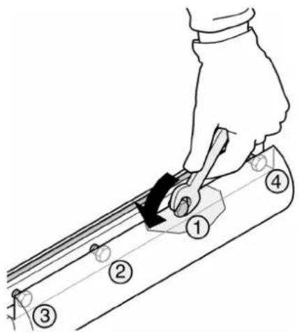
- Turn the four hexagon head screws of the planer knife lockbar fully in (wear gloves!).
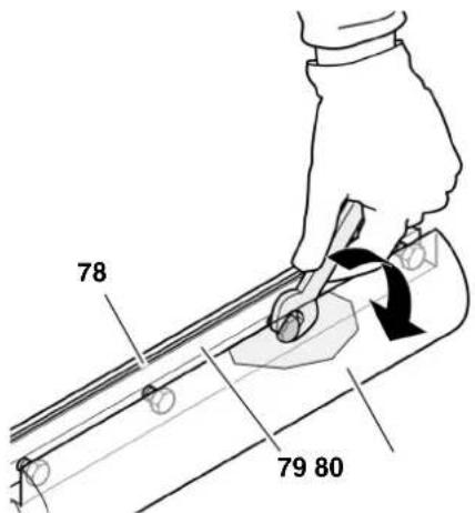
- Remove planer knife lockbar (79) with planer knife (78) from the cutter-block (80).
- Clean all surfaces of cutterblock and planer knife lockbar.
Danger!
Do not use cleaning agents (e.g. to remove resin residue) that could corrode the light metal components; the stability of the light metal components would be adversely affected.
To install the planer knives:
i Note:
If you use planer knives having an edge on both sides you simply need to reverse the knives, provided the other edge is sufficiently sharp.
Danger!
Use only suitable planer knives (see "Technical Specifications") - unsuitable, incorrectly mounted, dull or damaged planer knives can work loose, or
increase the risk of kickback considerably.
Always replace or reverse both planer knives.
Install planer knives using only genuine replacement parts.
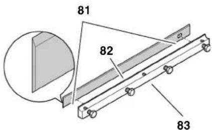
7. Place fresh planer knife on planer knife lockbar as shown.
Both pins of the planer knife lockbar must fit into the holes (81) of the planer knife.
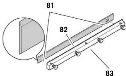
- Place the planer knife lockbar (83) with the planer knife (82) into the cutterblock. Ensure that the knife does not slip off the pins of the planer knife lockbar.
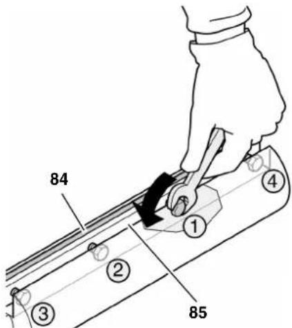
- Turn the four hexagon head screws in the planer knife lockbar out, until lock bar (85) and knife (84) can still just be moved along the axis of the cutterblock.
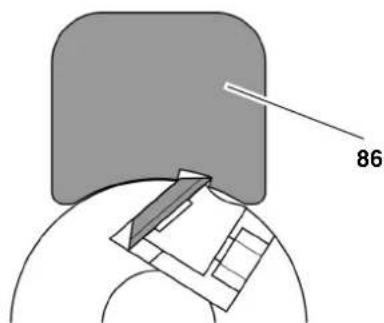
- There are two ways to check the projection of the knives:
With the setting gauge (86) (under the prevailing regulations governing safety at work this must be supplied with the machine).
- Place planer knife setting gauge on cutterblock as shown. The knives must project so much that they touch the setting gauge.
This check must be performed on both planer knives and at both ends of the cutterblock.

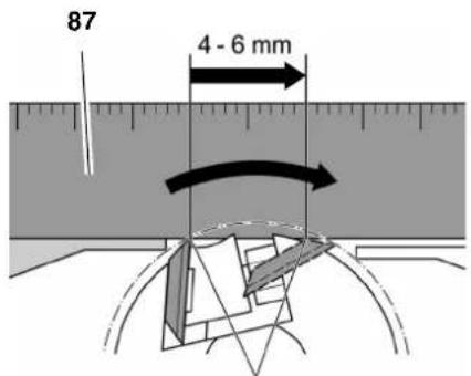
Use an aluminium straightedge (87) (this is more precise than using a setting gauge).
- Place aluminium straightedge as shown over outfeed table and cutter-block.
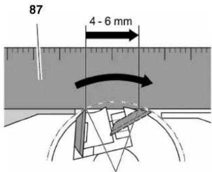
Turn cutterblock by hand one turn against the direction of feed.
The planer knives are set correctly if the straight edge is moved forward 4 to 6mm by the turning cutterblock. This check must be performed at both ends of the cutterblock.
- To set the knife projection, turn the grub screws in the planer knife lockbar with a 3 mm Allen key as required.
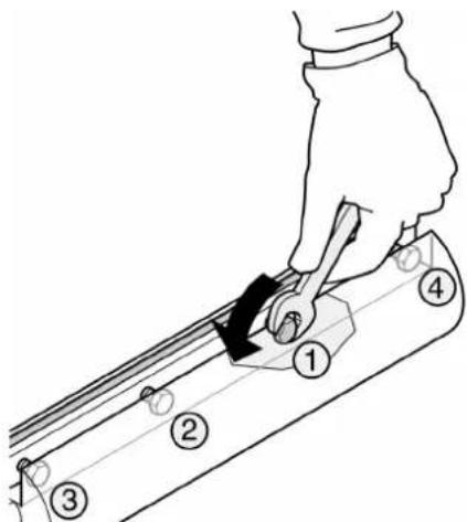
- To tighten, turn the four hexagon head screws of the planer knife lockbar fully out. To prevent distortion of the planer knife lockbar start with the screws in the centre, then tighten the screws closer to the edges.
Danger!
- Do not extend tool when tightening the screws.
-
Do not tighten bolts by striking the wrench.
-
Return cutterblock guard extrusion to its starting position.
- Mount fence.
7.2 Feedgear Maintenance
- Disconnect the mains plug.
- Unscrew the two nuts of the drive cover and remove the drive cover.
- Remove chips and dust with dust collector or brush.
- Apply a light coat of care and maintenance spray to roller chain and shaft and axle bearings (do not use oil!).
- Replace the drive cover and secure with the two nuts.
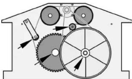
7.3 Main Drive Belt Tensioning
- Disconnect the mains plug.
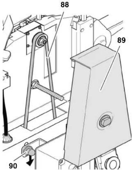
- Unscrew the nut of drive belt cover and remove cover (89).
- Check belt tension with thumb pressure. The drive belt (88) should not give more than 10mm in the centre. If the drive belt requires tensioning:
- Loosen the four motor mounting screws by approx. one turn.
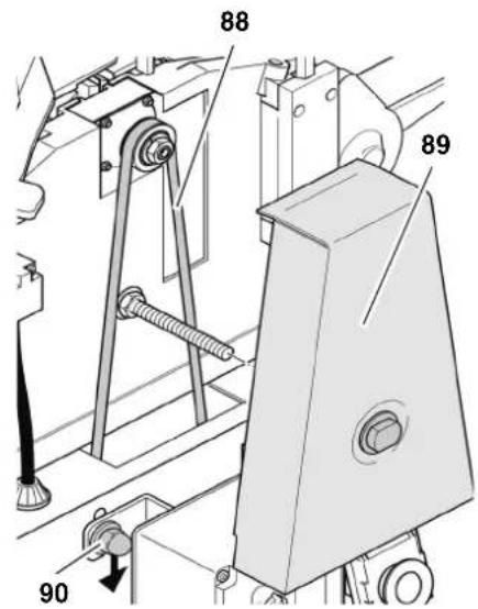
-
Push motor down to tension belt.
-
When belt tension is correct tighten motor mounting screws (90) crosswise.
- If necessary, remove chips and dust with dust collector or brush.
- Put belt cover back on and secure with nut.
7.4 Machine Cleaning and Care
- Disconnect the mains plug.
-
Remove chips and dust with dust collector or brush from
-
cutterblock;
height-setting mechanism of cutterblock guard extrusion; - thicknesser bed spindles;
-
thicknesser feed drive.
-
Apply a light coat of care and maintenance spray to the following components (do not use oil):
-thicknesserbedspindles;
height-setting mechanism of cutterblock guard extrusion.
- Apply a light coat of anti-seize compound to infeed table, outfeed table and thicknesser bed.
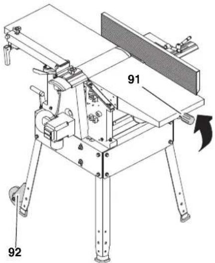
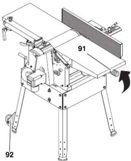
7.5 Transporting the Machine
The machine can be transported by one person. Tilt the machine at the height adjustment (91) until the machine stands on the transport wheels (92) and move it on the transport wheels.
7.6 Machine storage
Danger!
- Disconnect the mains plug.
- Store machine in such manner that
it cannot be used or tampered with by unauthorized persons, and
that nobody can get hurt while the machine is turned off.

Do not store machine unprotected outdoors or in damp environment.
7.7 Maintenance Table
The checks and procedures described in this section are an aid to safety! Should there be faults evident on any of the mentioned components, the machine must not be used until these faults have been remedied in a workmanlike manner.
| Prior to operation | |
| Anti-kickback lock | Check: - mobility of anti-kickback fingers (must fall down by their own weight) - points of anti-kickback fingers (not rounded) |
| Planer knives Check: - tight seat - sharpness - general condition (no notches, etc.) | |
| Inside of machine | Remove: - chips - sawdust |
| Threaded rods (height adjustment) | |
| Dust spout (when working without dust collection) | |
| Outfeed roller Check: - coating undamaged? - is stock properly transported? | |
| Infeed and out-feed table | - apply light coat of anti-seize compound |
| Monthly (if used daily) | |
| Threaded rods (height adjust-ment) | Apply a light coat of care and mainte-nance spray |
| Infeed and out-feed table | Check alignment, correct if necessary |
| Power supply cable | Check for damage, if necessary have replaced by a quali-fied electrician. |
8. Repairs

Repairs to electrical tools must ONLY be carried out by qualified electricians!
Contact your local Metabo representative if you have Metabo power tools requiring repairs. See www.metabo.com for addresses.
You can download a list of spare parts from www.metabo.com.
9. Environmental Protection
All packaging materials are recyclable. Scrap power tools and accessories contain large amounts of valuable resources and plastics that can be recycled.
The instructions were printed on chlorine-free bleached paper.
10. Troubleshooting

Before carrying out any fault service or maintenance work, always:
- Switch machine off.
- Wait until the saw has come to a complete stop.
- Disconnect the mains plug.
Cutting hazard when touching the rotating cutterblock!
Unintentional startup of the machine may lead to serious injuries.

Shortly after working the planer knives may be hot - Let the device cool down before rectifying any malfunction.

After each malfunction rectification: Put back into operation and check all safety installations.
Motor does not run:
- Undervoltage relay tripped by temporary voltage failure.
- Start again.
- No mains voltage.
- Check cables, plug, outlet and mains fuse.
-
Motor has overheated, e.g. due to blunt planer knives, overloading or chip buildup.
-
Remove cause for overheating and allow to cool down for
approx. 10 minutes, then start again.
-
Contact pins of outfeed table or dust chute have not engaged in the limit switch.
-
Correctly install outfeed table or dust chute, respectively. If necessary, adjust contact pins.
- When thickness planing: Check if the setting screw of the chip guard is turned to the end position and correct if necessary. Only then the contact switch is activated and the machine can be switched on (see chapter 6.3 "Operation as thickness planer").
- When surface planing: Check if the chip extraction guard is mounted correctly. Only then the contact switch is activated and the machine can be switched on (see chapter 6.1 "Operation as surface planer").
Performance lessens
- Planer knives blunt
Install sharp knives. - Drive belt slips
- Re-tension drive belt
Planed surface not smooth
- Planer knives blunt
Install sharp knives. - Planer knives blocked by chips
- remove chips.
- Moisture contents of work piece too high
Dry work piece.
Planed surface cracked
- Planer knives blunt
Install sharp knives. - Planer knives blocked by chips
- remove chips.
Work piece was planed against the grain - Plane work piece in opposite direction
- Too much material removed in one pass
- Make several passes at less depth of cut.
Feed rate too little (thickness)
Resin buildup on thicknesser bed Clean thicknesser bed and apply light coat of anti-seize compound.
Feed rollers stiff
Repair feed rollers.
- Drive belt slips
- Re-tension drive belt
Work piece jammed (thicknessing)
- Too much material removed in one pass
Make several passes at less depth of cut.
11. Available Accessories
For particular jobs you will find the following accessories at your specialist dealer - the images can be found at the beginning of these operating instructions:
A Extraction adapter For connection to a chip extraction unit
B Three- roll stand For precise guidance of long work pieces
C Planer knives For planing of wood pieces (can be resharpened)
D Planer knives For planing of wood pieces
E Planer knives For planing of wood pieces (carbide, can be resharpened)
F Cutter bar conversion set For retrofitting the planer knives
G Planer knife setting device For problem-free setting of the knife projection.
H Lubricant WAXILIT For good sliding quality of the wood on the support table
I Maintenance and care spray For the removal of resin residue and for preservation of metal surfaces
12. Technical Specifications
| HC 260 C WNB | HC 260 C DNB | ||
| Motor 50 | Hz | ||
| Voltage V 230 400 | |||
| Fuse protection | A 16 | 16 | |
| No-load speed | |||
| Motor | min-1 | 2700 | 2700 |
| Cutterblock | min-1 | 6500 | 6500 |
| Feed rate, thickness planing | m/min | 5 | 5 |
| Planer knife dimensions | |||
| length | mm | 260 | 260 |
| width | mm | 18.6 | 18.6 |
| thickness | mm | 1 | 1 |
| Machine dimensions | |||
| length (overall across infeed and outfeed table) | mm | 1110 | 1110 |
| width | mm | 575 | 575 |
| height | mm | 940 | 940 |
| Machine: complete with packaging | kg | 76.0 | 76.0 |
| Machine: ready for operation | kg | 71.0 | 71.0 |
| Noise emissions during surface planing according to EN 61029-1* | |||
| Emission sound pressure level LpA (under load) | dB (A) | 84.1 | 84.1 |
| Sound pressure level LWA (under load) | dB (A) | 91.3 | 91.3 |
| Measurement uncertainty KWA | dB (A) | 3 | 3 |
| Noise emissions during surface planing according to EN 61029-1* | |||
| Emission sound pressure level LpA (under load) | dB (A) | 87.6 | 87.6 |
| Sound pressure level LWA (under load) | dB (A) | 94.1 | 94.1 |
| Measurement uncertainty KWA | dB (A) | 3 | 3 |
| Work piece dimensions | |||
| max. width | mm | 260 | 260 |
| max. height (thickness planing) | mm | 160 | 160 |
- The values stated are emission values and as such do not necessarily constitute values which are safe for the workplace. Although there is a correlation between emission levels and environmental impact levels, whether further precautions are necessary cannot be derived from this. Factors influencing the actually present environmental impact level in the workplace include the characteristics of the work area and other noise sources, i.e. the number of machines and other neighbouring work processes. Also, permissible workplace values may vary from country to country. This information is intended to assist the user in estimate of hazards and risks.
Risque de happenment!
Risk for indragning!
Fare for forbrenning!
7.5 Transport of maskinen
7.6 Opbevaring af maskinen
7.5 Transport of maskinen
Reservedelslicer kan downloads pa www.metabo.com.
9. Miljøbeskyttelse
Fare for forbreading!
YnodEiE:
ZmuIaepwauatikc nInpo-
phiic.
- Oi apiooi otic eikovc (1, 2, 3,...)
unOdeltaKvovu eva Eapntnata,
- napatiEvtau με δiaoxikn aovoa apiθμon,
avaepovtau o6 oxetikouc apiouoc evtoc npevtheewv (1), (2), (3) ... 0to npapanleupo keIevo.
O obnyie xepiouo, otiooe npene va tnpn0i ia oipap o n c evpyewvivai apiunneves.
Oi oyniec xepiaou onou dev aataeitai n npnon ouykepueevns eipac ponc evspyeiv, exouv ano mnpoota touc ia teia.
Oi Iiotc exouv ano npooTra ia nauλa.
3. Aσφάλεια
3.1 Xpno a e Tov oKOIO nPooopioou
H oukeun npoBaeTai yia to naavi oma eniphiewkai naviogna maxouc Eulou maio. Ppei va npouvtai o npoBaeTouevic diaotaoic twkatapyaocevwv teaxiwv (Bene TExviKa OToixia).
OlaokoloueCepaieCdeltaptentau vaekelouvtai eautn touokeun:
Eviaeepyaic (nλ. kαθε εpyaia nou δεν εκτελειτai oε oλo to μnkoc tou katepyaçóevou τμaxiou),
- Iπáviσμα εσoχων, μόρσων ἡ εγκο-πων,
Iiavua 1iaitepa kaunuawv uawv, ta onoia dev exouv kavoTnTkiE npn mTo TpaneU unOdoxnc kal to eaoio panec.
Kahe aAnxpnEivalnEvdeltaIy
evn.HnnpoBentoueynxpn,oi
etatponc TNC oukeunc kaowc kai n
xpn EApntmuWv ta onoia dev
exouv Exyxei kai Ekypi0ei anotov
kataokvaon mnoei va exouw wc anot
TeAeoga anpObetaenTc Znueic!
3.2 Evikec uno8eileic aphiia
H mnxavik nIavn eivai eva etiikivv oepyaiao, nou npoei oe nepiTTOWe Tnoaiotntac va npokaloei oobapouc tpaupatouc.
# np
Kata tn xphon nAektpikw evyaaleiwv yia npoostacia ano nAektpontnxiia, tpaumatioouc kalnpkayia npenla v npooEETa akoloutheta aoika metpa aosphaeiaac.
IpooeEeKataTnXpnoTns ouokeuHcTic EIOuevEc UTOBdEIEa aOpaaleia yia va anokAioTouv Kivduvoia Tpaumatoo n ulikec ZnmuEc.
TnpieTe Tc EidiKec unObeiEic aoaaleiaocota ekaoTote Kefdaia.
TnpnoTe Evdoevec voo0etikec diataeic n kavoea anotpomc atuxnmuawkatao xepio mnxavikw nnavw.

Tevikoi kivduovl!
-
DiatnpnoTe to xwpo epyaioac oac kaH kataoTaN - n ataEla oTo xwpo epyaioac mnopei va odynnoe i atuxnata.
PpEe va exTe TETaEv nTn npOoxn oac. Ppaayatonoiote tic SwoTe c evpyiec. H epyaia pEe Tvi na ppaatonoietai e foVnon. Mny kavete xpon tnc ouakeunc eav dev eioe ouykevtpwEvol.
Mny kavete xpno nts ouokeunc otav piokeote uno tnv empeia oivonteumuatoc, vapkwtkwovouwv npapakwv.
AaBETe unOytnTc nepiBaAovtkeC EINbpaoEIC. PovTiote wTe va unapxIo kataaAhoC wfioHoc.
Anouyte tvavtkavovikn taon tou oomegaoc. Povtiote yia tv aoaa n taoan kai diatnpite ava nca stiyun tvlopponia.
Xpnooioite kataaannec eniavvce anotheoc otav ta teuaxia katepyaiaac exouv eyaol nkoC. Tonoetntote tic eniavcnc ano- 0eonctwv katepyaoevuv Teaaiow oTo kataaanno uosc.
Mny kavete xpon autnc tns ouakeunic nnoiov eouktwv uypw n aepiwv.
H oukeun autn eitpenei tai va tiethai oE aeitoupyia kai va xpoioi- pnoieita movov ano atoua, ta onoia exouv eoikewthetai otxpnon mnxavikw navovkai ta onoia exouv av a naoa otiym eniyvwn twv kivdvuvw tnc xpnons. Atoja katw twv 18 etw vntpeitei tai va xpoioonoiovu auto to epya Ieio mvo stn laio tn cenayveImuatikc ektaideueon tout no tv EiBaeyneknaideutn.
Mny eipene Tc avapodoug, Eikca ta naia, va nnaouv otnv npoxkivouou. Mny ahe TE OTN diapkeia TnC aeitoupyiac va ayicov aaataoTa epya- Iio n to kaawdo ngktpkoikoukTou.
Na yivea unepoTn Tc oukeunc -xpon Tc entpenr ta mvo oiaotwv duvatotntwiooc nov avapoeovtalota "Texvka oixia".
Mny navapetne oE a0c t e p o TnC 1/8 ivToaC (3 mm). -
Θεοτε to πρίονι εκτός λειουργίας, εὰν δε χρομισοιεῖαι.

Kivduoc ano to nAekTpi
!
Mny ekTeTe Tn ouakeun otn
bpoxn.
Mny kave Te xpon tnc ouakeunc
oUypo npiaalov
Antofoyete kata tyn evyaia me autnVtn oukeunTyn eanf tou oomegaatoC ME YEWUEVAePn (x. x. oomegaata kalopiep, eTaalikouc oWlnvcs, nEKTpiKc KOUivcs, yuyia).
Mn xnpouoieTe To kaawio Toudeltaou aokota.
ELeyxETAKtkaTo kalwdoO uVdeltaoc Tou nAekptkoEpyaaiou kai avaote OE iepintwn Znmuac Tnv avtkataoan Tou e evav avayvwpiouevo Aektpofoyo.
EeYxTe Ta kaiwdi eNekTaOnc (maalavteCec) taKtika kalavtka-thotate Ta,otav exouv cnmu.
Otauevpyaéothe to nektpko evyaleio oto unaitheta xpouonoi eite navtote kawbiaeketaoc (maavtec) nou exouv ykpiEi yia xpnon oEewotepikoucxwpouc.
Ipiiv nTv evapEn epyaowv ovtnponc 3ebaiomegaite, otn ouokean6ev ivai ouvdeltaevn me to nKtpiko pua.

Kivduvo Koiipatoos Aoyu nC ME TOV NEPIOPTPEOevo muaxapiw!
Na tnpelte navtoe eapkn ano- staon ano tov aovaxaipwv.
XpnoiOnoiTeEvdsxouevuoc katalnnlaeota pOpoosiauc uikou.
Kpatate navta enapkn ano- staon ta eapntma tou laubavouv kivnon otn diapkeia tns leitoupyias.
Mny Eioayete Ta xepia Oa Kata Tn diapkeia Tnc λeitoupyiac OTN diatae avappofoqos Pokavi- diw n oTo kaUmuTou aEova maXaipivv.
Tia va anofoyete Tnv akouia ekkiynon tns ouokeun, npenla va obnveTe navtoe tn ouokeun:
- a n o diakonn pεuμatoc,
πpiv to rpáβηγμa n thv ειαγωγn tou φις tou kalωδiou.
Mny teTtE OE 5eitoupyia To epya- 5io av 6ev exouv tooetnthetai o i diataeic npootaoiac.
IepuveTe MeXpO aEvoc Maayai piWv va akvntooine Ipotou va anoakpuveTe maykwmeva kouma
Tia n mikpa koumaia katepyaocevou teaxiou, unolemuata Eulou K.a. ano to xwpo epyaiaac.

Kivduvo Koiipatoc kal oToV tonoinevo aEova maXaipw!
Xpnooioiote yavta kata tv avtikataotaon tou maaxapiou nla-vns.
ΦuλaTe ta μαχaipia πλavnc katá Teteiov tpònto, wotε va μη μπopei kaveic va tpaμaṭiσtei.

Kivduvoaaykwaatoc!
IpooEkTe kata Tn diapkeia Tns aeitoupyiac va un npopeoov va tpaBnxtouv npoc ta nca oae nTou owatoc n avtikeeva maiz me To katepyaOevo Teaxio. Na un opate ypaBATEc, un opate yaVTia kai un npopate evdujata u Eupuxwpaavikia.Eav exETe kaPaaAia,va xpnaionoiite onwohnote eva bixtu npootaia cTwv aAawv.
Na nV nAviCtE nTo KAtepyao- eva Teaxia, oTa onoia unapxouv
- oxovla
- kλωστες
Tavies
-kaλωδla n - oupuata, n ta onoia nepiauaivouv tetoia.

Kivduoc ano tnv onioospok (klotonma) katepyaζóevwv
Teuxw (to katepyafo Teau xio apnaceiao tov aova maxai piowkai Ekaovtietai npoc Tn epiouxipot)!
Na 3pva3eote movo e a0phialeia kawtoaatoC nou aetoupyei anpo-OKoTTa.
Na xnpaonoei Teavtoe Kofepa maxaiipia nAvnc. Maxai- pia nAvw vou exovxaoetnv KonTikn Touc kavotnta mTopoov va naoToov OTNV EWeptepkN eIuvaTeia Tou katepyacoevou Teaxiou.
Mny maivovte ta teia eepyaia.
- Σε πεπιπτωπαμφιβολίας, εξετάστε τα τεμαχία επεεργαδίας γία Εένα σωμάτα (π.χ. καφρία ἡ βίδες).
Mny naiEe notepiooTepa katepyaOeva Teuaxia tautoxpova.Yfiotatai kivduoctpauataou,otav o aovacmaaxipwviadoei avExeYkta eovwpeva Teuayia.
AnpaKpuveTe mka Kouatia katepyaOevou Teayoiu, UTOIemuata Eulou k.a. ano to xwpo epyaiaoc-O aEvoc maaxipiwv
πeειvaexαakivntooinθei kai to φic tou δiktuouvaexεEaxθεi.
MovtapeTo mnxavma ouuphiwaue tic npokeievec odnyies.
el
EAHNIKA
Xpnouoioiote oov Ta eAp tjuata, ta onoi naepiaauboovvta otn oukeuaia napado
Mny kaveteppononoinoeic ota aaptnmuata.
Anapaitnta εpyaεia
Onachocb BCJeCTBne HeDoHHoro OchaueHn CpeCTBaAMN 3aunTb!
- NcnoIb3yIte 3aunTHble HauHHNK.
Pa6oTaIeB3aunTHbIXOCHX.
-нсповьугелылесашитныпесираTop.
Pa6oTaIe BCnEuaJIbHOJ OeHKeIe. - Ppi pa6oTe Ha oTKpbITOM BO3dyxpekeMehyETcHaDeBaTb 06yBb CHeckOJIb3aUeN OdoWBOI.

Onachocb,obycnoBHeHHa
06pa3oBaHHeM dpeBecHO nblI!
HeKOTOpbIe BnDbI dpeBecCHOn nbJIN (Hanpimep, dpBeCInbI dy6a, 6yka n IrcenH) npn BdbixAHm MOrT npNBOuNTb K paKOBbIM 3a6OJIeBAHnM. IIO BO3MOxHOCHT na6oTaIte C INcIOJIb3OBAHNEM yCTaHOBKn YdaJIe HNCTpyHKN.YCTaHOBKa ydaJIeHN A CTpyHKN DOJIHKHa COOTBETCTBOBaTb NapamETpAm, yKa3aHHbIM B TEXHnHECKNX XapaKTepNCTHAX.
- Y6eHNTecb B TOM, qTO BO BpeMpa6oTbIB BO3dyx NOnaDaET MHNMaIbHOE KOINueCTBO dpeBecCHOIbln:
- ydaIaIte cKOpJIeHnA dpeBe-CHOIbINBpa6Oe3OHe (He cdyBaITe!);
yctpaHnTe MeCtA HeRepeMeTHuHOCTN B yCTaHOBKe ydaJIeHNr CTpyKKn;
-06ecnepbTe XopoWyIO BEHTNIAuIPOpaOoeY3Ohbl.

Onachoctb BCNeDCTBne Tex
Hnuechnx N3MeHeHn Hn HCNoIb- 3ObaHHaDeTaIeH, He npOBepEHbIX n He pa3peWeHHbIX npOn3BODntelEM!
MOHTnpyIte 3TO yCTpoIcTBO B TOHOM COOTBETCTBUN C DaHHbIM pyKO-BODCTBOM.
ИспοлььзунTe TOLьКо pa3peшenHbIe n3rTOBHTeJIem DeTaII. 3To BпервуOчepeДь OTHOCITcK NpeDoxpaHnTeJbHbIM yCTpoIcTBaM (Homep 3aKa3a CM. BпepeHne 3anaChbIX qAcTeI).
He nepedeIbIaIeTe dTaII.

Onachoctb, o6ycnoBHeHHa
deΦeKtAmn yCtpoHCTBa!
TuaTeIbHo yxaHnBaIte 3a ycTroiCTBOM, a TaKHe 3a npHaJaEeKHO
CTAM. HeoXoDmO co6nIqDaTb npedncanno TcHnueckomy 06CnyKnBaHIO.
- PepeKKaHdbIM NcNoJIb3OBAHNEm yCTPOIcTBA npOBepbTe ero Ha BO3-MoXHOCTb NOBpeJDeHn: PepeK KaHdbIM npImeHHeM yCTPOIcTBA TuaTeJIbHO npOBepPraIte HcnpaBHOCb H pa6OTocNOc6HOCTb PpeOxApaHTeJIbHbIX yCTPOIcTB N 3aUHTbIX pncNOC6JIeHn, a TaKHe IerKO NOBpeJDaEMbIX DeTaJIe. PpOBepbTe, HcnpaBH OIN pa6OtaOT NOBHNHbIE DeTaIIH, He 3aKaTbI IN OHN. Bce DeTaII CNeDyET npABINbHO MOHTPOBaTb N BblONHITb BCE ycIOBnI NO o6ecneHnIO 6e3ynpeHuO pa60Tb INCHTpymEHTa.
Hikorda He nCnoJb3yIte yctpoiCTBO,ecn Ka6eJIb NOkJIIOUeHINNoBpeKJHe.CuIeCTByET onaCHOCTb yDapa 3JeKtprueckmTOkOM.HEmdEHHo npRlacHTcneuaJIInCTa-3JeKtprka dIra3aMeHbI cTeBoro Ka6eJIa.
ПОВРЕДЕНБIE 3aUNTHBIE yCTPOI-CTBa IIN DeTALN NOJLeKaT peMOHTY IIN 3aMeH E CNEUHaJI3nPoBaHHoM MaCTepCKoN. 3aMeHy IOBpeKDeHHbIX BbIKIOuChaTeJIeO cSyIeCTBIAIteYepe3 cepBcHcyo MacTePcKyo.He nCNoIb3yIte 3OT INHCTpyMeHT B cIyuae HeNCnPabHOCTn eRO BbIKIOuTaJIa.
He donyckaIte nonadaHnMa Macna I KOHCnCTeHTbIX Cma3OK Ha pykoTKn HEmedJeHHO OuHuaTe IX.

Onachocb BCnEcdTBne 6JIo
HnpoBaHHa3arTOBOH HIN Nx Yacte!
Hohyx yctpoCTBa IJI Bbl6paCbIBaHHA ctpyKn
Pn npoBeHnn peCMycOBaHHKoxy yctpoNCTBa Ira BbIpaCbIBaHHcTpyHH (37) BblcTynaetB pOIN DOONHHTeBHO KnbIHN HOKeBO BA.
ДлгэТOrO KoKHy xуTePoIcTBAДлг ВьБбрсьBaHЯСТpyЖКИ (37)ОТКИды- ВаETCAHApEx,aperyЛПОвOЧьнВИNT (38)NOBOPaCHBaETcNpOTnB YacOBОH CTpeJKN Do yNopa (KOKHy xуTePoIcTBA ДлгВьБбрсьBaHЯСТpyЖКИ 3aФИКСИ- poBaH).
4. OpraHbI ynpaBHeHnA
BbIKIOuATeIb (BH./BbIK.)
BkHouHeHne = HaKaTaHa 3eJeHbI BbIKHIOuATEJIb.
BbIKIOueHHe = HaKaTb Ha KpaChbI BbIKIOUaTeJIb.
Pene HynleBoro HanpaeHn
PnOtKIOUeHn HApRKeHn Cpa6aTbIbaetpeH HyleBOrHO HApRKeHn.3To NCKIOUaET CAMoCToATEhBbI 3aNyck yCTpOCTBa npn BO3o6HOBLeHn 3HeproCha6KeHn. JIy NOBTOphoro BKIOUeHn 3aHOBO HaKMITE Ha BbIKIOuTeMb BKIOUeHn.
3aunta oT neperpy3H
CTporalbHbI cTaHOK cha6KeH BCTpoEHHo 3auHToT OT nepepy3Kn. OHaOTKIOUaET yCTPOJCTBO,ecIN DBIgATEb HappeLc CInuKOM CNbHO. Yo6bl NocJIe 3TOrO BHIIOHHTb cTaHOK:
- DaTb DnBnraTeIIO OCTbITb (npHmepHO DecaTb MNHyT);
- HaKaTb Ha 3eJeHbB BbIKIOyAteIb.
PeryIaTOp BbICOTbI CTporaIbHoro cToJa (3HcNpyataunB KaueCTBe peMycoboro CTanKa)
C nomooupo peryIaTopa BbICOTb CTPOraIbHOrO cToIa npOn3BODnTCr yCTaHOBka ToIuINhBi Oba60TK ( ToIuINHa3aTOBKn Nocie Opa60TK) B Cnyae 3KcIIpyatauN B KaueCTBe peiCMycBOrO cTaHk.
OdHOBOPoTpbUyAurn3MeHReT BbICOTyCTpOraJIbHOrOCTOJaHa 3MM.
3a npoxoM MoHHO CHrTb MaHCmMyM 3 MM.
Bo3MOxHa 6bpa6OTha 3aTOrTOBOK MaKcHMaJIbHOI TOJIuHHOI DO 160 MM.
PeryIaTOp BbICOTbI CTporalbHOro npHema (3KcNJIyatauB H KaueCTBe cyroBaJbHOrO cTahKa)
PeryIaTOp BbICOTbI (39) cToI npHeMa yCTaHaBnBaET, CKoJIbKO MaTePnAla 6yTe CHTO np paBoTe B KaYeCTBe FyROBaHOrO cTaHka.
-ДeЛeнeшkaJIbI рЯДOM CO CTOLOM
ПсЕма (40) COOTBETCTBYET 1 MM
СHЯТИ CTpyЖИ.
3a npoxoM MoHcHrMbKcHMyM 3 MM.
YnopHbni npoΦnIb
YnopHbI npoHbIb (41) cnyHIT dIa 60KOBOrO HapabHeHr 3arOTobOK npu FyroBaHH.
Iocne TOROKAK3aKHMHO npo- 43)OTnyueH,ynpHbN npo- MOXHO NOOrHaTb K WnPnHe 3arotOBKn.
Iocne toro kak 3aKHMHO npbHAR (42) OTnyueH, ynpHbI npoΦMBo MOKeT 6bITb OTHHyT MaCHmMyHa 45^
41 42 43
5. MoHTaK
Onachoctb!
PepedeHnKa CTaHa HnN HcNoJIb3OBAHne DeTaIe, He npoBepeHHbIX H He pa3peWeHHbIX n3rTOBnteIem, MoryT pNBecTN K HenpeDnDENHOMy yuepe6by B xode 3KnJyatau!
MoHTaH cTaNHa npOn3BOoNTcB TOUHOM COOTBeTCTBn C daHHbIM pyHOBoDCTBOM.
HcnoJIb3yIe ToIbKO Te DeTaJIH, HOTOpBie BXoJrT B KOMnJIeHT NOCTaBKn.
ru
PYCCKH
He nepedelbBaIeTe TaII.
Heo6xOaMbIe HNCTpyMeHTbI
- Raeyhbi KIOH 10 MM
- RaeyHbIKIOU 13 MM
OTBepTbac KpecToo6pa3HbIM UINUEM
YrJokHa45°n90°
TopoOBIe WecTnRpaHHbIe KIOUH (pa3NHybIX pa3MePOB)
5.1 YdaJIeHHe TpaHCnOpTHoI 3auntbl
- YdaIbT 3aIHTHyIO IneHky Co CToPOraIbHOrO CTOnla.
5.2 YctaHObKa HOHeK
- C nOMOuBIO npyroTO qeNoBeKa nepeBepHyTcTaHOK N yIOnHHTb Ha NOxOJaUHO NoJIOKKy.
- YctaHOBka YeTbIpeX HOKeH (44) c BHyTpEHHc CTOpOHb BYrJIb CTaHkA:
-BCTaBnTb CHapyHn BnHTbIC 1eCTnrgaHHo rOIOBko(48);
- HaneTb n3HyTp nuu6bl (47) u
Habepyb npooyho 3aTaryt b WectnpaHHbIe raK (46).
- HaeTeb Ha HOHKn pe3nHOBBie HOHKn (45).
4.C NOMOUBIO WecTnRpaHHbIX BINTOB, 1aH6 H wecTnRpaHHbIX raeK yCTaHOBHTb Ha HOKKN o6a TpaHCnopTHbIX KOleca (49) co CTOPOHbI cTOna Cdaun.
5.3 YcTaHOBHa CToJa npHema
5.4 YctaHOBha peryIaTopa BbICOTbI CtpoRaIbHORO CTOLA
5.5 YctaHOBHa KOHyxa yCTpoIcTbA dIa Bbl6paCbIBaHr CTpyHHN
- PnKpeNTb KOHx yCtpoCTBa DnBbIbpaCbIBaHn CtpyHKn (50) YeTbIPbMa camopezamn (51) K npo-phiJIIO KpeJIeHn (52).
- PnKpeNtB depKaTeIb peryInpoBOHOrO BVHTa (54) DByMa camope3Amn (53) K npoФию KpenJIeHn8 (52).
5.6 YctaHOBHa ynopa
- YdaJIHTb DepeKaTeIb ynpa (60)c ynpHOI onOpbl (57). Heo6xOJIMc CJeINb 3a TEM, Yo6bi o6a HnpaBJIIOUxN WITΦTa (61) B depKaTeIe ynpa He notepaIncb.
- ПпкpenTb DepeKaTeNb ynpa (60) DByMa WecTrpapHHbIMn BnHTamN (59) K cToIy npHema.
- 3aKpENrB ynpHyIO onopy Ha depKaTeNe ynopa.
- Bctabntb Dba KpeenHexbix BNHTa (62)B npoNlb ynpa (63) n 3atnHyTb DBe CAMOCToOprauece raiKn (58) onope ynopa.
- Ha oba konca npoФиЯ ynpa yctaHOBnTb nlaCTMaCCOBbie 3arLyuKIn (64).
- Pe3b60bIMn CoeHHeHmIpyC pyrOM CoeHHITb KpbIHKn I npBnHTNb (55) DByMa BnHTamN C KpeToo6pa3HbIM WnIeM (56) K ynpno Onope.
- ToHb BbipOBHrB ynpHbI npO- h, N3MeHra NOIOKeHHe IOCTnpyuux BNHTOB Ha 45^ n 90^
5.7 NpokJIIOUeHne K cETn

Onachoctb!
3NeKtpnuechoe HapnpeHne MaunHy pa3pewaeTc 3hcNlyaTnpoBaTb TOlbHO B cyxnx NOMEeHNX. IOnkIOuayte CTAHO TToBHO K TOMy nCTOUYHny NTaHry, KOtOpby OTBeyaET cLeyUoIum Tpe6oBaHnM (cm. TaHHe "Texnuechne XapakTepnCTKN)
3aunTa HNCTpyMeHTA OcyueCTB JIETcC NOMOsbIO ABTomata 3aunTbI OT TOKa yTeKN MaHC. 30 mA;
po3eTHn HndJeHaaUM 6pa3OM yCTaHOBHeHb, 3a3EmHeHbI n npOBepHe;
po3eTHn Tpexpa3HOro ToKa CHa6HeHbI HeHTpaJIbHbIM npOBO-OM;
PnHNCNOLb3OBAHNN yCTaHOBHN JIAYDAJIeHHN OINIOK OHA TOKe DOJHKHa 6bITb DOCTaTOOHbIM 06pa3OM 3a3eMJIeHa;
CetEBoHa6eHb Heo6xOuMo npKHaadBtB TaHIM O6pa3OM, YTO6bl OH He MeuAn H He 6bl NOBpeHdEn B XOe 3HCnIyataun.
CneyuET npedoxpaHrbcTeBoN Ka6eJb OT HArpeBa, BO3dEChTBn arpeccNBbIX HnHIOCTe N HOHTaHTa C OCTpbIMN KpOMham.
YdHHTeBHybHa6eBdoJHHe HMeTb DOCTaTOHoe nonepueHoe CEeHne.
Pn OTOeHNHeHH CTeBOB BNKn OT pO3eTHN 3JIeHTpocETn He TAHNTe 3a Ka6eJb.

PpOBepntb HnpaBJIeHne BpaI (TolbHO npH nCNoJIeHn CTeJeM TpeXa3HOro ToHa):
B 3aBnCmOCTN OT pacnpedeJeHnHa3 HOHeBOB BAN MOHET BpaaTbcB H HePapBnBbHom HanpabLeHN. 3To
MOHET npHBecTN K NOBpeHdeHNIO CTaHHa N 3aROTOBHN. No3TOMy nepeK KaHdbIM HObIM NODKNIOUeHNEM npOBepRte HapabLeHne BpaueHHA.
Pn HnpabNbHom HanpaBHeHH BpaueHn 3neHTpN DOJIHeH NOMEHrTaΦa3bl Ha NOBODKe Hn Ha CeTeBOM NOHIOUeHH.
6.УnpaBNeHne
CTporalbHbI CTAHO HC 260 MOKHO HcnoB3OBA Tb N Ka KpyroBaHbHbN, N KaK peCMycOBbI CTAHOK.
6.1 3KcNlyaTaunB KaueCTBe FyROBaIbHOrO CTaHHa

Yka3aHHe:
Фурованe слжнд повед нь ВьравнваIOUx CTpогальнix paBOT Ha HepoBbIX NOBepxHocTAX (= Фурованe), HanpIMep, ДЯ OчNTH KpOMOK 6pyca.
3arotobka leknt cbepxy Ha ctole npema.
3arotobka 6pa6aTbBaETcC HnKHe CTOpOHbl.
HanpaBHeHne noDaHn 3aRoTOBn B o6paTHOM HapBaJIeHNn NO cpaBHeHnO CpeMycOBaHnEM.
Fa6apntb3arotOBKn
HaMraKoN DpeBecHe;
ECIN He HcNOb3yETc MaKcHMaJIb-HaH WpHa 3aTOTOBKn.
B INHOM cIyuae cyuectByet onaCHOCTb neperpyknu yctpoiCTBa.
JyHwBcero 6b06pa6aTaBbTa3aTOrTOBky BHeCKoJIbKO npOxOOB, nOKa He 6yJeT DOCTnHryTa Tpe6yEma ToIuHa.
3.ДЯобрабOTКн HenapaJIeJIbHbIX NOBepxHOCTeI Heo6XODIMO IcNoJb3OBaTB NODXODIuNe npICNOcO6JIeHnI DIA NOdauN 3aROTOBOK(I3rOToBHTb COOTBeTCTByIO- Une wa6IoHbI).
- BkIIOUHTb DnHrAteJIb.
- MeJIeHNO IN pRMO BCTaBtB 3arOTOBky. 3arOTOBka 6yDet 3atrNBaTbCABOTOMaTHueKN.
- Ypees cTporalbHbI cTaHOK 3aroTOBHy cIeMyET HnpaBnTb IpmaO.
- Ecn daIbHeiwa paOta He npednoIaraeTc,CTaHOK CJeNyET BblHIOHTb.
7. TexHnuechoe o6cnyHnBaHne n yXoD
Onachoctb!
Ipeep npoBeHem IIO6bIX pa6OT NO TexHNuecKOMy 06CJyHKBaHIO N OCHTE:
BbIKIOUHTbCTaHOH.
- N3BLeyb cTeBOu wTeKepe.
- DOKDaTbcra NOLHOIOCTaHOBKn CTaHka.
3aachbte yactn, B acthoctn, 3aunthble npncnoc6leHn npenyu- nHCTpyMeHTbl, 3ameHnTe TOlbHO HaOpnHaHbHbe, T. H. HCNoIb3OBaHHe DeTaleN, He Donyu- uHHbIX N3ROTOBNTeLem, MOHeT npHBecTH K HEPpeDcha3yEmbIM NOcJeCTBnM.
Iocne npoBeeHn IIO6bIXpa60nt NO texHueechomy 06cnyHbAHnIO n OCHCTHE:
CHOBA BBecTN B 3HcNllyaTaauIO n npOBepHTb BCE npedoxpAHnTeIbHbIe yCTpoHCTBa.
- y6eHntbCBA TOM, qTO Ha cTaHKe HIN BHyTpH Hero He HaxoJrTc HnCTpyMeHTbl N TOMy nOo6hble npedMeTbl.
OncaHHbIe B HactoaeMa3depe pa60tbo I NO Texo6cnyHBAHNIO npemOHTy DOJHKHbI BbINOJIHrTbcra TOlbKO CneuaJIHCTaMn.
7.1 DEmoHTaH N yCTaHOBbA cTporaIbHbIX HOKei
i yKa3aHHe:
3aTynJIeHHbIe cTpOraIbHbIe HOHMOHNO ONpeDenHbNo:
CHINHEHIOIPOUN3BOIDNTeJIbHOCTN pni cTporaHHN;
-6oIbSeiOnaChOCTNOTdauH; -peperpy3ke DBIrataTeJI.
OnachOcTb!
PnO6paueHH co cTporaJIbHbIMN HOHAMC cyueCTByET ONaCHoCTpe3aHO TpABMbI! Pn3aMeHe cTporaJIbHbIX HOHei HadeBaIte 3aunTHbIe nepuATKn.
He nCnoB3yIe CpeDCTBa OChTHN (HanpHMeP, pIy ydaIeHHOCTaTHOB
CMONbl),HOTOpbIe MOryT NOBpeDnTb IERKocnlaabHbIe MetaJIInueChne DeTaII;B IpOTNBHom Clyuae BO3-MoXHO yxUdWeHne 3KcnIyatauONHO HAdEHHOCHTN IERKocnlaabHBix MetaJIInueChnx DeTaJeI.
MOTaKa CTporaBbHbIX HOKei
i yKa3aHHe:
EcnnncnoB3yOTcTPOrAIBHbIe HOHN,3aTOHeHHBe C06Enx CTOpOH,TO, ecnn dpyraCTOPoHa DOCTaTOUHO OCTpa,CneDyET pa3BepHyTb HOH.
Onachoctb!
IcnoB3yntoJbHO NOxOJa- Ⅲe cTporaJIbHbIe HOHN (CM. TaHKe «TexnueChne XapaHTepnCTHN)-HeNOxDQAune, HenpaBnJbHO yCTaHOBJIeHHbIe, TyNble HIN NOBpeKdEHbIe cTporaJIbHbIE HOHN MOrYt pa36oNTaTbcr HIN 3HaHTeJIbHO NOBbICHTb OAnCHOCTb OTaHn.
CneIte 3a Tem, yTo6bI BCerda 3aMeHnIncb HnN nepeBopaNuBaLncb o6a cTporalhblx HOHa.
- YctaHaBnBaIte CtporaIbHbIe HONTOJIbHO CNCIOJIb3OBAHHeM OPHINHAJIbHbIX DeTaJIe.
7. YIOHHTb OCTpbI CTporaJIbHbI HOJ, KaH Ha pHyHKe, Ha npKHM-HyIO PAnHky CTporaJIbHOrO HOJa. O6a UTnΦTa npKHMHOI PAnHKn CTporaJIbHOrO HOJa DOJIKNHBoITN B O6a OTBepCTra (81) HOJa.
- YIIOHNITb IINHIMHYO NlaHcy CTPOraNbHOrO HOHa (83) CO CTporaJIb-HbIM HOXOM (82) B HOKeBOB BaJ.CJeIHTb 3a TEM, YTO6bl HOH He COCKoJIb3HyC O60NX STnΦTOB npINHMHOI NlaHKn CTporaJIbHOrO HOKa.
- BbIKpyTtB YeTbpe WeCTnRpaHHbIX BVHtHa Na pNJKMHO NnAHaKe CToPOraIbHO HOHa HAcTOJbKO, YTO6bl npNkHMna NnAHaKc CTpOraJIbHO HOKa (85) n HOK (84) eue nepeme- ⅢaIINCb IPOdoJIbHO OcN HOKeBOrO BAJa.

10.ДЯ npOBepKN BbICtynaHnHOxKeI eCTb DBe BO3MOKHOCTN:
山a6noHOMdHaCTpoHn(86)B COOTBETCTBnCnpEINHCNAHmNIO npEDOTbPaueHHIO Hechacthbx Cny- qaeB OHdoJIKeH BXOHTB B KOM- nIeKT NOCTABK).
- UCTaHOBtB 7a6LoH JIA HAcTPOI KCTPOrAJIbHbIX HOKeJ, KaK I3O6paKaHeHa pncyHKe. HoKu IOnKHBi BbICTynaTb TaK, YTO6bIOH KacalnCb 7a6NoHa. 3Ta npOBepKa DoJIkHa npBO-DITbCHa O6Ox CTpOraJIbHbIX HOKax Ha O6eX CTOpOHAX HOKe-BORo BAJa.
AIIOMMHNEBOIJIHHeiKOI87TOUHEI,HEM WAp6IOHOHOM).
IpnIOxNtB aHOMnHneByIOHeKy, KaK 3TO n3o6paKeHo HaPncyHKe, HAd cTOnOM cdaHn HOKeBOM BaIOM.
BpyHyIO npOBepHyTb HOKeBOI BaI Ha ODNH 6oOpOT npOTnBa6OeRo HApabJIeHn.
- UctaHOBKa CTporalbHoro HOHa BepHa,ecnBpaueHne nepemeUaet LNHeKy Ha 4-6 MM. 3Ta npOBepKa DOJxHa npOBOdITbcra Ha oBeHX CTOpOHax HOKeBOro BaJa.
11.ДЯperynopBKN BbICTyahnHOKeH N3MeHnTB C NOMOUsKIO KIOUcC BYTpEHNM WecTnrgpaHHKOM3 MM NOLOKeHne CTOnOPhIx BnHTOB BIIaHKe-DepKaTeJe CTporaIbHbIX HOKei.
12.ДЯЗАТЯВAHИ NOHOCbIy BvIBeRHyTb YeTbIpe WcETNrpaHHbIX BnHTa Ha npINKIMHOI NaHKe CTPOraJIbHbIX HOKe.Bo n36eKaHne nepeKocApnIKHMoI pAnKn CToRaJIbHOrO HOka CJeDyET HauHHaTb CO CpeDHx BnHTOB,3aTEM NOWaRoBO 3aTAYb BnHTbl,pacNoLoJKeHHbIe 6JIke K KpaIO.
OnachOcTb!
He nCnoIb3yIte ydIHHInTeIb HnCTpyMeHTa IJIra OeCneueHn 3aTARBaHn.
He 3aTARnBaIe BNHTbI, ydapra no HNCTpymEnTy.
13. YctaHOBtB KpbIshky HOKeBOrO Bala B NcXoHoe NOLOKeHHe.
14. YctaHOBt b ynop.
7.2 TexHnuechoe o6cnyHnBaHne MexaHn3Ma npdaH
- H3BLeYb ceteBOu wTeKepe.
- OTnycNTb DBe rAKN KpbIuKIMexAHN3Ma N CHrTb ee.
3.YcTaHOBKOydaJIeHnA CTPyKnn HIN KInCTbIO ydaJIITb DpeBeCHyIO nbIbNCTpyKHy. - Cnerka 6pb3raTb polnKOByU cenb n noiHnHnO cEe N BaIOB (cTeHa) cnpem dIaTexHne-CKoro 06cLyJHbAHN a yXoDa (He nCNoJIb3OBA Tb MaCIO!).
- YcTaHOBnTB KpbIbKy N 3aTaNHyTb OBeHMn Raikamn.
7.3 HataRnBaHne rIaBHoro npHBODHoro pemH
- N3Bnueb cTeBOB wTeKepe.
- OTnycTntb raKy KpbIuKu peMHa (89) n ChrTa KpbIuKy.
- PpOBepnB HaTaeKeHne pemH, HAdaNBHa HeRo 60JIbWIM NaIb- cem. IaBbHbI npVBODHO pemHb (88) B cepeDInHe MOHNO pOdaBHTb MaKcHMy HA 10 MM. Eclr IaBbHbI npVBODHO pemHb Heo6xOdmo NOdTAHyTb:
- Ocna6ntb npnmepno Ha oINH o60 pot YeTbipe BNHTa C BHYtpEHNM WeCTnIpaHHKOM IJI KpeJIeHn I DBnIraTeJIa.
- HATRAHENI npBOHORO pEMHAHaKaTb Ha DBVaTeJIb Ha3aI.
- Korda haTaeHenepeMH6ydet aKeBaTHbIM (90) KpeCToo6pa3HO 3aTAYtB BNHTb KpeIeHHaDBnraTeJr.
- Pn Heo6xOIMOCn yCTaHOBHO ydaJIeHn CTpyKn NIN KnCTbIO ydaJIITb DpeBeCHy IO bJIb I CTpyKHy.
- YcTaHOBHTb KpbIuHky pEmHry 3aTMyTb raIKoI.
7.4 OuHCTHa CTAHHa H yXoJ 3a Hm
-
H3Bnueb ceTeBOu wTeKepe.
-
YctaHOBKO ydaJIeHnA CtpyHKIN HN KNTbIO ydaJIHTb DpeBeCHyO bIb NCTpyKHY:
CHOKEBOBOBa
cycpoctbapeylnpOBKn BbICOTbI KpbIKN HOKeBOrBaJa;
cycTpoNCTBa peryIINPOBKn BbICOTbl CTporaJIbHOrO CTOnla;
CMexaHn3Ma nOdauN.
-
Cnerka 6pb3raTb cnpeem nIaTexHnueckoro 6cnyuBaHHn u yxoJa (He nCNoB3OBaTb MaCIO)!
-
yctpoHCTBO perylnipOBKn BbICOTbl CTporaIbHorO CToJa;
yctpoCTBOperynipOBBn BbICOTbI KpbIKN HOKeBO BAJa; -
Ha cToIbI npHema, cdaun H ha cTpo- ralhbi cToI hAheCTn TOHKn CNoi BOCKa DnRA CKoJIbXeHnR.
7.5 TpaHcnpTnpoBkA CTaHka
CTaHOK MoKet NepemEuaTb OINH YeNoBek.ДЯ 3TOrHaHJIOHHTb CTaHOK 3apeYnAToP BbICOtbl (91), noka CTaHOK HeBCTaHET Ha TpaHCnOpTHbIe KOleca (92)NOTKaNTb Ha TpaHCnOpTHbIX KOlecax.
7.6 XpaHeHne cTaHka

Onachoctb!
- N3BLeYb cTeBOw wTeHep.
- XpaHHTe CTaHOK TaHIM 06pa3OM, -TO6bI ee He MORJI 3aNyCTNTb HeyNOJHOMOeHHbIe Ha 3TO Jnua H
H NIKTO He MOR NOJyHTb TpaBMy OT CToAeero CTaHa.

BHMaHne!
3anpeaaetcXpaHnTB cTaHON BHe NOMeueHHN HIN BO BLaHHbIX NOMeueHHx 6e3 COOTBETCTByIOUeI 3aunTbl.
7.7 Ta6nua TexHuecHOro 06cnyHHBaHHa
PnBBeEHbIe 3decb npOBepHn pa60tbl cyhkat oecneueHHo 6e3onaCHOCTN! EcHn Ha H3BaHHbx DeTALX eCb TeΦeKbI, CTaHKOM Nolb3ObaTbcr HeNb3rdoTexnop, NOHa DeΦeKbI He 6ydyT KOMNETHTO yCTpaHebl!
IpeedKaHdbim ycTpaHeHHem HenCnpaBHOCTe:
- BbIKIOHTb yCTpOietBO.
- OdoTaBcNoHOnOCTaHOBN HOKeBOBaIa.
- N3BLeuCy cTeBOw uTeHep.

Ipn CoPnKOCHOBENN C Bpa-
HIMcH OHXEBbIM BaIOM CyueT ONaCHOCTb pe3aHOJ TpaBMbl!
EHaMepeHHbI 3aynck CTaHNaT NOJIeYb 3a CO60J TAnHeJIble
bl.

Onachoctb ohora!
Bchope nocne oONHcHH pa6oT cTporalbHbIe HOHN MOrY 6bITb ropAHMn -peepa6oTaMn no ycTpaHenIO c6oEB daTe yCTpO-CTBY OCTbITb.

Onachoctb!
Iocne KaHdOrO yCTpaHENr c6oEB: ChOBa BBecTN B 3KcNpyatauIO n npOBepNTb BCE npedoxpAHnteJbHbIe yCTpoiCTBa.
He pa6oTaet Dnuratelb:
- 13-3a BpemehHoro OTHIOueHn HnnpJKeHn Cpa6oTaI0 peJe HyeBOrO HnnpJKeHn.
-BKIIIOUHTb 3aHOBO.
CeteBoe HapnJKeHne OTCyTCTByET.
- PpOBePHTb Ka6eJIb, BnIky, po3ETHy n IpeOxpaHInTeJb.
BnurateIb neperpeT, HanpHmep, H3-3a TynbIX CTporaJIbHbIX HOKei, CNIuKOM CNIbHOH Harpy3Kn IIN H3-3a HapocTa CTpyHHK.
- YctpaHTb npuHny nepepeBa, DaTb DnIraTeJIIO OxJaNTbCRA TeueHne npMepHO DecATN MHyT, 3aTEM CHOBA BKJIOHTb.
KoHTaKTHbIe ⅢTnΦTbHa CToJIe CdaH NII HA BbITJxHOM KOHyXe He 3aIIN B KOHTaKTHbI BbIKIOyA- TeJIb.
- PpaBnIbHo yCTaHOBNtB CTOJ CdaH NIN KOKHy x yCTaHOBNu YdaJIeHn CTpyKKN. Bo3MOxHO, OTpeYIpOBaTb KOHTaKTHbIE wTNΦTbI.
BoBpempeMycOBaHn: npoBepntb, NOBepHyT IIN peryInpoBOHyBI BINT 3auNTHOKoKyxaDo yNopa n npn Heo6xOIMOCtN nonpaBHT erO. TOnbKOncLe 3TOrKOHTAHTbIB BbIKIOUaTeJIb 6yDeT aKTBNUPoAH, aCTaHOK MOXHO 6yDeT BNIIOHTb (CM. rIaby 6.3 «3KnlyatauNBA queCTBe peCMycOBOrO cTaHka').
BoBpemFyroBaHnI npoBePnTb, npaBnIbHO IIN yCTaHOBneH KOxY xCTaHOBKn YdaJIeHnCtpyKKn. TOnbKO nOcNE 3TOKoHTaKTHbI BbIKIOuHaTeJIb6yDet aKTbNPOBaH, a CTaHOK MOHOb 6yDet BKNIOUHTb (CM. rIaby 6.1 «3KcIIyataUNB KaueCTBe FyroBaIbHOrO cTaHka>).
CHNHKeHHe npOn3BODnTeJbHoCTn:
TynbIe CToPraJIbHbIe HOxN.
- YCTaHOBnTb OcTpblc TpOraJIbHbIe HOXn.
- IaBhI peMeH npB0da npocKaJIb3bIbAeT.
IoTMyTb rnaBHybI pemeHb npnB0da.
CnHsKOM rpy6aO6pa6oTaHHa NOBepxHOctb:
TynbIe cTpOraJIbHbIe HOxN.
- YcTaHOBnTbOCTpbIe CTporaJIbHbIE HOJN.
- CtrporalbHbIe HOHN 3a6nTbI cTrpyK-KoN.
- YdaJIaNTb cTppyKHy.
3arotobka coepHHMHO BlaH. - BbicyuHTb 3arToBky.
06pa6oTaHHa NOBepxHocTb NOKpbIta TpeuHaMn:
TynbIe cTporaIbHbIe HOxN.
- YctaHOBnTb ocTpblc cTpporalbHbIe HOKNI.
- CtporalbHbIe HOxN 3a6ntbI ctpyK-KoI.
- ydaIaHTb cTpynKy.
3arotobka 6pbablaacb npotINB HapabneHn BOJOKOH.
-06pa6oTaTb 3aROTOBky B npOTHBOIOJIOXHOM HAnpABLeHN.
3a oINH pa3 CHrTO cINuKOM MHOOr MaTePnAna.
-06pa6aTbIBaTB 3arOToBky 3a HeckoIbKO npoxoOB.
CnHOM MaJra Nodaa 3arOToBn (fyroBaHHe):
- CtrporalbHbI cToI 3aarp3HeH cmoJIOI.
OuHCTb CTporaIbHbI CTOI HAHECTN TOHKIN CLOB BOCKa.
TaeHbXoD TpaHCnOpTHbIX BaI-KOB.
- OTPeMOHTnPoBaTb TpaHcnp-THbIe BAJIH.
- IanaBbI pemeHb npB0da npocKaJIb3bIBaET.
- OoTMyTb rIaHbI pemeHb npuB0da.
3aHaTHe 3aROTOBn (peiCMycOBaHne):
3a oINH pa3 CHrTO cINuKOM MHOrO MaTePnAla.
-06pa6aTbIBaTb 3arOToBky 3a HeckoIbKO npoxoDOb.
11.Пинадлжноctn
Длспаьнix 3аду ToproBЯ MOKeT npedocTaBb Bam CLeDyUOuYIO OChAcTHy -PncyHn HaxoJrTcH Na 3aI- HeN CTOpOHe KOHBeP Ta:
A IepexoHNK Dnla ycTpoNCTBa ydaJIeHNA CTPyHKIN DnI NOCDoeDnHEHNA YCTaHOBKN ydaJIeHNA CTPyHKIN
B TpexpoJIKOBa CToKa DnT OTHOro HAnpaBHeHn DnH-HbIX 3arOTOBOK
C HoK CTporaIbHoro CtaHka IJIa CTporaHnI DpeBecnHbI (BO3- MOHHOCtB 3aTOUKN B DaJIbHeNWeM)
D HoK cTporaIbHoro cTaHkaДЯ cTporaHnI dpeBecnHbI
E HoK cTporaIbHoro cTaHka DIA CTporAHnI dpeBecnHbI (TBepDbI CNlaB, BO3MOxHOCt b 3aTOyKn B daIbHeiWeM)
F KomnleK TДЯ nepeobopyoBaHnTpaBepc HOxADJepeHaJaKn cTporaIbHbIXHOKei
G YctaHOBOHyI INHCTpyMeHT IJRA CTporalbHbIX HOKeI DIA 6ecnpo6JIemHO peryIINPOBHN BbICTyNaHHCTporalbHbIX HOKeI
H CpeCTBO DnA cKoJIbKeHHa WAXILIT DnXopoIeO cKoJIbKeHHa DpeBeCINHbIO CTOLAM
I CnpnIy TeXHueckoro 6cJy- KINBaHnI N yXoJa IydaJIeHnOCTaTKOB CMOLI IN Iy KOHCepBaunm MetaJIInuecknx NOBepxHOCTeI
- TexHHuecHne xapaHTepuCTnHN
3aBoI-3rOToBnTeIb: Metabo Powertools (China) Co. Ltd." Bldg.7,3585 San Lu Road, Puijiang Industrial Park, Min Hang Dist KHTAI
Hmnpert B Pocn: Ooo"Meta6o Ebpasna Pocn,127273.MocBa
yI. Bepes0Ba ane, 5 a, cTp 7, oΦnc 106 TEL.: +7 495 980 78 41
Data npo3BOcTBa 3auHΦpObaHa B 10-3HAHOM cepHINOM Homepe IHCTpyMHTa, yha3AHHom Haero uHbNdeK.1-aHΦpa 6o3Hauaet rod, hnapmep «4» o6o3Hauaet, YTO HeIeJIne npo3BedeHO B 2014 roy, 2-n I-3-aHΦpbl o6o3HauaOT HOpme HeIeJIb B rOy npo3BOcTBa (C 10J no 52IO).
TapaHTnHbI cpoK:1 roC daTbI npOaHN CpoK cnykbI HcTpyMeHa:5NETcDaTb I3ROTOBHeHH


- Components and Parts
- Contents
- The thicknesser at a glance
- Read first!
- Safety
- Operating Controls
- Assembly
- Operation
- Care and Maintenance
- Repairs
- Environmental Protection
- Troubleshooting
- Available Accessories
- Technical Specifications
- Specified Use
- General Safety Instructions
- Caution!
- General hazards!
- Danger! Risk of electric shock!
- Cutting hazard when touching stating cutterblock!
- Cutting hazard, even with the block at standstill!
- Drawing-in/trapping hazard!
- Risk of injury by work piece
- kickback (work piece is caught by the rotating cutterblock and thrown back against the operator)!
- Hazard generated by insuffi- personal protection gear!
- Risk of injury by inhaled wood
- Hazard generated by modification of the machine or use of parts not tested and approved by the manufacturer!
- Hazard generated by tools!
- Danger from blocking work
- pieces or work piece parts!
- Symbols on the machine
- Information on the nameplate:
- Safety devices
- Anti-kickback lock
- Cutterblock guard extrusion
- Chip chute
- ON/OFF Switch
- Undervoltage relay
- Overload protection
- Infeed table height setting (when operated in surface planer mode)
- Fence profile
- Required tools
- Removal of shipping protection
- Leg installation
- Mounting the infeed table
- Mounting the thicknesser bed height adjuster
- Chip chute installation
- Fence profile installation
- Power-supply connection
- High voltage
- Surface planer mode
- i Note:
- Preparation
- Always unplug before servicing!
- Note:
- Danger!
- Surface Planing and Edge Jointing
- Thickness Planer Mode
- Work piece dimensions
- Thickness Planing
- Replacing Planer Knives
- Feedgear Maintenance
- Main Drive Belt Tensioning
- Machine Cleaning and Care
- Transporting the Machine
- Machine storage
- Maintenance Table
- Motor does not run:
- Performance lessens
- Planed surface not smooth
- Planed surface cracked
- Feed rate too little (thickness)
- Work piece jammed (thicknessing)
- Risque de happenment!
- Risk for indragning!
- Transport of maskinen
- Miljøbeskyttelse
- Aσφάλεια
- Xpno a e Tov oKOIO nPooopioou
- Evikec uno8eileic aphiia
- # np
- Tevikoi kivduovl!
- Kivduoc ano to nAekTpi
- o!
- Kivduvo Koiipatoos Aoyu nC ME TOV NEPIOPTPEOevo muaxapiw!
- Kivduvo Koiipatoc kal oToV tonoinevo aEova maXaipw!
- Kivduvoaaykwaatoc!
- Kivduoc ano tnv onioospok (klotonma) katepyaζóevwv
- Teuxw (to katepyafo Teau xio apnaceiao tov aova maxai piowkai Ekaovtietai npoc Tn epiouxipot)!
- EAHNIKA
- Anapaitnta εpyaεia
- Onachocb BCJeCTBne HeDoHHoro OchaueHn CpeCTBaAMN 3aunTb!
- Onachocb,obycnoBHeHHa
- 06pa3oBaHHeM dpeBecHO nblI!
- Onachoctb BCNeDCTBne Tex
- Hnuechnx N3MeHeHn Hn HCNoIb- 3ObaHHaDeTaIeH, He npOBepEHbIX n He pa3peWeHHbIX npOn3BODntelEM!
- Onachoctb, o6ycnoBHeHHa
- deΦeKtAmn yCtpoHCTBa!
- Onachocb BCnEcdTBne 6JIo
- HnpoBaHHa3arTOBOH HIN Nx Yacte!
- Hohyx yctpoCTBa IJI Bbl6paCbIBaHHA ctpyKn
- OpraHbI ynpaBHeHnA
- BbIKIOuATeIb (BH./BbIK.)
- Pene HynleBoro HanpaeHn
- 3aunta oT neperpy3H
- PeryIaTOp BbICOTbI CTporaIbHoro cToJa (3HcNpyataunB KaueCTBe peMycoboro CTanKa)
- PeryIaTOp BbICOTbI CTporalbHOro npHema (3KcNJIyatauB H KaueCTBe cyroBaJbHOrO cTahKa)
- YnopHbni npoΦnIb
- MoHTaK
- Onachoctb!
- PYCCKH
- He nepedelbBaIeTe TaII.
- Heo6xOaMbIe HNCTpyMeHTbI
- YdaJIeHHe TpaHCnOpTHoI 3auntbl
- YctaHObKa HOHeK
- YcTaHOBHa CToJa npHema
- YctaHOBha peryIaTopa BbICOTbI CtpoRaIbHORO CTOLA
- YctaHOBHa KOHyxa yCTpoIcTbA dIa Bbl6paCbIBaHr CTpyHHN
- YctaHOBHa ynopa
- NpokJIIOUeHne K cETn
- 6.УnpaBNeHne
- 3KcNlyaTaunB KaueCTBe FyROBaIbHOrO CTaHHa
- Yka3aHHe:
- TexHnuechoe o6cnyHnBaHne n yXoD
- DEmoHTaH N yCTaHOBbA cTporaIbHbIX HOKei
- i yKa3aHHe:
- TexHnuechoe o6cnyHnBaHne MexaHn3Ma npdaH
- HataRnBaHne rIaBHoro npHBODHoro pemH
- OuHCTHa CTAHHa H yXoJ 3a Hm
- TpaHcnpTnpoBkA CTaHka
- XpaHeHne cTaHka
- BHMaHne!
- Ta6nua TexHuecHOro 06cnyHHBaHHa
- Onachoctb ohora!
- He pa6oTaet Dnuratelb:
- CHNHKeHHe npOn3BODnTeJbHoCTn:
- CnHsKOM rpy6aO6pa6oTaHHa NOBepxHOctb:
- 06pa6oTaHHa NOBepxHocTb NOKpbIta TpeuHaMn:
- CnHOM MaJra Nodaa 3arOToBn (fyroBaHHe):
- 3aHaTHe 3aROTOBn (peiCMycOBaHne):
- 11.Пинадлжноctn
Brand : METABO
Model : HC 260 C
Category : Plane