
HO 0882 - Plane METABO - Free user manual and instructions
Find the device manual for free HO 0882 METABO in PDF.
| Product type | Electric planer |
| Brand | Metabo |
| Model | HO 0882 |
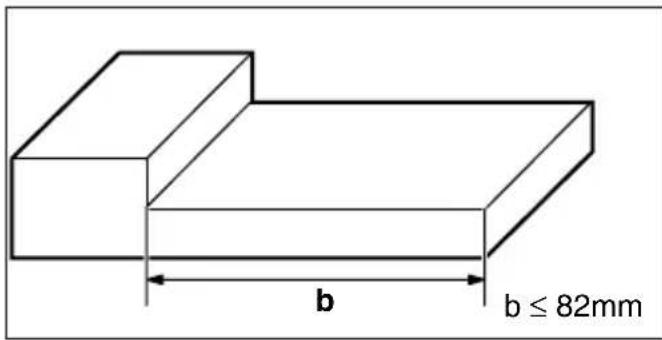
| Maximum planing width | 82 mm |
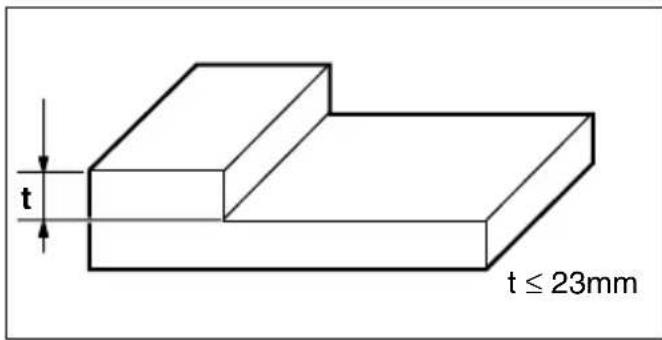
| Maximum planing depth | 3 mm (continuous adjustment) |
| Power supply | Electric, voltage and frequency to be checked according to the mains |
| Sound pressure level | 89 dB(A) |
| Sound power level | 102 dB(A) |
| Vibration acceleration | 3 m/s² |
| Main functions | Planing, rebating, chamfering, beveling |
| Maintenance and cleaning | Blow through the air slots; clean the sole and ejection with alcohol after planing resinous wood |
| Safety | Wear hearing protection recommended; remove the plug before working on the cutter block; keep hands away from the blade during operation |
| Spare parts (references) | Carbide blade: 30 282; Rustic equipment set (2 HSS blades + pressure bars + wrench): 30 565 |
| Repairability | Repairs by a specialist only; Metabo Canada address for service |
Frequently Asked Questions - HO 0882 METABO
User questions about HO 0882 METABO
0 question about this device. Answer the ones you know or ask your own.
Ask a new question about this device
Download the instructions for your Plane in PDF format for free! Find your manual HO 0882 - METABO and take your electronic device back in hand. On this page are published all the documents necessary for the use of your device. HO 0882 by METABO.
USER MANUAL HO 0882 METABO
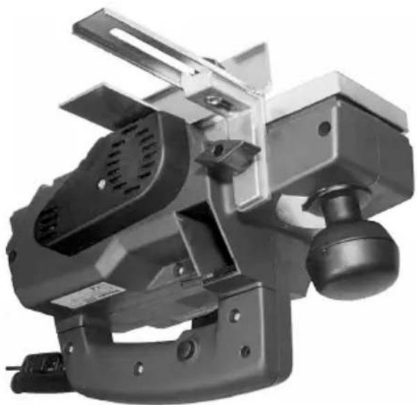
natural_image
Exterior view of a mechanical power tool with handle and mounting bracket (no visible text or symbols)
natural_image
Simple line drawing of an open book with a lowercase 'i' symbol on the right page (no text or labels)F Equipement standard
ES Volumen de suministro
PT Equipamento standard
natural_image
Close-up of hands operating a portable power strip device (no visible text or symbols)natural_image
Close-up of a mechanical component with a black clip and arrow indicator (no readable text or symbols)natural_image
Close-up of a mechanical component with labeled parts (1 and A), no readable text or symbols beyond labels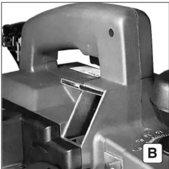
natural_image
Close-up of a mechanical component with no visible text or symbols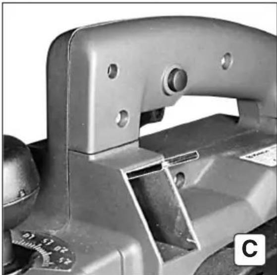
natural_image
Close-up of a mechanical clamp or bracket component with mounting holes and a small scale dial (no visible text or symbols)F Ejection des sciures
natural_image
Close-up of a mechanical component with mounting holes and a scale bar, labeled 'A' in corner (no readable text or symbols)
natural_image
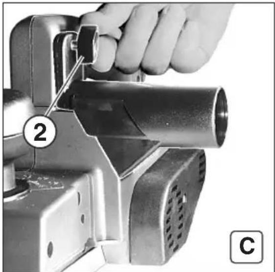
Close-up of a hand using a handheld device to adjust a cylindrical component, labeled with number 2 and letter C (no text or symbols on the device itself)F Extraction des sciures (A-D)
natural_image
Close-up of a hand using a power crimping tool to adjust a component, labeled with number 2 and letter B (no text or symbols on the object itself)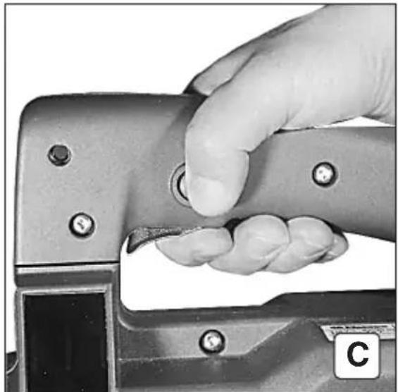
natural_image
Close-up of a hand using a metal tool to press or adjust a button (no visible text or symbols)natural_image
Close-up of a mechanical tool with handle and blade assembly (no visible text or symbols)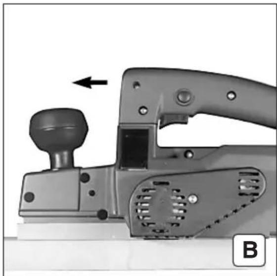
natural_image
Close-up of a mechanical tool with a knob and handle, showing a component with an arrow indicating direction (no text or symbols visible)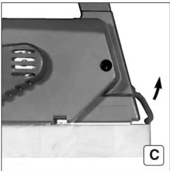
natural_image
Close-up of a mechanical component with a curved arrow indicating direction, no visible text or symbolsF Rabotage de surfaces (A-C)
natural_image
Close-up of a mechanical component with a black arrow pointing to a surface feature, labeled 'B' in the corner (no text or symbols on the main subject)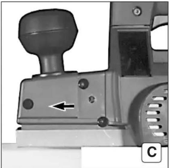
natural_image
Close-up of a mechanical lever mechanism with a knob and directional arrow (no text or symbols visible)F Biseautage
natural_image
Close-up of a mechanical device with labeled components and directional arrows (no readable text or symbols)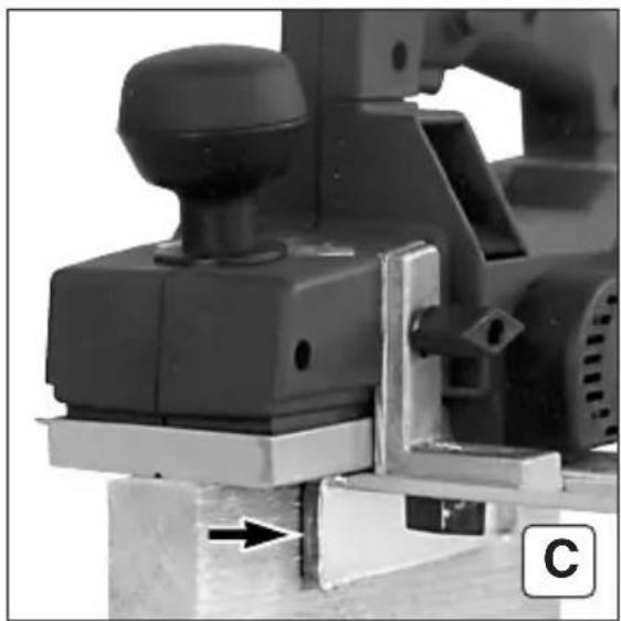
natural_image
Close-up of a mechanical assembly with a knob and lever mechanism (no visible text or symbols)F Chanfrein (A-C)
natural_image
Mechanical component with labeled part '2' and identifier 'B' (no readable text or symbols beyond labels)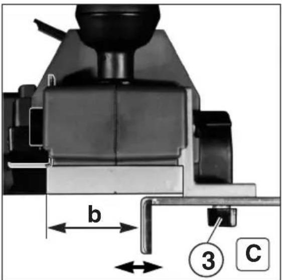
F Feuillure (A-D)
natural_image
Mechanical tool with labeled parts and directional arrow (no readable text or symbols)natural_image
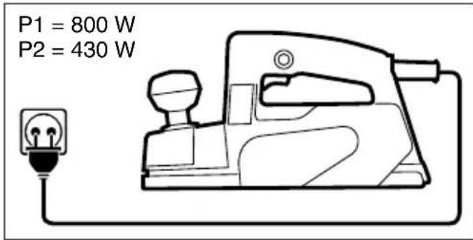
Pure electrical circuit diagram showing a power socket connected to an inductor with arrows indicating direction (no text or symbols)PT Montar e desmontar as lâminas (A-J)
natural_image
Close-up of a hand pressing a small piece on a metal mechanical component (no visible text or symbols)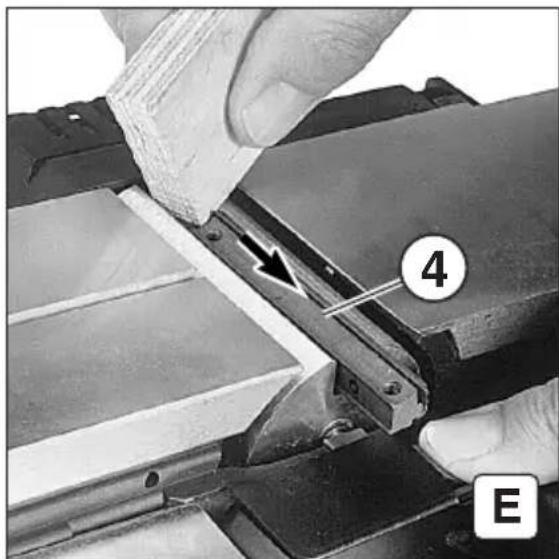
natural_image
Close-up of hands operating a mechanical device with a numbered component (4 and E) and an arrow indicating a process or operation (no readable text or symbols beyond labels)
D: Rabattre la trappe de protection.
natural_image
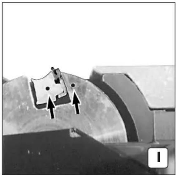
Close-up of a mechanical component with two arrows pointing to features, no visible text or symbols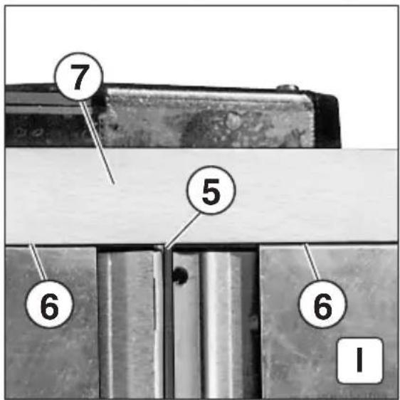
natural_image
Close-up of a hand inserting a metal clip into a metallic frame (no text or symbols visible)natural_image
Pure electrical circuit symbol showing a power socket connected to an inductor with an arrow indicating direction (no text or labels)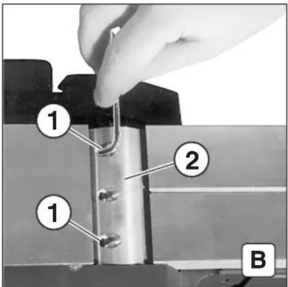
natural_image
Close-up of a hand pressing down on a mechanical component with a white arrow indicating the tool (no text or symbols visible)natural_image
Close-up of hands using a tool to adjust or install a mechanical component, with no visible text or symbols.


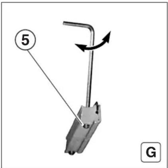
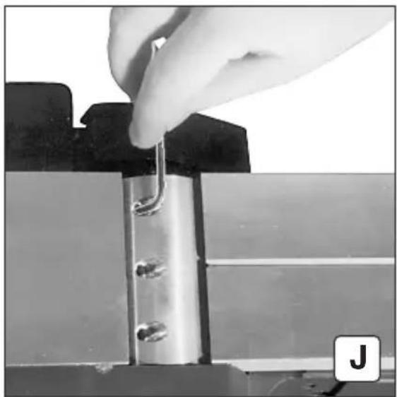
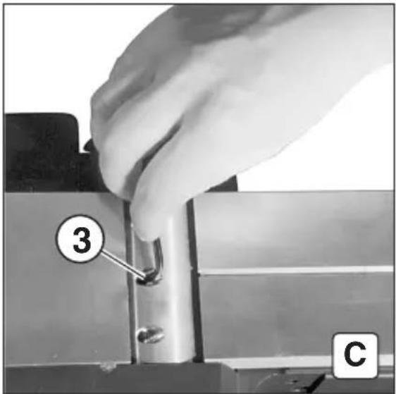
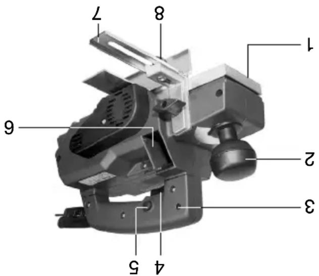
F: Desserrer les vis sans tête (5) avec une clé à fourche (2 mm). G: La hauteur de la lame du rabot est réglée par la rotation des vis sans tête (5).
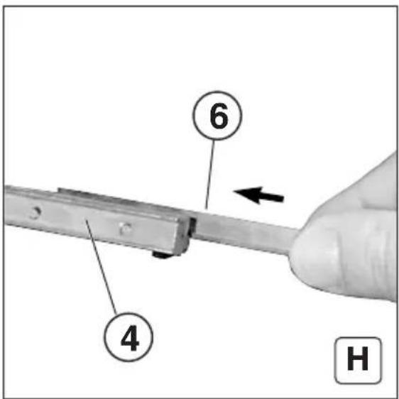
H: Mettre la lame du rabot (6) en place dans la barrette de pression (4).
ES F: Con una llave hexagonal (2 mm), soltar los pasadores roscados (5). G: Girar los pasadores roscados (5) para ajustar la altura de la cuchilla cepilladora.
H: Introducir la cuchilla cepilladora (6) en el listón de apriete (4).
(PT) F: Soltar os parafusos sem cabeça (5) com a chave para parafusos sextavados internos (2 mm).
G: Para regular a altura da lâmina, rodar os parafusos sem cabeça (5).
H: Introduzir a lâmina (6) na régua de pressão (4).
natural_image
Close-up of a mechanical component with two arrows pointing to a small object, no visible text or symbolsnatural_image
Close-up of a hand holding a metal tool inserted into a mechanical component (no visible text or symbols)natural_image
Close-up of a mechanical component with a white arrow pointing to a grating or ventilation grille (no text or symbols visible)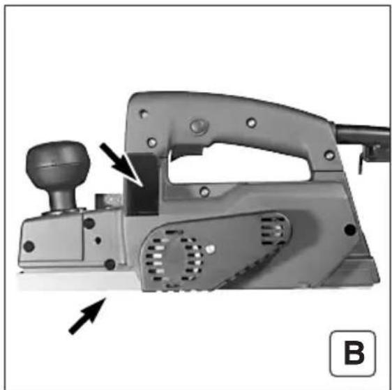
natural_image
Mechanical tool with lever and adjustment knob, no visible text or symbolsF Nettoyage
natural_image
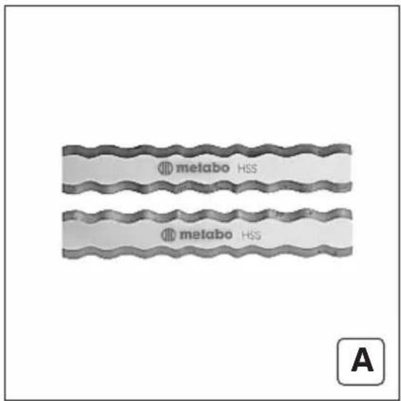
Two parallel horizontal lines with a label 'A' in the corner (no other text or symbols)
natural_image
Metal mechanical component with a bracket and mounting bracket, labeled 'B' in the corner (no text or symbols on the component itself)
natural_image
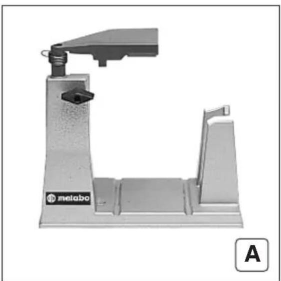
Mechanical device with a lever and base plate, labeled 'melabo' and marked with letter 'A' (no other text or symbols visible)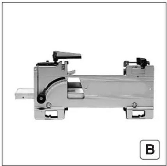
natural_image
Mechanical assembly component with mounting brackets and a curved internal structure (no visible text or symbols)West Chester, PA 19380
Tel: 800-638-2264
Fax: 800-638-2261
e-mail: info@metabousa.com


Tel. : (905) 755-0608 Fax : (905) 755-0611 Tel. : (toil free) 1 877 metabot (1 877 638-2261) Fax : (toil free) 1 877 metabog (1 877 638-2269)
In Canada : Metabo Canada Inc. 190 Britannia Road East Mississauga, ON L4Z 1W6
1231 Wilson Drive Metabo Corporation Tel: 800-638-2264 Fax: 800-638-2264 West Chester, PA 19380 e-mail: info@metabousa.com
WARNING Metabo reserves the right to reject under the warranty program any tool repaired or altered by the user or an unauthorized service station.
After approximately 300 working hours, your Planer should be thoroughly cleaned and inspected. This work should be done only by skilled personnel, i.e. an Authorized Metodo Corporation Service Center. Metodo Corporation reserves the right to reject under the warranty program, any tool repaired or removed- held by the user or unauthorized service stations. When servicing, use only identical replacement parts.
Servicing
ing, brush replacement, inspection and preventive maintenance if necessary.
The Planer has auto-stop carbon brushes. When the brushes are worn down, the automatic tripping device of the brushes breaks the circuit and the motor stops running. At this time, we recommend bringing the tool to one of our Service Stations for clean-
Carbon Bushes
To prevent dust from settling inside tool, the motor should be cleaned occasionally by using compressed air blown into the tool through the air vent slots in the motor housing.
Warning: Before performing any maintenance work, disconnect tool from power source.
Your planer must be given proper maintenance in order to ensure effi- client performance and long time. In general, all maintenance should be performed by an Authorized Metabo Service Center.
Mainenance
Resin buildup on the work surface of the planer shoe can be removed with mineral spirits or other similar clean- ing aigent. Do not use acids or metal scrapers which could damage the shoe by causing scratches which might scratch the surface of material to be plained.
Cleaning Planer Shoe
To make the rabbet, rest the depth stop on top of the work surface to be rabbeted with the planer flush against the work surface. Turn the planer on and push it across the work surface at a smooth and steady speed.
The depth stop (1 t) is to be used for setting the depth of the rabbit from 0" to 7/8" deep. By loosening the thumbscrew, move the stop to the desired depth then tighten it.
distance. Then follow the steps for installing the blades and pressure bars in the cutter head.
For rabbeting, the width of cut can be adjusted by following the steps for removing the blades: pushing the blades out of the pressure bars to the desired width of cut (1/8" maxi- mumm). Make sure both blades extend from the pressure bar the exact same
Rabbeting
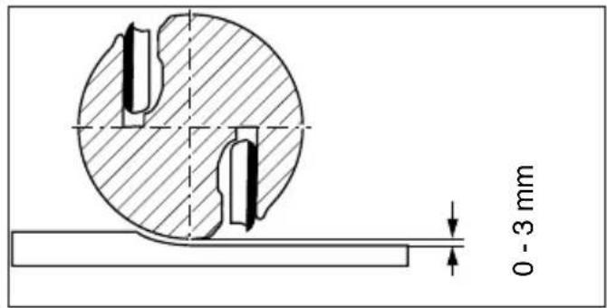
The spacer rest (9) makes it possible for the planer to be put down without one of the cutter blades touching the surface on which the tool is resting. Do not slide the planer forward on the surface when it is put down on the rest.
Once you have finished the planing work, switch off the motor.
The carbide cutter blades permelt use of the planer for dressing the edges of chipboard and blockboard and for plaining end grain.
Be sure to move the edge guide across the shoe to expose only that portion of the blade needed for the planing operation.
Use the planing guide (7) for trim- ming the edges of boards and for similar jobs. The guide can be set to the desired distance from the edge of the work after loosening the thumb- screw (8).
The vee-groove (1) in the front part of chamfering.
The best finish is obtained by moving the planer forwards slowly and evenly. This is also the best way of treating the cutter blades and prevents accidents from occurring. To take off the final shaving, the planer should be set to a small depth of cut. When planning plastics, the planing depth must not be more than 1/16 inch.
When the planer is slid forward on the surface to be placed, the spacer rest (9) is automatically pushed back it strikes the edge of the work.
with the work.
Make sure that the cutter blades are free to rotate (otherwise there is a danger of the planer kicking back). The cutter head guard (12) moves automatically upwards on contact.
Switch on the motor before you bring the planer up to the workpiece.
Arrange the power cord to the planer so that it will not get in the way while you are planning and so that it cannot, under any circumstances, touch the cutter head while it is spinning.
Planning operation
vice versa.
By rocking the flap in the chip outlet (6) it is possible to change the direct- tion in which shavings and chips are elected. Looking in the direction in which the planer moves, press down the left-hand side of the flap for the chips to be elected to the right (and
Chip election
The pressure bars are factory adjusted for the cutter blade height. No fur- ther adjustment of height should be necessary. However, two adjusting sears are provided in the pressure bars for blade height adjusting if the need should arise.
key.
After properly positioning the pries sure bars in the cutter head with the planer blades in the pressure bars, tighen the three clamping screws in the cutter head by means of the Allen
Clean the blades and the grooves in the pressure bars before putting the blades back in the pressure bars to insure proper fit. Important: When installing the press- sure bars with blades into the cutter head, make sure the blades are resulting in the groove on the side furtherst from the clamping screws. Also, the pressure bar faces must be flush with the face of the cutter head. Incorrect installation could be damag- ing to the planer and dangerous to the operator.
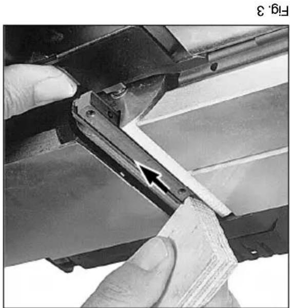
Press down the retractable guard on the side of the machine and slide out the pressure bar and blade (fig. 3).
Fig.2
natural_image
Close-up of a hand inserting a metal spring into a mechanical bracket (no text or symbols visible)Fig.4
natural_image
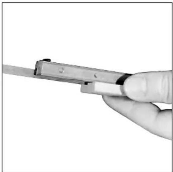
Close-up of a hand holding a metal tool, no visible text or symbolsAfterwards, the planer blade can be pushed out of the pressure bar with a piece of wood (fig. 4).
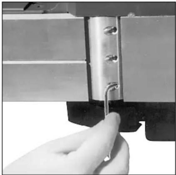
To remove the planer blades, loosen the clamping screws in the cutter head using the Allen key supplied. It is not necessary to remove the clamping screws. Loosen the outer clamping screws. Revolution and the center clamping screw three revolutions (fig. 2).
possible.
Dull blades not only make the planer work harder and do a less present- able job, but also can cause the planer to kick back at the operator. Therefore, it is essential that dull blades be replaced as quickly as
The Ho 0882 is equipped with rever- slide carbidie blades which are not designed to be resharpened. When the cutting edges become dull, the second cutting edges can be used. The blades must be replaced when both cutting edges become dull.
The planer is equipped with cardboard blades. This permits use of the tool for planing cross-cut wood and both plain and laminated chipboard.
natural_image
Close-up of hands using a tool to cut or adjust a metal bracket, with an arrow pointing to a detail (no text or symbols visible)Inspect all work material to be plined before beginning work. Especially in the case of used wood, nails or other foreign material may be imbedded in the wood which could damage the planer blades. Be sure to remove any such foreign material before attempting to plane workpiece.
Preparation of material
By continuing to turn the knob beyond the markings on the scale, it is possible to set for an even greater depth of cut up to 1/8". However, at this depth, there is a risk of the planer being overloaded (e.g., when planning hard wood), and because of this, these settings should only be used for narrow workpieces (up to approxi-mately 1 ^5/8" wide).
Planning depths from 0" to 5/64" can be set easily by turning the knob (2). To set the depth of cut, begin with the pointer on the knob resting on the zero mark on the scale. Rotate knob clockwise to a point just beyond the desired setting, then turn knob back to the desired setting.
Setting the planing depth
before servicing, setting-up, or con- venting.
For continuous operation, the trigger can be locked in the »on« position by pressing the locking button (5) after depressing the trigger. Depends the triggering again to release the trigger. Warning: Make sure that the tool is disconnected from the power supply
Fig.1
The motor is turned on by pressing the trigger (4). Relaising the trigger switches the tool off.
Switch
One set No. 30 282 Carbide Planer Blades and Allen Key.
Standard Equipment
This Planer complies with applicable OSHA Standards.
Net weight 9 lbs.
Rated 115 V 60 c/s 6.5 amps.
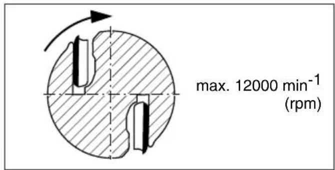
RPM 12,000
Max. rabbeting depth 7/8"
Max. depth of cut 1/8" (3 mm)
Max. width of cut 3
Specifications

Model: Ho 0882
Planer
Metabo

Gage sizes in shaded areas are normally not available as flexible extension cords.
| Ampere Rating Range | Volts Length of Cord in Feet | |||||||||
| 120 V 25 | 5 Ft 50 | 1 Ft 100 Ft | 150 Ft | 200 Ft | 250 Ft | 300 Ft | 400 Ft | 500 Ft | 600 Ft | |
| 230 V 50 | 0 Ft 100 | Ft 200 | Ft 300 | Ft 400 | Ft 500 | Ft 600 | Ft 800 | Ft 1000 Ft | ||
| 2 - 3 | 1 | 8 | 1 | 8 | 1 | 6 | 1 | 4 | 1 | |
| 3 - 4 | 1 | 8 | 1 | 8 | 1 | 6 | 1 | 6 | 1 | |
| 4 - 5 | 18 | 18 | 14 | 12 | 12 | 10 | 10 | 8 | 8 | |
| 5 - 6 | 18 | 16 | 14 | 12 | 10 | 10 | 8 | 8 | 6 | |
| 6 - 8 | 18 | 16 | 12 | 10 | 10 | 8 | 6 | 6 | 4 | |
| 8 - 10 | 18 | 14 | 12 | 10 | 8 | 8 | 6 | 6 | 2 | |
| 10 - 12 | 16 | 14 | 10 | 8 | 8 | 6 | 4 | 4 | 2 | |
| 12 - 14 | 16 | 12 | 10 | 8 | 6 | 6 | 4 | 2 | 2 | |
| 14 - 16 | 16 | 12 | 10 | 8 | 6 | 6 | 4 | 2 | ||
| 16 - 18 | 14 | 12 | 8 | 8 | 6 | 4 | 4 | 2 | ||
| 18 - 20 | 14 | 12 | 8 | 6 | 6 | 4 | 4 | 2 | ||
Use an extension cord heavy enough to carry the current your tool will draw. An undersized cord will cause a serious drop in voltage, resulting in loss of power and possible motor damage from overheating. The following table shows the correct size to
Extension cords
Your Metodo Planer has the double insulation system. Wherever there is electric current in the tool, the user is protected against electrical shock by two separate sets of insulation. The double insulation system offers pro-techion equal to properly grounded tools without the need of a grounding connector. The tool is equipped with a two-wire cord and a two-prong plug which can be used on standard 120 volt outlets. No grounding of the tool is necessary. Important: Servicing a double insu-lated tool requires much care and knowledge, and should only be per-nician. For service return the tool to nearest you or directly to Metodo Corporation. Use only original factory
Double insulation
Save these instructions
use depending on cord length and naempilate ampereage rating. If in doubt, use the next heavier gage. NOTE: The smaller the gage number, the heavier the cord. Repair or replace damaged cords. For purchase of extension cords, see your distributor.
motor.
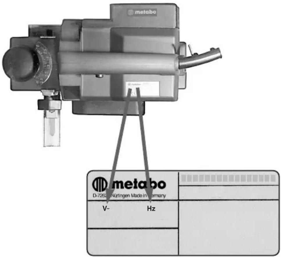
Before connecting the tool to a power source (recertacle, outlet, etc.) be sure that specificed on the nameplate of the voltage supplied is the same as that specificed on the nameplate of the voltage supplied is the same as her than that specificed for the tool can result in serious injury to the user as well as damage to the tool. If in doubt, do not plug in the tool. Using a power source with a voltage lower than the nameplate rating is harmful to the
Voltage warning
State These Instructions
When servicing use only identical replacement parts.
Replacement Parts
Do not use tool if switch does not turn it on and off.
Have defective switches replaced by authorized service center.
ized service center unless other-wise indicated elsewhere in this instruction manual.
A guard or other part that is damaged should be properly repaired or replaced by an author-
Check for alignment of moving parts, binding of moving parts, breakage of parts, mounting, and any other condition that may affect its operation.
Before further use of the tool, a guard or other part that is damaged should be carefully checked to determine that it will operate property and perform its intended function.
Check Damaged Parts
Watch what you are doing. Use common sense. Do not operate tool when you are tired.
Stay Alert
When the tool is used outdoors, use only extension cords intended for use outdoors and so marked.
Outdoor Use Extension Corks
Don't carry plugged-in tool with finger on switch. Be sure switch is off when plugging in.
Avoid Unitennial Starting
it on. Form habit of checking to see that keys and adjusting wrenches are removed from tool before turning
Remove Adjusting Keys and Wrenches
When not in use, before servicing, and when changing accessories, such as blades, bits, cutters.
Discount Tools
Inspect extension cords period- locally and replace if damaged. Keep handles dry, clean, and free from oil and grease.
Inspect tool cords periodically and if damaged, have repaired by authorized service facility.
Keep tools share and clean for better and safer performance. Follow instructions for lubricating and changing accessories.
Maintain Tools With Care
at all times.
Keep proper footing and balance
Don't Overreach
Never clamp the tool in a wise. You can damage the motor.
tool.
and it frees both hands to operate
It's safer than using your hand
Use claims or a wise to hold work.
Secure Work
sharp edges.
Keep cord from heat, oil, and
to disconnect from receptacle.
Never carry tool by cord or yank it
Don't Abuse Cord
ting operation is dusty.
Also use face or dust mask if cut-
Use Safety Glasses
contain long hair.
Wear protective hair covering to
working outdoors.
footwear are recommended when
Rubber gloves and non-skid
moving parts.
Jewelry. They can be caught in
Do not wear loose clothing or
Dress Property
or logs.
intended – for example – don't use circular saw for cutting tree limbs
Don't use tool for purpose not
tool.
ment to do the job of a heavy-duty
Don't force small tool or attach-
Use Right Tool
It will do the job better and safer at the rate for which it was intended.
Don't Force Tool
up place – out of reach of children.
stored in dry, and high or locked-
When not in use, tools should be
Store Idle Tools
from work area.
All visitors should be kept away
extension cord.
Do not let visitors contact tool or
Keep Children Away
hazard. Use stick on labels.
insulation and can create a shock
It compromises the double
Never attach metal tags to the tool.
for enclosures.
pipes, radiators, ranges, refrigera-
grounded surfaces. For example:
Prevent body contact with
Guard Against Electric Shock
flammable liquids or gases.
Do not use tool in presence of
Keep work area well lit.
wet locations.
Don't use power tools in damp or
Don't expose power tools to rain.
Consider Work Area Environment
invite injuries.
Cluttered areas and benches
Keep Work Area Clean
Read All instructions
Injury, including the following:
of fire, electric shock, and personal
always be followed to reduce the risk
basic safety precautions should
WARNING: When using electric tools,
Rules
General Power Tool Safety
of the tool.
safety rules and understand all instructions in this manual for state operation
Before connecting your tool to a power source be sure you have read all
ENG Instructions for Use
natural_image
Mechanical device with clamping mechanism and mounting bracket (no visible text or symbols)No 0882


- F Ejection des sciures
- F Extraction des sciures (A-D)
- F Rabotage de surfaces (A-C)
- F Biseautage
- F Chanfrein (A-C)
- F Feuillure (A-D)
- F Nettoyage
- Servicing
- Carbon Bushes
- Mainenance
- Cleaning Planer Shoe
- Rabbeting
- Planning operation
- Chip election
- Preparation of material
- Setting the planing depth
- Extension cords
- Double insulation
- Save these instructions
- Voltage warning
- State These Instructions
- Replacement Parts
- Check Damaged Parts
- Stay Alert
- Outdoor Use Extension Corks
- Avoid Unitennial Starting
- Remove Adjusting Keys and Wrenches
- Discount Tools
- Maintain Tools With Care
- Don't Overreach
- Secure Work
- Don't Abuse Cord
- Use Safety Glasses
- Dress Property
- Use Right Tool
- Don't Force Tool
- Store Idle Tools
- Keep Children Away
- Guard Against Electric Shock
- Consider Work Area Environment
- Keep Work Area Clean
- Read All instructions
- Rules
- General Power Tool Safety
Brand : METABO
Model : HO 0882
Category : Plane