
DH 330 - Plane METABO - Free user manual and instructions
Find the device manual for free DH 330 METABO in PDF.
| Brand | Metabo |
| Model | DH 330 |
| Product type | Wood planer (jointer-planer) |
| Power supply | 230 V ~ 50 Hz (or 110 V ~ 50 Hz) |
| Motor power | 1800 W (230 V) / 1620 W (110 V) |
| No-load speed (cutterhead) | 9800 min⁻¹ (230 V) / 9100 min⁻¹ (110 V) |
| Feed speed | 7.5 m/min |
| Maximum depth of cut | 3 mm |
| Maximum planing width | 330 mm |
| Maximum workpiece height | 152 mm |
| Minimum workpiece height | 5 mm |
| Minimum workpiece length | 356 mm |
| Dimensions (folded) - Depth | 350 mm |
| Dimensions (folded) - Width | 585 mm |
| Dimensions (folded) - Height | 495 mm |
| Dimensions (planing table) - Depth | 600 mm |
| Dimensions (planing table) - Width | 370 mm |
| Weight | 35 kg |
| Protection class | II |
| Protection rating | IP 20 |
| Sound pressure level LpA | 88 dB(A) |
| Sound power level LWA | 101 dB(A) |
| Safety | Cutterhead guard, on/off switch, thermal protection, undervoltage relay, reset button |
| Maintenance | Regular chip cleaning, lubrication of guide bars, replacement of planer blades and carbon brushes |
| Included accessories | Push stick, dust extraction adapter, hex key, blade changing tool, two stop pins |
| Repairability | Spare parts available: planer blades, carbon brushes, drive belt; repair by a professional electrician |
Frequently Asked Questions - DH 330 METABO
User questions about DH 330 METABO
0 question about this device. Answer the ones you know or ask your own.
Ask a new question about this device
Download the instructions for your Plane in PDF format for free! Find your manual DH 330 - METABO and take your electronic device back in hand. On this page are published all the documents necessary for the use of your device. DH 330 by METABO.
USER MANUAL DH 330 METABO
We herewith declare in our sole responsibility that this product complies with the following standards in accordance with the regulations of the undermentioned Directives testreport *** issuing test office ***
*** Dekra Testing and Certification GmbH, Enderstraße 92b, 01277 Dresden, Germany; Notified Body No. 2140
Bernd Fleischmann
Director Innovation, Research and Development
Dokumentationsbevollmachtigter/ responsible person for documentation/ Chargé de la documentation
Metabowerke GmbH
Metabo-Allee 1
D-72622Nurtingen

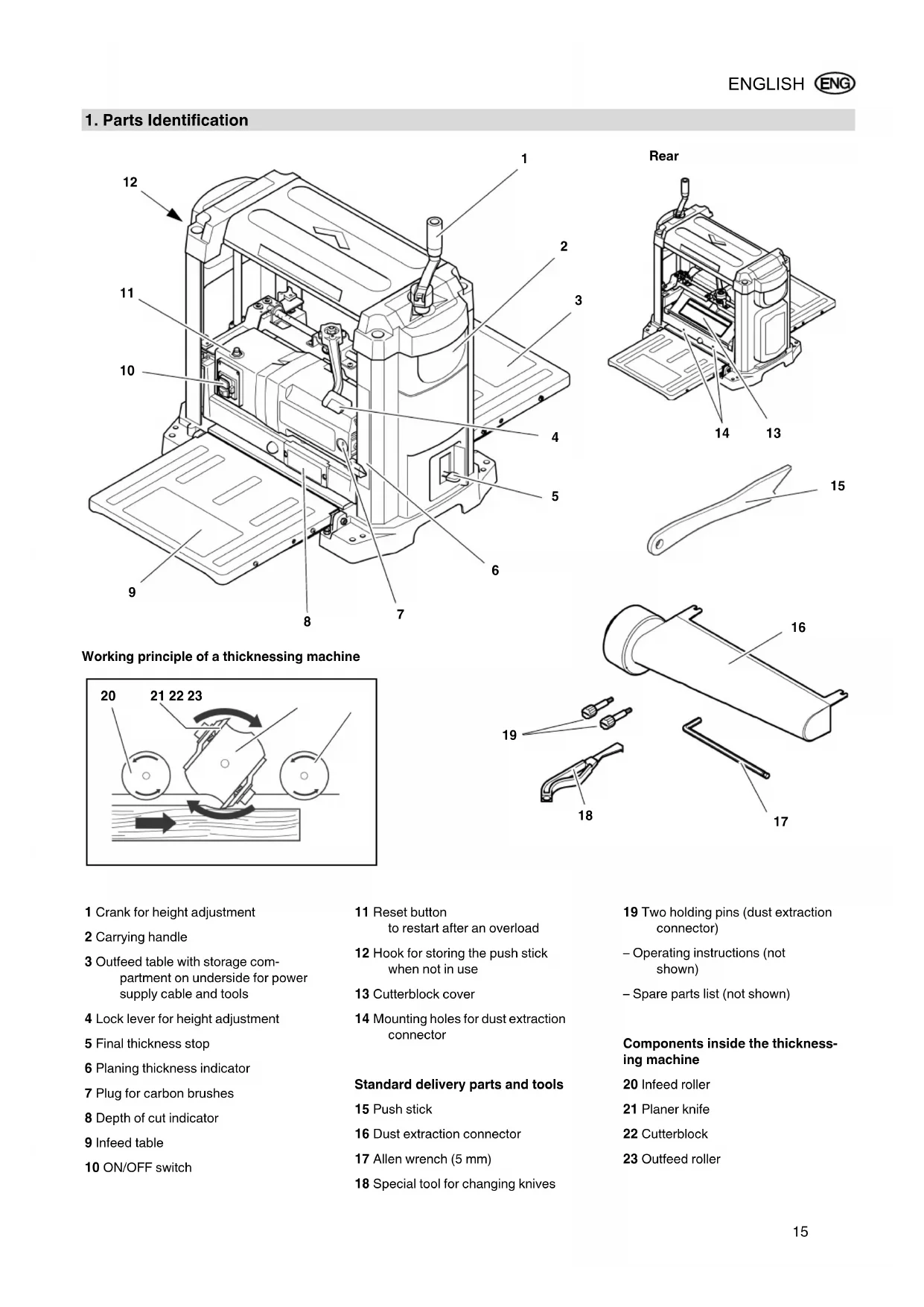
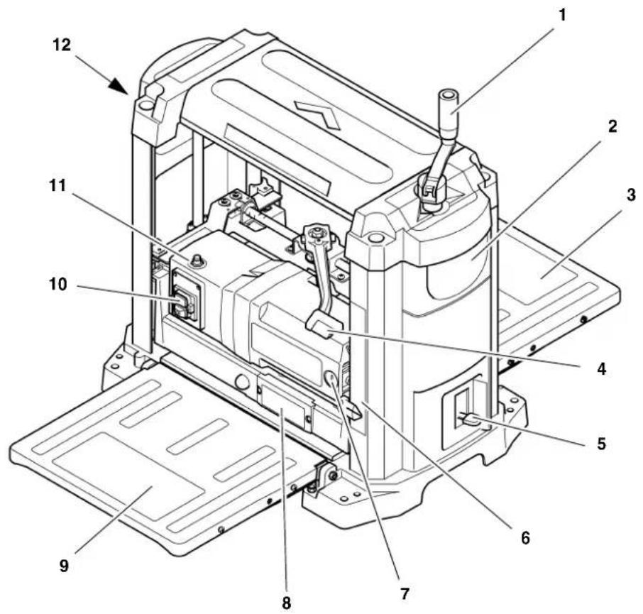
1. Parts Identification
Working principle of a thicknessing machine
1 Crank for height adjustment
2 Carrying handle
3 Outfeed table with storage compartment on underside for power supply cable and tools
4 Lock lever for height adjustment
5 Final thickness stop
6 Planing thickness indicator
7 Plug for carbon brushes
8 Depth of cut indicator
9 Infeed table
10 ON/OFF switch
11 Reset button to restart after an overload
12 Hook for storing the push stick when not in use
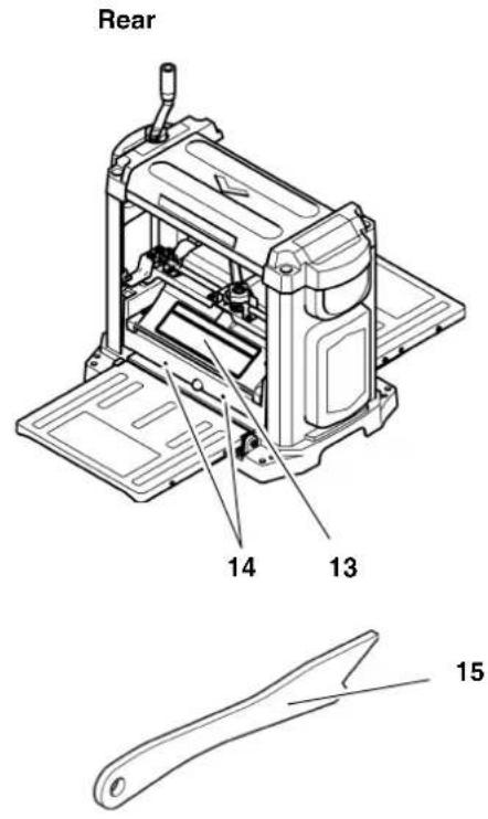
13 Cutterblock cover
14 Mounting holes for dust extraction connector
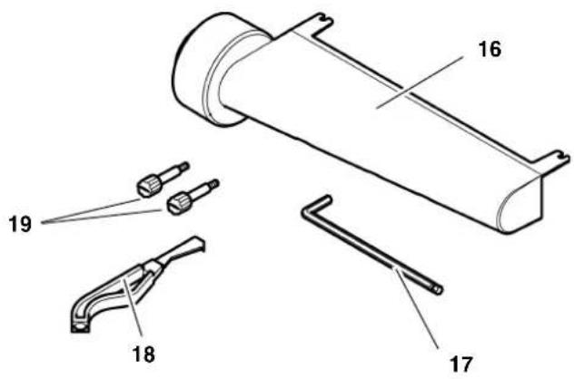
Standard delivery parts and tools
15 Push stick
16 Dust extraction connector
17 Allen wrench (5 mm)
18 Special tool for changing knives
19 Two holding pins (dust extraction connector)
-Operating instructions (not shown)
- Spare parts list (not shown)
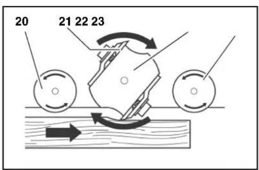
Components inside the thicknessing machine
20 Infeed roller
21 Planer knife
22 Cutterblock
23 Outfeed roller
Table of Contents
- Parts Identification 15
- Please Read First! 16
- Safety 16
3.1 Specified Conditions of Use 16
3.2 General Safety Instructions 16
3.3 Symbols on the Machine 18
3.4 Safety Devices 18 - Special Product Features.... 18
- Operating Controls 18
- Initial Operation 19
6.1 Machine Installation 19
6.2 Aligning the Infeed and Outfeed Tables. 19
6.3 Dust Collector 20
6.4 Mains Connection.. 20 - Operation 20
7.1 Planing Work Pieces 21 - Care and Maintenance 21
8.1 Machine Cleaning and Lubrication. 22
8.2 Changing the Planer Knives 22
8.3 Adjusting the Final Thickness Stop. 23
8.4 Checking and Replacing the Carbon Brushes. 24
8.5 Storage 24
8.6 Transport 24 - Troubleshooting 24
- Available Accessories 25
- Repairs 25
- Technical Specifications 26
2. Please Read First!
These instructions have been written to make it easier for you, the operator, to learn how to operate the machine and to do so safely. These instruction should be used as follows:
- Read these instructions before use. Pay special attention to and always follow all safety instructions.
These operating instructions are intended for people with basic technical knowledge regarding the operation of a machine like the machine described herein. Inexperienced persons are strongly advised to seek competent advice and guidance from an experienced person before operating this machine. - Keep all documents supplied with this machine for future reference. Retain proof of purchase in case of warranty claims.
If you lend or sell this machine be sure to have these instructions go with it.
The manufacturer is not liable for any damage resulting from neglect of these operating instructions.
Information in these instructions is denoted as under:

Danger! Risk of personal injury or environmental damage.
Risk of electric shock! Risk of personal injury by electric shock.

Drawing-in/trapping hazard! Risk of personal injury by body parts or clothing being caught.

Caution! Risk of material damage.

Note: Additional information.
- At times numbers are used in illustrations (1, 2, 3, ...). These numbers
indicate component parts;
are consecutively numbered;
- correspond to the number(s) in brackets (1), (2), (3) ... in the neighbouring text.
Numbered steps must be carried out in sequence.
- Instructions which can be carried out in any order are indicated by a bullet () .
Lists are indicated by a dash (-)
3. Safety
3.1 Specified Conditions of Use
Use this machine only for thickness planing of solid wood. Any other use is not as specified.
The following tasks may not be carried out with this tool:
- Insertion work (i.e. any work that does not extend the full length of the workpiece),
- Planing of cavities, pins or cut-outs,
- Planing of heavily curved wood with which there is insufficient contact with the holding and intermediate table.
The permissible work piece dimensions must be observed (see "Technical Specifications").
Any other use is not as specified. Use not as specified, modification of the machine
or use of parts not tested and approved by the manufacturer can cause unforeseen damage.
3.2 General Safety Instructions
A thickening machine is a dangerous tool which can, due to operator carelessness, cause severe injury.

Caution!
When using power tools, the following basic safety measures must be taken to protect against electric shock, other injury or fire.
- When using this machine follow the following safety instructions, to exclude the risk of personal injury or material damage.
- Please also follow the special safety instructions in the respective chapters.
- Where applicable, follow the legal directives or regulations for the prevention of accidents pertaining to the use of thickening machines.

General hazards!
- Keep your work area tidy - a messy work area invites accidents.
- Be alert. Know what you are doing. Set out to work with reason. Do not operate the machine when you are lacking concentration.
- Do not operate the machine while under the influence of alcohol, drugs or medication.
- Consider environmental conditions. Keep work area well lighted.
- Prevent adverse body positions. Ensure firm footing and keep your balance at all times.
- Use suitable workpiece supports to support the workpiece when cutting long stock. Set the workpiece rests to an appropriate height.
- Do not operate the machine near inflammable liquids or gases.
- This thickening machine shall only be started and operated by persons familiar with thickening machines and the dangers associated with the operation of thickening machines. Persons under 18 years of age shall use this machine only in the course of their vocational training, under the supervision of an instructor.
- Keep bystanders, particularly children, out of the danger zone. Do not permit other persons to touch the machine or power cable while it is running.
- Do not overload the machine—use it only within the performance range it
was designed for (see "Technical specifications").
- Never set the depth of cut to more than 1/8'' (3 mm).
- Turn power off if the machine is not used.

Danger! Risk of electric shock!
- Do not expose the machine to rain.
Do not operate the machine in damp or wet environment. - Prevent body contact with earthed objects such as radiators, pipes, cooking stoves, refrigerators when operating this machine.
- Do not use the power cable for any purpose it is not intended for.
- Regularly check extension cables and replace if damaged.
- When working out of doors, only use extension cables that are also approved for outdoors.
- Ensure the tool is disconnected from power before servicing.
- Ensure the machine is disconnected from power before servicing.

Cutting hazard when touching
the rotating cutterblock!
Always keep your hands well clear of the cutterblock.
Use suitable feeding aids, if necessary.
- Keep sufficient distance to driven components when operating the electric machine.
- When in operation, do not reach into the dust collector or the cutterblock cover.
- To prevent accidental starting, always turn the machine OFF:
after a power failure,
before unplugging or plugging in.
- Do not operate the machine without all guards installed.
- Wait until the cutterblock has come to a complete stop, before removing jammed parts or small cutoffs, chips, etc. from the work area.

Cutting hazard, even with the block at standstill!
- Wear gloves when changing planer knives.
- Store the planer knives in a safe place and in such a manner that nobody can get hurt.

Drawing-in/trapping hazard!
During thickening the work piece is automatically drawn into and transported through the thickening machine.
- Always make sure that no body parts or objects can be drawn into the machine together with the work piece. Do not wear neckties and also no gloves and no garments having wide sleeves. Contain long hair with a hairnet.
- Never attempt to thickness any work pieces which contain
- ropes,
strings,
-cords, - cables or
- wires, or work pieces to which any of the above are attached.

Risk of injury by work piece back (work piece is caught by the cutting cutterblock and thrown back to the operator)!
- Always use sharp planer knives. Blunt planer knives may get caught in the surface of the work piece.
- Do not jam work pieces.
- Do not work work pieces which are shorter than 14 inch (356 mm).
- If in doubt, check work piece for inclusion of objects (e.g. nails or screws).
- Never thickness several work pieces at the same time. Risk of personal injury if individual pieces are uncontrolled caught by the cutterblock.
- Remove small cutoffs, scrap, etc. from the work area - when doing so, the cutterblock must be at standstill and the power cable unplugged.
- Ensure that when turning ON (e.g. after servicing) no tools or loose parts are left on or in the machine.

Hazard generated by insuffi- personal protection gear!
- Wear hearing protection.
- Wear safety glasses.
- Wear dust mask.
- Wear suitable work clothes.
- When working outdoors wearing of non-slip shoes is recommended.

Risk of injury by inhaled wood
- Some types of wood dust (e.g. beech, oak, ash) may cause cancer when inhaled. Whenever possible, use a dust collector attached to the thickening machine. The dust col
lector has to comply with the specifications contained in "Technical Specifications".
- When working, minimize the amount of wood dust escaping from the machine into the environs:
remove wood dust deposits in the work area (do not blow away!);
fix any leakages on the dust collector;
- ensure good ventilation.

Hazard generated by modifica- of the machine, or use of parts- sted and approved by the manu- rer!
- Assemble machine in strict accordance with these instructions.
-
Use only parts tested and approved by the manufacturer. This applies especially to all safety devices (see spare parts list for stock numbers).
-
Do not change any parts.

Hazard generated by machine
defects!
- Keep machine and accessories in good repair. Observe the maintenance instructions.
- Before any use check the machine for possible damage: before operating the machine all safety devices, protective guards or slightly damaged parts need to be checked for proper function as specified. Check to see that all moving parts work properly and do not jam. All parts must be correctly installed and meet all conditions necessary for the proper operation of the machine.
- Never use the machine when the power supply cable is damaged. Risk of personal injury by electric shock. Have a damaged power supply cable replaced by a qualified electrician immediately.
- Damaged protection devices or parts must be repaired or replaced by a qualified specialist. Have damaged switches replaced by a service centre. Do not operate the machine if the switch cannot be turned ON or OFF.

Danger from blocking work- s or workpiece parts!
If blockage occurs:
- Switch machine OFF.
- Unplug mains cable.
- Wear gloves.
- Clear the blockage using a suitable tool.
3.3 Symbols on the Machine

Danger!
Disregard of the following warning could lead to severe personal injury or material damage.

Read instructions.

Always keep your hands well clear of the cutterblock. Keep sufficient distance to driven components when operating the electric machine.

Wear safety goggles and hearing protection.

Do not operate the machine in damp or wet environment.
Information on the nameplate:
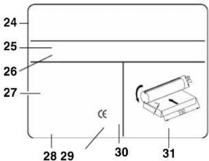
24 Manufacturer
25 Serial number
26 Machine designation
27 Motor specifications (see also "Technical specifications")
28 Date of manufacture
29 CE-mark - indicates that this machine conforms to the EC directive(s) stated in the Declaration of Conformity
30 Waste disposal symbol - the machine can be disposed of through the manufacturer
31 Dimensions of approved planer knives
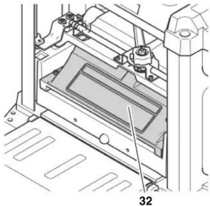
3.4 Safety Devices
Cutterblock cover
The cutterblock cover (32) prevents that the rotating cutterblock can be touched from the top.
The cutterblock cover must be in place, until the cutterblock has come to a complete stop and the power cable is unplugged.
4. Special Product Features
- Up-to-date technology, designed for continuous duty and accurate planning results.
- Robust construction, with handles on housing for complete mobility.
- Infeed and outfeed table for simple and safe handling of long work pieces.
5. Operating Controls
ON/OFF switch
To start = press green switch button (33).
To stop = press red switch button (34).

i Note:
In case of an overload a thermal circuit breaker will trip. The machine can be started again after a few seconds. To restart, first press the reset button (35), then the Start button (33).
An undervoltage relay trips in the event of a voltage failure to prevent restarting of the machine when the power is restored. To restart, press the Start button.
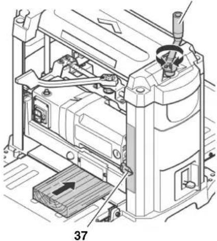
Height adjustment
With the height adjustment the planing thickness (= work piece thickness after planing) is set.
- Per pass a maximum of 3mm material can be removed.
Work pieces of max. 152mm thickness can be planed.
The height adjustment is made by means of a crank (36). Each full turn of the crank raises or lowers the cutterblock head by 1/12" (2 mm).
36
The set planing thickness is indicated on the scale by the pointer (37).
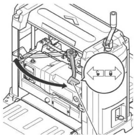
Lock lever for height adjustment
To lock the height adjustment:
- Set lock lever (38) fully to the right, to the position marked
To unlock the height adjustment: - Set lock lever (38) fully to the left, to the position marked G
By means of the height adjustment the planing thickness can be reset.
38
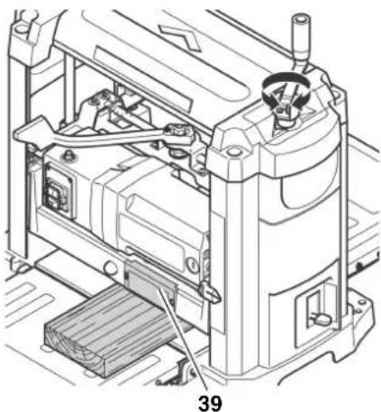
Depth of cut indicator
The indicator (39) indicates the depth of cut, i.e. the amount of material to be removed from the work piece.
The depth of cut can be set from 1 mm to 3 mm.
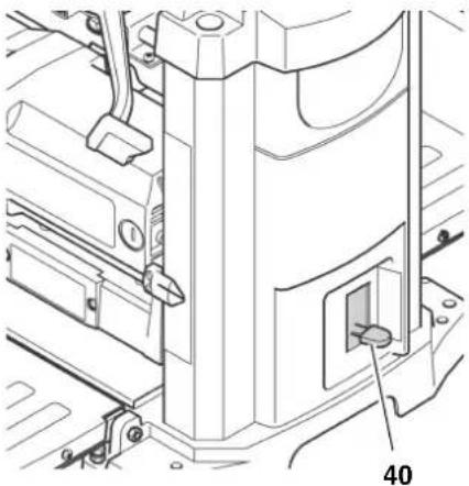
Final thickness stop
With the thickness stop (40) standard planing thicknesses of 1/4'' (6 mm) to 13/4'' (44 mm) can be preset.
Using this feature, work pieces are planed to a uniform thickness without the need for constant measuring.
6. Initial Operation
6.1 Machine Installation
To keep the machine from "wandering" caused by vibrations or to prevent tipping over, the machine must be bolted to a work bench, work stand or similar firm support.

When installing the machine stationary, keep in mind that there must be sufficient space in front and behind the machine to work long work pieces.
- Drill holes into supporting surface, where necessary.
- Put bolts (41) through from the top und secure from below with nuts.
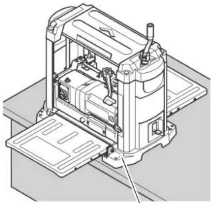
41
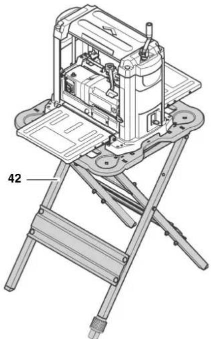
When the machine is to be used mobile:
- Bolt machine to the work stand (42) (see "Available Accessories").
Alternative installation:
- Fasten thicknessing machine to a sheet of 3/4'' (19 mm) plywood. This sheet should project on each side of the machine base approx. 4 inch (100 mm). Make sure that the fixing screws do not jut out on the underside of the plywood sheet.
- At the job site, clamp the plywood sheet with G-cramps to a work bench, work stand or similar support.
6.2 Aligning the Infeed and Outfeed Tables
To achieve an optimal planing result, all bearing surface must be level with each other.
i Note:
Before starting work, always check to see that the bearing surfaces of the centre table, infeed table and outfeed table are level with each other.
Cutting hazard when touching the rotating cutterblock! Accidental starting of the machine may cause serious injury. Always unplug before making any adjustments to the machine!
- Fold down both infeed (43) and outfeed table (45).
- Put a straight board (46), try square, straight edge or similar across the infeed and outfeed table.
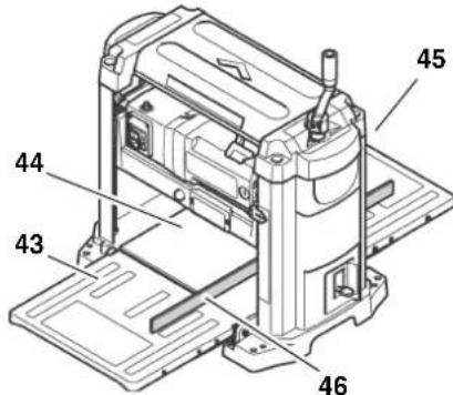
If readjustment is necessary:
- Fold both infeed and outfeed table up.
- Loosen lock nut (47) on both stop screws (48).
- Adjust both stop screws (48), until the infeed table (or outfeed table) is on a level with the centre table (44) of the thickening machine.
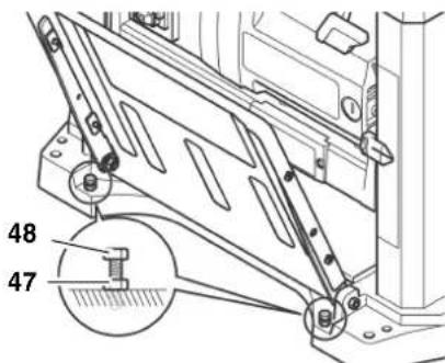
- Fold down the infeed table (or outfeed table) and recheck, if the bearing surfaces are now on a level with each other.
- When infeed and outfeed table are properly aligned, secure all stop screws (48) with the lock nuts (47).
6.3 Dust Collector

Danger!
Some types of wood dust (e.g. beech, oak, ash) can cause cancer when inhaled. To minimize the adverse effect of wood dust, you are strongly advised to connect a suitable dust collector to the machine when working indoors. The dust collector must comply with the following:
fitting the diameter of the dust extraction connector:
21/2" (64 mm), or
- 4^ (102 mm);
air flow volume ≥ 460m^3 /h
vacuum at the dust extraction connector ≥ 530Pa
air speed at dust extraction connector ≥ 20m / s
Follow the operating instructions supplied with the dust collector as well!
Operation without a dust collector is only advisable:
outdoors;
for short-term operation (up to a maximum of 30 minutes);
- when wearing a dust respirator.
If no dust collector is used chips will built up inside the machine housing, and on the planer knives in particular. These built-up chips cause the planed surface to become rough. Therefore the chips need to be removed periodically.

Danger!
The rotation of the cutterblock causes the chips to be blown through the slot in the cutterblock cover.

Caution!
The slot of the cutterblock cover or an installed dust extraction connector must not be blocked by objects placed in the path of ejected chips.
Installing the dust extraction connector

Cutting hazard when touching a stating cutterblock!
Accidental starting of the machine may cause serious injury. Unplug power supply cable before installing the dust extraction connector!
- Set lock lever fully to the left, into the position marked G
-
Lower cutterblock head, until the screws (50) of the cutterblock cover are easily accessible.
-
Loosen screws (50), until the dust extraction connector can be put on.
- Attach the dust extraction port (49) on the cutterblock cover, so that the upper recesses fit under the screws of the cutterblock cover.
- Screw holding pins (52) in the mounting holes (51) and tighten hand-tight. The dust extraction connector shall rest securely on the holding pins.
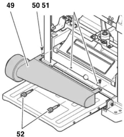
- Retighten the screws (50) of the cutter block cover.
6.4 Mains Connection

Danger! High voltage
- Operate this machine in dry surroundings only.
- Operate the machine only on a power source meeting the following requirements (see also "Technical specifications"):
outlets properly installed, earthed, and tested.
- mains voltage and system frequency conforming to the voltage and frequency shown on the machine's rating label;
- fuse protection by a residual current operated device (RCD) of 30mA sensitivity;
- System impedance Z_ at the interconnection point (house service connection) 0.38 Ohm maximum.

Note:
Check with your local Electricity Board or electrician if in doubt whether your house service connection meets these requirements.
- Position power supply cable so it does not interfere with the work and is not damaged.
-
Protect power supply cable from heat, aggressive liquids and sharp edges.
-
Use only rubber-jacketed extension cables of sufficient lead cross-section (see "Technical specifications").
- Do not pull on power supply cable to unplug.
7. Operation

Danger!
- This machine may only be operated by one person at a time. Other persons shall stay only at a distance to the machine for the purpose of feeding or removing stock.
-
Use personal protection gear:
-
dust respirator;
hearing protection; -
safety goggles.
-
Before starting work, check to see that the following are in proper working order:
-
power cable and plug;
- ON/OFF switch
-
cutterblock cover
push stick. -
Assume proper operating position when thicknessing:
-
at the front of the machine;
to the side of the infeed table;
when working with two persons, the second person must stay at a sufficient distance to the thickening machine and stand to the side of the infeed or outfeed table, respectively.
If the type of work requires, use the following:
- work piece support (e.g. roller support) - to keep the machine from tipping over when working long work pieces;
push stick (feeding aid) - for short work pieces; -
dust collector;
sliding wax - to enhance gliding of the work pieces through the machine, apply a light coat of sliding wax to the surfaces of infeed and outfeed table. -
Avoid typical operator mistakes:
-
Do not exceed the specified work piece dimensions.
- Do not jam the work piece. Risk of kickback.
Before planing a work piece
Test the machine when idling:
- Fold down both infeed and outfeed table.
-
Make sure the planer knives can turn freely.
-
Set lock lever fully to the left, into the position marked G
- Raise cutterblock head to at least 1 inch (25 mm) planing thickness.
- Set lock lever fully to the right, to the position marked
- Plug in the power supply cable's plug and start the motor (press green switch button).
-
Once the machine has reached full speed, pay attention to:
-
noise
- vibrations

If noise and/or vibrations appear to be unusually high: turn OFF the machine immediately and unplug!
- Check machine for parts that may have worked loose; fasten any loose parts properly, where necessary.
7.1 Planing Work Pieces
The thickness planer can remove a maximum of 1/8'' (3 mm) in a single pass. However, this depth of cut may be used only:
with very sharp planer knives;
- when planing soft wood;
- when the maximum work piece width is not used.
Otherwise there is a risk of overloading the machine.
- It is strongly recommended that you make several passes at a moderate depth of cut, to achieve the desired work piece thickness.

The ideal depth of cut to be used depends on a number of factors, such as type of wood, work piece width or the state of dryness of the wood.
If you are planing mainly very wide (13 inch (330mm) ) work pieces, the motor is subjected to heavy loads.
- Plane narrow work pieces in between, or take a break to relieve the motor.
Work piece dimensions
- Do not work work pieces which are shorter than 14 inch (356 mm). With shorter work pieces there is a risk of kickback!
- Do not work work pieces which are shorter than 3/16 " (5 mm). The cutter block head cannot be set lower.
Work only work pieces which are wider than 3 / 4 (19 mm). -
Use extra work piece supports for work pieces which are longer than 5 feet (1500 mm).
-
Never thickness several work pieces at the same time. Risk of personal injury if individual pieces are uncontrolled caught by the cutterblock.
- Fold down both infeed and outfeed table.
- Set the planing thickness with the crank (53). The planing thickness is indicated by the scale (54).

Adjust the planing thickness only when the cutterblock is at standstill!
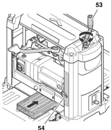
- Start motor (press green switch button).

- Never reach with your hands into the machine when guiding the workpiece!
- Guide a work piece on the outfeed side if it has been fed so far into the thicknesser that it can no longer be safely guided from the infeed side.
-
Never force the work piece into the machine by pushing or shoving. The machine will draw the work piece in automatically with the infeed roller.
-
Slide work piece slowly over the infeed table. It will then be automatically fed through the thicknesser.
- Guide work piece straight through the thicknesser.
- Switch machine off if no further planning is to be done immediately afterwards.
Planing with the final thickness stop
- Set lock lever fully to the left, into the position marked
-
Raise cutterblock head and set to a planing thickness of more than 13/4'' (44 mm).
-
Set the final thickness stop (55) to the desired thickness of the workpiece.
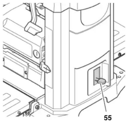
- Lower the cutterblock head, until it is stopped by the final thickness stop. Possibly the work piece needs to be planed down to a thickness which will permit it to be planed down to the final thickness in the last pass.
- Set lock lever fully to the right, to the position marked G
- Start motor (press green switch button) and plane the work piece.
8. Care and Maintenance
Prior to all servicing:
- switch machine OFF;
- Wait until the cutterblock has come to a complete stop.
- Unplug power cable.

Accidental starting of the machine may cause serious injury.

Right after planing the planer knives may be hot - let the machine cool down before servicing.
The checks and procedures described here are meant to help operate the machine safely! Should there be faults evident on any of these components, the machine must not be used until these faults have been remedied in a workman-like manner.
Repair and maintenance work other than described in this section should only be carried out by qualified spec. cialists.
- Check power supply cable for damages.
Never use the machine when the power supply cable is damaged. Risk of personal injury by electric shock. Have a damaged power supply cable replaced by a qualified electrician immediately.
ENG ENGLISH
- Replace defective parts, especially of safety devices, only with genuine replacement parts. Parts not tested and approved by the manufacturer can cause unforeseen damage.
After all servicing:
- Check to see that all safety devices are operational.
Make sure that no tools or other parts remain on or in the machine.
8.1 Machine Cleaning and Lubrication
Danger!
Some types of wood dust (e.g. beech, oak, ash) can cause cancer when inhaled.
When cleaning the machine wear dust respirator and safety goggles, to protect yourself from wood dust or splinters.
Caution!
- For cleaning, do not use solvents or cleaning agents containing solvents. The machine's plastic parts may be affected and damaged by the use of solvents.
- Never let petrol, petroleum-based products, or similar substances get in contact with the plastic parts of the machine. These substances contain chemicals which may damage, weaken, or destroy plastics.
- Remove dirt and wood dust with a clean cloth.
After each use
- Remove planing chips and wood dust from all accessible areas, incl. the dust extraction connector and/or the slot in the cutterblock cover (e.g. with a vacuum cleaner).
- Clean both infeed and outfeed roller. Any deposit, which may have formed on the rollers, can be removed with a non-flammable cleaning agent for rubber rollers.
Periodic cleaning
Soiling of the machine by wood dust or dirt may be the reason for poorly planned work pieces. For perfect planing results the machine should be preiodically cleaned and the bearing surfaces of the tables waxed.
- Unplug power cable.
- Fold down both infeed and outfeed table.
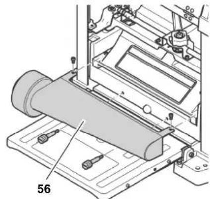
- Unscrew and remove the dust extraction connector (56) and clean with a cloth.
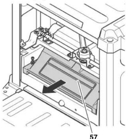
- Unscrew and remove the cutterblock cover (57) and clean with a cloth.
- Remove planing chips (e.g. with a vacuum cleaner) from:
height adjustment;
- cutterblock;
motor ventilation slots.
- Clean guide bars and spindles of the height adjustment with spray oil (e.g. WD40), then apply a light film of medium viscosity machine oil.
- Replace and fasten the cutterblock cover (57).
- Replace and fasten the dust extraction connector (56).
- Apply a light coat of wax for better gliding of the work piece on:
Infeed table
centre table
outfeed table
i Note:
Apply only a thin coat of wax. Too much wax may be absorbed by the wood, causing discolouration.
Tips for lubrication
Periodically check that guide bars and spindles of the height adjustment are clean and lightly oiled. Use a machine oil of medium viscosity.
The planer knives should also be given a light coat of oil, to inhibit rust.
- All bearings in this machine are lubricated with a high-grade grease. Under normal operating conditions this does provide sufficient lubrication for the entire service life of the machine. Additional lubrication is not required.
Cleaning the motor
As long as it is kept clean, the motor does not require any maintenance.
Make sure that on or in the motor no deposits of water, oil or wooddust build up.
The motor bearings do not require any lubrication.
8.2 Changing the Planer Knives
i Note:
Dull planer knives are recognizable by:
- reduced planing performance;
- increased risk of kickback;
motor overloads.
Danger!
Risk of personal injury by cuts from the planer knives!
- Wear gloves when changing planer knives.
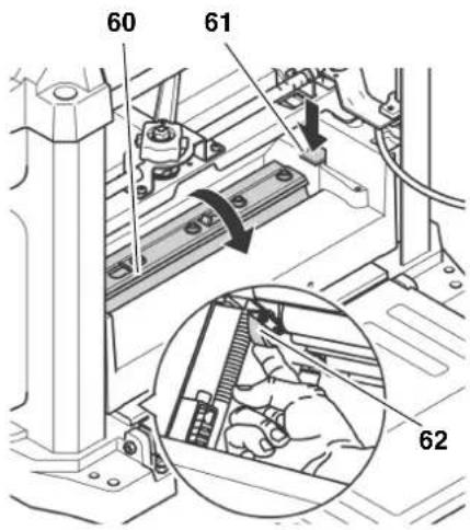
- Never turn the cutterblock directly by hand. When changing the planer knives, only turn the cutterblock by the drive belt (62).
Preparations
- Unplug power cable.
- Fold down both infeed and outfeed table.
- Unscrew and remove the dust extraction connector (58).

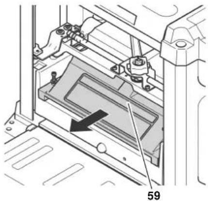
- Unscrew and remove the cutterblock cover (59).
Turning the cutterblock into the correct position
T ur n c u t t e r b belt (62), until the cutterblock is arrested.
To access the drive belt from below, raise the cutterblock head until the drive belt is accessible.
To have access to the second planer knife, the cutterblock must be rotated by 180^
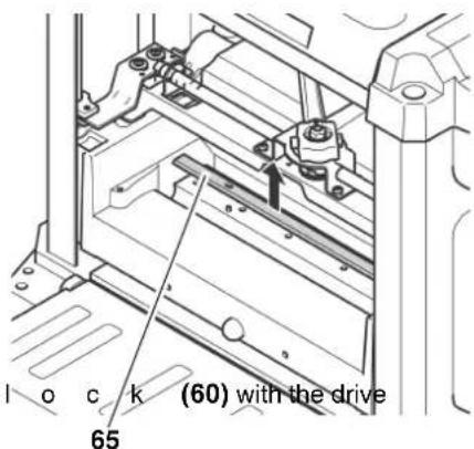
Press lock lever (61) and turn cutterblock with the drive belt (62).
- Release lock lever (61) and keep turning the cutterblock, until it is arrested in the new position.
Removing the planer knives
- Loosen all screws (64) of the planer knife lockbar with the Allen wrench and remove them (wear gloves!).
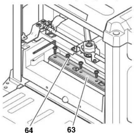
- Reabove the planer knife lockbar (63).
- Using the magnet of the special knife changing tool (65), lift the knives out of the cutterblock.
- Remove the two spring from the holes in the cutterblock.
- Clean all surfaces of cutterblock and planer knife lockbar with a suitable solvent.
Danger!
Do not use any cleaning agents (e.g. to remove resin residue) that could corrode the light metal components of the machine; the stability of the light metal components would be compromised.
Installing the planer knives
Danger!
- Use only suitable planer knives conforming to EN 847-1 (see "Available Accessories") - unsuitable, incorrectly mounted, blunt or damaged planer knives can work loose or increase the risk of kickback considerably.
Always replace or reverse both planer knives. -
Install planer knives using only genuine replacement parts.
-
Fit both springs into the holes in the cutterblock.
- Apply a light coat of oil to the planer knife.
- Position the planer knife with the special knife changing tool on the cutterblock. The two guide pins in the cutterblock ensure the planer knife is in the proper position.
i Note:
The planer knife has a cutting edge on both front and rear side. If the edge on the rear is sufficiently sharp, it will suffice to turn the knife.
- Tighten the planer knife lockbar: To avoid distortion of the planer knife lockbar start with the screws in the centre, then tighten the screws closer to the edges step by step.
Danger!
- Do not extend tool when tightening the bolts.
-
Do not tighten bolts by striking the wrench.
-
Replace and fasten the cutterblock cover.
- Make sure that no assembly tools or loose parts are remaining in the machine.
Test the machine when idling:
- Fold down both infeed and outfeed table.
- Make sure the planer knives can turn freely.
- Set lock lever fully to the left, into the position marked
- Raise cutterblock head to at least 1 inch (25 mm) planing thickness.
- Set lock lever fully to the right, to the position marked
- Plug in the power supply cable's plug and start the motor (press green switch button).
-
Once the machine has reached full speed, pay attention to:
-
noise
vibrations
Danger!
If noise and/or vibrations appear to be unusually high: turn OFF the machine immediately and unplug!
- Check machine for parts that may have worked loose; fasten any loose parts properly, where necessary.
8.3 Adjusting the Final Thickness Stop
- Using the final thickness stop, plane work piece to the desired stop measure.
- Measure the actual stop measure (= work piece thickness) of the workpiece.
If readjustment of the final thickness stop is necessary:
- Unplug power cable.
- Set lock lever fully to the left, into the position marked G
-
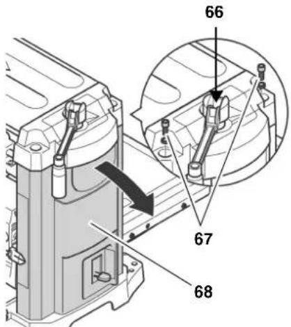
Loosen Phillips head screw (66) securing the crank of the height adjustment, but do not remove it.
-
Removing the side cover (68):
-
Remove both Allen head screws (67) (metric, 6 mm).
- Lift the machine's upper part at the carrying handle, then carefully remove the side cover (68).
- Lower the cutterblock head, until the final thickness stop (70) makes contact with the stop screw (69). When doing so, the final thickness stop must be set to the above set stop measure.
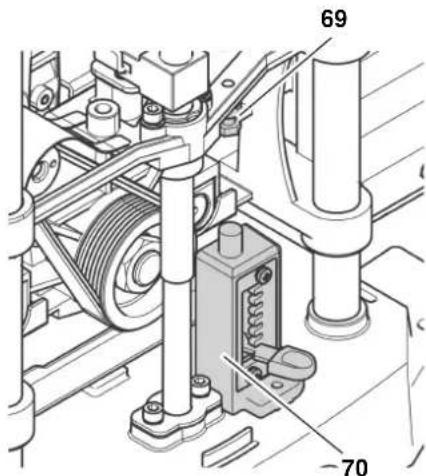
- Loosen the lock nut of the stop screw (69) with the open jaw wrench (metric, 10mm ), and adjust the stop screw by the difference between the set stop measure and the measured actual thickness of the work piece.
- Secure the stop screw (69) in position with the lock nut.
- Reinstall the side cover (68) and fasten with the two Allen head screws (67).
- Retighten the Phillips head screw (66) securing the crank of the height adjustment, handtight only.
8.4 Checking and Replacing the Carbon Brushes
Both front and rear carbon brushes should be checked every 10 to 15 operating hours.
Worn carbon brushes are recognizable by:
intermittent operation of motor;
- Interference in radio and TV reception while the motor is running;
motor stalling.
To check or replace carbon brushes:
- Unplug power cable.
- Fold down both infeed and outfeed table.
- Remove the carbon brush on the infeed side of the machine: unscrew the plug (71) from the motor housing with a suitable screwdriver.
i Note:
The rear carbon brush is located on the opposite (outfeed) side. To remove the rear carbon brush, the dust extraction adaptor and the cutterblock cover need to be removed first.
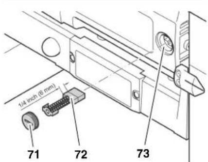
4.Pull carbon brush 72) out and check.Each carbon brush should be at least 1 / 4'' 6 mm long.
5. Fit intact or new carbon brush (72) into the carbon holder (73). The two lugs on the sides of the small metal plate must fit into the grooves in the brush holder.
- Replace the plug (71).
i Note:
After replacement of the rear carbon brush, both the cutterblock cover and the dust extraction connector must be reinstalled and securely fastened.
- Check the functioning of the machine.
8.5 Storage
- Unplug and stow away the power supply cable in the pocket on the underside of the outfeed table.
- Swing both infeed and outfeed table up.
-
Store machine in a way that
-
it cannot be used or tempered with by unauthorized persons, and
- nobody can get hurt by the stored machine.
Caution!
Do not store machine unprotected outdoors or in damp environment.
8.6 Transport
- Unplug power supply cable.
- Unscrew and remove the dust extraction connector (74).
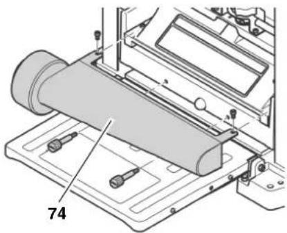
- Swing both infeed and outfeed table up.
- Stow away the power supply cable in the pocket on the underside of the outfeed table.
- Transport machine holding it by the carrying handles on its sides.
Caution!
Never store the machine outdoors, in unprotected areas or in damp or wet locations.
9. Troubleshooting
Danger!
Before carrying out any fault service or maintenance work, always:
- switch machine OFF;
- Wait until the cutterblock has come to a complete stop.
- Unplug power cable.
Cutting hazard when touching the rotating cutterblock!
Accidental starting of the machine may cause serious injury.
!Burning hazard!
Right after planing the planer knives may be hot - let the machine cool down before troubleshooting.
Danger!
After each service, enable all safety devices and check to see that they are fully operational.
Motor does not run
No supply voltage.
- Check cables, plug, outlet and mains fuse.
Undervoltage relay tripped by temporary voltage failure.
- Start again.
Motor has overheated, e.g. due to blunt planer knives, overloading or chips jammed inside the cutterblock cover.
- Remove cause for overheating, let cool down for approx. 10 minutes, then press the reset button and restart the machine.
Carbon brushes worn down.
Replace carbon brushes.
Performance lessens
Install sharp knives.
Planed surface not smooth
Install sharp knives.
Planer knives blocked by chips.
- Remove chips.
Moisture contents of work piece too high.
Dry work piece.
Planed surface cracked
Install sharp knives.
Planer knives blocked by chips.
- Remove chips.
Work piece was planed against the grain.
- Plane work piece in opposite direction.
Too much material removed in one pass.
- Make several passes at less depth of cut.
Worked surface uneven:
Planer knives are installed uneven.
- Adjust planer knives with setting gauge.
Feed rate too little
Resin built-up on bearing surfaces of centre table, infeed table or outfeed table.
Clean bearing surfaces and apply a light coat of sliding wax.
Work piece jammed
Too much material removed in one pass.
- Make several passes at less depth of cut.
10. Available Accessories
For special tasks the following accessories are available at your specialized dealer - see back cover for illustrations:
A Work Stand
For a secure machine stand and optimal working height; folding, ideal for mobile use.
B Dust Extraction Connector To connect to a dust collector
C Three Roller Support To support long work pieces
D Planer Knives For planing wood
E WAXILIT Anti-seize Compound Sliding wax to improve stock gliding quality on the planing beds.
F Care and Maintenance Spray Removes resin residue and preserves metal surfaces
11. Repairs
Danger!
Repairs to power tools must only be carried out by qualified electricians!
Electric tools in need of repair can be sent to the service centre of your country. Refer to the spare parts list for the address.
Please attach a description of the fault to the machine.
- Technical Specifications
| Voltage V 230 ~ 50 Hz 110 ~ 50 Hz | ||||
| Fuse protection min. A 10 16 | ||||
| Motor capacity W 1800 1620 | ||||
| Degree of protection IP 20 20 | ||||
| Protection class II | ||||
| No-load speed (cutterblock) min | -1 | 9800 9100 | ||
| Feed rate m/min 7.5 7.5 | ||||
| Depth of cut maximum | mm | 3 | 3 | |
| Work piece thickness minimum | mm | 5 | 5 | |
| Work piece width maximum | mm | 152 | 152 | |
| mm | 19 | 19 | ||
| mm | 330 | 330 | ||
| Work piece length minimum | mm | 356 | 356 | |
| Dimensions depth (tables folded up) | mm | 350 | 350 | |
| Dimensions depth (thickness table) | mm | 585 | 585 | |
| Dimensions width (thickness table) | mm | 495 | 495 | |
| Weight | kg | 35 | 35 | |
| Permissible ambient operating temperature range | °C | 0 to +40 | 0 to +40 | |
| Permissible transport and storage temperature range | °C | 0 to +40 | 0 to +40 | |
| Noise emission values according to EN 61029-1* | ||||
| Dust collector inner diameter of dust extraction connector | dB (A) | 88 | 88 | |
| dB (A) | 101 | 101 | ||
| dB (A) | 3 | 3 | ||
| Vacuum at suction connector | 64 | 64 | ||
| air flow volume | 102 | 102 | ||
| air speed at suction connector | 460 | 460 | ||
| m/s | 530 | 530 | ||
| m/s | 20 | 20 | ||
- The values stated are emission values and as such do not necessarily constitute values which are safe for the workplace. Although there is a correlation between emission levels and environmental impact levels, whether further precautions are necessary cannot be derived from this. Factors influencing the actually present environmental impact level in the workplace include the characteristics of the work area and other noise sources, i.e. the number of machines and other neighbouring work processes. Also, permissible workplace values may vary from country to country. This information is intended to assist the user in his estimate of hazards and risks.
D0911063549E0911001071F0911018691


- Bernd Fleischmann
- Parts Identification
- Working principle of a thicknessing machine
- Standard delivery parts and tools
- Components inside the thicknessing machine
- Table of Contents
- Please Read First!
- Safety
- Specified Conditions of Use
- General Safety Instructions
- Caution!
- General hazards!
- Danger! Risk of electric shock!
- Cutting hazard when touching
- the rotating cutterblock!
- Cutting hazard, even with the block at standstill!
- Drawing-in/trapping hazard!
- Risk of injury by work piece back (work piece is caught by the cutting cutterblock and thrown back to the operator)!
- Hazard generated by insuffi- personal protection gear!
- Risk of injury by inhaled wood
- Hazard generated by modifica- of the machine, or use of parts- sted and approved by the manu- rer!
- Hazard generated by machine
- defects!
- Danger from blocking work- s or workpiece parts!
- Symbols on the Machine
- Danger!
- Information on the nameplate:
- Safety Devices
- Cutterblock cover
- Special Product Features
- Operating Controls
- ON/OFF switch
- i Note:
- Height adjustment
- Lock lever for height adjustment
- Depth of cut indicator
- Final thickness stop
- Initial Operation
- Machine Installation
- Aligning the Infeed and Outfeed Tables
- Cutting hazard when touching the rotating cutterblock! Accidental starting of the machine may cause serious injury. Always unplug before making any adjustments to the machine!
- Dust Collector
- Mains Connection
- Danger! High voltage
- Note:
- Operation
- Before planing a work piece
- If noise and/or vibrations appear to be unusually high: turn OFF the machine immediately and unplug!
- Planing Work Pieces
- Work piece dimensions
- Adjust the planing thickness only when the cutterblock is at standstill!
- Planing with the final thickness stop
- Care and Maintenance
- Prior to all servicing:
- Right after planing the planer knives may be hot - let the machine cool down before servicing.
- ENG ENGLISH
- After all servicing:
- Machine Cleaning and Lubrication
- After each use
- Periodic cleaning
- Tips for lubrication
- Cleaning the motor
- Changing the Planer Knives
- Preparations
- Turning the cutterblock into the correct position
- Removing the planer knives
- Installing the planer knives
- Adjusting the Final Thickness Stop
- Checking and Replacing the Carbon Brushes
- Storage
- Transport
- Troubleshooting
- Cutting hazard when touching the rotating cutterblock!
- !Burning hazard!
- Motor does not run
- Performance lessens
- Planed surface not smooth
- Planed surface cracked
- Worked surface uneven:
- Feed rate too little
- Work piece jammed
- Available Accessories
- Repairs
- Repairs to power tools must only be carried out by qualified electricians!
Brand : METABO
Model : DH 330
Category : Plane