
WHADC1216H6E5C - Air-conditioner PANASONIC - Free user manual and instructions
Find the device manual for free WHADC1216H6E5C PANASONIC in PDF.
| Product type | Air-to-water heat pump split with integrated 200 L domestic hot water tank |
| Brand | Panasonic |
| Model | WHADC1216H6E5C |
| Power supply | 230 V / 50 Hz, single phase |
| Refrigerant | R32 (flammable, class A2L) |
| Operating range (heating) | Outdoor temperature: -20 °C to 35 °C; Water outlet temperature: 20 °C to 65 °C |
| Operating range (cooling) | Outdoor temperature: 16 °C to 43 °C; Water outlet temperature: 5 °C to 20 °C |
| Indoor unit dimensions (approx.) | Height: 1,800 mm, Width: 600 mm, Depth: 700 mm (estimate for a 200 L tank) |
| Outdoor unit dimensions (approx.) | Height: 900 mm, Width: 1,200 mm, Depth: 400 mm (estimate for standard model) |
| Indoor unit weight (approx.) | Approximately 150 kg (tank + hydromodule) |
| Outdoor unit weight (approx.) | Approximately 80 kg |
| Main functions | Heating, cooling (unlock by installer), domestic hot water production, anti-legionella sterilization, weekly programming, vacation mode, silent mode, electric backup, weather-dependent control |
| Control type | Wired remote control with LCD screen, directional buttons, quick menu and main menu |
| Safety functions | Integrated residual current circuit breaker (RCCB/ELCB), frost protection, high/low pressure protection, compressor protection, automatic shutdown in case of anomaly |
| User maintenance | Cleaning the outdoor unit (remove snow, leaves), cleaning the water filter (at least once a year), checking the water pressure (0.05-0.3 MPa) |
| Professional maintenance | Seasonal inspection by authorized installer, checking RCCB/ELCB, internal cleaning, water filter maintenance |
| Spare parts and repairability | Parts available through Panasonic authorized installer network; repairs reserved for professionals; do not attempt to repair the indoor or outdoor unit yourself |
| Energy class (estimated) | A++ (heating) / A+ (cooling) depending on model |
| Optional accessories | Optional connectivity card (external PCB) for 2-zone management, solar, bivalence; network adapter for Panasonic Smart app |
| Certifications | Compliant with European standard 98/83 EC for water quality; compliance with WEEE directives |
Frequently Asked Questions - WHADC1216H6E5C PANASONIC
User questions about WHADC1216H6E5C PANASONIC
0 question about this device. Answer the ones you know or ask your own.
Ask a new question about this device
Download the instructions for your Air-conditioner in PDF format for free! Find your manual WHADC1216H6E5C - PANASONIC and take your electronic device back in hand. On this page are published all the documents necessary for the use of your device. WHADC1216H6E5C by PANASONIC.
USER MANUAL WHADC1216H6E5C PANASONIC
Operating Instructions
Air-to-Water Hydromodule + Tank
natural_image
Line drawing of a rectangular industrial machine with control panel and multiple ports (no text or symbols)Model No.
Indoor Unit
WH-ADC1216H6E5C
Outdoor Unit
WH-UD12HE5*
WH-UD16HE5*
WH-UX09HE5*
WH-UX12HE5*
Operating Instructions
Air-to-Water Hydromodule + Tank
Instrucciones de
funcionamiento
Hydrokit Aire-Agua + Tanque
Thank you for purchasing Panasonic product.
Before operating the system, please read these operating instructions thoroughly and keep them for future reference.
Installation Instructions attached.
Serial number and production year please refer to name plate.
Table of contents
Safety precautions 4-6
Remote Controller buttons and display 7-9
Initialization 9
Quick Menu 10
Menus 10-24
For user
1 Function setup 10-11
1.1 Weekly timer
1.2 Holiday timer
1.3 Quiet timer
1.4 Room heater
1.5 Tank heater
1.6 Sterilization
1.7 DHW mode
2 System check 12
2.1 Energy monitor
2.2 System information
2.3 Error history
2.4 Compressor
2.5 Heater
3 Personal setup 12-13
3.1 Touch sound
3.2 LCD contrast
3.3 Backlight
3.4 Backlight intensity
3.5 Clock format
3.6 Date & Time
3.7 Language
3.8 Unlock password
4 Service contact 13
4.1 Contact 1 / Contact 2
For installer
5 Installer setup > System setup .....14-19
5.1 Optional PCB connectivity
5.2 Zone & Sensor
5.3 Heater capacity
5.4 Anti freezing
5.5 Buffer tank connection
5.6 Base pan heater
5.7 Alternative outdoor sensor
5.8 Bivalent connection
5.9 External SW
5.10 Solar connection
5.11 External error signal
5.12 Demand control
5.13 SG ready
5.14 External compressor SW
5.15 Circulation liquid
5.16 Heat-Cool SW
5.17 Force heater
5.18 Defrost signal
5.19 Pump flowrate
6 Installer setup > Operation setup .....19-23
6.1 Heat
6.2 Cool
6.3 Auto
6.4 Tank
7 Installer setup > Service setup .....23-24
7.1 Pump maximum speed
7.2 Pump down
7.3 Dry concrete
7.4 Service contact
Cleaning instructions 25
Troubleshooting 26-27
Information 28-29

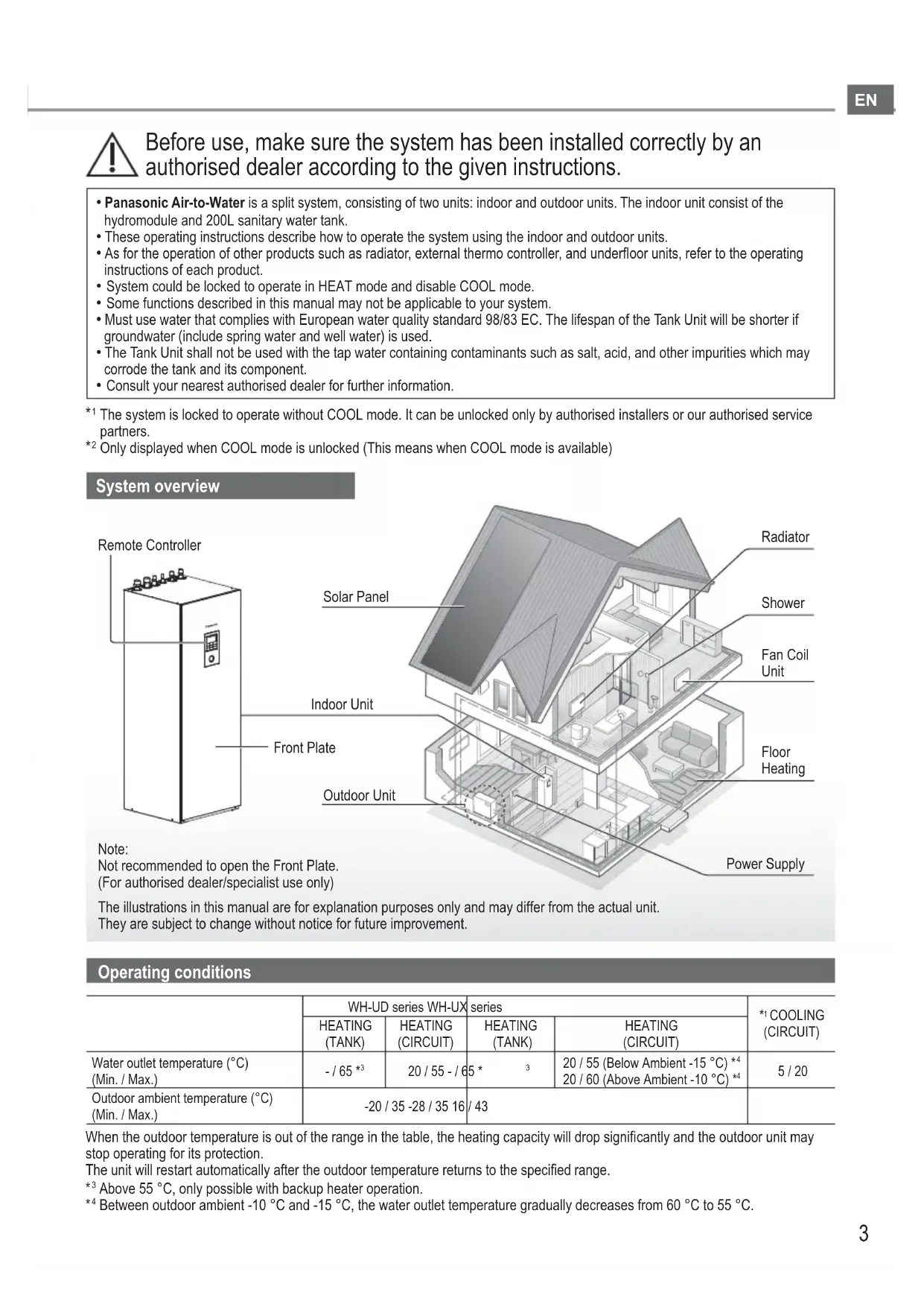
Before use, make sure the system has been installed correctly by an authorised dealer according to the given instructions.
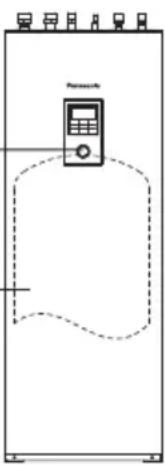
- Panasonic Air-to-Water is a split system, consisting of two units: indoor and outdoor units. The indoor unit consists of the hydromodule and 200L sanitary water tank.
• These operating instructions describe how to operate the system using the indoor and outdoor units. - As for the operation of other products such as radiator, external thermo controller, and underfloor units, refer to the operating instructions of each product.
- System could be locked to operate in HEAT mode and disable COOL mode.
- Some functions described in this manual may not be applicable to your system.
- Must use water that complies with European water quality standard 98/83 EC. The lifespan of the Tank Unit will be shorter if groundwater (include spring water and well water) is used.
- The Tank Unit shall not be used with the tap water containing contaminants such as salt, acid, and other impurities which may corrode the tank and its component.
- Consult your nearest authorised dealer for further information.
*1 The system is locked to operate without COOL mode. It can be unlocked only by authorised installers or our authorised service partners.
*2 Only displayed when COOL mode is unlocked (This means when COOL mode is available)
System overview
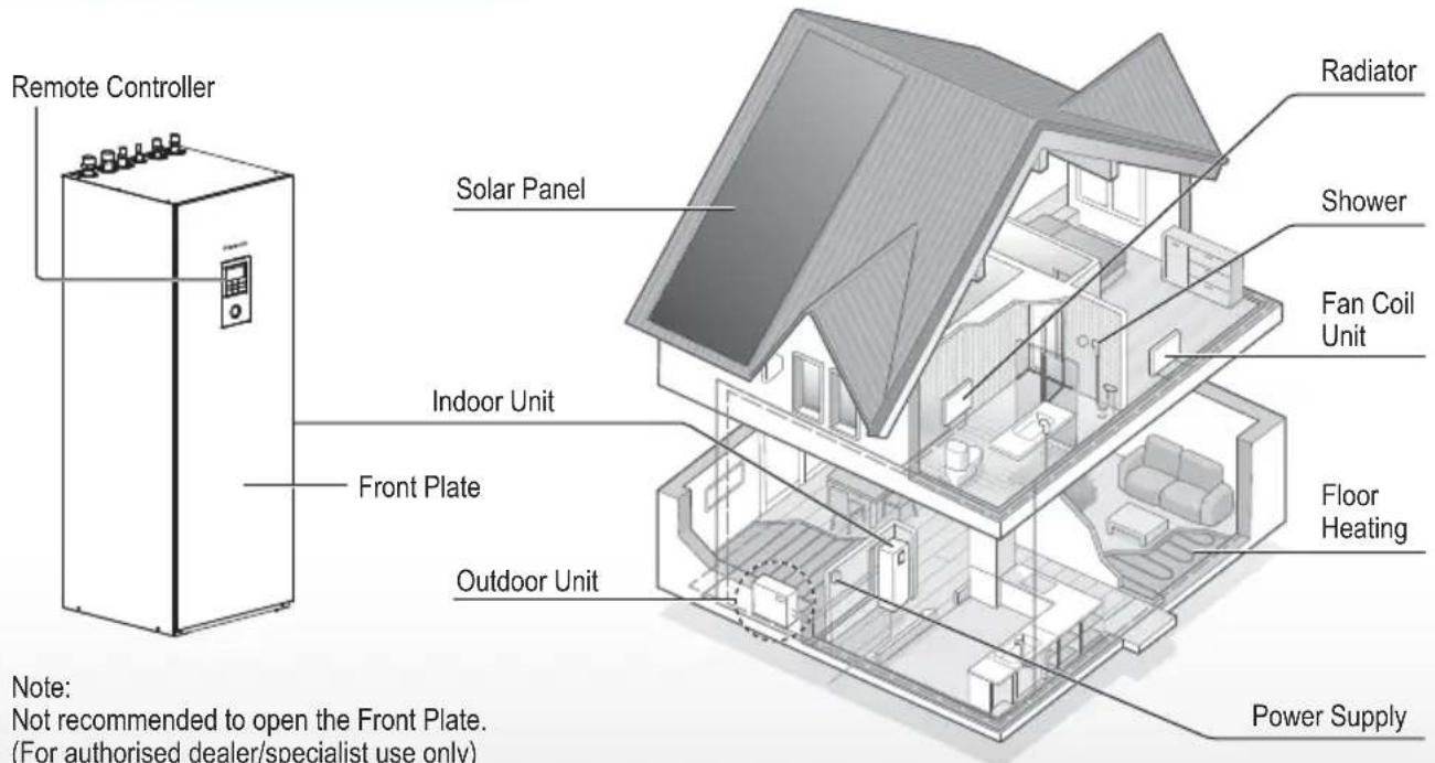
The illustrations in this manual are for explanation purposes only and may differ from the actual unit. They are subject to change without notice for future improvement.
Operating conditions
| WH-UD series WH-UX | series | *1 COOLING (CIRCUIT) | |||
| HEATING (TANK) | HEATING (CIRCUIT) | HEATING (TANK) | HEATING (CIRCUIT) | ||
| Water outlet temperature (°C) (Min. / Max.) | - / 65 *3 | 20 / 55 - / 65 * | 3 | 20 / 55 (Below Ambient -15 °C) *420 / 60 (Above Ambient -10 °C) *4 | 5 / 20 |
| Outdoor ambient temperature (°C) (Min. / Max.) | -20 / 35 -28 / 35 16 / 43 | ||||
When the outdoor temperature is out of the range in the table, the heating capacity will drop significantly and the outdoor unit may stop operating for its protection.
The unit will restart automatically after the outdoor temperature returns to the specified range.
*3 Above 55 °C, only possible with backup heater operation.
*4 Between outdoor ambient -10 °C and -15 °C, the water outlet temperature gradually decreases from 60 °C to 55 °C.
To prevent personal injury, injury to others or property damage, please comply with the following:
Incorrect operation due to failure to follow instructions below may cause harm or damage, the seriousness of which is classified as below:
This appliances is not intended for accessibility by the general public.

WARNING
This sign warns of death or serious injury.

CAUTION
This sign warns of injury or damage to property.
The instructions to be followed are classified by the following symbols:

This symbol denotes an action that is PROHIBITED.


These symbols denote actions COMPULSORY.

WARNING
Indoor unit and outdoor unit

This appliance can be used by children aged from 8 years and above and persons with reduced physical, sensory or mental capabilities or lack of experience and knowledge if they have been given supervision or instruction concerning use of the appliance in a safe way and understand the hazards involved. Children shall not play with the appliance. Cleaning and user maintenance shall not be made by children without supervision.
Please consult an authorised dealer or specialist to clean the internal parts, repair, install, remove, disassemble and reinstall the unit. Improper installation and handling will cause leakage, electric shock or fire.
Confi rm with authorised dealer or specialist on usage of any specified refrigerant type. Using refrigerant type other than the specified may cause product damage, burst and injury etc.

Do not use means to accelerate the defrosting process or to clean, other than those recommended by manufacturer.
Any unfit method or using incompatible material may cause product damage, burst and serious injury.
Do not install the unit in a potentially explosive or fl ammable atmosphere. Failure to do so could result in fi re.

Do not insert your fingers or other objects into the Air to water indoor or outdoor unit, rotating parts may cause injury.

Do not touch the outdoor unit during lightning, it may cause electric shock.
Do not sit or step on the unit, you may fall down accidentally.

Do not install the indoor unit outdoors. This is designed for indoor installation only.
Power supply

Do not use a modified cord, joint cord, extension cord or unspecified cord to prevent overheating and fire.


To prevent overheating, fire or electric shock:
- Do not share the same power outlet with other equipment.
- Do not operate with wet hands.
- Do not over bend the power supply cord.

If the supply cord is damaged, it must be replaced by the manufacturer, service agent or similarly qualified persons in order to avoid a hazard.
This unit is equipped with Residual Current Circuit Breaker/Earth Leakage Circuit Breaker (RCCB/ELCB). Ask an authorised dealer to check RCCB/ELCB operation regularly, especially after installation, inspection, and maintenance. RCCB/ELCB malfunction may result in electric shock and/or fire.

It is strongly recommended that Install Residual Current Device (RCD) on-site to prevent electric shock and/or fire.
Before obtaining access to terminals, all supply circuits must be disconnected.
Stop using the product if any abnormality/failure occurs and disconnect the power supply. (Risk of smoke/fi re/electric shock)
Examples of abnormality/failure
• RCCB/ELCB trips frequently.
- Burning smell is observed.
- Abnormal noise or vibration of the unit is observed.
- Hot water leaks from the indoor unit. Contact your local dealer immediately for maintenance/repair.
Wear gloves during inspection and maintenance.

This equipment must be earthed to prevent electrical shock or fire.

Prevent electric shock by switching off the power supply: - Before cleaning or servicing, - When extended non-use.
This appliance is for multiple uses. To avoid electric shock, burn and/or fatal injury, make sure to disconnect all power supplies before accessing any terminal in the indoor unit.

CAUTION
Indoor unit and outdoor unit

Do not wash the indoor unit with water, benzine, thinner or scouring powder to avoid damage or corrosion at the unit.
Do not install the unit close to any combustibles or at bathroom. Otherwise, it may cause electric shock and/or fi re.
Do not touch the sharp aluminium fi n, sharp parts may cause injury.

Do not use the system during sterilisation in order to prevent scalding with hot water, or overheating of shower.
Do not dismantle the unit for cleaning purpose to avoid injury.
Do not step onto an unstable bench when cleaning the unit to avoid injury.
Do not place a vase or water container on the unit. Water may enter the unit and degrade the insulation. This may cause an electric shock.

Prevent water leakage by ensuring drainage pipe is:
-Connected properly,
-Kept clear of gutters and containers, or
-Not immersed in water
After a long period of use or use with any combustible equipment, aerate the room regularly.
After a long period of use, make sure the installation rack does not deteriorate to prevent the unit from falling down.
Remote Controller

Do not wet the Remote Controller. Failure to do so may result in electric shock and/or fire.
Do not press the buttons on the Remote Controller using hard and sharp objects. Failure to do so may cause damage to the unit.
Do not wash the Remote Controller using water, benzine, thinner or scouring powder.
Do not inspect or maintain the Remote Controller by yourself. Consult an authorised dealer in order to prevent personal injury caused by incorrect operation.
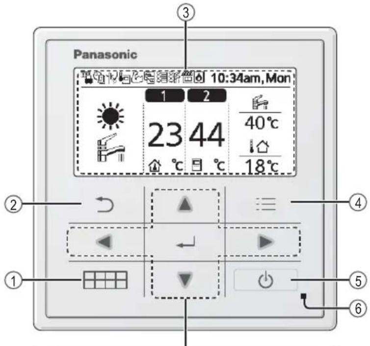
Remote Controller buttons and display
EN
| Buttons / Indicator | |
| 1 | Quick Menu button(For more details, refer to the separate Quick Menu Guide.) |
| 2 | Back buttonReturns to the previous screen |
| 3 | LCD Display |
| 4 | Main Menu buttonFor function setup |
| 5 | ON/OFF buttonStarts/Stops operation |
| 6 | Operation indicatorIlluminates during operation, blinks during alarm. |
Safety precautions / Remote Controller buttons and display

Press centre
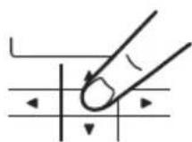
Cross key buttons
Selects an item.
Enter button
Fixes the selected content.

No glove

natural_image
Hand pointing at a grid with directional arrows (no text or symbols)
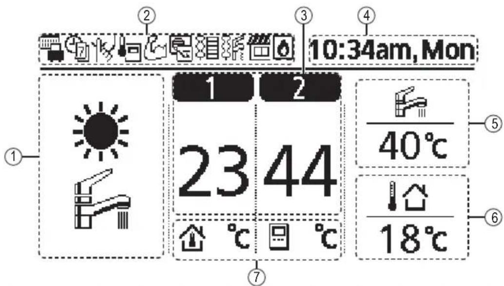
No pen

natural_image
Hand holding a pen writing on a grid with arrows indicating direction (no text or symbols present)Remote Controller buttons and display
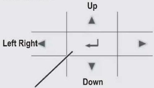
Display
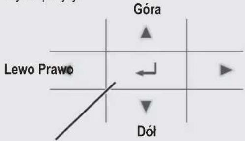
① Mode selection
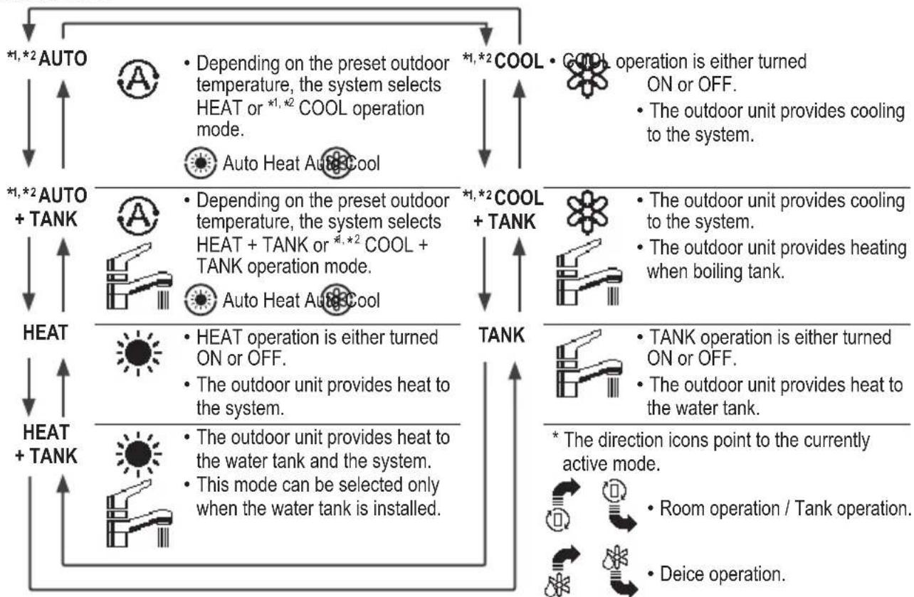
flowchart
graph TD
    A["HOAT + TANK"] --> B["HEAT"]
    B --> C["HEAT + AUTO"]
    D["COOL + TANK"] --> E["COOL operation is either turned ON or OFF."]
    E --> F["The outdoor unit provides cooling to the system."]
    G["TANK"] --> H["The outdoor unit provides cooling to the system."]
    H --> I["The outdoor unit provides heating when boiling tank."]
    J["HEAT + TANK"] --> K["HEAT operation is either turned ON or OFF."]
    K --> L["The outdoor unit provides heat to the system."]
    M["COOL + TANK"] --> N["COOL operation is either turned ON or OFF."]
    N --> O["The outdoor unit provides cooling to the system."]
    P["HEAT + AUTO + TANK"] --> Q["HEAT operation is either turned ON or OFF."]
    Q --> R["The outdoor unit provides heat to the system."]
    S["COOL + TANK"] --> T["COOL operation is either turned ON or OFF."]
    T --> U["The outdoor unit provides cooling to the system."]
    V["HEAT + AUTO"] --> W["HEAT operation is either turned ON or OFF."]
    W --> X["The outdoor unit provides heat to the system."]
    Y["COOL + TANK"] --> Z["COOL operation is either turned ON or OFF."]
    Z --> AA["The outdoor unit provides cooling to the system."]
    AB["HEAT + AUTO"] --> AC["HEAT operation is either turned ON or OFF."]
    AC --> AD["The outdoor unit provides heat to the system."]
    AE["COOL + TANK"] --> AF["COOL operation is either turned ON or OFF."]
    AF --> AG["The outdoor unit provides cooling to the system."]
    AH["HEAT + AUTO"] --> AI["HEAT operation is either turned ON or OFF."]
    AI --> AJ["The outdoor unit provides heat to the system."]
    AK["COOL + TANK"] --> AL["COOL operation is either turned ON or OFF."]
    AL --> AM["The outdoor unit provides cooling to the system."]
    AN["HEAT + AUTO"] --> AO["HEAT operation is either turned ON or OFF."]
    AO --> AP["The outdoor unit provides heat to the system."]
    AQ["COOL + TANK"] --> AR["COOL operation is either turned ON or OFF."]
    AR --> AS["The outdoor unit provides cooling to the system."]
    AT["HEAT + AUTO"] --> AU["HEAT operation is either turned ON or OFF."]
    AU --> AV["The outdoor unit provides heat to the system."]
    AW["COOL + TANK"] --> AX["COOL operation is either turned ON or OFF."]
    AX --> AY["The outdoor unit provides cooling to the system."]
    AZ["HEAT + AUTO"] --> BA["HEAT operation is either turned ON or OFF."]
    BA --> BB["The outdoor unit provides heat to the system."]
    BC["COOL + TANK"] --> BD["COOL operation is either turned ON or OFF."]
    BD --> BE["The outdoor unit provides cooling to the system."]
    BF["HEAT + AUTO"] --> BG["HEAT operation is either turned ON or OFF."]
    BG --> BH["The outdoor unit provides heat to the system."]
    BI["COOL + TANK"] --> BJ["COOL operation is either turned ON or OFF."]
    BJ --> BK["The outdoor unit provides cooling to the system."]
    BL["HEAT + AUTO"] --> BM["HEAT operation is either turned ON or OFF."]
    BM --> BN["The outdoor unit provides heat to the system."]
    BO["COOL + TANK"] --> BP["COOL operation is either turned ON or OFF."]
    BP --> BQ["The outdoor unit provides cooling to the system."]
    BR["HEAT + AUTO"] --> BS["HEAT operation is either turned ON or OFF."]
    BS --> BT["The outdoor unit provides heat to the system."]
    BU["COOL + TANK"] --> BV["COOL operation is either turned ON or OFF."]
    BV --> BW["The outdoor unit provides cooling to the system."]
    BX["HEAT + AUTO"] --> BY["HEAT operation is either turned ON or OFF."]
    BY --> BZ["The outdoor unit provides heat to the system."]
    CA["COOL + TANK"] --> CB["COOL operation is either turned ON or OFF."]
    CB --> CC["The outdoor unit provides cooling to the system."]
    CD["TANK"] --> CE["TANK operation is either turned ON or OFF."]
    CE --> CF["The outdoor unit provides heat to the water tank."]
    CG["TANK"] --> CH["TANK operation is either turned ON or OFF."]
    CH --> CI["The outdoor unit provides heat to the water tank."]
    CJ["TANK"] --> CK["TANK operation is either turned ON or OFF."]
    CK --> CL["The outdoor unit provides heat to the water tank."]
    CM["TANK"] --> CN["TANK operation is either turned ON or OFF."]
    CN --> CO["The outdoor unit provides heat to the water tank."]
    CP["TANK"] --> CQ["TANK operation is either turned ON or OFF."]
    CQ --> CR["The outdoor unit provides heat to the water tank."]
    CS["TANK"] --> CT["TANK operation is either turned ON or OFF."]
    CT --> CU["The outdoor unit provides heat to the water tank."]
    CV["TANK"] --> CW["TANK operation is either turned ON or OFF."]
    CW --> CX["The outdoor unit provides heat to the water tank."]
    CY["TANK"] --> CZ["TANK operation is either turned ON or OFF."]
    CZ --> DA["The outdoor unit provides heat to the water tank."]
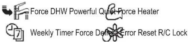
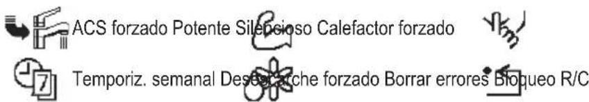
② Operation icons
The status of operation is displayed.
Icon will not display (under operation OFF screen) whenever operation is OFF except weekly timer.

Holiday operation status Weekly Further operation status Quiet operation status

Zone: Room Thermostat →Internal sensor status Powerful operation status

Room Heater status Tank Heater status Solar status

Bivalent status (Boiler)
*1 The system is locked to operate without COOL mode. It can be unlocked only by authorised installers or our authorised service partners. *2 Only displayed when COOL mode is unlocked (This means when COOL mode is available).
③ Temperature of each zone
④ Time and day
⑤ Water Tank temperature
⑥Outdoor temperature
⑦ Sensor type/Set temperature type icons


Water Temperature →Compensation curve Room Thermostat →External


Water Temperature →Direct Room Thermostat →Internal


Pool only
Room Thermistor
Initialization
Before starting to install the various menu settings, please initiate the Remote Controller by selecting the language of operation and installing the date and time correctly. When power is turned on for the first time, it becomes the setting screen automatically. It can also be set from personal setting of the menu.
Selecting the language
Wait while the display is initializing. When initializing screen ends, it turns to normal screen. When any button is pressed, language setting screen appears.
① Scroll with ▼ and ▲ to select the language.
② Press to confirm the selection.
Setting the clock
① Selectwith ▼ or ▲ how to display the time, either 24h or am/pm format (for example, 15:00 or 3:00 pm).
② Press to confirm the selection.
③ Use ▼ and ▲ to select year, month, day, hour and minutes. (Select and move with ▲ and press to confirm.)
④ Once the time is set, time and day will appear on the display even if the Remote Controller is turned OFF.
![Initialization 12:00am,Mon LCD blinking Initializing ... 12:00am,Mor Start Language 12:00am,Mor ENGLISH FRANÇAIS DEUTSCH ITALIANO Select [←]Confirm](/content/2026/03/487618/images/c6be3b400b30d96efb00c221a694871db86fb880798598186bf92f5e9cdbe327.jpg)
![Clock format 12:00am,Mon 24h am/pm Select [←]Confirm Date & Time 12:00am,Mon Year/Month/Day Hour : Min 2015 / 01 / 01 12 : 00 am Select [←]Confirm 10:00am,Wed Start](/content/2026/03/487618/images/f6070c4a48f2f0ccdc93f9fa1e1fb490e3c55d348bc5ad747171206626da74b0.jpg)
After the initial settings have been completed, you can select a quick menu from the following options and edit the setting.
① Press ☐ to display the quick menu.
![Select [←] ON/OFF](/content/2026/03/487618/images/756e956d82b7183ef8eb48ac4768d8ddca03290ccf9d02d661e41245b43ed064.jpg)


② Use ▲ to select menu.
③ Press to turn on/off the select menu.
Menus
For user
Select menus and determine settings according to the system available in the household. All initial settings must be done by an authorised dealer or a specialist. It is recommended that all alterations of the initial settings are also done by an authorised dealer or a specialist.
• After initial installation, you may manually adjust the settings.
- The initial setting remains active until the user changes it.
- The Remote Controller can be used for multiple installations.
- Ensure the operation indicator is OFF before setting.
- The system may not work properly if set wrongly.
Please consult an authorised dealer.
To display
To select menu: ▲ ▼ ◀ ▶
To confirm the selected content:
![Panasonic Main Menu 10:34am, Mon Function setup System check Personal setup Service contact Select [←] Confirm](/content/2026/03/487618/images/d5db3ad9a76f17a3f3a7a674a4218c7ccaa2cef62aaac4a99230d4ece19bf3cd.jpg)
Menu Default Setting Setting Options / Display
1 Function setup
1.1 > Weekly timer
| Once the weekly timer is set up,User can edit from Quick Menu.To set up to 6 patterns ofoperation on a daily basis.• Disabled if Heat-Cool SW isselect “Yes” or if Force Heateris on. | Timer setupSelect day of the week andset the patterns needed(Time / Operation ON/OFF / Mode) | Weekly timer 10:34am,MonSun Mon Tue Wed Thu Fri Sat1. 8:00am ON 40°C2. 12:00pm ON 24/28°C 40°C3. 1:00pm ON 12/10°C◄►Day Pattern [←]Edit |
| Timer copySelect day of the week |
| Menu Default Setting Setting Options / Display | |||
| 1.2 > Holiday timer | |||
| To save energy, a holiday period may be set to either turn OFF the system or lower the temperature during the period. | OFF |  | |
| >ON | |||
| Holiday start and end. Date and time | Holiday: End 10:34am, Mon Year/Month/Day Hour : Min 2015/01/07 10:00 am Select [-] Confirm | ||
| OFF or lowered temperature | |||
| • Weekly timer setting may be temporarily disabled during Holiday timer setting but it will be restored once the Holiday timer is completed. | |||
| 1.3 > Quiet timer | |||
| To operate quietly during the preset period. 6 patterns may be set. Level 0 means the mode is off. | Time to start Quiet : Date and time | Quiet 10:34am, Mon Pattern Time Level 1 8:00 am 0 2 5:00pm 1 3 11:00pm 3 Select [-] Edit | |
| Level of quietness: 0~3 | |||
| 1.4 > Room heater | |||
| To set the room heater ON or OFF. | OFF |  | |
| 1.5 > Tank heater | |||
| To set the tank heater ON or OFF. | OFF |  | |
| 1.6 > Sterilization | |||
| To set the auto sterilization ON or OFF. | ON |  | |
| • Do not use the system during sterilization in order to prevent scalding with hot water, or overheating of shower. • Ask an authorised dealer to determine the level of sterilization function field settings according to the local laws and regulations. | |||
| 1.7 > DHW mode (Domestic Hot Water) | |||
| To set the DHW mode to Standard or Smart. • Standard mode have faster DHW Tank heat up time. Meanwhile Smart mode take longer time to heat up DHW time with lower energy consumption. | Standard | 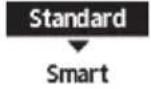 | |
| To set the tank sensor to Top or Center. • Selection of the tank sensor to top slow down the start of boiling up the tank and reduce power consumption. Please change this selection to “Center” when the hot water becomes insufficient. | Top |  | |
Menu Default Setting Setting Options / Display
| 2 System check | |||
| 2.1 > Energy monitor | |||
| Present or historical chart of energy consumption, generation or COP. | PresentSelect and retrieve | Total consumption (1year)0.0 kWh1year 112341567189101112 MonJan, 2015: 0.0 kWh Approx.Month Mode | |
| Historical chartSelect and retrieve | |||
| ·COP= Coeffi cient of Performance.·For historical chart, the period is selected from 1 day/1 week/1year.·Energy consumption (kWh) of heating, *1, *2 cooling, tank and total may be retrieved.·The total power consumption is an estimated value based on AC 230 V and may differ from value measured by precise equipment. | |||
| 2.2 > System information | |||
| Shows all system information in each area. | Actual system information of 10 items: Inlet / Outlet / Zone 1 / Zone 2 / Tank / Buffer tank / Solar / Pool / COMP frequency / Pump flowrateSelect and retrieve | System information 10:34am,Mon1. Inlet : 0°C2. Outlet : 0°C3. Zone 1 : 0°C4. Zone 2 : 0°CPage | |
| 2.3 > Error history | |||
| ·Refer to Troubleshooting for error codes.·The most recent error code is displayed at the top. | Select and retrieve | Error history 10:34am,Mon1. --2. --3. --4. --[--]Clear history | |
| 2.4 > Compressor | |||
| Shows the compressor performance. | Select and retrieve | Compressor 10:34am,Mon1. Current frequency : 0 Hz2. (OFF-ON) counter : 03. Total ON time : 0 h[→]Back | |
| 2.5 > Heater | |||
| Total hours of ON time for Room heater/Tank heater. | Select and retrieve | Heater 10:34am,MonTotal ON time: 0h: 0h[→]Back | |
| 3 Personal setup | |||
| 3.1 > Touch sound | |||
| Turns the operation sound ON/OFF. | ON | ONOFF | |
| 3.2 > LCD contrast | |||
| Sets the screen contrast. | 3 | LCD contrast 10:34am,MonLow High<→>Select [→]Confirm | |
| Menu Default Setting Setting Options / Display | |||
| 3.3 >Backlight | |||
| Sets the duration of screen backlight. | 1 min | Backlight 10:34am,MonOFF 5 mins15 secs 10 mins1 min | |
| Select [-]Confirm | |||
| 3.4 >Backlight intensity | |||
| Sets screen backlight brightness. | 4 | Backlight intensity 10:34am,MonDark Bright< [ ] | |
| Select [-]Confirm | |||
| 3.5 >Clock format | |||
| Sets the type of clock display. | 24h | Clock format 10:34am,Mon24ham/pmSelect [-]Confirm | |
| 3.6 >Date & Time | |||
| Sets the present date and time. | Year / Month / Day / Hour / Min | Date & Time 10:34am,MonYear/Month/Day Hour :Min2015/01/07 10:00 am | |
| Select [-]Confirm | |||
| 3.7 >Language | |||
| Sets the display language for the top screen.• For Greek, please refer to the English version. | ENGLISH / FRANÇAIS / DEUTSCH / ITALIANO / ESPAÑOL / DANISH / SWEDISH / NORWEGIAN / POLISH / CZECH / NEDERLANDS / TÜRKÇE / SUOMI / MAGYAR / SLOVENŠČINA / HRVATSKI / LIETUVIŲ | Language 10:34am,MonENGLISHFRANÇAISDEUTSCHITALIANO | |
| Select [-]Confirm | |||
| 3.8 >Unlock password | |||
| 4 digit password for all the settings. | 0000 | Unlock password 10:34am,Mon[IMAGE]Select [-]Confirm | |
| 4 Service contact | |||
| 4.1 >Contact 1 / Contact 2 | |||
| Preset contact number for installer. | Select and retrieve | Service setup 10:34am,MonContact 1Name : Bryan Adams☎ : 08812345678Select | |
| Menu Default Setting Setting Options / Display | ||
| 5 Installer setup System setup | ||
| 5.1 > Optional PCB connectivity | ||
| To connect to the external PCB required for servicing. | No | YesNo |
| ·If the external PCB is connected (optional), the system will have following additional functions:1 Buffer tank connection and control over its function and temperature.2 Control over 2 zones (including the swimming pool and the function to heat water in it).3 Solar function (the solar thermal panels connected to either the DHW (Domestic Hot Water) Tank or the Buffer Tan·DHW is not applicable for WH-ADC *models.4 External compressor switch.5 External error signal.6 SG ready control.7 Demand control.8 Heat-Cool SW | ||
| 5.2 > Zone & Sensor | ||
| To select the sensors and to select either 1 zone or 2 zone system. | Zone | Zone & Sensor 10:34am, Mon |
| ·After selecting 1 or 2 zone system, proceed to the selection of room or swimming pool.·If the swimming pool is selected, the temperature must be selected for △T temperature between 0°C ~ 10 °C. | Zone1 Zone system2 Zones systemSelect [-] Confirm | |
| Sensor | Zone & Sensor 10:34am, Mon | |
| * For room thermostat, there is a further selection of external or internal. | SensorWater temperatureRoom thermostatRoom thermistorSelect [-] Confirm | |
| 5.3 > Heater capacity | ||
| To reduce the heater power if unnecessary.*3 kW / 6 kW / 9kW* Options of kW vary depending on the model. | Heater capacity 10:34am, Mon3 kW6 kW*Select [-] Confirm | |
| 5.4 > Anti freezing | ||
| To activate or deactivate the water freeze prevention when the system is OFF | Yes | YesNo |
| Menu Default Setting Setting Options / Display | |||
| 5.5 > Buffer tank connection | |||
| To connect tank to the system and if selected YES, to set △T temperature.The optional PCB connectivity must be selected YES to enable the function.If the optional PCB connectivity is not selected, the function will not appear on the display. | No |  | |
| > Yes | |||
| 5 °C | Set △ for Buffer Tank | Buffer Tank 10:34am, Mon △T for Buffer TankRange: (0°C~10°C)Steps: ±1°C  Select [-] Confirm Select [-] Confirm | |
| 5.6 > Base pan heater | |||
| To select whether or not optional base pan heater is connected.* Type A - The base pan heater activates only during deice operation.* Type B -The base pan heater activates when outdoor ambient temperature is 5 °C or lower. | No |  | |
| > Yes | |||
| A | Set base pan heater type*. | Base pan heater type 10:34am, Mon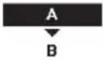 Select [-] Confirm Select [-] Confirm | |
| 5.7 > Alternative outdoor sensor | |||
| To select an alternative outdoor sensor. | No | 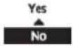 | |
| 5.8 > Bivalent connection | |||
| To select to enable or disable bivalent connection. | No | YesNo | |
| > Yes | |||
| To select either auto control pattern or SG ready input control pattern.* This selection only display to select when optional pcb connection set to Yes. | Auto | 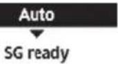 | |
Menu Default Setting Setting Options / Display
| To select a bivalent connection to allow an additional heat source such as a boiler to heat-up the buffer tank and domestic hot water tank when heatpump capacity is insufficient at low outdoor temperature. The bivalent feature can be set-up either in alternative mode (heatpump and boiler operate alternately), or in parallel mode (both heatpump and boiler operate simultaneously), or in advance parallel mode (heatpump operates and boiler turns on for buffer-tank and/or domestic hot water depending on the control pattern setting options). | >Yes>Auto | ||
| -5°C | Set outdoor temperature for turn ON Bivalent connection. | Bivalent connection 10:34am, MonTurn ON: Outdoor tempRange: (-15°C~35°C)Steps: ±1°C  Select [-/-] Confirm Select [-/-] Confirm | |
| Yes >After selecting the outdoor temperature | |||
| Control pattern | Bivalent connection 10:34am, MonControl patternAlternativeParallelAdvanced parallel*Select [-/-] Confirm | ||
| Alternative / Parallel / Advanced parallel | |||
| • Select advanced parallel for bivalent use of the tanks. | |||
| Control pattern >Alternative | |||
| OFF | Option to set external pump either ON or OFF during bivalent operation. Set to ON if system is simple bivalent connection. | Bivalent connection 10:34am, MonExternal pumpON▲OFF*Select [-/-] Confirm | |
| Control pattern >Advanced parallel | |||
| Heat Selection of the tank | Bivalent connection 10:34am, MonAdvanced parallelHeatDHWSelect [-/-] Confirm | ||
| • “Heat” implies Buffer Tank and “DHW” implies Domestic Hot Water Tank. | |||
| Control pattern >Advanced parallel >Heat Yes | |||
| • Buffer Tank is activated only after selecting “Yes”. | Bivalent connection 10:34am, MonAdvanced parallel: HeatYesNoSelect [-/-] Confirm | ||
| -8°C | Set the temperature threshold to start the bivalent heat source. | Bivalent connection 10:34am, MonHeat start: Target temp.Range: (-10°C~0°C)Steps: ±1°C  Select [-/-] Confirm Select [-/-] Confirm | |
| 0:30 | Delay timer to start the bivalent heat source (in hour and minutes). | Bivalent connection 10:34am, MonHeat start: Delay timeRange: (0:00~1:30)Steps: ±0:05  Select [-/-] Confirm Select [-/-] Confirm | |
| -2°C | Set the temperature threshold to stop the bivalent heat source. | Bivalent connection 10:34am, MonHeat stop: Target temp.Range: (-10°C~0°C)Steps: ±1°C  Select [-/-] Confirm Select [-/-] Confirm | |
| Menu Default Setting Setting Options / Display | |||
| 0:30 | Delay timer to stop the bivalent heat source (in hour and minutes). Bivalent connection 10:34am, Mon Heat stop: Delay time Range: (0:00~1:30) Steps: ±0:05 Select [-] Confirm | ||
| Control pattern >Advanced parallel >DHW Yes | |||
| · DHW Tank is activated only after selecting "Yes". | Bivalent connection 10:34am, Mon Advanced parallel: DHW Yes No Select [-] Confirm | ||
| 0:30 | Delay timer to start the bivalent heat source (in hour and minutes). Bivalent connection 10:34am, Mon DHW: Delay time Range: (0:30~1:30) Steps: ±0:05 Select [-] Confirm | ||
| SG ready input control for bivalent system follow below input condition. | >Yes >SG ready | ||
| OFF | Option to set external pump either ON or OFF during bivalent operation. Set to ON if system is simple bivalent connection. Bivalent connection 10:34am, Mon External pump ON OFF Select [-] Confirm | ||
| SG signal Operation pattern | |||
| Vcc-bit1 Vcc-bit2 | |||
| Open Open | Heat Pump OFF, Boiler OFF | ||
| Short Open | Heat Pump ON, Boiler OFF | ||
| Open Short | Heat Pump OFF, Boiler ON | ||
| Short Short | Heat Pump ON, Boiler ON | ||
| 5.9 >External SW | |||
| No | Yes No | ||
| 5.10 >Solar connection | |||
| · The optional PCB connectivity must be selected YES to enable the function. · If the optional PCB connectivity is not selected, the function will not appear on the display. · DHW is not applicable for WH-ADC *models. | No | Yes No | |
| >Yes | |||
| Buffer tank Selection of the tank | Solar connection 10:34am, Mon Buffer tank DHW tank Select [-] Confirm | ||
| >Yes >After selecting the tank | |||
| 10 °C | Set △T ON temperature Solar connection 10:34am, Mon △T Turn ON Range: (6°C~15°C) Steps: ±1°C Select [-] Confirm | ||
Menu Default Setting Setting Options / Display
| >Yes >After selecting the tank >TON temperature | |||
| 5°C | Set ΔT OFFtemperature | Solar connection 10:34am, MonΔT Turn OFFRange: (2°C~9°C)Steps: ±1°C  Select [-J] Confirm Select [-J] Confirm | |
| >Yes >After selecting the tank >TON temperature TOFF temperature | |||
| 5°C | Set Antifreeze temperature | Solar connection 10:34am, MonAnti freezeRange: (-20°C~10°C)Steps: ±1°C  Select [-J] Confirm Select [-J] Confirm | |
| >Yes >After selecting the tank >TON temperature TOFF temperature> After setting the antifreeze temperature | |||
| 80°C Set Hi limit | 80°C Set Hi limit | Solar connection 10:34am, MonHi limitRange: (70°C~90°C)Steps: ±5°C  Select [-J] Confirm Select [-J] Confirm | |
| 5.11 >External error signal | |||
| No | YesNo | ||
| 5.12 >Demand control | |||
| No | YesNo | ||
| 5.13 >SG ready | |||
| No | YesNo | ||
| >Yes | |||
| 120% | Capacity (1) & (2)of DHW (in %),Heat (in %) andCool (in °C) | SG ready 10:34am, MonCapacity [1-0]: DHWRange: (50%~150%) Steps: ±5% 120%Select [-J] Confirm | |
| 5.14 >External compressor SW | |||
| No | YesNo | ||
| 5.15 >Circulation liquid | |||
| To select whether to circulate water or glycol in the system. | Water | Circulation liquid 10:34am, MonWaterGlycolSelect [-J] Confirm | |
| Menu Default Setting Setting Options / Display | |||
| 5.16 > Heat-Cool SW | |||
| No | YesNo | ||
| 5.17 > Force heater | |||
| To turn on Force heater either manually (by default) or automatically. | Manual | Force heater 10:34am,MonAutoManual | |
| Select [-]Confirm | |||
| 5.18 > Defrost signal | |||
| To turn on defrost signal to stop fan coil during defrost operation.(If defrost signal set to yes, bivalent function will not available to use) | No | YesNo | |
| 5.19 > Pump flowrate | |||
| To set variable flow pump control or fi x pump duty control. | ΔT | ΔTMax. Duty | |
| 6 Installer setup Operation setup | |||
| To access to the four major functions or modes. | 4 main modesHeat / *1, *2 Cool / *1, *2 Auto / Tank | Operation setup 10:34am,MonHeatCoolAutoTankSelect [-]Confirm | |
| 6.1 > Heat | |||
| To set various water & ambient temperatures for heating. | Water temp. for heating ON /Outdoor temp. for heating OFF /ΔT for heating ON /Heater ON/OFF | Operation setup 10:34am,MonHeatWater temp. for heating ONOutdoor temp. for heating OFFΔT for heating ONSelect [-]Confirm | |
| > Water temp. for heating ON | |||
| Compensation curve | Heating ON temperatures in compensation curve or direct input. | Operation setup 10:34am,MonHeat ON: Water temp.Compensation curveDirectSelect [-]Confirm | |
*1 The system is locked to operate without COOL mode. It can be unlocked only by authorised installers or our authorised service partners.
*2 Only displayed when COOL mode is unlocked (This means when COOL mode is available).
Menu Default Setting Setting Options / Display
Water temp. for heating ON > Compensation curve
| X axis: -5 °C, 15 °CY axis: 55 °C, 35 °C | Input the 4 temperature points (2 on horizontal X axis, 2 on vertical Y axis). | Heat ON: Water temp.:Zone1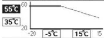 ←→ Select [←]Confirm ←→ Select [←]Confirm |
Heat ON: Water temp.:Zone1
Select
[←] Confirm
- Temperature range: X axis: -20 °C \~ 15 °C, Y axis: See below
• Temperature range for the Y axis input: - WH-UD model: 20 °C \~ 60 °C
- WH-UH model & Back up heater is enabled: 25 °C \~ 65 °C
- WH-UH model & Back up heater is disabled: 35 °C \~ 65 °C
- WH-UX model: 20 °C \~ 60 °C
- If 2 zone system is selected, the 4 temperature points must also be input for Zone 2.
- "Zone 1" and "Zone 2" will not appear on the display if only 1 zone system.
Water temp. for heating ON > Direct
| 35 °C | Temperature for heating ON | Operation setup 10:34am,Mon | |
| Heat ON: Water temp.:Zone2 | |||
| Range: (20°C~60°C)Steps: ±1°C | 35°C | ||
| Select [-] Confirm | |||
Operation setup 10:34am, Mon
Heat ON: Water temp.:Zone2
| Range: (20°C~60°C)Steps: ±1°C | 35 °C | |
| Select | [-] Confirm | |
- Min. \~ Max. range is conditional as follows:
- WH-UD model: 20 °C \~ 60 °C
- WH-UH model & Back up heater is enabled: 25 °C \~ 65 °C
- WH-UH model & Back up heater is disabled: 35 °C \~ 65 °C
- WH-UX model: 20 °C \~ 60 °C
- If 2 zone system is selected, temperature set point must input for Zone 2.
- "Zone 1" and "Zone 2" will not appear on the display if only 1 zone system.
Outdoor temp. for heating OFF
| 24 °C | Temperature for heating OFF | Operation setup 10:34am, Mon | |
| Heat OFF: Outdoor temp. | |||
| Range: (5°C~35°C)Steps: ±1°C | 24 °C | ||
| Select [→] Confirm | |||
Operation setup 10:34am, Mon
Heat OFF: Outdoor temp.
| Range: (5°C~35°C) |
| Steps: ±1°C |
Select
[→] Confirm
4 for heating ON
| 5°C | Set △T for heating ON.* This setting will not available to set when pump flowrate set to Max. duty. | Operation setup 10:34am, Mon | |
| Heat ON: ΔT | |||
| Range: (1°C~15°C)Steps: ±1°C | 5°C | ||
| Select [←] Confirm | |||
Operation setup 10:34am, Mon
| Heat ON: T | |
| Range: (1°C~15°C) | |
| Steps: ± 1^ | 5 °C |
Select
[←]Confirm
Heater ON/OFF
| > Heater ON/OFF >Outdoor temp. for heater ON | ||
| 0 °C | Temperature for heater ON | Operation setup 10:34am,Mon |
| Heater ON: Outdoor temp. | ||
| Range: (-20°C~15°C)Steps: ±1°C | ||
| Select [-]Confirm | ||
Select
[→]Confirm
Menu Default Setting Setting Options / Display
| >Heater ON/OFF >Delay time for heater ON | |||
| 0:30 min | Delay time for heater to turn on | Operation setup 10:34am, Mon | |
Heater ON: Delay timeRange: (0:10~1:00)Steps: ±0:10  Select [-] Confirm Select [-] Confirm | |||
| >Heater ON/OFF >Water temperature for heater ON | |||
| -4 °C | Setting of water temperature to turn on from water set temperature. | Operation setup 10:34am, MonHeater ON: ΔT of target Temp.Range: (-10°C~-2°C)Steps: ±1°C  Select [-] Confirm Select [-] Confirm | |
| >Heater ON/OFF >Water temperature for heater OFF | |||
| -2 °C | Setting of water temperature to turn off from water set temperature. | Operation setup 10:34am, MonHeater OFF: ΔT of target Temp.Range: (-8°C~0°C)Steps: ±1°C  Select [-] Confirm Select [-] Confirm | |
| 6.2 >*1, *2 Cool | |||
| To set various water & ambient temperatures for cooling. | Water temperatures for cooling ON and △T for cooling ON. | Operation setup 10:34am, MonCoolWater temp. for cooling ON△T for cooling ONSelect [-] Confirm | |
| >Water temp. for cooling ON | |||
| Compensation curve | Cooling ON temperatures in compensation curve or direct input. | Operation setup 10:34am, MonCool ON: Water temp.Compensation curveDirectSelect [-] Confirm | |
| >Water temp. for cooling ON >Compensation curve | |||
| X axis: 20 °C, 30 °CY axis: 15 °C, 10 °C | Input the 4 temperature points (2 on horizontal X axis, 2 on vertical Y axis) | Cool ON: Water temp: Zone115°C2010°C515 20°C 30°C 30Select [-] Confirm | |
| • If 2 zone system is selected, the 4 temperature points must also be input for Zone 2.• “Zone 1” and “Zone 2” will not appear on the display if only 1 zone system. | |||
*1 The system is locked to operate without COOL mode. It can be unlocked only by authorised installers or our authorised service partners.
*2 Only displayed when COOL mode is unlocked (This means when COOL mode is available).
Menu Default Setting Setting Options / Display
| >Water temp. for cooling ON >Direct | |||
| 10°C | Set temperature for Cooling ON | Operation setup 10:34am, MonCool ON: Water temp.: Zone2Range: (5°C~20°C)Steps: ±1°C  Select [-] Confirm Select [-] Confirm | |
| • If 2 zone system is selected, temperature set point must input for Zone 2.• “Zone 1” and “Zone 2” will not appear on the display if only 1 zone system. | |||
| >ΔT for cooling ON | |||
| 5°C | Set ΔT for cooling ON* This setting will not available to set when pump flowrate set to Max. duty. | Operation setup 10:34am, MonCool ON: ΔTRange: (1°C~15°C)Steps: ±1°C  Select [-] Confirm Select [-] Confirm | |
| 6.3 >*1, *2 Auto | |||
| Automatic switch from Heat to Cool or Cool to Heat. | Outdoor temperatures for switching from Heat to Cool or Cool to Heat.Outdoor temp. for (Heat to Cool) / Outdoor temp. for (Cool to Heat) | Operation setup 10:34am, MonAutoOutdoor temp. for (Heat to Cool)Outdoor temp. for (Cool to Heat)Select [-] Confirm | |
| >Outdoor temp. for (Heat to Cool) | |||
| 15°C | Set outdoor temperature for switching from Heat to Cool. | Operation setup 10:34am, MonAuto: Outdoor temp.(Heat to Cool)Range: (11°C~25°C)Steps: ±1°C  Select [-] Confirm Select [-] Confirm | |
| >Outdoor temp. for (Cool to Heat) | |||
| 10°C | Set outdoor temperature for switching from Cool to Heat. | Operation setup 10:34am, MonAuto: Outdoor temp.(Cool to Heat)Range: (5°C~14°C)Steps: ±1°C  Select [-] Confirm Select [-] Confirm | |
| 6.4 >Tank | |||
| Setting functions for the tank. | Floor operation time (max) /Tank heat up time (max) /Tank re-heat temp. /Sterilization | Operation setup 10:34am, MonTankFloor operation time (max)Tank heat up time (max)Tank re-heat temp.Select [-] Confirm | |
| • The display will show 3 functions at a time. | |||
| >Floor operation time (max) | |||
| 8:00 | Maximum time for floor operation (in hours and minutes) | Operation setup 10:34am, MonTank: Floor ope. time (max)Range: (0:30~10:00)Steps: ±0:30 Select [-] Confirm | |
*1 The system is locked to operate without COOL mode. It can be unlocked only by authorised installers or our authorised service partners.
*2 Only displayed when COOL mode is unlocked (This means when COOL mode is available).
Menu Default Setting Setting Options / Display
| > Tank heat up time (max) | |||
| 1:00 | Maximum time for heating the tank (in hours and minutes) | Operation setup 10:34am, MonTank: Heat up time (max)Range: (0:05~4:00)Steps: ±0:05  Select [--]-] Confirm Select [--]-] Confirm | |
| > Tank re-heat temp. | |||
| -8 °C | Set temperature to perform reboil of tank water. | Operation setup 10:34am, MonTank: Re-heat temp.Range: (-12°C~-2°C)Steps: ±1°C  Select [--]-] Confirm Select [--]-] Confirm | |
| > Sterilization | |||
| Monday | Sterilization may be set for 1 or more days of the week.Sun / Mon / Tue / Wed / Thu / Fri / Sat | Operation setup 10:34am, MonSterilization: DaySun Mon Tue Wed Thu  Day - √ - - - Day - √ - - - | |
| > Sterilization: Time | |||
| 12:00 | Time of the selected day(s) of the week to sterilize the tank0:00 ~ 23:59 | Operation setup 10:34am, MorSterilization: Time12:00 p  Select [--]-] Confirm Select [--]-] Confirm | |
| > Sterilization: Boiling temp. | |||
| 65 °C | Set boiling temperatures for sterilize the tank. | Operation setup 10:34am, MorSterilization: Boiling temp.Range: (55°C~65°C)Steps: ±1°C  Select [--]-] Confirm Select [--]-] Confirm | |
| > Sterilization: Ope. time (max) | |||
| 0:10 | Set sterilizing time (in hours and minutes) | Operation setup 10:34am, MonSterilization: Ope. time (max)Range: (0:05~1:00)Steps: ±0:05  Select [--]-] Confirm Select [--]-] Confirm | |
7 Installer setup Service setup
| 7.1 > Pump maximum speed | ||
| To set the maximum speed of the pump. | Setting the flow rate, max. duty and operation ON/OFF of the pump. | Service setup 10:34am, Mon |
| Flow rate Max. Duty Operation | ||
0.0 L/min 0xFE  | ||
| Select | ||
| Menu Default Setting Setting Options / Display | ||
| 7.2 > Pump down | ||
| To set the pump down operation. | Pump down operationON | 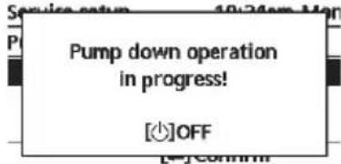 |
| 7.3 > Dry concrete | ||
| To dry the concrete (floor, walls, etc.) during construction.Do not use this menu for any other purposes and in period other than during construction | Edit to set the temperature of dry concrete.ON / Edit | Service setup 10:34am,MonDry concrete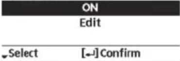 |
| > Edit | ||
| Stages: 1Temperature: 25 °C | Heating temperature for drying the concrete.Select the desired stages: 1 ~ 10,range: 1 ~ 99 | |
| > ON | ||
| Confir rm the setting temperatures of dry concrete for each stage. | 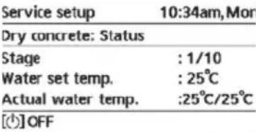 | |
| 7.4 > Service contact | ||
| To set up to 2 contact names and numbers for the User. | Service engineer's name and contact number.Contact 1 / Contact 2 | Service setup 10:34am,MonService contact: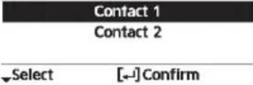 |
| > Contact 1 / Contact 2 | ||
| Contact name or number.Name / phone icon | Service contact 10:34am,MonContact 1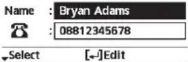 | |
| Input name and numberContact name: alphabet a ~ z.Contact number: 1 ~ 9 | Contact-1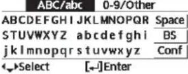 Number: Number: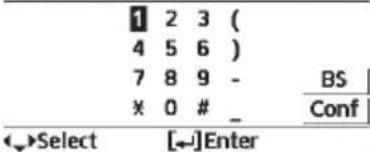 | |
To ensure optimal performance of the system, cleaning has to be carried out at regular intervals. Consult an authorised dealer.
- Disconnect the power supply before cleaning.
- Do not use benzine, thinner or scouring powder.
- Use only soap ( pH7) or neutral household detergent.
- Do not use water hotter than 40^ .
Indoor unit
- Do not splash water directly. Wipe the unit gently with a soft dry cloth.
natural_image
Pure schematic diagram of a vertical control panel with no text, numbers, or symbols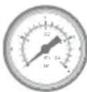
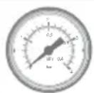
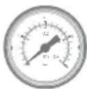
Water pressure gauge

- Do not press or hit the glass cover using hard and sharp objects. Failure to do so may cause damage to the unit.
- Ensure that the water pressure is between 0.05 and 0.3MPa (0.1MPa = 1 bar).
- In case the water pressure is out of the above range, consult an authorised dealer.

Water fi Iter
- Clean the water fi Iter at least once a year. Failure to do so may cause the fi Iter to clog up, which may lead to system breakdown. Consult an authorised dealer.
- Please also remove dust on the magnet.
Water Filter Set
Outdoor unit
- Do not obstruct the air inlet and outlet vents. Failure to do so may result in low performance or system breakdown. Remove any obstruction to assure the ventilation.
- When it snows, clean and remove snow around the outdoor unit to prevent the air inlet and outlet vents from being covered with snow.
For extended non-use
- The water inside the Sanitary Water Tank should be drained.
- Disconnect the power supply.
Non serviceable criteria
Disconnect the power supply
then please consult an authorised dealer under the following conditions:
- Abnormal noise during operation.
- Water/foreign particles have entered the Remote Controller.
• Water leaks from the indoor unit. - Circuit breaker switches off frequently.
- Power cord becomes excessively warm.
MAINTENANCE
User
- In order to ensure optimal performance of the units, user may inspect and clear any obstruction on the air inlet and outlet vents of the outdoor unit.
- Users should not try to service or replace parts of the unit.
- Contact authorised dealer for scheduled inspection.
Dealer
- In order to ensure safety and optimal performance of the units, seasonal inspections on the units, functional check of RCCB/ELCB, field wiring and piping have to be carried out at regular intervals by authorised dealer.
- Specific to the Sanitary Water Tank, it is important to service the Water Filter Set periodically.
Troubleshooting
The following symptoms do not indicate malfunction.
| Symptom Cause | |
| Water flowing sound during operation. | • Refrigerant flow inside the unit. |
| Operation is delayed a few minutes after restarting. | • The delay is a protection for the compressor. |
| Outdoor unit emits water/steam. | • Condensation or evaporation occurring in the pipes. |
| Steam comes out of the outdoor unit in the heating mode. | • It is caused by defrost operation in the heat exchanger. |
| Outdoor unit does not operate. | • It is caused by the protection control of the system when outdoor temperature is out of the operating range. |
| System operation switches off. | • It is caused by the protection control of the system. When the water inlet temperature is lower than 10 °C, the compressor stops and the backup heater power turns on. |
| System is hard to heat up. | • When the panel and the floor are heated simultaneously, warm water temperature may decrease, which may reduce the heating ability of the system.• When the outdoor air temperature is low, the system may need longer time to heat up.• Discharge outlet or intake inlet in the outdoor unit is blocked by some obstacle, such as a pile of snow.• When the preset water outlet temperature is low, the system may need longer time to heat up. |
| System does not heat up instantly. | • System will take some time to heat up the water if it starts to operate at cold water temperature. |
| Backup heater is automatically turned ON when it is disabled. | • It is caused by the protection control of the indoor unit heat exchanger. |
| Operation starts automatically when the timer is not set. | • Sterilization timer has been set. |
| Loud refrigerant noise continues for several minutes. | • It is caused by protection control during deice operation at outdoor ambient temperature lower than -10 °C. |
| *1,*2 COOL mode is unavailable. | • System has locked to operate in HEAT mode only. |
Check the following before calling for servicing.
| Symptom Check | |
| Operation in HEAT/^*1 . *2 COOL mode is not working effi ciently. | Set the temperature correctly.Close the panel heater/cooler valve.Clear any obstruction in the air inlet and air outlet vents of the outdoor unit. |
| Noisy during operation. | Outdoor unit or indoor unit has been installed at an incline.Close the cover properly. |
| System does not work. • Circuit breaker | has tripped/activated. |
| Operation LED is not lit or nothing is displayed on the Remote Controller. | Power supply is working correctly, or a power failure has occurred. |
*1 The system is locked to operate without COOL mode. It can be unlocked only by authorised installers or our authorised service partners.
*2 Only displayed when COOL mode is unlocked (This means when COOL mode is available).
Below is a list of error codes that may appear on the display when there is some trouble with the system setting or operation.
When the display shows an error code as indicated below, contact the number registered in the Remote Controller or a nearest authorised installer.
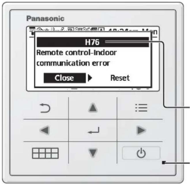
All switches are disabled except ◀ and .
Error number
Blinking
| Error No. | Error explanation |
| H12 | Capacity mismatch |
| H15 | Compressor sensor error |
| H20 | Pump error |
| H23 | Refrigerant sensor error |
| H27 | Service valve error |
| H28 | Solar sensor error |
| H31 | Pool sensor error |
| H36 | Buffer tank sensor error |
| H38 | Brand mismatch error |
| H42 | Low pressure protection |
| H43 | Zone 1 sensor error |
| H44 | Zone 2 sensor error |
| H62 | Water flow error |
| H63 | Low pressure sensor error |
| H64 | High pressure sensor error |
| H65 | Deice water circulation error |
| H67 | External thermistor 1 error |
| H68 | External thermistor 2 error |
| H70 | Back-up heater OLP error |
| H72 | Tank sensor error |
| H74 | PCB communication error |
| H75 | Low water temp protection |
| H76 | RC-Indoor communication error |
| H90 | Indoor-Outdoor communication error |
| H91 | Tank heater OLP error |
| H95 | Voltage connection error |
| H98 | High pressure protection |
| H99 | Indoor freeze prevention |
| Error No. | Error explanation |
| F12 | Pressure switch activated |
| F14 | Poor compressor rotation |
| F15 | Fan motor lock error |
| F16 | Current protection |
| F20 | Compressor overload protection |
| F22 | Transistor module overload protection |
| F23 | DC peak |
| F24 | Refrigerant cycle error |
| F25 | *1, *2 Cool / heat cycle error |
| F27 | Pressure switch error |
| F29 | Low discharge super heat |
| F30 | Water outlet sensor 2 error |
| F32 | Internal thermostat error |
| F36 | Outdoor ambient sensor error |
| F37 | Water inlet sensor error |
| F40 | Outdoor discharge sensor error |
| F41 | Power factor correction error |
| F42 | Outdoor heat exchanger sensor error |
| F43 | Outdoor defrost sensor error |
| F45 | Water outlet sensor error |
| F46 | Current transformer disconnection |
| F48 | Evaporator outlet sensor error |
| F49 | Bypass outlet sensor error |
| F95 | *1, *2 Cooling high pressure error |
* Some error code may not be applicable to your model. Consult authorised dealer for clarification.
*1 The system is locked to operate without COOL mode. It can be unlocked only by authorised installers or our authorised service partners.
*2 Only displayed when COOL mode is unlocked (This means when COOL mode is available).
Information when connect to Network Adaptor (Optional Accessories Part)

WARNING
Before use, check the safety around the Air-to-Water system. Confirm human and living objects at surrounding before operation.
Incorrect operation due to failure to follow instructions may cause harm and damage.

Confir rm the below before operation (inside premises)
- Timer setting condition. Unpredictable on/off operation may cause serious injury or damage to human and living objects.
Confir rm the below before and during operation (outside from premises)
- If is known someone in the premises, notify the person from outside of new operation setting prior executing. This is to avoid sudden shock to the person and any serious health breakdown duly from operation changed.
- Please do not use this appliance when infant, physical disability person or elderly who unable to operate the appliance by themselves in the premises.
- Check the setting and operation status frequently.
- Stop the operation when error code is displayed and consult an authorised dealer or specialist.
Please confi rm before use
- The system may not usable when communication condition is bad. Please check "Operation Status" from the application display after operation. The following condition may happen in the remote operation.
- Cannot operate, operation time is not reflected.
- Air-to-Water operation is not reflected when operation is set outside of premises.
- It is recommended to lock screen the smart phone device to prevent miss-operation.
- Do not use other remote control, communication and operation device not specified by an authorised dealer or specialist.
- Use under the agreement of "Terms of Service" and "Handling of Personal Information" of Panasonic Smart Application.
- For extended non-use of Panasonic Smart Application, disconnect the network adaptor from the device.
Information for Users on Collection and Disposal of Old Equipment
This symbol on the products, packaging, and/or accompanying documents means that used electrical and electronic products must not be mixed with general household waste.
For proper treatment, recovery and recycling of old products, please take them to applicable collection points in accordance with your national legislation.
By disposing of these products correctly, you will help to save valuable resources and prevent any potential negative effects on human health and the environment which could otherwise arise from inappropriate waste handling.
For more information about collection and recycling of old products, please contact your local municipality, your waste disposal service or the point of sale where you purchased the items.
Penalties may be applicable for incorrect disposal of this waste, in accordance with national legislation.
For business users in the European Union
If you wish to discard electrical and electronic equipment, please contact your dealer or supplier for further information.
[Information on Disposal in other Countries outside the European Union]
These symbols are only valid in the European Union. If you wish to discard these items, please contact your local authorities or dealer and ask for the correct method of disposal.
 WARNING WARNING | This symbol shows that this equipment uses a fl ammable refrigerant. If the refrigerant is leaked, together with an external ignition source, there is a possibility of ignition. |  | This symbol shows that the Operation Instructions should be read carefully. |
 | This symbol shows that a service personnel should be handling this equipment with reference to the Installation Instructions. |  | This symbol shows that there is information included in the Operation Instructions and/or Installation Instructions. |
natural_image
Hand pointing at a grid with directional arrows (no text or symbols)
No use
bolígrafos

natural_image
Hand holding a pen writing on a grid with arrows indicating direction (no text or symbols present)Pantalla
-
8:00am ON 40°C
-
12:00pm ON 24/28°C 40°C
-
1:00pm ON 12/10°C
natural_image
Hand pointing at a grid with directional arrows (no text or symbols)
Senza penna

natural_image
Hand holding a pen writing on a grid with directional arrows (no text or symbols)Display
natural_image
Pure schematic diagram of a vertical control panel with no text, numbers, or symbols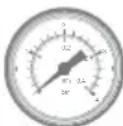
Filtro
Unità esterna
Pijltjestoetsen
natural_image
Hand pointing at a grid with directional arrows (no text or symbols)
Gebruik geen pen

natural_image
Hand holding a pen writing on a grid with arrows indicating direction (no text or symbols present)Forceren warmtapwater

natural_image
Simple line drawing of a refrigerator with a digital display and control panel (no text or symbols)Warmtapwatertank
Waterdrukmeter

Waterfi Iterset
Buitenunit
Przyciski kursora
Wybór pozycji.
natural_image
Illustration of a hand pointing at a grid with directional arrows (no text or symbols)natural_image
Hand holding a pen writing on a grid with arrows indicating direction (no text or symbols present)Wyświetlacz
① Wybór trybu
flowchart
graph TD
    A["GRZANIE"] --> B["*1,*2 AUTO"]
    B --> C["GRZANIE + ZBIORNIK"]
    C --> D["*1,*2 AUTO + ZBIORNIK"]
    D --> E["*1,*2 CHŁODZ."]
    E --> F["*1,*2 CHŁODZ. + ZBIORNIK"]
    F --> G["ZBIORNIK"]
    G --> H["*1,*2 CHŁODZ."]
    H --> I["*1,*2 CHŁODZ. + ZBIORNIK"]
    I --> J["*1,*2 CHŁODZ. + ZBIORNIK"]
    J --> K["GRZANIE + ZBIORNIK"]
    K --> L["*1,*2 CHŁODZ."]
    L --> M["*1,*2 CHŁODZ. + ZBIORNIK"]
    M --> N["GRZANIE + ZBIORNIK"]
    N --> O["*1,*2 CHŁODZ."]
    O --> P["*1,*2 CHŁODZ. + ZBIORNIK"]
    P --> Q["GRZANIE + ZBIORNIK"]
    Q --> R["*1,*2 CHŁODZ."]
    R --> S["*1,*2 CHŁODZ. + ZBIORNIK"]
    S --> T["GRZANIE + ZBIORNIK"]
    T --> U["*1,*2 CHŁODZ."]
    U --> V["*1,*2 CHŁODZ. + ZBIORNIK"]
    V --> W["GRZANIE + ZBIORNIK"]
    W --> X["*1,*2 CHŁODZ."]
    X --> Y["*1,*2 CHŁODZ. + ZBIORNIK"]
    Y --> Z["GRZANIE + ZBIORNIK"]
    Z --> AA["*1,*2 CHŁODZ."]
    AA --> AB["*1,*2 CHŁODZ. + ZBIORNIK"]
    AB --> AC["GRZANIE + ZBIORNIK"]
    AC --> AD["*1,*2 CHŁODZ."]
    AD --> AE["*1,*2 CHŁODZ. + ZBIORNIK"]
    AE --> AF["GRZANIE + ZBIORNIK"]
    AF --> AG["*1,*2 CHŁODZ."]
    AG --> AH["*1,*2 CHŁODZ. + ZBIORNIK"]
    AH --> AI["GRZANIE + ZBIORNIK"]
    AI --> AJ["*1,*2 CHŁODZ."]
    AJ --> AK["*1,*2 CHŁODZ. + ZBIORNIK"]
    AK --> AL["GRZANIE + ZBIORNIK"]
    AL --> AM["*1,*2 CHŁODZ."]
    AM --> AN["*1,*2 CHŁODZ. + ZBIORNIK"]
    AN --> AO["GRZANIE + ZBIORNIK"]
    AO --> AP["*1,*2 CHŁODZ."]
    AP --> AQ["*1,*2 CHŁODZ. + ZBIORNIK"]
    AQ --> AR["GRZANIE + ZBIORNIK"]
    AR --> AS["*1,*2 CHŁODZ."]
    AS --> AT["*1,*2 CHŁODZ. + ZBIORNIK"]
    AT --> AU["GRZANIE + ZBIORNIK"]
    AU --> AV["*1,*2 CHŁODZ."]
    AV --> AW["*1,*2 CHŁODZ. + ZBIORNIK"]
    AW --> AX["GRZANIE + ZBIORNIK"]
    AX --> AY["*1,*2 CHŁODZ."]
    AY --> AZ["*1,*2 CHŁODZ. + ZBIORNIK"]
    AZ --> BA["GRZANIE + ZBIORNIK"]
    BA --> BB["*1,*2 CHŁODZ."]
    BB --> BC["*1,*2 CHŁODZ. + ZBIORNIK"]
    BC --> BD["GRZANIE + ZBIORNIK"]
    BD --> BE["*1,*2 CHŁODZ."]
    BE --> BF["*1,*2 CHŁODZ. + ZBIORNIK"]
    BF --> BG["GRZANIE + ZBIORNIK"]
    BG --> BH["*1,*2 CHŁODZ."]
    BH --> BI["*1,*2 CHŁODZ. + ZBIORNIK"]
    BI --> BJ["GRZANIE + ZBIORNIK"]
    BJ --> BK["*1,*2 CHŁODZ."]
    BK --> BL["*1,*2 CHŁODZ. + ZBIORNIK"]
    BL --> BM["GRZANIE + ZBIORNIK"]
    BM --> BN["*1,*2 CHŁODZ."]
    BN --> BO["*1,*2 CHŁODZ. + ZBIORNIK"]
    BO --> BP["GRZANIE + ZBIORNIK"]
    BP --> BQ["*1,*2 CHŁODZ."]
    BQ --> BR["*1,*2 CHŁODZ. + ZBIORNIK"]
    BR --> BS["GRZANIE + ZBIORNIK"]
    BS --> BT["*1,*2 CHŁODZ."]
    BT --> BU["*1,*2 CHŁODZ. + ZBIORNIK"]
    BU --> BV["GRZANIE + ZBIORNIK"]
    BV --> BW["*1,*2 CHŁODZ."]
    BW --> BX["*1,*2 CHŁODZ. + ZBIORNIK"]
    BX --> BY["GRZANIE + ZBIORNIK"]
    BY --> BZ["*1,*2 CHŁODZ."]
    BZ --> CA["*1,*2 CHŁODZ. + ZBIORNIK"]
    CA --> CB["*1,*2 CHŁODZ. + ZBIORNIK"]
    CB --> CC["GRZANIE + ZBIORNIK"]
    CC --> CD["*1,*2 CHŁODZ."]
    CD --> CE["*1,*2 CHŁODZ. + ZBIORNIK"]
    CE --> CF["*1,*2 CHŁODZ. + ZBIORNIK"]
    CF --> CG["GRZANIE + ZBIORNIK"]
    CG --> CH["*1,*2 CHŁODZ."]
    CH --> CI["*1,*2 CHŁODZ. + ZBIORNIK"]
    CI --> CJ["*1,*2 CHŁODZ. + ZBIORNIK"]
    CJ --> CK["GRZANIE + ZBIORNIK"]
    CK --> CL["*1,*2 CHŁODZ."]
    CL --> CD
    CD --> CD
② Ikony działania
-
8:00am Wt 40°C
-
12:00pm Wt 24/28°C 40°C
-
1:00pm Wt 12/10°C
natural_image
Pure schematic diagram of a vertical container with internal components and dashed lines indicating flow or layout (no text or symbols)natural_image
Cross-sectional diagram of an electrical cabinet or enclosure with internal components and wiring (no text or labels visible)natural_image
Hand pointing at a grid with directional arrows (no text or symbols)
Χωρίς στυλό
natural_image
Hand holding a pen writing on a grid with directional arrows (no text or symbols)| Weekly timer 10:34am, Mon | |||||
| Sun Mon | Tue Wed | Thu Fri | Sat | ||
| 1. 8:00am ON | 40^ | ||||
| 2. 12:00pm ON | 24/28^ | 40^ | |||
| 3. 1:00pm ON | 12/10^ | ||||
| Day Pattern [+]Edit | |||||
Kurzorová tlačítka
Výběr položky.

Vstup
natural_image
Hand pointing at a grid with directional arrows (no text or symbols)
Ne perem

natural_image
Hand holding a pen writing on a grid with directional arrows (no text or symbols)natural_image
Pure schematic diagram of a vertical container with internal components and dashed lines indicating flow or layout (no text or symbols)natural_image
Cross-sectional diagram of an industrial equipment or machinery assembly (no visible text or labels)4 Contact maintenance ....209
4.1 Contact 1 / Contact 2
natural_image
Hand pointing at a grid with directional arrows (no text or symbols)
Sans stylo

natural_image
Hand holding a pen writing on a grid with arrows indicating direction (no text or symbols present)Affi chage
① Sélection du mode

natural_image
Pure diagram of a vertical container with a control panel and dashed lines indicating internal structure (no text or symbols)
natural_image
Cross-sectional diagram of an electrical cabinet or enclosure with internal components and wiring (no text or labels visible)natural_image
Hand pointing at a grid with directional arrows (no text or symbols)
Kein Stift

natural_image
Hand holding a pen writing on a grid with directional arrows (no text or symbols)Display
natural_image
Pure schematic diagram of a vertical container with internal components and dashed lines indicating flow or layout (no text or symbols)Warmwasserspeicher
natural_image
Illustration of a hand pointing at a grid with directional arrows (no text or symbols)
Kalem yok
