KS 54 SP - Saw METABO - Free user manual and instructions
Find the device manual for free KS 54 SP METABO in PDF.
| Feature | Details |
|---|---|
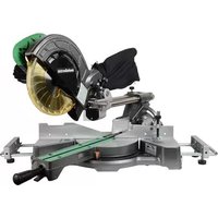
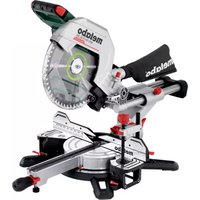
| Type of saw | Circular saw |
| Power | 1600 W |
| Blade diameter | 190 mm |
| Cutting depth | 65 mm at 90° |
| No-load speed | 5000 rpm |
| Weight | 4.5 kg |
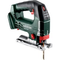
| Usage | Cutting wood, panels, composite materials |
| Protection system | Blade guard cover |
| Maintenance | Regular blade check and cleaning |
| Included accessories | Saw blade, service key |
| Safety standards | Compliant with CE standards |
| Warranty | 2 years |
Frequently Asked Questions - KS 54 SP METABO
User questions about KS 54 SP METABO
0 question about this device. Answer the ones you know or ask your own.
Ask a new question about this device
Download the instructions for your Saw in PDF format for free! Find your manual KS 54 SP - METABO and take your electronic device back in hand. On this page are published all the documents necessary for the use of your device. KS 54 SP by METABO.
USER MANUAL KS 54 SP METABO
<= 5 mm (<= 3/16 ") min
7.2 Setting depth of cut
7.3 Slanting saw disc for diagonal cuts
7.4 Correcting angle of saw disc
7.5 Preselecting the speed
8.1 Switching on and off
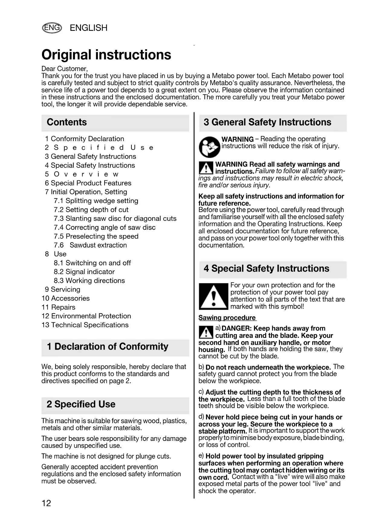
9 Servicing 10 Accessories 11 Repairs 12 Environmental Protection 13 Technical Specifications We, being solely responsible, hereby declare that this product conforms to the standards and directives specified on page 2. This machine is suitable for sawing wood, plastics, metals and other similar materials. The user bears sole responsibility for any damage caused by unspecified use. The machine is not designed for plunge cuts. Generally accepted accident prevention regulations and the enclosed safety information must be observed. WARNING – Reading the operating instructions will reduce the risk of injury. WARNING Read all safety warnings and instructions. Failure to follow all safety warn- ings and instructions may result in electric shock, fire and/or serious injury. Keep all safety instructions and information for future reference. Before using the power tool, carefully read through and familiarise yourself with all the enclosed safety information and the Operating Instructions. Keep all enclosed documentation for future reference, and pass on your power tool only together with this documentation. For your own protection and for the protection of your power tool pay attention to all parts of the text that are marked with this symbol! Sawing procedure
DANGER: Keep hands away from
cutting area and the blade. Keep your second hand on auxiliary handle, or motor housing. If both hands are holding the saw, they cannot be cut by the blade.
Do not reach underneath the workpiece. The safety guard cannot protect you from the blade below the workpiece.
Adjust the cutting depth to the thickness of the workpiece. Less than a full tooth of the blade teeth should be visible below the workpiece.
Never hold piece being cut in your hands or across your leg. Secure the workpiece to a stable platform. It is important to support the work properly to minimise body exposure, blade binding, or loss of control.
Hold power tool by insulated gripping surfaces when performing an operation where the cutting tool may contact hidden wiring or its own cord. Contact with a "live" wire will also make exposed metal parts of the power tool "live" and shock the operator. Original instructions Dear Customer, Thank you for the trust you have placed in us by buying a Metabo power tool. Each Metabo power tool is carefully tested and subject to strict quality controls by Metabo's quality assurance. Nevertheless, the service life of a power tool depends to a great extent on you. Please observe the information contained in these instructions and the enclosed documentation. The more carefully you treat your Metabo power tool, the longer it will provide dependable service. Contents 1 Declaration of Conformity 2 Specified Use 3 General Safety Instructions 4 Special Safety Instructions 17024962_1008_ KS 54 KS 54 SP KSE 55 Plus.book Seite 12 Dienstag, 28. Oktober 2008 9:46 09ENGLISH
ENG When ripping always use a rip fence or straight edge guide. This improves the accuracy of cut and reduces the chance of blade binding.
Always use blades with correct size and shape (diamond versus round) of arbour holes. Blades that do not match the mounting hardware of the saw will run eccentrically, causing loss of control.
Never use damaged or incorrect saw blade plain washers or bolt. The blade washers and bolt were specially designed for your saw, for optimum performance and safety of operation. Back-kick - causes and corresponding safety instructions - kickback is a sudden reaction to a pinched, bound or misaligned saw blade, causing an uncontrolled saw to lift up and out of the work- piece toward the operator; - when the blade is pinched or bound tightly by the kerf closing down, the blade stalls and the motor reaction drives the unit rapidly back toward the operator; - if the blade becomes twisted or misaligned in the cut, the teeth at the back edge of the blade can dig into the top surface of the wood causing the blade to climb out of the kerf and jump back toward the operator. Kickback is the result of saw misuse and/or incor- rect operating procedures or conditions and can be avoided by taking proper precautions as given below.
Maintain a firm grip with both hands on the saw and position your arms to resist kickback forces. Position your body to either side of the blade, but not in line with the blade. Kickback could cause the saw to jump backwards, but kick- back forces can be controlled by the operator, if proper precautions are taken.
When blade is binding, or when interrupting a cut for any reason, release the trigger and hold the saw motionless in the material until the blade comes to a complete stop. Never attempt to remove the saw from the work or pull the saw backward while the blade is in motion or kickback may occur. Investigate and take correc- tive actions to eliminate the cause of blade binding.
When restarting a saw in the workpiece, centre the saw blade in the kerf and check that saw teeth are not engaged into the material.
the saw blade is binding, it may walk up or kick- back from the workpiece as the saw is restarted.
Support large panels to minimise the risk of blade pinching and kickback. Large panels tend to sag under their own weight. Supports must be placed under the panel on both sides, near the line of cut and near the edge of the panel.
Do not use dull or damaged blades. Unsharp- ened or improperly set blades produce narrow kerf causing excessive friction, blade binding and kickback.
Blade depth and bevel adjusting locking levers must be tight and secure before making cut. If blade adjustment shifts while cutting, it may cause binding and kickback.
Use extra caution when making a "plunge cut" into existing walls or other blind areas. The protruding blade may cut objects that can cause kickback. Function of the lower protective cover
Do not operate the saw if lower safety guard does not move freely and close instantly. Never clamp or tie the bottom safety guard in an opened position. If the saw is accidentally dropped, lower safety guard may be bent. Raise the lower safety guard with the retracting handle (24) and make sure it moves freely and does not touch the blade or any other part, in all angles and depths of cut.
Check the operation of the lower safety guard spring. If the safety guard and the spring are not operating properly, they must be serv- iced before use. Lower safety guard may operate sluggishly due to damaged parts, gummy deposits, or a build-up of debris.
Open the lower safety guard by hand only when making special cuts, such as plunge cuts and angle cuts. Raise lower safety guard by retracting handle (24) and as soon as blade enters the material, the lower guard must be released. For all other sawing, the lower safety guard must be released.
Always observe that the lower safety guard is covering the blade before placing saw down on bench or floor. An unprotected, coasting blade will cause the saw to walk backwards, cutting whatever is in its path. Be aware of the time it takes for the blade to stop after switch is released. Function of the splitting wedge
Use the appropriate riving knife for the blade being used. For the riving knife to work, it must be thicker than the body of the blade but thinner than the tooth set of the blade.
Adjust the riving knife as described in this instruction manual. Incorrect spacing, posi- tioning and alignment can make the riving knife ineffective in preventing kickback.
Always use the riving knife except when plunge cutting. Riving knife must be replaced after plunce cutting. Riving knife causes interfer- ence during plunge cutting and can create kick- back.
For the riving knife to work, it must be engaged in the workpiece. The riving knife must 17024962_1008_ KS 54 KS 54 SP KSE 55 Plus.book Seite 13 Dienstag, 28. Oktober 2008 9:46 0914 ENGLISH ENG be replaced after plunge cutting. Riving knife causes interference during plunge cutting and can create kickback.
Do not operate the saw if riving knife is bent. Even a light interference can slow the closing rate of a guard.
Do not use grinding wheels. Pull the plug out of the plug socket before any adjustments or servicing are performed. Keep hands away from the rotating tool! Remove chips and similar material only with the machine at standstill. Wear ear protectors. Wear protective goggles. Press the spindle locking button only when the motor is at a standstill. Do not reduce the speed of the saw blade by pressing on the sides. The movable safety guard must not be clamped in the pulled-back position for sawing. The movable safety guard must move freely, auto- matically, easily and exactly back into its end posi- tion. When sawing materials that generate large quanti- ties of dust, the machine must be cleaned regu- larly. Make sure that the safety appliances, e.g. the movable safety guard, are in perfect working order. Materials that generate dusts or vapours that may be harmful to health (e.g. asbestos) must not be processed. Check the workpiece for foreign bodies. When working, always make sure that no nails or other similar materials are being sawed into. If the saw blade blocks, turn the motor off immedi- ately. Do not try to saw extremely small workpieces. During machining, the workpiece must be firmly supported and secured against moving. Dust from material such as paint containing lead, some wood species, minerals and metal may be harmful. Contact with or inhalation of the dust may cause allergic reactions and/or respiratory diseases to the operator or bystanders. Certain kinds of dust are classified as carcinogenic such as oak and beech dust especially in conjunc- tion with additives for wood conditioning (chro- mate, wood preservative). Material containing asbestos must only be treated by specialists. - Where the use of a dust extraction device is possible it shall be used. - To achieve a high level of dust collection, use a suitable Metabo vacuum cleaner together with this tool. - The work place must be well ventilated. - The use of a dust mask of filter class P2 is recommended. Follow national requirements for the materials you want to work with. Use a saw blade that is suitable for the material being sawn. Clean gummy or glue-contaminated saw blades. Contaminated saw blades cause increased friction, jamming of the saw blade and increase the risk of back-kicks. Avoid overheating of the saw tooth tips. Avoid melting of the material when sawing plastic. Use a saw blade that is suitable for the material being sawn. Only KSE 55 Plus: Select the speed at the adjusting wheel (1). For recommended speeds, see page 2. See page 3 (please unfold). 1 Speed preselection wheel* 2 Signal indicator* 3 Guide plate 4 Scale (diagonal cut angle) 5 Locking screw (diagonal cuts) 6 Cutting indicator 7 Locking screw (parallel guide) 8 Parallel guide 9 Locking button 10 Trigger 11 Lock nut (adjust saw disc angle) 12 Adjusting screw (adjust saw disc angle) 13 Depot for hexagon wrench 14 Locking screw (depth of cut) 15 Spindle locking button 16 Scale (depth of cut) 17 Marking (outer diameter of saw disc) 18 Inner saw disc flange 19 Saw disc 20 Saw disc fixing screw 21 Splitting wedge 22 Movable safety guard
Hex screw (splitting wedge setting) 24 Lever (for swivelling back the movable safety guard)
ENG Metabo Sautomatic safety clutch: If the insertion tool jams or hooks, the power flow to the engine will be restricted. Because of the high power which then arises, always hold the machine with both hands on the handles, stand safely, and concentrate on your work. Signal indicator (KSE 55 Plus,
Electronic monitoring of the coil temperature. A signal lamp warns, if there is an overload. Before plugging in check to see that the rated mains voltage and mains frequency, as stated on the rating label, match with your power supply. Pull the plug out of the plug socket before any adjustments or servicing are performed.
7.1 Setting the splitting wedge
The splitting wedge (21) prevents the wood from closing behind the saw disc and jamming it while the machine is in operation. This could otherwise lead to recoiling. The splitting wedge must be set in such a way that the distance between its inner curve and the toothed ring on the saw disc is no greater than 5 mm. Set the splitting wedge so that the lowest point of the saw disc does not protrude by more than 5 mm below the bottom edge of the splitting wedge. See illustration on page 2. To adjust, loosen the hex screw (23), set the right distances to the saw disc and tighten the hex screw again.
7.2 Setting the depth of cut
Loosen the locking screw (14). Lift or lower the motor unit up against the guide plate (3). Read the depth of cut which has been set from the scale (16). Tighten the locking screw (14) again. It is advisable to set the depth of cut in such a way that no more than half of each tooth on the saw disc juts out under the workpiece. See figure on page 3. The clamping force of the locking screw (14) is adjustable. To adjust it, undo the lever screw. Take off the lever and put it on offset in counter- clockwise direction. Fasten with the screw.
7.3 Slanting the saw disc for diagonal cuts
Loosen the locking screw (5). Tilt the motor unit against the guide plate (3). Read the angle which has been set from the scale (4). Retighten the locking screws (5).
7.4 Correcting the saw disc angle
The saw blade angle is set ex works. If the saw disc is not at a right angle to the guide plate at 0°: Loosen the locking screws (5). Loosen the lock nut (11) and correct the saw disc angle by means of the adjusting screw (12). Finally, retighten the lock nut. Retighten the locking screws (5).
7.5 Preselecting the speed (KSE 55 Plus)
Via the preselector wheel (1) preset the speed. For recommended speeds see page 2.
7.6 Sawdust extraction
connect a suitable dust extraction unit with suction hose to the circular saw to extract the sawdust.
8.1 Switching on and off
To switch on: Push the locking button (9) in and hold, then activate the trigger (10). To switch off: Let go of the trigger (10).
8.2 Signal indicator (KSE 55 Plus)
The signal indicator (2) illuminates briefly upon being switched on, signalling that it is ready to operate. If the signal indicator illuminates during operation, this indicates an overload. Relieve the machine of the load.
8.3 Working directions
Lay out the mains cable so that the saw cut can be executed without hindrance. The arrow (17) on the guide plate is an aid for applying the saw to the workpiece and during sawing. At maximum cut depth it marks roughly the outer diameter of the saw disc, i.e. the cutting edge. Do not turn the machine on or off while the saw disc is touching the workpiece. Let the saw blade reach its full speed before making a cut. 6 Special Product Features 7 Initial Operation, Setting 8Use 17024962_1008_ KS 54 KS 54 SP KSE 55 Plus.book Seite 15 Dienstag, 28. Oktober 2008 9:46 0916 ENGLISH ENG When the hand-held circular saw is added, the movable safety guard is swung backwards by the workpiece. While sawing, do not take the machine out of the material if the saw disc is still rotating. Instead, let the saw disc come to a standstill first. If the saw disc blocks, turn the machine off immediately. How to saw following a straight marking: this is what the cut indicator (6) is for. The width of the cut indicator represents roughly the width of the saw disc. How to saw following a small rail attached to the workpiece: In order to achieve an exact cutting edge, you can attach a rail to the workpiece and then guide the hand-held circular saw by means of the guide plate (3) along this rail. Sawing with a parallel guide: For cuts parallel to a straight edge. The parallel stop (8) can be inserted from the right into its holding fixture. Read off the cut width on the right of the cut indicator (6). Tighten the locking screw (7). It is best to calculate the exact cut width by making a test cut. Sawing with a guide rail: This can be used to make straight-line, tear-free cut edges, precise to the millimetre. The anti-slip coating keeps the surface safe and protects the workpiece against scratches. See section Accessories. Clean the machine regularly. This includes vacuum cleaning the ventilation louvres on the motor. Changing saw discs Pull the plug out of the plug socket before any adjustments or servicing are performed. Press in the spindle locking button (15) and hold in place. Turn the saw spindle slowly with the spanner in the saw disc fixing screw (20) until the lock catches. Remove the saw disc locking screw (20) by turning it in counter-clockwise direction. Pull back the movable safety guard (22) and remove the saw disc (19). The contact areas between the inner saw disc flange (18), the saw disc (19) and the saw disc fixing screw (20) must be clean. In order to ensure that the safety clutch functions properly, the saw disc fixing screw (20) must be coated with a thin layer of grease at its point of contact with the saw disc. Re-lubricate with multi-purpose grease (DIN 51825 - ME / HC 3/4 K -30). Insert a new saw disc, making sure the direction of rotation is correct. The direction of rotation is indicated by arrows on the saw disc and safety guard. Tighten the saw disc fixing screw (20). Only use sharp, undamaged saw discs. Do not use saw discs that are cracked or that have changed their shape. Do not use any saw discs which have a thicker base body or a smaller width cut than the splitting wedge. Do not use any saw discs made from high- alloy high-speed steel (HSS). Do not use any saw discs which do not conform to the specified rating. The saw disc must be suitable for the no- load speed. Use a saw blade that is suitable for the material being sawn. Use only genuine Metabo accessories. If you need accessories, check with your dealer. For dealers to select the correct accessory, they need to know the exact model designation of your power tool. See page 4. A Guide rail B 2 clamp clips. To secure the guide rail. C Angle guide. To be placed against the guide rail. Allows mitre cuts up to 45° on both sides. D Circular saw discs. For wood and similar materials. Medium cutting quality. E Circular saw discs. For wood and similar materials. Also suitable for laminated boards and plastics. Clean cut. F Multi-material saw discs. For wood and similar materials, building boards, plastics, composite working materials, cable channels (made of synthetic materials, aluminium), non- ferrous metals. Clean cut. G Circular saw discs. For plywood, wood-fibre boards. Clean cut. H Circular saw discs. For chipboards, plastics, aluminium, brass, copper, laminated boards. Wood-fibre boards. Very clean cut. I Saw table J Universal vacuum cleaner, special vacuum cleaner K Suction hose L Connection piece with bayonet fastener 9 Maintenance 10 Accessories 17024962_1008_ KS 54 KS 54 SP KSE 55 Plus.book Seite 16 Dienstag, 28. Oktober 2008 9:46 09ENGLISH
ENG M Shavings ejector nozzle For complete range of accessories, see www.metabo.com or the main catalogue. Repairs to electrical tools must be carried out by qualified electricians ONLY! Any Metabo power tool in need of repair can be sent to one of the addresses listed in the spare parts list. Please enclose a description of the fault with the power tool. Metabo's packaging can be 100% recycled. Worn out power tools and accessories contain considerable amounts of valuable raw and plastic materials, which can be recycled. These instructions are printed on chlorine-free bleached paper. Only for EU countries: Never dispose of power tools in your household waste! In accordance with European Guideline 2002/96/EC on used electronic and electric equipment and its implementation in national legal systems, used power tools must be collected separately and handed in for environmentally compatible recycling. Explanatory notes on the information on page 2. Changes due to technological progress reserved.
= Rated power consumption
90° = Max. cutting depth (90°)
45° = Max. cutting depth (45°) A = Adjustable angular cut angle D = Saw disc diameter d = Saw disc drill diameter a = Max. base body thickness of saw disc b = Cutting width of saw disc c = Thickness of splitting wedge m=Weight Vibration total value (vector sum of three directions) determined in accordance with EN 60745:
h, D = Vibration emission value (Sawing chip board)
h, D = Uncertainty (vibration) The vibration emission level given in this informa- tion sheet has been measured in accordance with a standardised test given in EN 60745 and may be used to compare one tool with another. It may be used for a preliminary assessment of exposure. The declared vibration emission level represents the main applications of the tool. However if the tool is used for different applications, with different accessories or poorly maintained, the vibration emission may differ. This may significantly increase the exposure level over the total working period. An estimation of the level of exposure to vibration should also take into account the times when the tool is switched off or when it is running but not actually doing the job. This may significantly reduce the exposure level over the total working period. Identify additional safety measures to protect the operator from the effects of vibration such as: maintain the tool and the accessories, keep the hands warm, organisation of work patterns. Typical A-effective perceived sound levels:
= Sound pressure level
= Acoustic power level
= Uncertainty (noise level) During operation the noise level can exceed 85 dB(A). Wear ear protectors! Measured values determined in conformity with EN 60745. Machine in protection class II The technical specifications quoted are subject to tolerances (in compliance with the relevant valid standards). 11 Repairs 12 Environmental Protection 13 Technical Specifications 17024962_1008_ KS 54 KS 54 SP KSE 55 Plus.book Seite 17 Dienstag, 28. Oktober 2008 9:46 0918 FRANÇAIS