
A29B 90 CM3 - Compressor Abac - Free user manual and instructions
Find the device manual for free A29B 90 CM3 Abac in PDF.
| Product type | Air compressor |
| Brand | Abac |
| Model | A29B 90 CM3 |
| Category | Compressor |
| Technology | Piston compressor |
| Displacement | 90 cm³ |
| Maximum pressure | 11 bar (standard) |
| Power supply | Single-phase (standard) or three-phase depending on version |
| Engine oil type | ALTAIR mineral oil |
| Condensate drain | Manual daily (automatic optional) |
| Safety system | Safety valve, thermal protection, belt guard |
| Oil change maintenance | Every 500 operating hours |
| Intake filter maintenance | Every 100 hours (cleaning or replacement) |
| Belt inspection | Periodic, deflection about 1 cm |
| Operating conditions | Indoor, well-ventilated, +5°C to +40°C, safety distance 4 m |
| Repairability | Original spare parts, service by authorized after-sales center |
| Additional functions | Pressure switch, pressure gauge, pressure regulator (on cart versions) |
| Number of stages | Single-stage or two-stage depending on version |
Frequently Asked Questions - A29B 90 CM3 Abac
User questions about A29B 90 CM3 Abac
0 question about this device. Answer the ones you know or ask your own.
Ask a new question about this device
Download the instructions for your Compressor in PDF format for free! Find your manual A29B 90 CM3 - Abac and take your electronic device back in hand. On this page are published all the documents necessary for the use of your device. A29B 90 CM3 by Abac.
USER MANUAL A29B 90 CM3 Abac
Belt driven piston compressor
natural_image
Technical line drawing of an electrical insulator assembly (no text or symbols)• Instructions for use manual
natural_image
Diagram of a tractor with a cross symbol crossed over it, indicating no movement or force (no text or labels present)A1
FRONT
natural_image
Diagram showing a hand operating a wheel with a gear, and a close-up of the mechanism with arrows indicating motion (no text or symbols present)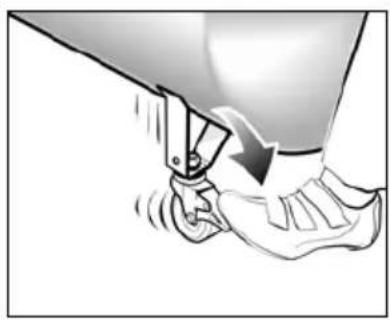
natural_image
Illustration of a foot pressing down on a curved object, showing motion and angle (no text or symbols)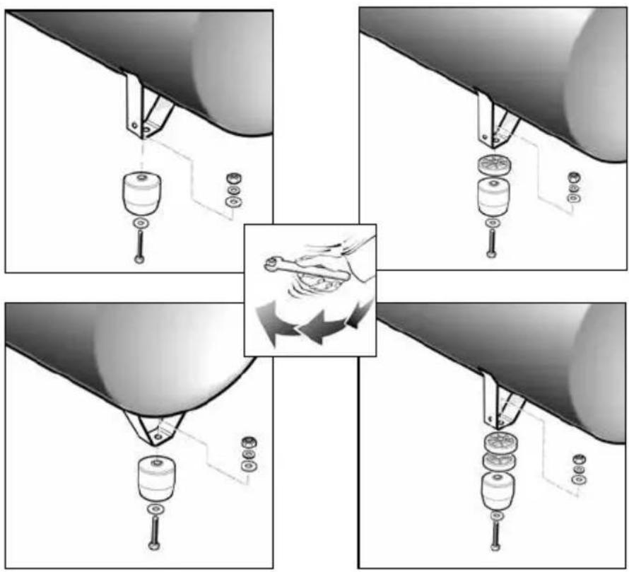
natural_image
Close-up of a droplet falling into a container (no text or symbols visible)A2
natural_image
Technical illustration of a mechanical assembly with a wheel and pin, showing exploded view (no text or symbols)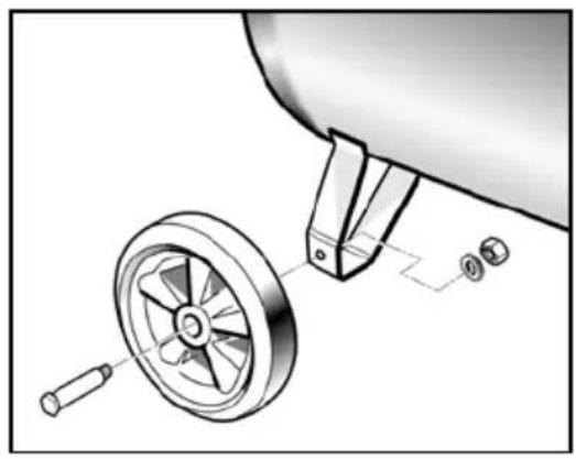
natural_image
Technical illustration of a mechanical assembly with a wheel and adjustment parts (no text or symbols)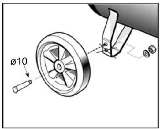
natural_image
Illustration of a hand using a tool to lift a car wheel, with motion arrows indicating speed (no text or symbols)A3
Section B
natural_image
Close-up of a hand pressing a component with a black arrow pointing to it, next to a cable (no visible text or symbols)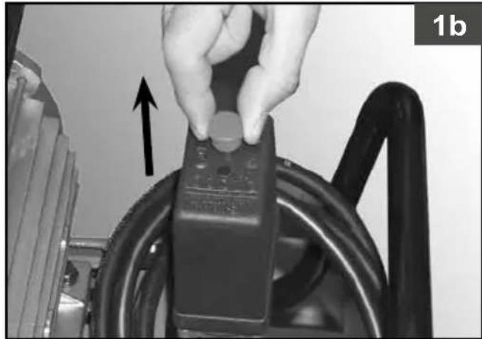
natural_image
Close-up of a hand holding a remote control device next to a car tire, with an upward arrow indicating motion (no text or symbols visible)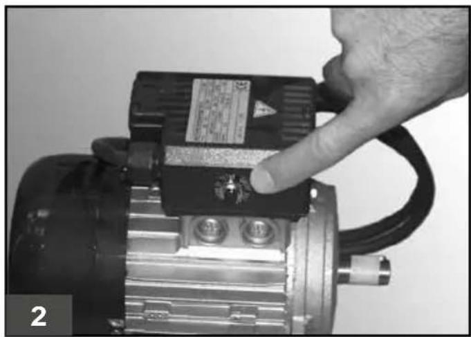
natural_image
Close-up of a hand adjusting an electric motor with a handle, showing no visible text or symbols.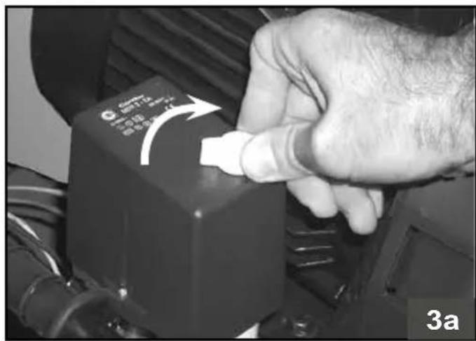
natural_image
Close-up of a hand pressing a button on a black electronic device, no visible text or symbols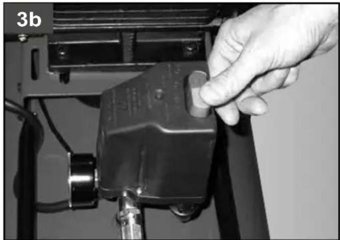
natural_image
Close-up of a hand adjusting a mechanical device component (no visible text or symbols)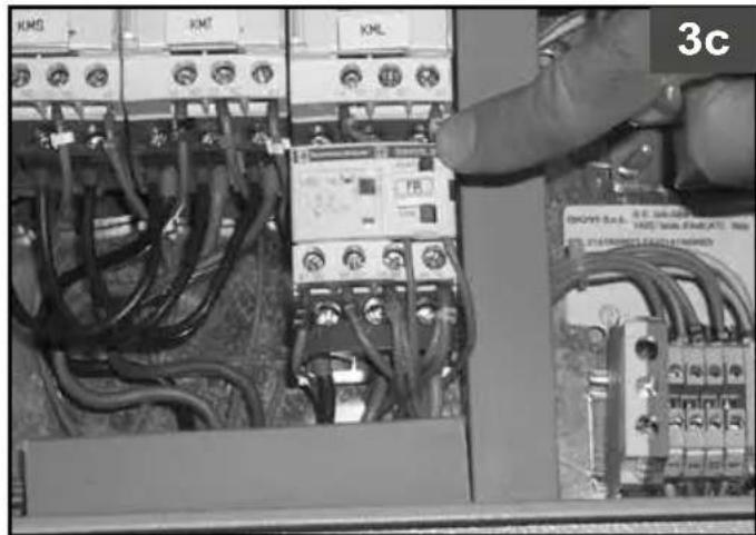
natural_image
Close-up of hands installing or adjusting electrical wiring on an electronic control panel (no visible text or symbols)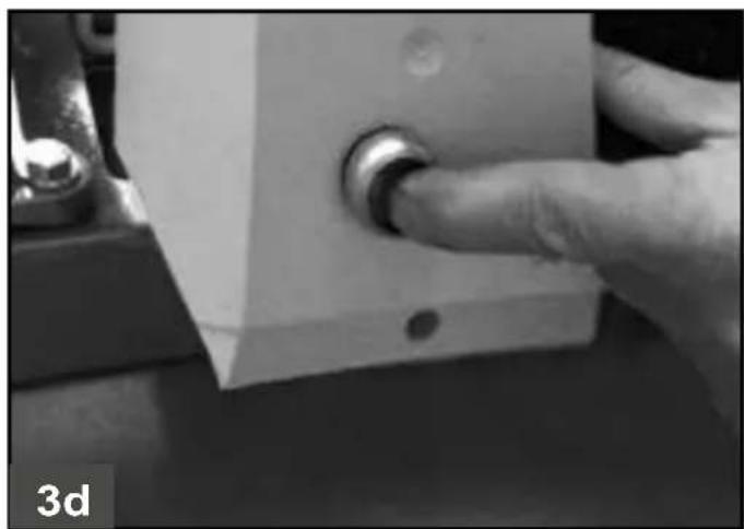
natural_image
Close-up of a finger pressing a button on a mechanical component (no visible text or symbols)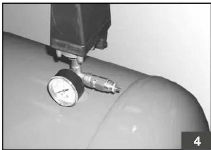
natural_image
Close-up of a pressure gauge mounted on a cylindrical tank (no visible text or symbols)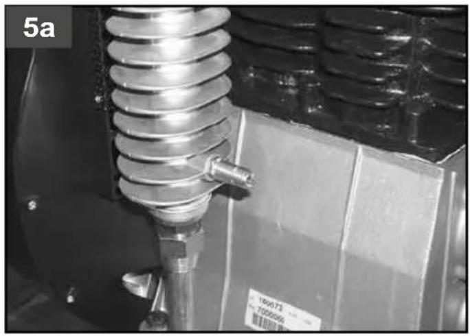
natural_image
Close-up of a metallic industrial spring assembly with a pipe fitting, next to a box (no visible text or symbols)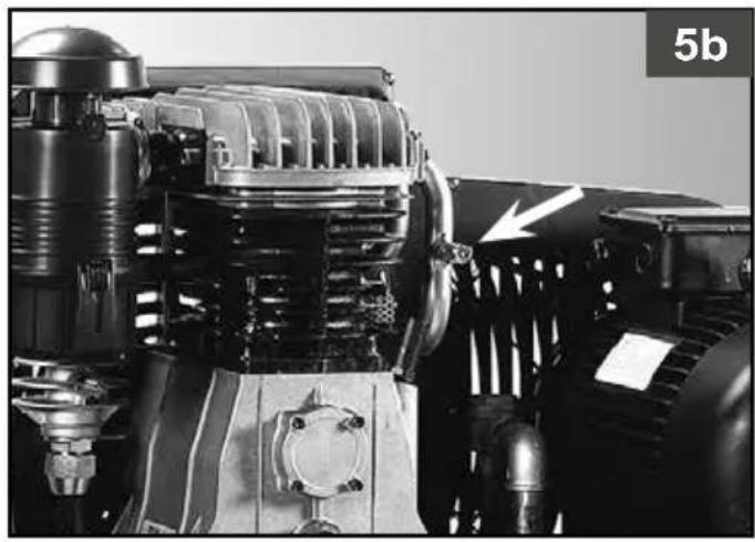
natural_image
Close-up of a mechanical engine component with visible internal gears and housing (no text or symbols)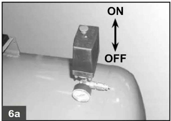

natural_image
Close-up of a mechanical component with a central bolt and arrow indicator (no text or symbols)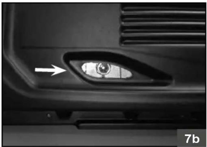
natural_image
Close-up of a car's side profile showing the eye and vent, with an arrow pointing to the lens (no text or symbols visible)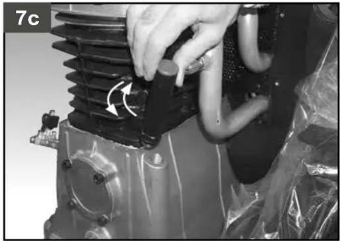
natural_image
Close-up of a mechanical component with a hand adjusting a spring and cooling pipes, wrapped in plastic (no visible text or symbols)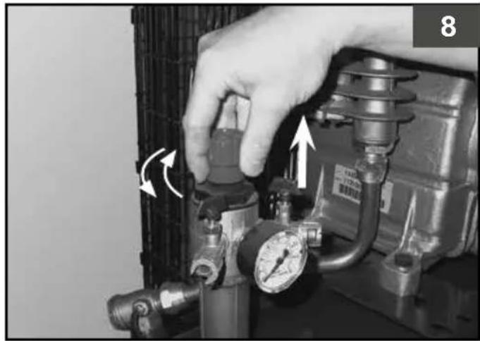
natural_image
Close-up of a hand adjusting a pressure regulator with directional arrows indicating motion (no text or symbols visible)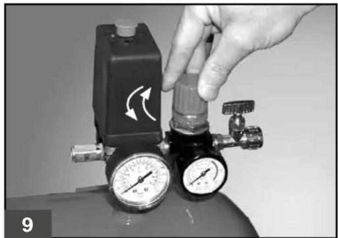
natural_image
Close-up of a hand adjusting a pressure regulator with two gauges and a valve, showing rotational flow arrows (no text or symbols visible)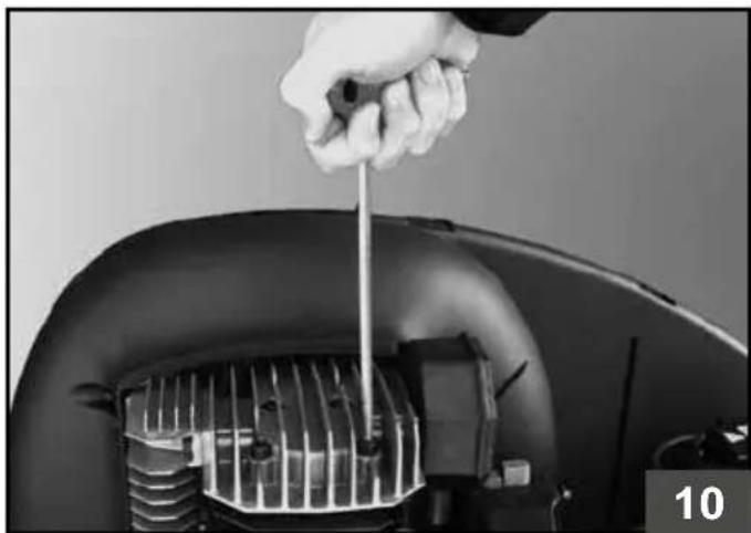
natural_image
Close-up of a hand using a screwdriver to adjust or install a car engine component (no visible text or symbols)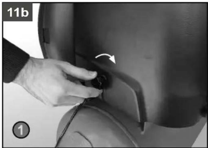
natural_image
Close-up of a hand adjusting a small black object on a dark surface, with no visible text or symbols.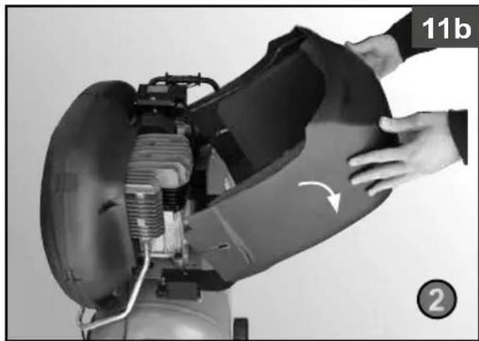
natural_image
Close-up of a mechanical device with hands operating it, showing internal components and a curved arrow indicating rotation (no text or symbols)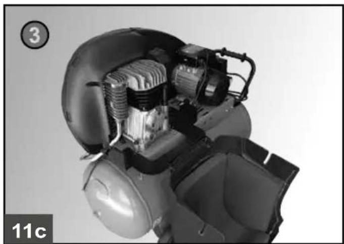
natural_image
Cutaway view of an internal combustion engine component (no text or symbols visible)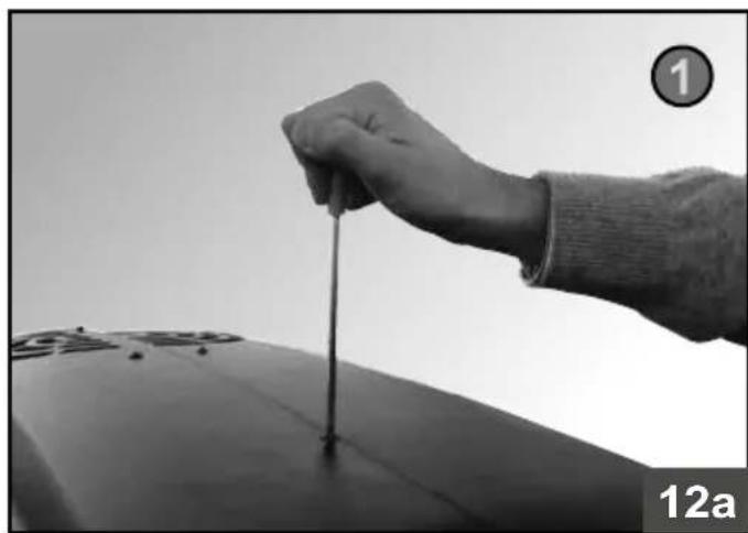
natural_image
Close-up of a hand holding a thin rod above a dark cylindrical object, with no visible text or symbols.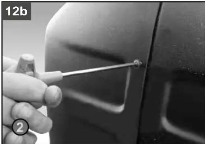
natural_image
Close-up of a hand holding a screwdriver near a car door, no visible text or symbols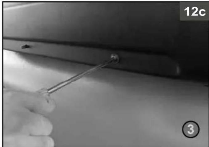
natural_image
Close-up of a hand holding a metal tool near a small circular object, with no visible text or symbols.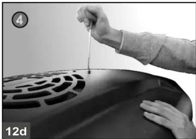
natural_image
Close-up of hands pouring liquid into a car grille (no visible text or symbols)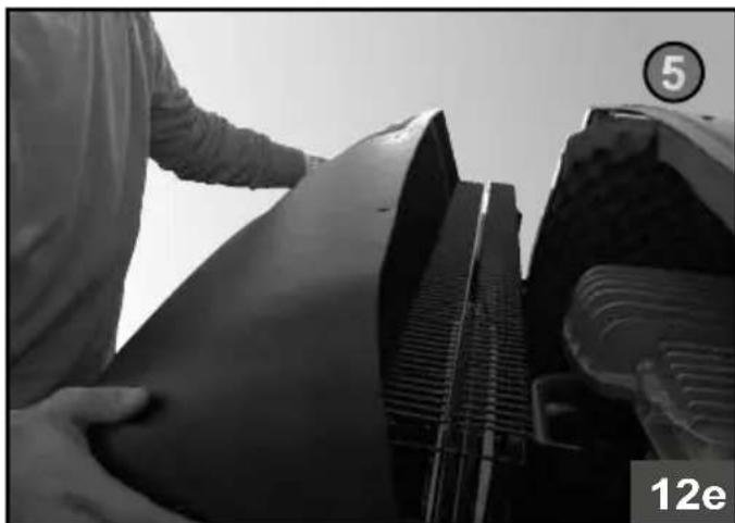
natural_image
Black-and-white photo of a person adjusting a large mechanical component, possibly a vehicle or industrial component, with no visible text or symbols.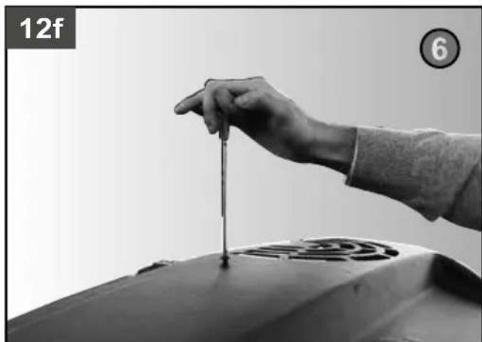
natural_image
Close-up of a hand pressing down on a mechanical component, no visible text or symbols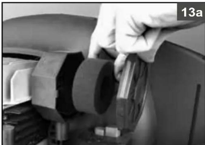
natural_image
Close-up of a hand adjusting a mechanical component with a bolt and nut (no visible text or symbols)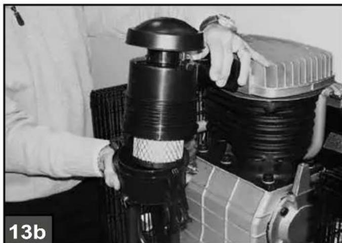
natural_image
Close-up of hands adjusting a black mechanical component with a textured base (no visible text or symbols)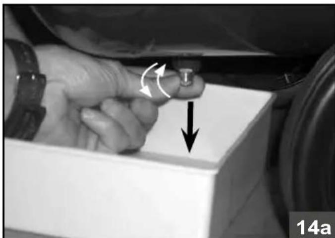
natural_image
Close-up of a hand adjusting a small component with directional arrows indicating motion (no text or symbols)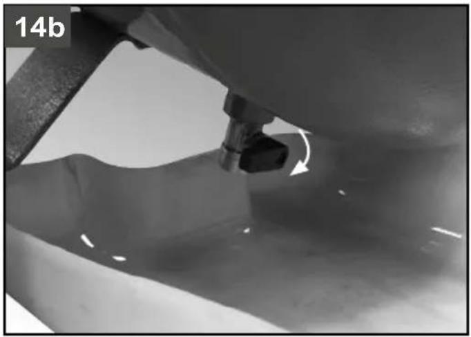
natural_image
Close-up of a mechanical component with a curved arrow indicating motion, no visible text or symbols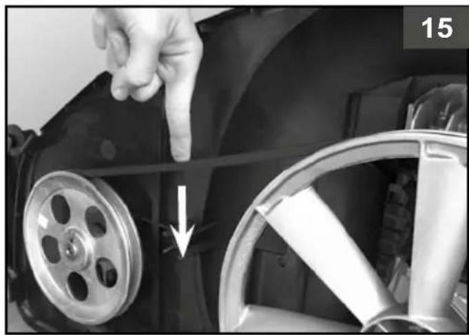
natural_image
Close-up of a hand pointing to a car wheel rim, with a white arrow indicating the wheel rim's direction (no text or symbols visible)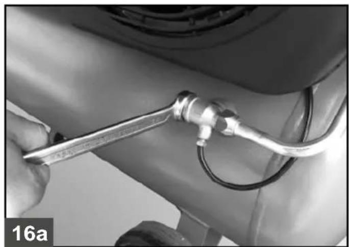
natural_image
Close-up of a hand using a wrench to adjust a car's engine component (no visible text or symbols)
natural_image
Close-up of hands assembling a metallic mechanical component (no visible text or symbols)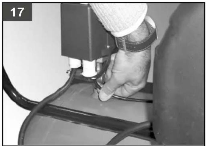
natural_image
Close-up of a hand using a device to press or install a component, no visible text or symbols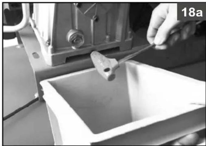
natural_image
Close-up of a hand using a tool to clean or wash material inside a plastic container (no visible text or symbols)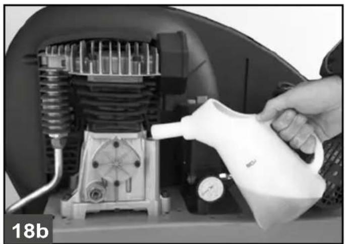
natural_image
Person pouring liquid into a mechanical engine component (no visible text or symbols)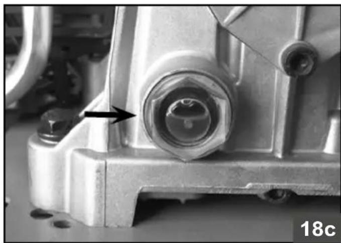
natural_image
Close-up of a mechanical component with a bolt and nut assembly, showing no visible text or symbols.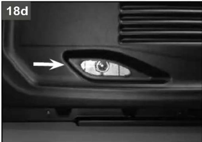
natural_image
Close-up of a car's side profile showing the eye and vent, with an arrow pointing to the lens (no text or symbols visible)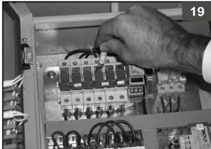
natural_image
Close-up of hands installing or repairing an electrical control panel with visible wiring and components (no text or symbols) | |
| I Leggere attentamente il manuale d'istruzioni prima dell'uso | |
| GB Before use, read the handbook carefully | |
| F Lire attentivement le Manuel Opérateur avant toute utilisation | |
| D Vor Inbetriebnahme Gebrauchsanleitung aufmerksam lesen | |
| E | Leer atentamente el manual de instrucciones antes de usar el equipo |
| P Ler com atenção o manual de instruções antes do uso | |
| NL Lees vóór gebruik aandachtig de handleiding door | |
| DK Laes omhyggeligt instruktionsmanualen før brug | |
| S Läs bruksanvisningen noggrant före användning | |
| FIN Lue käyttöopas huolellisesti ennen käyttöä | |
| GR Διαβάστε προσεκτικά το εγχειρίδιο οδηγιώνν πριν από τη χρήση | |
| PL Przed użyciem należy dokładnie zapoznać się z instrukcjami obsługi | |
| HR Prije upotrebe, pažljivo pročitajte upute za upotrebu | |
| SLO Pred zagonom skrbno preberite navodila za uporabo | |
| H Használat előtt figyelmesen olvassa el a kézikönyvet | |
| CZ Před zahájením práce si pozorně přečtěte příručku pro použiti. | |
| SK Pred používaním výrobku si pozorne prečítajte návod na jeho použitie. | |
| RUS Перед тем, как приступить к работе, внимательно прочитайте инструкцию по эксплуатации | |
| NO Les nøye bruksanvisningen før bruk | |
| TR Kullanımdan önce kullanım kılavuzunu dikkatlice okuyunuz. | |
| RO Citiți cu atenție manualul de instrucțiuni înainte de utilizare! | |
| BG Внимателно прочетете ръководството по експлоатация преди употреба | |
| SRB Pre upotrebe pažljivo pročitajte uputstva za upotrebu | |
| LT Prieš imdamiesi darbo atidžiai perskaitykite naudojimo vadovėlį | |
| EST | Enne kasutamist lugege kasutamisjuhend tähelepanelikult läbi. |
| LV | Uzmanīgi izlasiet izmantošanas instrukciju pirms produkta lietošanas |
 | |
| I | Pericolo di scottature |
| GB | Warning, hot surfaces |
| F | Risque de brûlures |
| D | Verbrennungsgefahr |
| E | Peligro de quemaduras |
| P | Perigo de queimaduras |
| NL | Gevaar voor brandwonden |
| DK | Risiko for skoldning |
| S | Risk för brännskador |
| FIN | Palovammavaara |
| GR | Kívðuvoc εγκαυμάτων |
| PL | Uwaga, grozi poparzeniem |
| HR | Pozor, vruće površine |
| SLO | Nevarnost opeklin |
| H | Figyelem, égető felületek |
| CZ | Nebezpečí spálení! |
| SK | Nebezpečenstvo popálenia ! |
| RUS | Опасность ожога |
| NO | Fare for à brenne seg |
| TR | Yanma tehlikesi |
| RO | Pericol de arsuri |
| BG | Опасност от изгаряния |
| SRB | Opasnost od opekotina |
| LT | Nudegimo pavojus |
| EST | Süttivuse oht |
| LV | Piesargieties no apdedzināšanās |
| I Protezione obbligatoria della vista | |
| GB Obligatory eye protection | |
| F Protection des yeux obligatoire | |
| D Sichtschutz obligatorisch | |
| E | Protección obligatoria de la vista |
| P Proteção obrigatória dos olhos. | |
| NL Beschermingsplicht voor het gezicht | |
| DK Obligatoriske beskyttelsesbriller | |
| S Obligatoriska skydglasögon | |
| FIN Pakollinen silmien suojaus | |
| GR Υποχρεωτική προστασία όρασης | |
| PL Obowiązkowe zabezpieczenie wzroku | |
| HR Obavezna zaštita za očiju | |
| SLO Obvezna zaščita oči | |
| H Kötelező szemvédelem | |
| CZ Povinná ochrana izraku | |
| SK Povinná ochrana izraku | |
| RUS Обязательная защита зрения | |
| NO Obligatorisk beskyttelse av synet | |
| TR Mecburi olarak gőzlerin korunması | |
| RO Protejarea obligatorie a vederii | |
| BG Задължителна защита на очите | |
| SRB Obavezna zaštita očiju | |
| LT Privalomi apsauginiai akiniai | |
| EST | Kohustuslik silmakaitse |
| LV | Obligāta redzes aizsārdzība |
 | |
| I Pericolo avviamento | automatico |
| GB Danger - automatic control (closed loop) | |
| F Risque de démarrage automatique | |
| D Gefahr durch automatischen Anlauf | |
| E Peligro de arranque | automático |
| P Perigo arranque | automático |
| NL Gevaar voor automatisch starten | |
| DK Fare automatisk start | |
| S Risk för automatisk | start |
| FIN Automaattisen káynnistymisen vaara | |
| GR Kívðuvoς autóμορης εκκίνησης | |
| PL Uwaga, niebezpieczeństwo automatycznego uruchomienia się | |
| HR Opasnost zbog automatskog pokretanja | |
| SLO Nevarnost zaradi samodejnega zagona | |
| H Automatikus beindulás veszélye | |
| CZ Nebezpečí - automatické spouštění! | |
| SK Nebezpečenstvo - automatické spustenie ! | |
| RUS Опасность автоматического включения | |
| NO Fare for automatisk oppstart | |
| TR Dikkat otomatik çalışma tehlikesi | |
| RO Pericol pornire automată | |
| BG Опасност от автоматично пускане в ход | |
| SRB Opasnost zbog automatskog pokretanja | |
| LT Automatinio jsijungimo pavojus | |
| EST | Ohtlik - automaatiline käivitus |
| LV | Uzmanību - automātiska iedarbināšanās |
| I | Attenzione corrente elettrica |
| GB | Dangerous voltage |
| F | Attention: présence de courant électrique |
| D | Achtung, elektrische Spannung |
| E | Atención, corriente eléctrica |
| P | Atenção corrente eléctrica |
| NL | Attentie, elektrische stroom |
| DK | Advarsel elektrisk strøm |
| S | Varning - elektricitet |
| FIN | Huom. vaarallinen jännite |
| GR | Проσοχή ηλεκτρικό ρεύμα |
| PL | Uwaga, niebezpieczeństwo porążenia prądem elektrycznym |
| HR | Pažnja, električni napon |
| SLO | Pozor, električna napetost |
| H | Figyelem, elektromos áram |
| CZ | Pozor - elektrické napětí! |
| SK | Pozor - elektrický prúd ! |
| RUS | Опасность удара электрическим током |
| NO | Forsiktig elektrisk strøm |
| TR | Dikkat elektrik akımı |
| RO | Atenție! Pericol electric |
| BG | Внимание: електричеки ток |
| SRB Pažnja, električni napon | |
| LT | Elektros įtampos rizika |
| EST | Ettevaatust - elektrivool |
| LV | Esiet uzmanīgi - elektrības plūsma |
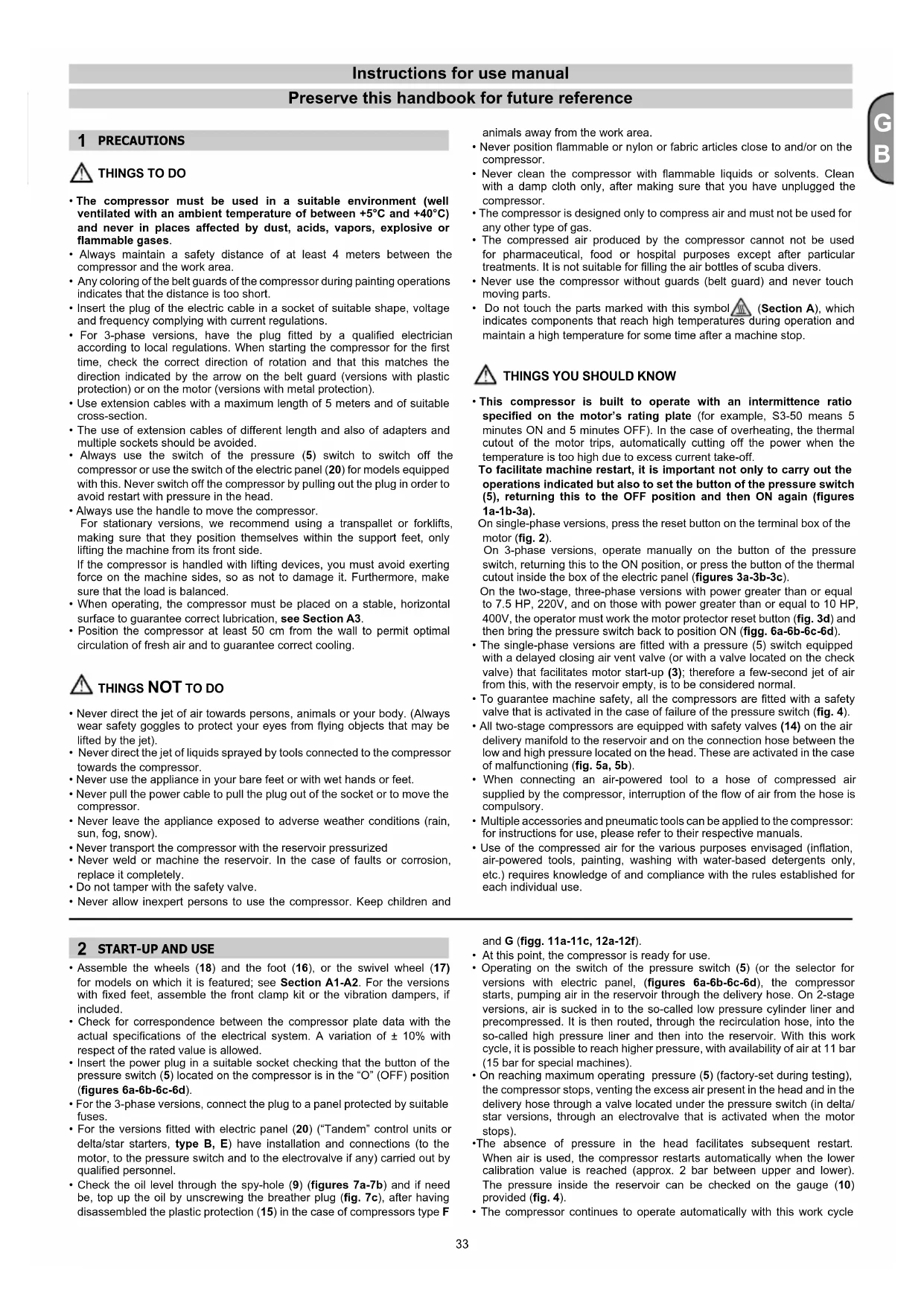
| I | Gruppo pompante |
| GB | Pumping unit |
| F | Groupe pompant |
| D | Pumpgruppe |
| E | Grupo de bombeo |
| P | Unidade de bombeamento |
| NL | Pompgroep |
| DK | Pumpeaggregat |
| S | Pumpenhet |
| FIN | Pumppuryhmä |
| GR | Аvtлніткó суукрόтніа |
| PL | Zespół Pompujący |
| HR | Pumpna grupa |
| SLO | Črpalna enota |
| H | Szivattyú egység |
| CZ | Systém vstřikovacího čerpadla |
| SK | Vstrekovacia sústava |
| RUS | Компрессорная головка |
| NO | Pumpe Gruppe |
| TR | Pompalama grubu |
| RO | Grup de pompare |
| BG | Изпомпваща група |
| SRB | Pumpna grupa |
| LT | Pompavamo jrenginys |
| EST | Kompressori pump |
| LV | Sūkņu grupa |
| I Potenza motore | |
| GB Power | |
| F Puissance moteur | |
| D Motorleistung | |
| E | Potencia motor |
| P Potência do motor | |
| NL Motorvermogen | |
| DK Motorstyrke | |
| S Motorstyrka | |
| FIN Moottorin teho | |
| GR Iɔχύς κινητήρα | |
| PL Moc silnika | |
| HR Snaga motora | |
| SLO Moč motorja | |
| H Motor teljesítménye | |
| CZ Výkon motoru | |
| SK Výkon motora | |
| RUS Мощность мотора | |
| NO Effekt motor | |
| TR Motor gücü | |
| RO Puterea motorului | |
| BG Мощност на двигателя | |
| SRB Snaga motora | |
| LT Variklio galingumas | |
| EST | Mootori võimsus |
| LV | Motora jauda |
 | |
| I Capacità serbatoio | |
| GB Tank capacity | |
| F Contenance réservoir | |
| D Behältergröße | |
| E | Capacidad depósito |
| P Capacidade do reservatório | |
| NL Tankcapaciteit | |
| DK Brændstoftank, kapacitet | |
| S Bränsletank, kapacitet | |
| FIN Sälliön tilavuus | |
| GR Ikavótna pečepšouáp | |
| PL Pojemność zbiornika | |
| HR Kapacitet tlačne posude | |
| SLO Velikost tlačne posode | |
| H A tartály úrtartalma | |
| CZ Objem nádrže | |
| SK Objem nádrže | |
| RUS Obъем ресивера | |
| NO Kapasitet magasin | |
| TR Depo kapasitesi | |
| RO Capacitatea rezervorului | |
| BG Kapaçitet na perezervoara | |
| SRB Kapacitet rezervoara | |
| LT Bako talpa | |
| EST | Paagi mahutavus |
| LV | Rezervuāra ietilpība |
| I Aria aspirata | |
| GB Air intake | |
| F Air aspiré | |
| D Eingesaugte Luft | |
| E | Aire aspirado |
| P Ar aspirado | |
| NL Geaspireerde lucht | |
| DK Luftforbrug | |
| S Luftförbruk | |
| FIN Imetty ilma | |
| GR Апоррофоύμενος αέρας | |
| PL Powietrze zasysahe | |
| HR Usis zraka | |
| SLO Količina sesanega zraka | |
| H Elszivolt levegő | |
| CZ Nasávaný vzduch | |
| SK Nasávaný vzduch | |
| RUS Производительность | |
| NO Aspirert luft | |
| TR İçine çekilen hava | |
| RO Debit aspirat | |
| BG Всмукан въздух | |
| SRB Usisivanje vazduha | |
| LT Išsiurbtas oras | |
| EST | Åra imetav ōhk |
| LV | lesūktais gaiss |
 | |
| I | Corrente assorbita |
| GB | Absorbed current |
| F | Courant Absorbé |
| D | Verbrauchter Strom |
| E | Corriente absorbida |
| P | Corrente absorvida |
| NL | Opgenomen stroom |
| DK | Strømforbrug |
| S | Strömförbrukning |
| FIN | Ottovirta |
| GR | Katavaškočevo peúμα |
| PL | Prąd Pobrany |
| HR | Absorbirana energija |
| SLO | Absorbirani električni tok |
| H | Elnyelt áram |
| CZ | Spotřeba el. energie |
| SK | Prúdová spotreba |
| RUS | Потребляемый ток |
| NO | Strøm Absorbert |
| TR | Çekilen enerji |
| RO | Curent absorbit |
| BG | Консумиран ток |
| SRB | Absorbovana energija |
| LT | Sugerta el. srovė |
| EST | Kasutatav elektrivool |
| LV | Elektriskās strāvas Patērinš |
| I Pressione max. | |
| GB Max. pressure | |
| F Pression max. | |
| D maximaler Druck. | |
| E | Presión máx. |
| P Pressão máxima | |
| NL Max. druk | |
| DK Max. tryk | |
| S Max. tryck | |
| FIN Paine enint. | |
| GR Avútatn tíeşŋ | |
| PL Ciśnienie max. | |
| HR Najveći tlak | |
| SLO Maksimalni tlak | |
| H Maximális nyomás | |
| CZ Maximální tlak | |
| SK Max. tlak | |
| RUS Максимальное давление | |
| NO Maks. trykk | |
| TR Maksimum basinç | |
| RO Presiunea max. | |
| BG Maks. налягане | |
| SRB Najveći pritisak | |
| LT Maks. slégis | |
| EST | Maksimum surve |
| LV | Maks. Spiediens |
 | |
| I Giri / min. | |
| GB Revolutions / min. (rpm) | |
| F Tours / mn | |
| D U/min | |
| E | Revoluciones / mln. |
| P Rotações / minutos | |
| NL Toerentallen per minuut | |
| DK Omdrejninger / min | |
| S Varv / min | |
| FIN Kierrosta / min | |
| GR Στροφές / λεπτά | |
| PL Obroty / min | |
| HR Okretaji / min | |
| SLO Vrt./Min | |
| H Fordulatszám / perc | |
| CZ Otáčky / min | |
| SK Otáčky / min | |
| RUS Обороты/мин. | |
| NO Omdreininger / min | |
| TR Devir / dakika | |
| RO Rotații / min. | |
| BG Обороти / мин | |
| SRB Broj obrtaja / min | |
| LT Apsukos / min | |
| EST | Pööret / min |
| LV | Apgriezieni/min |
| I Tensione e frequenza | |
| GB Voltage and frequency | |
| F Tension et fréquence | |
| D Spannung und Frequenz | |
| E | Tensión y frecuencia |
| P Tensão e frequência | |
| NL Spanning en frequentie | |
| DK Spænding og frekvens | |
| S Spänning och frekvens | |
| FIN Jännite ja taajuus | |
| GR Táon kai suxvótna | |
| PL Napięcie i częstotliwość | |
| HR Napon i frekvencia | |
| SLO Napetost in frekvencia | |
| H Feszültség és frekvencia | |
| CZ Napāti a frekvence | |
| SK Napätie a frekvencia | |
| RUS Напряжение и частота | |
| NO Spenning og frekvens | |
| TR Gerilim ve frekanş | |
| RO Tensiune şi frecvență | |
| BG Напрежение и честота | |
| SRB Napon i frekvencija | |
| LT | Itampa ir dažnis |
| EST | Pinge ja sagedus |
| LV | Spriegums un frekvence |
 | |
| I Quantità di olio | |
| GB Oil amount | |
| F Quantité huile | |
| D Ölmenge | |
| E | Cantidad de aceite |
| P Quantidade de óleo | |
| NL Hoeveelheid olie | |
| DK Oliemængde | |
| S Oljemängd | |
| FIN Öljyn määrä | |
| GR Ποσότητα λαδιού | |
| PL Ilość oleju | |
| HR Kolicina ulja | |
| SLO Količina olja | |
| H Olajmennyiség | |
| CZ Množství oleje | |
| SK Množstvo oleja | |
| RUS количество маєла | |
| NO Kvantitet olje | |
| TR Yağ miktarı | |
| RO Cantitate ulei | |
| BG Количество маєло | |
| SRB Kolicina ulja | |
| LT | Alyvos kiekis |
| EST | Õli hulk |
| LV | Elljas daudzums |
| I Sezione cavo di alimentazione | |
| GB Power cable cross section | |
| F Section câble d'alimentation | |
| D Speisekabelschnitt | |
| E | Sección del cable de alimentación |
| P Bitola do cabo de alimentação | |
| NL Doorsnede voedingskabel | |
| DK Forsyningskabel šnit | |
| S Sektion för kraftkabel | |
| FIN Syöttökaapelin pikkipinta-ala | |
| GR Διατομή Καλωδίου Τροφοδοσίας | |
| PL Przekrój Kabla zasilającego | |
| HR Sekcija napojnog kable | |
| SLO Sklop Napajalni kabel | |
| H Tápvezeték cső metszet | |
| CZ Průměr napájecího kabelu | |
| SK Prierez napájacie ho kábla | |
| RUS сечение токоподводящего кабеля | |
| NO Avdeling matekabel | |
| TR Besleme kablosu kesiti | |
| RO Sectiune cablu de alimentare | |
| BG Секция захранващ кабел | |
| SRB Presek napojnog kable | |
| LT Maitinimo kabelio skyrius | |
| EST | Toitekaabli ristlõige |
| LV | Barošanas kabela Sekcija |
natural_image
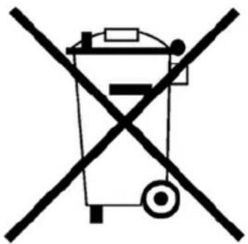
Symbol of a trash bin crossed out by a diagonal line, representing no waste or elimination (no text or labels present)
| I | L'apparecchio non può essere smaltito nei normali rifiuti domestici.Questo apparecchio dispone di contrassegno ai sensi della direttiva europea 2012/19/UE in materia di apparecchi elettrici ed elettronici (waste electrical and electronic equipment - WEEE).Questa direttiva definisce le norme per la raccolta e il riciclaggio degli apparecchi dismessi valide su tutto il territorio dell'Unione Europea. Per la restituzione di un dispositivo dismesso, si prega di servirsi dei sistemi di restituzione e di raccolta messi a disposizione nei singoli paesi di utilizzo. |
| GB | The device may not be disposed of with household rubbish.This appliance is labelled in accordance with European Directive 2012/19/UE concerning used electrical and electronic appliances (waste electrical and electronic equipment - WEEE).The guideline determines the framework for the return and recycling of used appliances as applicable throughout the EU. To return your used device, please use the return and collection systems available to you. |
| F | Il est interdit d'éliminer l'appareil avec les déchets urbains (déchets ménagers).Cet appareil est marqué selon la directive européenne 2012/19/UE relative aux appareils électriques et électroniques usagés (waste electrical and electronic equipment - WEEE).La directive définit le cadre pour une reprise et une récupération des appareils usagés applicables dans les pays de la CE. Pour renvoyer votre ancien appareil, utilisez les systèmes de renvoi et de collecte qui vous sont proposés. |
| D | Das Gerät darf nicht mit dem Siedlungsabfall (Hausmüll) entsorgt werden.Dieses Gerät ist entsprechend der europäischen Richtlinie 2012/19/UE über Elektro- und Elektronik-Altgeräte (waste electrical and electronic equipment - WEEE) gekennzeichnet.Die Richtlinie gibt den Rahmen für eine EU-weit gültige Rücknahme und Verwertung der Altgeräte vor. Für die Rückgabe Ihres Altgeräts nutzen Sie bitte die Ihnen zur Verfügung stehenden Rückgabe- und Sammelsysteme. |
| E | El equipo no debe eliminarse junto con la basura urbana (basura doméstica).Este aparato está marcado con la Directiva europea 2012/19/UE relativa al uso de aparatos eléctricos y electrónicos (waste electrical and electronic equipment - WEEE).La directiva proporciona el marco general válido en todo el ámbito de la Unión Europea para la retirada y la reutilización de los residuos de los aparatos eléctricos y electrónicos. Para la devolución de su antiguo dispositivo utilice los sistemas de recogida y devolución disponibles y específicos. |
| P | O aparelho não pode ser eliminado junto com os residuos domésticos normais.Esse aparelho dispõe de marca nos termos da diretiva europeia 2012/19/UE em matéria de aparelhos elétricos e eletrónicos (Resíduos de Equipamentos Elétricos e Eletrónicos - REEE).Essa diretiva define as normas para a recolha e reciclagem dos aparelhos desativados válidos em todo o território da União Europea. Para a restituição de um dispositivo desativado, solicitamos utilizar os sistemas de restitulição e recolha colocados a disposição no país de utilização. |
| NL | Dit apparaat mag niet als ongesorteerde stedelijke afval verwijderd worden.Dit apparaat is gemarkeerd zoals voorgeschreven door de Europese richtlijn 2012/19/EU inzake elektrische en elektronische apparatuur (waste electrical and electronic equipment - WEEE).Deze richtlijn bepaalt de normen voor de inzameling en terugwinning van afgedankte apparatuur, geldig op het grondgebied van de Europese Unie. Voor het retourmeren van een afgedankt apparaat, gelieve de retour- en inzamelingssystemen te gebruiken, ter beschikking gesteld in het land van gebruik. |
| DK | Apparatet må ikke afskaffes med det amindelige husholdningsaffald.Dette apparat er mærket i overensstemmelse med det europæiske direktiv 2012/19/EU om elektrisk og elektronisk udstyr (WEEE).Dette direktiv definerer normerne for indsamling og genanvendelse af brugte apparater og er gældende i hele den Europæiske Union. For aflevering af brugte apparater, skal de systemer der stiles til rådighed i de enkelte lande, anvendes til bortskaffelse. |
| S | Apparaten får inte bortskaffas tillsammans med normalt hushållsavfall.Denna apparat är försedd med märkning enligt det europeiska direktivet 2012/19/EU beträffande elektriska och elektroniska apparater (waste electrical and electronic equipment - WEEE).Detta direktiv fastställer de regler, som gäller för insamling och återvinning av kasserade apparater i hela den Europeiska Unionen.För återlämnande av en kasserad anordning, använd de återvinnings- och insamlingssystem, som ställts till förfogande i de enskilda användarländerna. |
| FIN | Laitetta ei saa hävittää kotitalousjätteen mukana.Tässä laitteessa on sähkö- ja elektroniikkalaiteromua koskevan EU-direktiivin 2012/19/EY mukainen merkintä (Waste Electrical and Electronic Equipment - WEEE).Kyseinen direktiivi määrittää käytöstä poistettujen laitteiden keräykseen ja kierrätykseen liittyvät määräykset kaikissa EU-maissa. Käytöstä poistetun laitteen palauttamista varten, käänny käyttömaissa käytössä olevien palautus- ja keräysjärjestelmien puoleen. |
| GR | H συσκευή δεν πρέπει να απορρίπτεται μαζί με τα κοινά αστικά απορρίμματα.H παρούσα συσκευή διοθέτει ειδίκη σήμανον βάσει της ευρωταϊκής οδηγίας 2012/19/E.E. περί ηλεκτρικών και ηλεκτρονικών συσκευών (waste electrical and electronic equipment - WEEE).H προαναφερθείσα οδηγία προσδιορίζει του κανόνες συλλογής και ανακύκλωσης παλαιών συσκευών σε όλη την επικράτεια της Ευρωταϊκής Ένωσης.Για την απόρριμη μιας τέτοιας συσκευής, παρακαλώ απευθυνθείτε στα ειδικά κέντρα παραλαβής και συλλογής των μεμονωμένων χώρων όπου αυτή χρησιμοποιήθηκε. |
| PL | Urządzenia nie wolno wyrzucać do zwyczajnych odpadów domowych.Niniejsze urządzenie jest oznaczone zgodnie z Dyrektywą Europejską 2012/19/WE dotyczącą sprzętu elektrycznego i elektronicznego (waste electrical and electronic equipment - WEEE).Dyrektywa ta określa zasady usuwania i recyklingu wycofanych urządzeń obowiązujące na calym terytorium Unii Europejskiej. W celu oddania wycofanego urządzenia, należy skorzystać z systemów zwrotu i zbiórki dostępnych w krajach użytkowania. |
| HR | Uređaj se ne smilje odlagati u normalnom kućnom otpаду.Uređaj ima oznaku sukladno europskoj direktivo 2012/19/EU o električnoj i elektroničkoj opremi (waste electrical and electronic equipment - WEEE).Ova direktiva propisuje pravila prikupljanja i reckiliranja rastavljenih uređaja diljem Europske unije. Za vraćanje odbačenog uređaja upotrijebite sustave povrata i prikupljanja koji su dostupni u zemljama u kojima se uređaji koriste. |
| SLO | Naprave ne smete odvreći med običajne gospodinjske odpadke.Ta naprava je nosi oznako v skladu z evropsko Direktivo 2012/19/EU o odpadni električni in elektronski opremi (OEEO).Ta direktiva opredeljiuje pravila o zbiranju in recikiliranu odrabljenih naprav, ki veljajo na celotnem območju Evropske unije. Odrabljene naprave vrnite prek sistemov vraćanja in zbiranja, ki so na voljo v posameznih državah uporabe naprave. |
| H | A berendezés nem hulladékkezelhető rendes, háztartási hulladékként.Ez a berendezés el van látva a 2012/19/UE európai irányelv értelmében, az elektromos és elektronikus berendezésekre vonatkozólag (waste electrical and electronic equipment - WEEE) a megfelelő jelézssel.Ez az irányelv meghatározza a hulladékolt berendezések begyűjtési és újrafelhasználási szabályokat, amelyek érvényesek az Európai Unió teljes területén belül. A hullakolt berendezés visszaszolgáltatásához kéřük, a visszaszolgáltatási és begyűjtési rendszereket használják, amelyek rendelkezésre állnak az egyes országokban. |
| CZ | Zařízení nemůže být zlikvidováno spolu s běžným domovním odpadem.Toto zařízení disponuje označením ve smyslu evropské směrnice 2012/19/EU v oblasti elektrických a elektronických zařízení (waste electrical and electronic equipment - WEEE).Tato směrnice definuje předpisy pro sběr a recyklaci vyřazených zařízení platné na celém území Evropské unije. Pro vrácení rozebraného zařízení, vás žádámе, abyste použili systémy nárvatu a sběru, které jsou k dispozici v jednotlivých zemích použití. |
| SK | Zariadenie nie je možné likvidovať spoločne s bežným domácim odpadom.Toto zariadenie je označené v súlade s európskou smernicou 2012/19/EU v oblasti odpadov z elektrických a elektronických zariadení - OEEZ (waste electrical and electronic equipment - WEEE).Tato smernica definuje normy pre zber a recykláciu zariadení, ktoré platia na celom území Európskej únie. Pre vrátenie vyradeného zariadenia využite prosím systémy vrátenia a zberu, ktoré sú k dispozicii v jednotlivých krajinách používania zariadenia. |
| RUS | Данный прибор нельзя выбрасывать вместе с обычными бытовыми отходами.На данном приборе имеется специальный знак в соответствии с европейской директивой 2012/19/EC об электрических и электронных приборах (waste electrical and electronic equipment - WEEE).Эта директива определяет действующие на всей территории Европейского Союза нормы по сбору и переработке вышедших из употребления приборов. Для сдачи вышедшего из употребления прибора пользуйтесь системами сбора, организованными в разных странах эксплуатации прибора. |
| NO | Apparatet må ikke kastes i vanlig husholdningsavfall.Dette apparatet er merket i henhold til det europeiske direktivet 2012/19/EU om elektrisk og elektronisk utstyr (WEEE).Dette direktivet fastsetter regler for innsamling og gjenbruk av demonterte apparater i hele EU. For å returnere et kassert apparat, må du benytte de retur- og innsamlingssystemene, som er tilgjengelige i de enkelte brukerlandene. |
| TR | Cihaz normal evsel atiklarla birlikte bertaraf edilemez.Bu cihaz, elektrik ve elektronik cihazlar konusunda 2012/19/AB Avrupa Birliği direktifine uygun olarak etiketlenmiştir (waste electrical and electronic equipment - WEEE).Bu direktif atilan cihazların toplanması ve geri döñüşümü için standartları tüm Avrupa Birliği bölgesinde geçerli olarak tanımlar. Atılan bir cihazın iadesi için cihazın kullanıldığı ülkede bulunan iade ve toplama sistemlerinden yararlanın. |
| RO | Aparatul nu trebuie să fie eliminat cu deseurile menajere.Acest aparat este marcat în conformitate cu Directiva Europeană 2012/19/UE privind aparatele electrice și electronice (waste electrical and electronic equipment - WEEE).Prezenta directivă stabileste normele pentru colectarea și reciclarea echipamentelor scoase din uz și sunt valabile pe întreg teritoriul Uniunii Europene.Pentru a preda un aparat scos din uz, vă rugăm să fološiti sistemele de recuperare și colectare puse la dispoziție în fiecare țară de utilizare |
| BG | Уредът не може да се изхвърля заедно с нормалните битови отпадцы.Този уред разполага с маркировка съгласно Европейската директива 2012/19/UE в сферата на електрическите и електронните уреди (отпадьци от електрическо и електронно оборудване - WEEE).Настоящата директива определя правилата за събиране и рециклиране на употребявани уреди, валидни на територията на Европейския съюз. За връщането на един употребяван уред, моля, използвайте системите за връщане и събиране, предоставени в отделните държави, в които той се употребява. |
| SRB | Uređaj se ne može odložiti u normalni otpад iz domaćinstva.Ovaj uređaj označen je u skladu sa evropskom direktivom 2012/19/EU o električnoj i elektronične opremi (otpad elektronske i električne opreme - WEEE).Ova direktiva definiše pravila za prikupljanje i recikliranje odbačenih uređaja važeća širom Evropske unije. Za vraćanje odbačenog uređaja, koristite sisteme za vraćanje i sakupljanje koji su dostupni u pojedinačnim zemljama u kojima se koristi. |
| LT | Prietaiso negalima šalinti kartu su jprastomis buitinémis atliekomis.Šis prietaisas yra paženklintas pagal Europos direktyvą 2012/19/ES dél elektros ir elektroninés įrangos atliekų (angl. „waste electrical and electronic equipment - WEEE“).Ši direktyva nustato nebenaudojamos įrangos surinkimo ir perdirbimo taisykles, taikomas visoje Europos Sąjungos teritorijoje. Norédami gražinti nebenaudojamą prietaisa, pasinaudokite atskirose naudojimo šalyse siūlomomis gražinimo ir surinkimo sistemomis. |
| EST | Seadet ei tohi kõrvaldada tavalise olmejätmena.See seade on märgistatud vastavalt Euroopa elektri- ja elektronikaseadmetest tekkinud jäätmete direktiivile 2012/19/EL (WEEE).See direktiiv kehtestab kasutuselt kõrvaldatud seadmete kogumise ja ringlussevõtu eeskirjad kogu Euroopa Liidu territooriumil. Kasutuselt kõrvaldatud seadmed tuleb tagastada vastavalt kasutusrigis kehtivatele tagastamis- ja kogumisvõimalustele. |
| LV | Ierici nedrikst izmest parastajos sadzīves atkritumos.Ši erīce ir marķēta saskaņā ar Europas direktivu 2012/19 / ES par elektriskām un elektroniskām iekārtām (EEIA elektriskās un elektroniskās iekārtas).Ši direktiva definė noteikumus par izbrāķētu ieriču savākšanu un pārstrādi, kas ir spēkā visā Europas Savienibā. Lai nodotu izbrāķētu ieriči, lādzu, izmantojiet nodošanas un savākšanas sistēmas, kas pieejamas atseviškās ierifics izmantošanas valstīs. |
flowchart
graph TD
    A["Warning Symbol"] --> B{Warning Event}
    B --> C["Warning Warning Icon"]
    C --> D{Warning Indicator}
    D --> E["Hand icon with 'C', 'L', 'W'"]
    E --> F["Hand icon with 'R', 'L', 'W'"]
    F --> G["Eye Icon with 'R', 'L', 'W'"]
    G --> H["Down Arrow"]
    style A fill:#f9f,stroke:#333
    style H fill:#ccf,stroke:#333
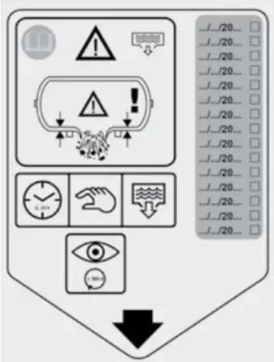
| I | Etichetta spurgo - spurgare il serbatoio ogni giorno - far controllare annualmente lo spessore della parete del serbatoio da un organismo notificato, annotando sull'etichetta la data dell'intervento. |
| GB | Drain label - drain out the tank daily - annually have the thickness of the tank walls checked by a competent body, recording the date of the service task on the label. |
| F | Étiquette de purge - purger le réservoir quotidiennement - faire contrôler annuellement l'épaisseur de la paroi du réservoir par un organisme compétent, en inscrivant la date d'intervention sur l'étiquette. |
| D | Entlüftungsetikett - den Druckluftbehälter täglich entlüften - jährlich die Wandstärke des Behälters von einer zuständigen Stelle prüfen lassen und das Datum der Überprüfung am Etikett vermerken. |
| E | Etiqueta de purga - purgar el depósito todos los días - anualmente encargar a un organismo competente un control del grosor de la pared, apuntando en la etiqueta la fecha de la actuación. |
| P | Etiqueta de purga - esvazie o reservatório a cada dia - deve ser verificada anualmente a espessura da parede do reservatório por parte de um organismo competente, observando na etiqueta a data da intervenção. |
| NL | Etiket ontluchting - ontlucht het reservoir dagelijks - laat jaarlijks de dikte van de wand van het reservoir controleren door een bevoegde instantie en noteer de datum van de werkzaamheid op het etiket. |
| DK | Udløbets etiket - tøm tanken hver dag - lad tankens vægtykkelse kontrollere en gang om året af et kompetent organ og anfør kontroldatoen på etiketten. |
| S | Tömningsetikett - töm tanken varje dag - låt årligen kontrollera tankväggarnas tjocklek av ett kompetent organ, notera datumet på etiketten för inspektionen. |
| FIN | Tyhjennyksen etiketti - tyhjennä säiliö päivittäin - tarkastuta säiliön seinän paksuus vuosittain pätevällä laitoksella; toimenpiteen suorituspäivä tulee merkitä etikettiin. |
| GR | Επικέτα αποστράγγισης - να εκτελείτε καθημερινή αποστράγγιση της δεξαμενής- να αναθέτετε ετησίως τον έλεγχο του πάχους των τοιχωμάτων της δεξαμενής σε αρμόδιο φορέα, και να καταγράφετε την ημερομηνία του σέρβις στην ετικέτα. |
| PL | Zawieszka spustu – opróżniaj zbiornik codziennie – co roku należy zlecić sprawdzenie grubości ścian zbiornika organowi o odpowiednich kompetencjach, z zapisem daty czynności serwisowej na zawieszce. |
| HR | Oznaka za odvod – spremnik praznite svakodnevno – svake godine provjeravajte debljinu stijenke spremnika pri nadležnom tijelu koje će na oznaci naznačiti datum posljednjeg servisa spremnika. |
| SLO | Oznaka za praznjenje – rezervoar izpraznite vsak dan – ustrezni strokovni organ mora vsako leto izvesti pregled oz. meritev debeline stene rezervoarja in na nalepko navesti datum servisnega pregleda. |
| H | Leeresztő címke - naponta eressze le a tartályt - évente ellenőriztesse a tartály falvastagságát az illetékes hatósággal, a címkén tüntesse fel a szerviz dátumát. |
| CZ | Štítek odvzdusňení - odvzdusňujte nádobu každý den - každý rok nechte zkontrolovat tloušťku stěny vzdušníku příslušným orgánem a na štítek poznamenejte datum této kontroly. |
| SK | Štítok čistenie - každodenne čistiť nádrž - každoročne nechat’ skontrolovať hrúbku stien nádrže kvalifikovanou firmou, ktorá vyznačí na štítku dátum úkonu. |
| RUS | Этикетка продувки - ежедневно осуществлять продувку бака - ежегодно проверять толщину стенки бака компетентным органом, регистрируя на этикетке дату проверки. |
| NO | Etikett for avtapping - tappe av tanken hver dag - tykkelsen til veggen til tanken má årlig kontrolleres av et kvalifisert organ og datoen for kontroll skal merkes av på etiketten. |
| TR | Boşaltma etiketi - depoyu günlük - yıllık olarak boşaltiniz, depo cidarlarının kalınlığını yetkili bir kuruma kontrol ettiriniz ve bu servis işleminin tarihini etikete kaydediniz. |
| RO | Etichetă privind evacuarea - goliti zilnic rezervorul - verificați anual grosimea pereților rezervorului la o autorilate competentă, înregistrând data verificării pe etichetă. |
| BG | Табелка за продухване - продухване на резервоара всеки ден - трябва да се проверява веднъж годишно дебелината на стената на резервоара от компетентен орган, като на табелката се отбелязва датата на проверката. |
| SRB | Oznaka za odvod – rezervoar praznite svakodnevno – svake godine proveravajte debljinu stenke rezervoara pri nadležnom telu koje će na oznaci naznačiti datum poslednjeg servisa rezervoara. |
| LT | Išleidimo etiketė - kiekvieną dieną išleiskite kondensatą iš rezervuaro - kartą metuose atsakinga įstaiga pagal etiketėje pažymėtą datą turi palikrinti bako sienelės storį. |
| EST | Ăravoolu silt – laske paak iga päev tūhjaks – laske kord aastas pādeval asutusel kontrollida paagi seinade paksust, märkides sildile hooldustöö kuupäeva. |
| LV | Gaisa izlaišanas etiķete - katru dienu izlaidiet gaisu no tvertnes - reizi gadā pārbaudiet tvertnes sieniņu biezumu kompetentajā institūcijā, norādot uz etiķetes pārbaudes datumu. |
Preserve this handbook for future reference
1 PRECAUTIONS
THINGS TO DO
- The compressor must be used in a suitable environment (well ventilated with an ambient temperature of between +5°C and +40°C) and never in places affected by dust, acids, vapors, explosive or flammable gases.
• Always maintain a safety distance of at least 4 meters between the compressor and the work area. - Any coloring of the belt guards of the compressor during painting operations indicates that the distance is too short.
- Insert the plug of the electric cable in a socket of suitable shape, voltage and frequency complying with current regulations.
- For 3-phase versions, have the plug fitted by a qualified electrician according to local regulations. When starting the compressor for the first time, check the correct direction of rotation and that this matches the direction indicated by the arrow on the belt guard (versions with plastic protection) or on the motor (versions with metal protection).
- Use extension cables with a maximum length of 5 meters and of suitable cross-section.
- The use of extension cables of different length and also of adapters and multiple sockets should be avoided.
- Always use the switch of the pressure (5) switch to switch off the compressor or use the switch of the electric panel (20) for models equipped with this. Never switch off the compressor by pulling out the plug in order to avoid restart with pressure in the head.
• Always use the handle to move the compressor.
For stationary versions, we recommend using a transpallet or forklifts, making sure that they position themselves within the support feet, only lifting the machine from its front side.
If the compressor is handled with lifting devices, you must avoid exerting force on the machine sides, so as not to damage it. Furthermore, make sure that the load is balanced.
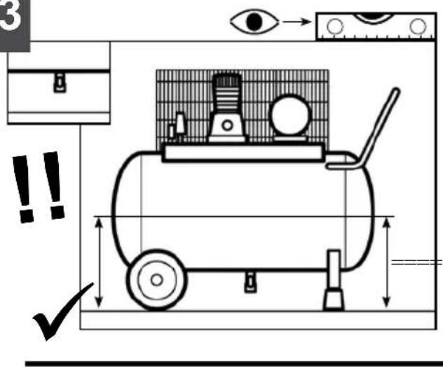
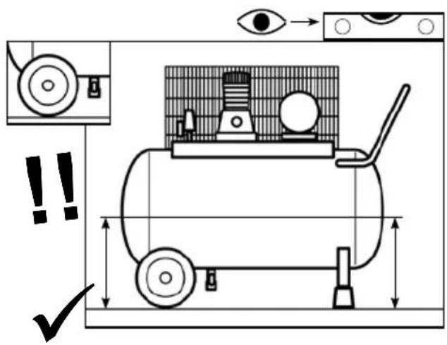
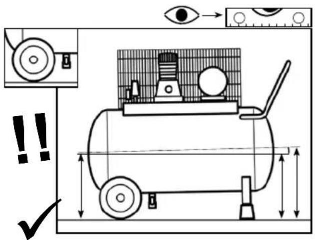
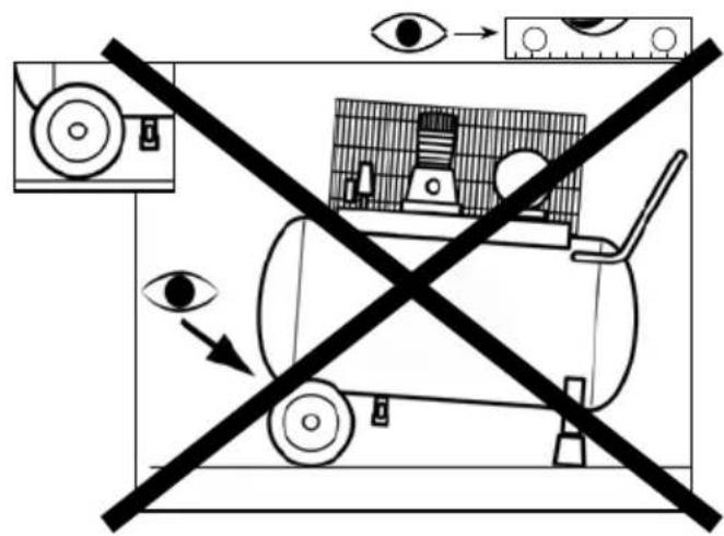
- When operating, the compressor must be placed on a stable, horizontal surface to guarantee correct lubrication, see Section A3.
- Position the compressor at least 50 cm from the wall to permit optimal circulation of fresh air and to guarantee correct cooling.
THINGS NOT TO DO
- Never direct the jet of air towards persons, animals or your body. (Always wear safety goggles to protect your eyes from flying objects that may be lifted by the jet).
- Never direct the jet of liquids sprayed by tools connected to the compressor towards the compressor.
- Never use the appliance in your bare feet or with wet hands or feet.
- Never pull the power cable to pull the plug out of the socket or to move the compressor.
- Never leave the appliance exposed to adverse weather conditions (rain, sun, fog, snow).
- Never transport the compressor with the reservoir pressurized
- Never weld or machine the reservoir. In the case of faults or corrosion, replace it completely.
- Do not tamper with the safety valve.
- Never allow inexpert persons to use the compressor. Keep children and
2 START-UP AND USE
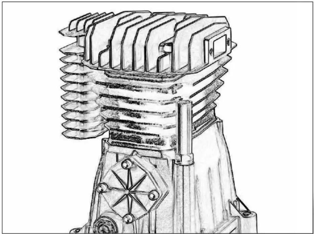
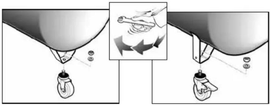
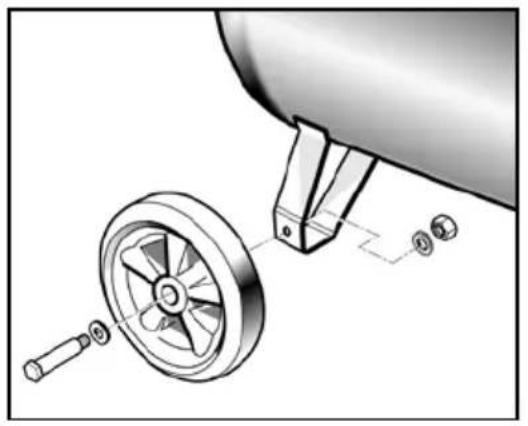
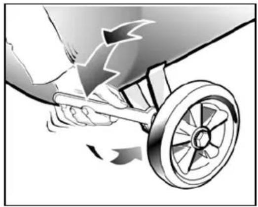
- Assemble the wheels (18) and the foot (16), or the swivel wheel (17) for models on which it is featured; see Section A1-A2. For the versions with fixed feet, assemble the front clamp kit or the vibration dampers, if included.
- Check for correspondence between the compressor plate data with the actual specifications of the electrical system. A variation of ± 10% with respect of the rated value is allowed.
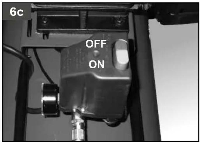
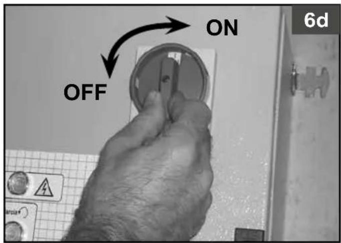
- Insert the power plug in a suitable socket checking that the button of the pressure switch (5) located on the compressor is in the "O" (OFF) position (figures 6a-6b-6c-6d).
- For the 3-phase versions, connect the plug to a panel protected by suitable fuses.
- For the versions fitted with electric panel (20) ("Tandem" control units or delta/star starters, type B, E) have installation and connections (to the motor, to the pressure switch and to the electrovalve if any) carried out by qualified personnel.
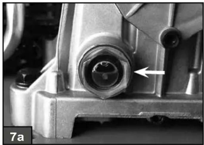
- Check the oil level through the spy-hole (9) (figures 7a-7b) and if need be, top up the oil by unscrewing the breather plug (fig. 7c), after having disassembled the plastic protection (15) in the case of compressors type F
animals away from the work area.
- Never position flammable or nylon or fabric articles close to and/or on the compressor.
- Never clean the compressor with flammable liquids or solvents. Clean with a damp cloth only, after making sure that you have unplugged the compressor.
- The compressor is designed only to compress air and must not be used for any other type of gas.
- The compressed air produced by the compressor cannot not be used for pharmaceutical, food or hospital purposes except after particular treatments. It is not suitable for filling the air bottles of scuba divers.
- Never use the compressor without guards (belt guard) and never touch moving parts.
- Do not touch the parts marked with this symbol (Section A), which indicates components that reach high temperatures during operation and maintain a high temperature for some time after a machine stop.
THINGS YOU SHOULD KNOW
- This compressor is built to operate with an intermittence ratio specified on the motor's rating plate (for example, S3-50 means 5 minutes ON and 5 minutes OFF). In the case of overheating, the thermal cutout of the motor trips, automatically cutting off the power when the temperature is too high due to excess current take-off.
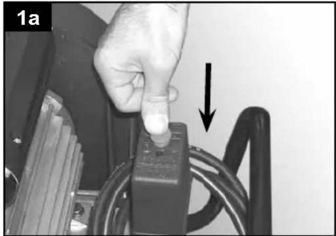
To facilitate machine restart, it is important not only to carry out the operations indicated but also to set the button of the pressure switch (5), returning this to the OFF position and then ON again (figures 1a-1b-3a).
On single-phase versions, press the reset button on the terminal box of the motor (fig. 2).
On 3-phase versions, operate manually on the button of the pressure switch, returning this to the ON position, or press the button of the thermal cutout inside the box of the electric panel (figures 3a-3b-3c).
On the two-stage, three-phase versions with power greater than or equal to 7.5 HP, 220V, and on those with power greater than or equal to 10 HP, 400V, the operator must work the motor protector reset button (fig. 3d) and then bring the pressure switch back to position ON (figg. 6a-6b-6c-6d).
- The single-phase versions are fitted with a pressure (5) switch equipped with a delayed closing air vent valve (or with a valve located on the check valve) that facilitates motor start-up (3); therefore a few-second jet of air from this, with the reservoir empty, is to be considered normal.
- To guarantee machine safety, all the compressors are fitted with a safety valve that is activated in the case of failure of the pressure switch (fig. 4).
- All two-stage compressors are equipped with safety valves (14) on the air delivery manifold to the reservoir and on the connection hose between the low and high pressure located on the head. These are activated in the case of malfunctioning (fig. 5a, 5b).
- When connecting an air-powered tool to a hose of compressed air supplied by the compressor, interruption of the flow of air from the hose is compulsory.
- Multiple accessories and pneumatic tools can be applied to the compressor: for instructions for use, please refer to their respective manuals.
- Use of the compressed air for the various purposes envisaged (inflation, air-powered tools, painting, washing with water-based detergents only, etc.) requires knowledge of and compliance with the rules established for each individual use.
and G (figg. 11a-11c, 12a-12f).
- At this point, the compressor is ready for use.
- Operating on the switch of the pressure switch (5) (or the selector for versions with electric panel, (figures 6a-6b-6c-6d), the compressor starts, pumping air in the reservoir through the delivery hose. On 2-stage versions, air is sucked in to the so-called low pressure cylinder liner and precompressed. It is then routed, through the recirculation hose, into the so-called high pressure liner and then into the reservoir. With this work cycle, it is possible to reach higher pressure, with availability of air at 11 bar (15 bar for special machines).
- On reaching maximum operating pressure (5) (factory-set during testing), the compressor stops, venting the excess air present in the head and in the delivery hose through a valve located under the pressure switch (in delta/star versions, through an electrovalve that is activated when the motor stops).
•The absence of pressure in the head facilitates subsequent restart. When air is used, the compressor restarts automatically when the lower calibration value is reached (approx. 2 bar between upper and lower). The pressure inside the reservoir can be checked on the gauge (10) provided (fig. 4). - The compressor continues to operate automatically with this work cycle
until the position of the switch of the pressure switch (5) (or of the selector of the electric panel) figures 6a-6b-6c-6d) is modified. To use the compressor again, wait at least 10 seconds after this has been switched off before restarting.
- In the versions with electric panel, the pressure switch must always be aligned with the I (ON) position.
- In tandem versions (type E), the control unit provided permits use of only one of the two compressor groups (if necessary alternatively) or of both at the same time according to requirements. In this second case, start-up will be differentiated slightly to avoid excessively high current take-off at start-up (timed starting).
- Only the wheel-mounted compressors are fitted with a pressure reducer (in the versions with fixed feet, it is usually installed on the use line). Air pressure can be regulated in order to optimize use of air-powered tools operating on the knob with the valve open (pulling it up and turning it in a clockwise direction to increase pressure and counterclockwise to reduce this) (fig. 8). Once you have set the value required, push the knob down to lock it.
- The value set can be checked on the gauge (for versions equipped with this, fig. 9).
- Please check that the air consumption and the maximum working pressure of the pneumatic tool to be used are compatible with the pressure set on the pressure regulator and with the amount of air supplied by the compressor.
- When you have finished working, stop the machine, pull out the plug and empty the reservoir.
3 AIR RECEIVER (ON TANK-MOUNTED UNITS)
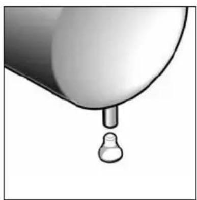
- It is necessary to prevent rust formation: depending on the conditions of use, condensation may accumulate inside the tank (1) and must be discharged daily. This may be done manually, by opening the drain valve, or by means of the automatic drain, if fitted to the tank (4). Nevertheless, a weekly check of correct functioning of the automatic valve is needed. This has to be done by opening the manual drain valve and check for condensate (fig. 14a, 14b).
- It is necessary to have the thickness of the air tank walls (1) annually checked by a competent body, because corrosion inside the tank may reduce thickness of the steel walls, with the consequential risk of explosions. If applicable, observe the local standards. It is not allowed to use the air tank when wall thickness does not reach the minimum value indicated in the tank certification (part of the documentation delivered with the unit).
- Lifetime of the air receiver (1) mainly depends on the working environment. Avoid installing the compressor in a dirty and corrosive environment, as this can reduce the vessel lifetime dramatically.
- Do not anchor the vessel (1) or attached components directly to the ground or fixed structures. Fit the pressure vessel with vibration dampers to avoid possible fatigue failure caused by vibration of the vessel during use.
- Use the vessel (1) within the pressure and temperature limits stated on the nameplate and the testing report.
- No alterations must be made to this vessel by welding, drilling or other mechanical methods.
4 MAINTENANCE
• The service life of the machine depends on maintenance quality.
- PRIOR TO ANY OPERATION SET THE PRESSURE SWITCH TO THE OFF POSITION, PULL OUT THE PLUG AND COMPLETELY DRAIN THE RESERVOIR.
- Perform service tasks with the machine cold, wearing the personal protective equipment.
Use the equipment that suits each service task and only use original spare parts.
- Check that all screws, in particular those of the head of the unit (2) are tightly drawn up (fig. 10). Check head tightening before the first start up and after the first hour of work.
TABLE 1 – TIGHTENING OF HEAD TENSION RODS
| NmMin. torque | NmMax. torque | |
| Screw M6 9 11 | ||
| Screw M8 22 27 | ||
| Screw M10 45 55 | ||
| Screw M12 76 93 | ||
| Screw M14 121 148 |
- To perform the main service tasks on type F compressors, disassemble the plastic protection (15) (figures 11a-11c). When you are finished with the service task, reassemble the plastic protection, following the reverse procedure.
- To perform the main service tasks on type G compressors, disassemble the plastic protection (15) (fiures 12a-12f), removing the front semi-shell first and then the rear one. When you are finished with the service task, reassemble the plastic protection, following the reverse procedure.
- Clean the suction filter (13) according to the type of environment and in any case at least every 100 hours. If necessary, replace the filter (a clogged filter impairs efficiency while an inefficient filter causes harsher wear on the compressor (figures 13a - 13b).
- Change the oil after the first 100 hours of operation and subsequently every 500 hours. Check the oil level periodically (9).
- Use ALTAIR. Never mix different grade oils. If the oil changes color (whitish = presence of water; dark = overheated), it is good practice to replace the oil immediately.
- After topping up (8), tighten the plug (fig. 7c) making sure that there are no leaks during use. Once a week, check the oil level to assure lubrication in time (fig. 7a, 7b).
- Periodically, check the tension of the belts which must have a flexion (f) of around 1 cm (fig. 15).
| FUNCTION | AFTER THE FIRST 100 HOURS | EVERY 100 HOURS | EVERY 500 HOURS |
| Cleaning of intake filter and/or substitution of filtering element | ● | ||
| Change of oil* | ● | ● | |
| Tightening of head tension rods | Check head tightening before the first start up and after the first hour of work | ||
| Draining tank condensate Daily | |||
| Checking the tension of the belts | Periodically | ||
| Air tank wall thickness inspection. | Annually | ||
*Spent oil and condensate MUST BE DISPOSED OF in compliance with protection of the environment and current legislation.
The compressor must be disposed in conformity with the methods provided for by local regulations
5 POSSIBLE FAULTS AND RELATED PERMITTED REMEDIES
Request the assistance of a qualified electrician for operations on electric components (cables, motor, pressure switch, electric panel, etc).
| FAULT | CAUSE | REMEDY |
| Air leak from the valve of the pressure switch. | Check valve does not perform its function correctly due to wear or dirt on the seal. | Unscrew the hex-shaped head of the check valve, clean the housing and the special rubber disk (replace if worn). Re-assembler and tighten carefully (figures 16a-16b). |
| Condensate drainage cock (4) open. | Close the Condensate drainage cock. | |
| Rilsan hose not inserted correctly in pressure switch. | Insert the Rilsan hose correctly inside the pressure switch (fig. 17). | |
| FAULT CAUSE REMEDY | ||
| Reduction of efficiency, frequent start-up. Low pressure values. | Excessively high consumption. | Decrease the demand of compressed air. |
| Leaks from joints and/or pipes. | Change gaskets. | |
| Clogging of the suction filter. | Clean/replace the suction filter (13) (figures 13a-13b). | |
| Slipping of the belt. Check belt tension (fig. 15). | ||
| The motor (3) and/or the compressor overheat irregularly. | Insufficient ventilation. Improve ambient conditions. | |
| Closing of air ducts. Check and if necessary clean the air filter (13). | ||
| Insufficient lubrication. | Top up or change oil (figures 18a-18b-18c-18d). | |
| After an attempt to start the compressor, it stops due to tripping of the thermal cutout caused by forcing of the motor. | Start-up with head of the compressor charged. | Release the compressor head by using the pressure switch push button (5). |
| Low temperature. Improve ambient conditions. | ||
| Voltage too low. | Check that the mains voltage matches that of the dataplate. Eliminate any extensions. | |
| After an attempt to start the compressor, it stops due to tripping of the thermal cutout caused by forcing of the motor. | Incorrect or insufficient lubrication. | Check level (9), top up and if necessary change the oil. |
| Inefficient electrovalve. Call the Service Center. | ||
| During operation, the compressor stops for no apparent reason. | Tripping of the thermal cutout of the motor. | Check level oil (9). |
| Single-stage, mono-phase versions: operate on the button of the pressure switch (5) returning this to the OFF position (fig. 1a). Reset the thermal cutout (fig. 2) and restart (figures 1b). If the fault persists, call the Service Center. | ||
| Versions with delta-star starter: operate on the button of the thermal cutout located inside the box of the electric panel (20) (fig. 3c) and restart (fig. 6d). If the fault persists, call the Service Center. | ||
| Two-stage, three-phase versions with power greater than or equal to 7.5 HP, 220V, Two-stage, three-phase versions with power greater than or equal to 10 HP, 400V: work the motor protector reset button (fig. 3d), to bring the pressure switch back into position ON (figures. 6a-6b-6c-6d). | ||
| Other versions: Operate on the button of the pressure switch (5) returning this to the OFF position and then to ON again (fig. 1a-1b). If the fault persists, call the Service Center. | ||
| Electric fault. Call the Service Center. | ||
| When operating, the compressor vibrates and the motor emits an irregular buzzing sound. If it stops, it does not restart although the sound of the motor is present. | Single-phase motors: faulty capacitor. | Have the capacitor replaced. |
| 3-phase motors: One of the phases of the 3-phase power supply is missing due probably to blowing of a fuse. | Check the fuses inside the electric panel or the electric box (20) and if necessary replace those that have been damaged (fig. 19). | |
| Irregular presence of oil in the network. | Too much oil inside the unit. Check oil level (9). | |
| Wear on segments. Call the Service Center. | ||
| Leaking of condensate from the vent cock (4). | Presence of dirt/grit inside the cock. | Clean the cock. |
Any other type of operation must be carried out by authorized Service Centers, requesting original parts. Tampering with the machine may impair its safety and in any case make the warranty null and void.
1 PRECAUTIONS D'UTILISATION

A FAIRE
5 POSSIBLES ANOMALIES ET INTERVENTIONS ADMISES
3 LUFTBEHOLDER (PÅ BEHOLDERMONTEREDE ENHEDER)
(slike 11a-11c, 12a-12f).
- U ovom trenutku kompresor je spreman za upotrebu.
- Pritiskom prekidača na tlačnoj sklopki (5) (ili birača za modele s električnom razvodnom pločom, (slike 6a-6b-6c-6d), kompresor se pokreće pumpajući zrak u spremnik kroz izlaznu cijev. Kod dvostupanjskih modela, zrak se usisava u cijev niskotlačnog cilindra i predstlačuje. Zatim se preko obtočne cijevi dovodi u cilindričnu visokotlačnu cijev i nakon toga u spremnik.
u Pomoću ovog radnog ciklusa moguće je postići viši tlak, uz mogućnost isporuke zraka pri tlaku od 11 bara (15 bara za posebne strojeve). - Nakon postizavanja najvećeg radnog tlaka (tvornički podešeno tijekom ispitivanja) kompresor se zaustavlja, ispuštajući prekomjerni zrak koji se nalazi u glavi i izlaznoj cijevi kroz ventil koji se nalazi ispod tlačne sklopke (za zvjezdasto/trokutaste verzije, kroz magnetski ventil koji se aktivira prilikom zaustavljanja motora).
- Nedostatak pretlaka u glavi olakšava slijedeće pokretanje motora. Kada se upotrebljava zrak, kompresor se pokreće automatski kada je postignuta niža podešena vrijednost (razlika između donje i gornje vrijednosti je otprilike 2 bara).
Tlak unutar tlačne posude može se provjeravati na isporučenom manometru (10) (slika 4).
- Kompresor automatski nastavlja rad s ovim radnim ciklusom dok se ne
TABELL 1 – STRAMMING AV HOLDER FOR MUNNSTYKKET
| NmMin. moment | NmMaks. moment | |
| Bolt M6 9 11 | ||
| Bolt M8 22 27 | ||
| Bolt M10 45 55 | ||
| Bolt M12 76 93 | ||
| Bolt M14 121 148 |
TABELL 2 – VEDLIKEHOLDSINTERVALLER
natural_image
Symbol of a trash bin crossed out by a diagonal line, representing no waste or discharge (no text present)


- Belt driven piston compressor
- Section B
- Preserve this handbook for future reference
- PRECAUTIONS
- THINGS TO DO
- THINGS NOT TO DO
- START-UP AND USE
- THINGS YOU SHOULD KNOW
- AIR RECEIVER (ON TANK-MOUNTED UNITS)
- MAINTENANCE
- POSSIBLE FAULTS AND RELATED PERMITTED REMEDIES
- PRECAUTIONS D'UTILISATION
- A FAIRE
- POSSIBLES ANOMALIES ET INTERVENTIONS ADMISES
- LUFTBEHOLDER (PÅ BEHOLDERMONTEREDE ENHEDER)
Brand : Abac
Model : A29B 90 CM3
Category : Compressor