
B3501050 - Compressor STANLEY - Free user manual and instructions
Find the device manual for free B3501050 STANLEY in PDF.
| Product type | Air compressor |
| Brand | STANLEY |
| Model | B3501050 |
| Tank capacity | 50 liters |
| Maximum pressure | 10 bar (145 PSI) |
| Cut-in pressure | 8 bar |
| Cut-out pressure | 10 bar |
| Motor type | Single-phase 230 V |
| Frequency | 50 Hz |
| Weight | 35 kg |
| Oil type | SAE 15W/40 |
| Number of wheels | 2 |
| Transport handle | Yes |
| Safety valve | Yes, factory set |
| Air filter | Yes, clean every 100 hours |
| Condensate drain | Daily |
| Thermal protection | Yes |
| On/off switch | Yes |
| Applications | Inflation, painting, pneumatic tools, washing |
| Compliance | CE |
Frequently Asked Questions - B3501050 STANLEY
User questions about B3501050 STANLEY
0 question about this device. Answer the ones you know or ask your own.
Ask a new question about this device
Download the instructions for your Compressor in PDF format for free! Find your manual B3501050 - STANLEY and take your electronic device back in hand. On this page are published all the documents necessary for the use of your device. B3501050 by STANLEY.
USER MANUAL B3501050 STANLEY
STANLEY, The STANLEY Logo, The Notched Rectangle and the
Yellow and Black Diagonal Package Design are all trademarks of
Stanley Black & Decker, Inc or an affiliate thereof and are used under license.
Product manufactured and distributed by:
FNA S.p.A. - Via Einaudi 6, Robassomero (TO) Italy.
Attenzione! - Warning! - Attention! - Achtung! - ¡Cuidado! - Atenção! - Waarschuwing! - Advarsel! - Varning! - Varoitus! - Прогохή! - Uwaga! - Pozor! - Pozor! - Figyelem! - Pozor! - Pozor! - Внимание! - Advarsel! - Uyari! - Atenție! - Внимание! - Pažnja! - Dėmesio! - Tähelepanu! - Uzmanību!
IT Tutti i dati identificativi, costruttore, modello, codice e numero di serie, sono riportati sull'etichetta CE applicata sull'ultima pagina del manuale.
GB All identification data: manufacturer, model, code and serial number are printed on EC label stuck onto the last page of this manual.
FR Toutes les données d'identification : fabricant, modèle, référence et numéro de série, sont indiquées sur l'étiquette CE appliquée sur la dernière page du manuel.
DE Sämtliche Gerätedaten wie Hersteller, Modell, Artikel- und Seriennummer sind auf der CE-Plakette angeführt, die auf der letzten Seite des Handbuchs abgebildet ist.
ES Todos los datos identificativos: fabricante, modelo, código y número de serie figuran en la etiqueta CE aplicada en la última página del manual.
PT Todos os dados de identificação: fabricante, modelo, código e número de série são impressos na etiqueta CE colada na última página deste manual.
NL Alle identificatiegegevens: fabrikant, model, code en serienummer zijn gedrukt op het EG-etiket dat is aangebracht op de laatste pagina van deze handleiding.
DK Alle identifikationsoplysninger: Producent, model, kode og serienummer findes på CE-mærkaten, der er anbragt på sidste side i denne manual.
SE Alla identifieringsdata, tillverkare, modell, kod och serienummer, återges i CE-märkningen, som sitter på sista sidan i manualen.
FI Kaikki tunnistustiedot, kuten valmistaja, malli, koodi ja sarjanumero löytyvät oppaan viimeisellä sivulla olevasta CE-merkinnästä.
GR Όλα τα στοιχεία ταυτότητας, κατασκευαστής, μοντέλο, κωδικός, και αριθμός σειράς, αναφέρονται στην ετικέτα CE που βρίσκεται στην τελευταία σελίδα του εγχειρίδιου χρήσης.
PL Wszystkie dane identyfikacyjne: producent, model, kod i numer seryjny zostały wskazane na oznaczeniu CE przyklejonym na ostatniej stronie niniejszej instrukcji.
HR Svi identifikacijski podaci: proizvođač, model, šifra i serijski broj su ispisani na CE etiketi koja se nalazi na posljednjoj stranici ovog priručnika.
SI Vsi identifikacijski podatki, proizvajalec, model, koda in serijska številka, so navedeni na CE oznaki, ki se nahaja na zadnji strani priročnika.
HU Az azonosításhoz szükséges adatok, úgymint gyártó, modell, kód és sorozatszám, megtalálhatók a kézikönyv utolsó oldalára ragasztott EK-címkén.
Všechny identifikační údaje (výrobce, model, kód a sériové číslo) jsou vytištěny na štítku EK nalepeném na poslední straně této příručky.
SK Všetky identifikačné údaje (výrobca, model, kód a sériové číslo) sú vytlačené na štítku EK nalepenom na poslednej strane tejto príručky.
RU Все идентификационные данные, название производителя, модель, номер и серийный номер указаны на этикетке CE, наклеенной на последней странице руководства.
NO Alle identifikasjonsdata: Produsent, modell, kode og serienummer er trykt på EU-merket som du finner på den siste siden i denne bruksanvisningen.
TR Tüm kimlik verileri: üretici, model, kod ve seri numarası, bu kılavuzun son sayfasına yapıştırılmış olan AT etiketi üzerine basılmıştır.
RO Toate datele de identificare, producătorul, modelul, codul și numărul de serie sunt redate pe eticheta CE aplicată pe ultima pagină a manualului.
BG Всички идентификационни данни - производител, модел, код и сериен номер - са отпечатани върху СЕ маркировката на последната страница на настоящото ръководство.
RS Svi identifikacijski podaci: proizvođač, model, šifra i serijski broj su ispisani na CE etiketi koja se nakazi na zadnjoj strani ovog priručnika.
LT Visi identifikaciniai duomenys: gamintojas, modelis, kodas ir serijos numeris, yra išspausdinti EB etiketėje, priklijuotoje paskutiniame šio vadovo puslapyje.
EE Kõik identifitseerimisandmed, nagu tootja, mudel, kood ja seerianumber, on trükitud toote tagaküljel olevale EÜ märgistusele.
LV Visi identifikacijas dati: ražotājs, modelis, kods un sērijas numurs ir drukāti uz EK etiketes, kas pielīmēta šīs rokasgrāmatas pēdējā lapā.
Dichiarazione di conformità CE - Declaration of compliance EEC - Déclaration de conformité CE - EG Konformitätserklärung - Declaración de conformidad CE - Declaração de conformidade CE - Verklaring van overeenstemming EEG - CE-Overensstemmelseserklæring - Försäkran om CE-överensstämmelse - CE Vaatimustenmukaisuusvakuutus - Δηλωση συμμορφωσης CE - Deklaracja zgodności WE - Izjava o sukladnosti direktivama EZ - Izjava o skladnosti ES - EK Megfelelési nyilatkozat - ES Prohlášení o shodě - Prehlásenie ES o zhode - Декларация о соответствии нормам EO - EF-overensstemmelseserklæring - AT uygunluk beyani - Declarație de conformitate CE - Декларация за съответствие по стандарт на EO - Izjava o sukladnosti propisima EZ - Deklaracija dėl EB reikalavimų vykdymų - Vastavusdeklaratsioon EK - Paziņojums par atbilstību EK prasībām
IT La seguente dichiarazione è allegata in copia originale al compressore.
GB The following declaration is attached to the compressor in original copy.
FR La déclaration suivante est jointe en copie originale au compresseur.
DE Die gegenständliche Erklärung wird im Original dem Kompressor beigepackt.
ES La siguiente declaración se adjunta en copia original al compresor.
PT A seguinte declaração está anexada ao compressor na cópia original.
NL Een originele kopie van de onderhavige verklaring is bij de compressor gevoegd.
DK Denne erklæring vedlægges kompressoren i førsteeksemplar.
SE Följande försäkran bifogas kompressorn i originalkopia.
FI Seuraava vakuutus on liitetty kompressoriin alkuperäisenä kopiona.
GR Αυθεντικό αντίτυπο της παρακάτω δήλωσης προσαρτάται στον συμπιεστή.
PL Oryginał niniejszej deklaracji jest dołączony do sprężarki.
HR Uz kompresor je priložena kopija originala sljedeće izjave.
SI Ta izjava je v originalu priložena kompresorju.
HU Az alábbi nyilatkozat eredeti példánya a kompresszor mellékletét képezi.
CZ Následující prohlášení je přiloženo ke kompresoru v originální kopii.
SK Nasledujúce vyhlásenie je priložené ku kompresoru v originálnej kópii.
RU Оригинал декларации прилагается к компрессору.
NO Den følgende erklæringen er festet til kompressoren i original kopi.
TR Aşağıdaki beyan, orijinal nüsha olarak kompresöre iliştirilmiştir.
RO Următoarea declarație este anexată în copie originală la compresor.
BG Оригинално копие на следната декларация е прикрепена към компресора.
RS Uz kompresor je priložena kopija originala sledeće izjave.
LT Toliau pateiktos deklaracijos originali kopija pritvirtinta prie kompresoriaus.
EE Selle avalduse originaaleksemplar on kinnitatud kompressorile.
LV Sekojošas deklaracijas originālā kopija ir pievienota kompresoram.
Il costruttore - The manufacturer - Le fabricant - der Hersteller - El fabricante - O fabricante - De fabrikant - Producent - Tillverkare - Valmistaja - O kataoškeuostnč - Producent - Proizvođač - Proizvajalec - A gyártó - Výrobce - Výrobca - Производителя - Produsent - Üretici - Producătorul - Производител - Proizvođač - Gamintojas - Tootja - Ražotājs
| IT | Dichiara sotto la sua esclusiva responsabilità, che il compressore d'aria qui di seguito descritto è conforme alle prescrizioni di sicurezza delle direttive applicabili. |
| GB | Declares under its sole responsibility that the air compressor described below complies with the safety requirements of applicable directives. |
| FRDE | Déclare sous son entière responsabilité que le compresseur d'air décrit ci-après est conforme aux prescriptions de sécurité des directives applicables.Erklärt unter ihrer alleinigen Verantwortung, dass der in Folge beschriebene Luftkompressor den Sicherheitsvorschriften der anwendbaren Richtlinien entspricht. |
| ES | Declara, bajo su exclusiva responsabilidad, que el compresor de aire descrito a continuación responde a las prescripciones de seguridad de las directivas aplicables. |
| PT | Declara sob a sua exclusiva responsabilidade que o compressor de ar descrito a seguir está em conformidade com as prescrições de segurança das directivas aplicáveis. |
| NL | Verklaart onder zijn eigen verantwoordelijkheid dat de hieronder beschreven persluchtcompressor in overeenstemming is met de veiligheidsvoorschriften die van toepassing zijn. |
| DK | Erklærer under eget ansvar, at luftkompressoren, der beskrives nedenfor, er i overensstemmelse med sikkerhedsforskrifterne i direktiverne. |
| SE | Försäkrar under eget ansvar att den luftkompressor som beskrivs nedan överensstämmer med de tillämpliga direktivens säkerhetsföreskrifter. |
| FI | Vakuuttaa omalla vastuullaan, että seuraavassa esitelty ilmakompressori vastaa sovellettavien direktiivien turvallisuusvaatimuksia. |
| GR | Δηλώνει με αποκλειστική δική της ευθύνη, ότι ο συμπιεστής αέρος που περιγράφεται παρακάτω ανταποκρίνεται στις προδιαγραφές ασφαλείας των οδηγιών που ισχύουν. |
| PL | Oświadczenie na swoją wyłącznie odpowiedzialność, że opisana poniżej sprężarka spełnia wymagania w zakresie bezpieczeństwa zawarte w obowiązujących dyrektywach. |
| HR | Izjavljuje pod vlastitom odgovorność da dolje opisani kompresor zraka udovoljava svim sigurnosnim zahtjevima važećih Direktiva. |
| SI | Izjavlja pod lastno odgovornostjo, da je v nadaljevanju opisan kompresor za zrak skladen z varnostnimi določili dozadevnih direktiv. |
| HU | Saját felelőssége tudatában kijelenti, hogy a lent megnevezett kompresszor megfelel a vonatkozó irányelvek biztonsági követelményeinek. |
| CZ | Prohlašuje s plnou odpovědností, že uvedený vzduchový kompresor vyhovuje bezpečnostním požadavkům příslušných směrnic. |
| SK | Vyhlasuje na vlastnú zodpovednosť, že uvedený vzduchový kompresor vyhovuje bezpečnostným požiadavkám příslušných smerníc. |
| RU | Заявляет под свою исключительную ответственность, что воздушный компрессор, описанный ниже, отвечает всем требованиям безопасности применяемых директив. |
| NO | Erklærer under eget ansvar at luftkompressoren her beskrevet er i overensstemmelse med sikkerhetsforskriftene i de gjeldende direktivene. |
| TR | Tek sorumluluk kendisinde olmak üzere, aşağıda açıklanan hava kompresörünün, geçerli direktiflerin güvenlik gereklerine uygun olduğunu beyan eder. |
| RO | Declará pe propria răspundere că compresorul de aer descris în continuare este conform cu cerințele de siguranță ale directivelor aplicabile. |
| BG | Декларира на собствена отговорност, че описаният по-долу въздушен компресор е в съответствие с изискванията на приложимите директиви за безопасност. |
| RS | Izjavljuje pod ličnom odgovornošću da je dole opisan kompresor vazduha u skladu sa svim zahtevima bezbednosti koje propisuju važeće Direktive. |
| LT | Su visa atsakomybe pareiškia, kad žemiau aprašytas oro kompresorius atitinka taikomų direktyvų saugos reikalavimus. |
| EE | Avaldab enda täieliku vastutusega, et järgnevalt kirjeldatud ōhukompressor vastab kohaldatavate direktiivide ohutusnõuetele. |
| LV | Pilnîbā apstiprina, ka tâlāk minētais gaisa kompresors atbilst piemērojamo direktīvu drošības prasībām. |
IT LEGENDA SEGNALETICA DI SICUREZZA SUI PRODOTTI
GB KEY TO PRODUCT SAFETY SIGNS
FR LEGENDE DES PICTOGRAMMES DE SECURITE FIGURANT SUR LES PRODUITS
NL VERKLARING WAARSCHUWINGSSYMBOLEN OP PRODUCTEN
DK SIGNATURFORKLARING TIL PRODUKTERNES SIKKERHEDSSKILTNING
SE FÖRKLARING TILL SÄKERHETSSYMBOLER PÅ PRODUKTERNA
GB Before use, read the handbook carefully
GB Warning, hot surfaces
GB Danger - automatic control (closed loop)
GB Hearing, eye and respiratory protection must be worn
GB Preserve this handbook for future reference
GB TECHNICAL DATA: Please, refer to the label stuck onto the last page of this manual
1 - Manufacturer's data
2 - CE mark and WEEE symbol
3 - Type / Code / Serial Number
4 - Air displacement expressed in (l/min) and (cfm)
5 - Air delivered by the compressor expressed in (l/min) and (cfm)
6 - Maximum operating pressure (bar and PSI), tank capacity (l), rotations per minute (RPM), weight (kg)
7 - Guaranteed sound power level in dB(A); Measured sound power level in dB(A)
8 - Electric data: voltage (V), frequency (Hz), absorption (A), power in (kW) and (HP)
9 - Duty cycle
10 - Declaration of origin
11 - Year of production/manufacturing
FR Légende
2c
3

4
5
6

7


natural_image
Technical illustration of a mechanical fan or compressor with airflow arrows indicating motion (no text or symbols)
natural_image
Technical illustration of an electric motor connected to a pulley system with directional arrows indicating motion (no text or symbols)

natural_image
Illustration of a hand using a tool to adjust a mechanical component (no text or symbols visible)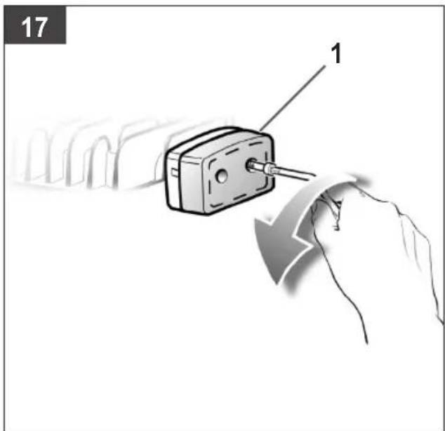
natural_image
Illustration of three mechanical components with threaded connectors, shown in open and assembled views (no text or symbols)

natural_image
Illustration of a hand using a wrench to adjust or install a mechanical component (no text or symbols visible)
natural_image
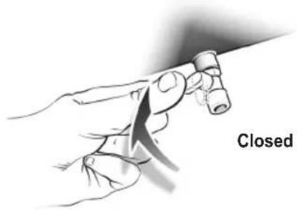
Illustration of a hand holding a connector with tubing, no text or symbols present
natural_image
Hand inserting a switch into an electrical fuse (no text or symbols visible)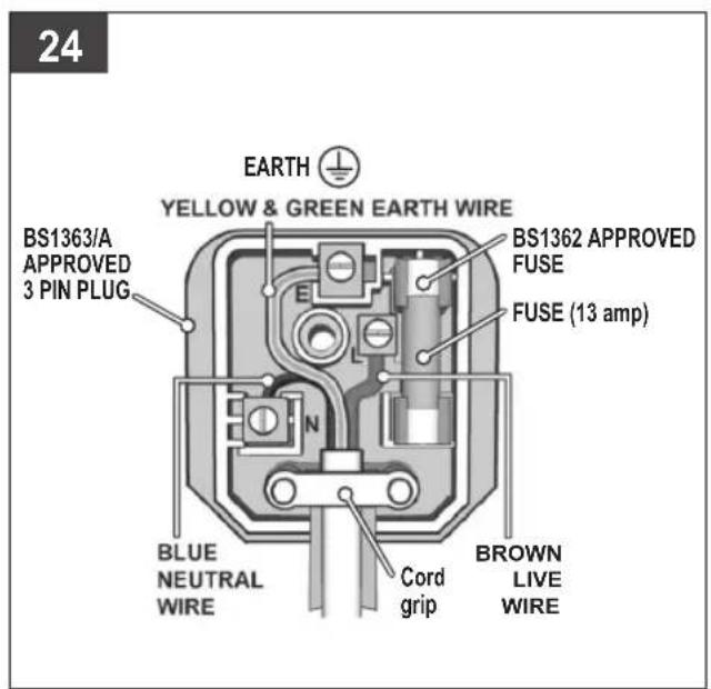
Preserve this handbook for future reference
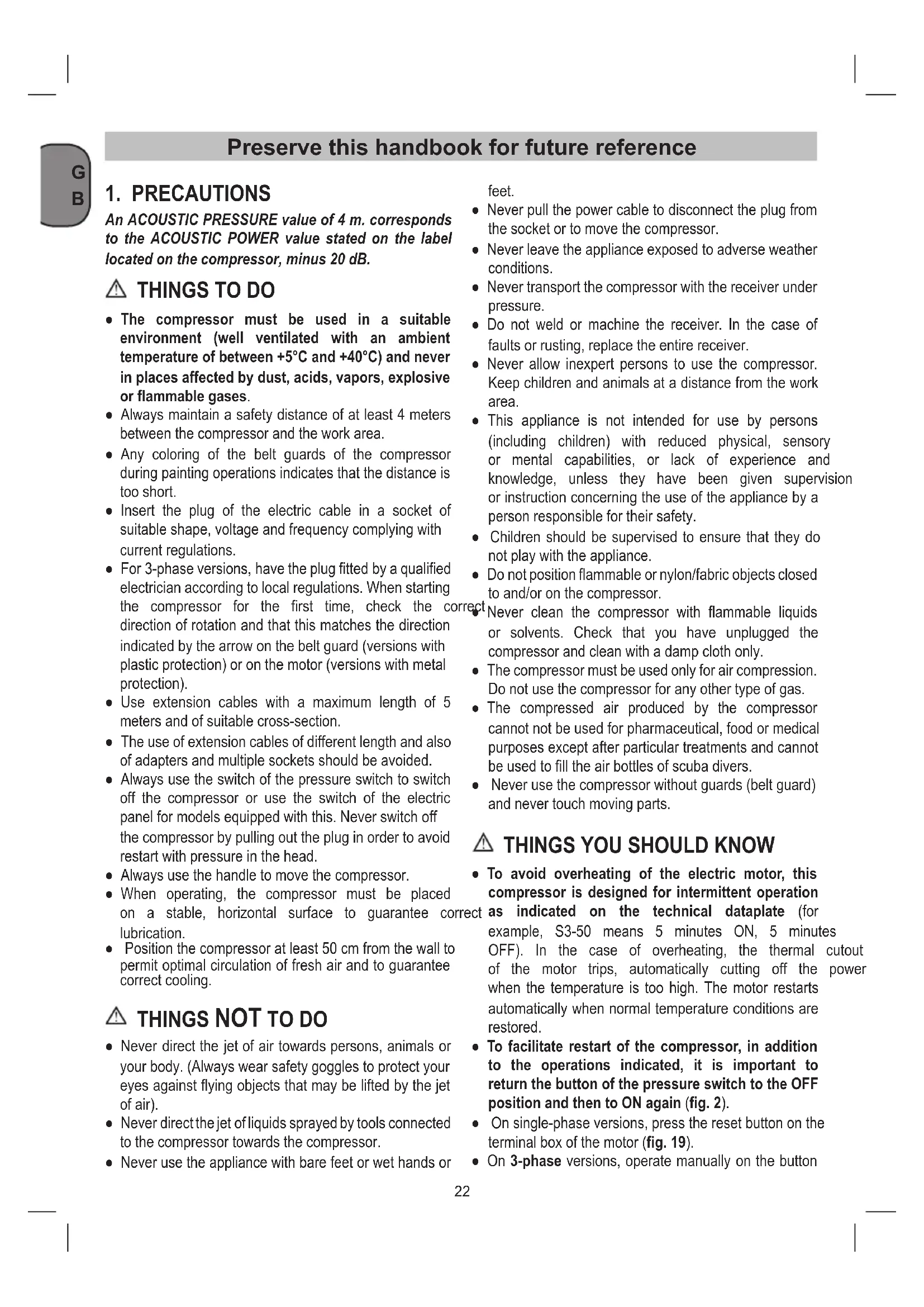
1. PRECAUTIONS
An ACOUSTIC PRESSURE value of 4 m. corresponds to the ACOUSTIC POWER value stated on the label located on the compressor, minus 20 dB.
▲ THINGS TO DO
- The compressor must be used in a suitable environment (well ventilated with an ambient temperature of between +5°C and +40°C) and never in places affected by dust, acids, vapors, explosive or flammable gases.
- Always maintain a safety distance of at least 4 meters between the compressor and the work area.
- Any coloring of the belt guards of the compressor during painting operations indicates that the distance is too short.
- Insert the plug of the electric cable in a socket of suitable shape, voltage and frequency complying with current regulations.
- For 3-phase versions, have the plug fitted by a qualified electrician according to local regulations. When starting the compressor for the first time, check the co-direction of rotation and that this matches the direction indicated by the arrow on the belt guard (versions with plastic protection) or on the motor (versions with metal protection).
- Use extension cables with a maximum length of 5 meters and of suitable cross-section.
- The use of extension cables of different length and also of adapters and multiple sockets should be avoided.
- Always use the switch of the pressure switch to switch off the compressor or use the switch of the electric panel for models equipped with this. Never switch off the compressor by pulling out the plug in order to avoid restart with pressure in the head.
- Always use the handle to move the compressor.
- When operating, the compressor must be placed on a stable, horizontal surface to guarantee correct lubrication.
- Position the compressor at least 50 cm from the wall to permit optimal circulation of fresh air and to guarantee correct cooling.
▲ THINGS NOT TO DO
- Never direct the jet of air towards persons, animals or your body. (Always wear safety goggles to protect your eyes against flying objects that may be lifted by the jet of air).
- Never direct the jet of liquids sprayed by tools connected to the compressor towards the compressor.
- Never use the appliance with bare feet or wet hands or
feet.
- Never pull the power cable to disconnect the plug from the socket or to move the compressor.
- Never leave the appliance exposed to adverse weather conditions.
- Never transport the compressor with the receiver under pressure.
- Do not weld or machine the receiver. In the case of faults or rusting, replace the entire receiver.
- Never allow inexpert persons to use the compressor. Keep children and animals at a distance from the work area.
- This appliance is not intended for use by persons (including children) with reduced physical, sensory or mental capabilities, or lack of experience and knowledge, unless they have been given supervision or instruction concerning the use of the appliance by a person responsible for their safety.
- Children should be supervised to ensure that they do not play with the appliance.
- Do not position flammable or nylon/fabric objects closed to and/or on the compressor.
Never clean the compressor with flammable liquids or solvents. Check that you have unplugged the compressor and clean with a damp cloth only.
- The compressor must be used only for air compression. Do not use the compressor for any other type of gas.
- The compressed air produced by the compressor cannot not be used for pharmaceutical, food or medical purposes except after particular treatments and cannot be used to fill the air bottles of scuba divers.
- Never use the compressor without guards (belt guard) and never touch moving parts.
▲ THINGS YOU SHOULD KNOW
- To avoid overheating of the electric motor, this compressor is designed for intermittent operation except as indicated on the technical dataplate (for example, S3-50 means 5 minutes ON, 5 minutes OFF). In the case of overheating, the thermal cutout of the motor trips, automatically cutting off the power when the temperature is too high. The motor restarts automatically when normal temperature conditions are restored.
- To facilitate restart of the compressor, in addition to the operations indicated, it is important to return the button of the pressure switch to the OFF position and then to ON again (fig. 2).
- On single-phase versions, press the reset button on the terminal box of the motor (fig. 19).
- On 3-phase versions, operate manually on the button
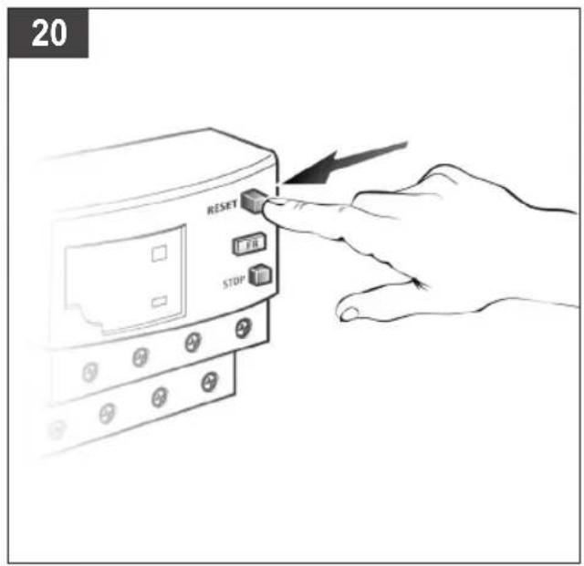
of the pressure switch, returning this to the ON position, or press the button of the thermal cutout inside the box of the electric panel (figures 2b & 20).
- The single-phase versions are fitted with a pressure switch equipped with a delayed closing air vent valve (or with a valve located on the check valve) that facilitates motor start-up; therefore a few-second jet of air this, with the reservoir empty, is to be considered normal.
- To guarantee machine safety, all the compressors are fitted with a safety valve that is activated in the case of failure of the pressure switch.
The safety valve is set to avoid over-pressurization of the air tanks. This valve is factory pre-set and will not function unless tank pressure reaches this pressure. Do not attempt to adjust or eliminate this safety device.
Any adjustments to this valve could cause serious injury. If this device requires service or maintenance, see an Authorized Service Center.
- The red notch on the pressure gauge refers to the maximum operating pressure of the tank. It does not refer to the adjusted pressure.
- When fitting a tool, the flow of air in output must be from switched off.
When using compressed air, you must know and comply with the safety precautions to be adopted for each type of application (inflation, pneumatic tools, painting, washing with water-based detergents only, etc.).
- Please check that the air consumption and the maximum working pressure of the pneumatic tool and connection pipes (with the compressor) to be used, are compatible with the pressure set on the pressure regulator and with the amount of air supplied by the compressor.

2. LAYOUT
- Intake air filter
- Pressure vessel
- Wheel
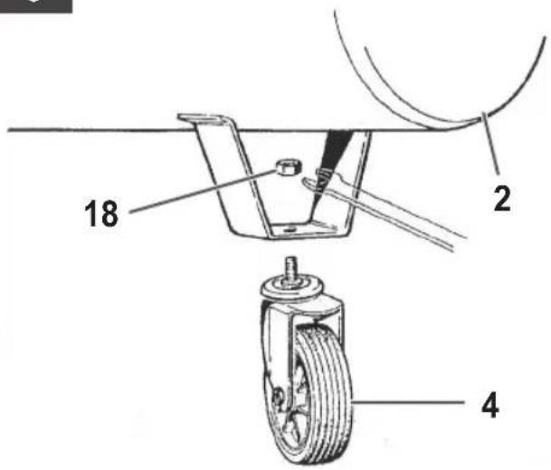
- Caster wheel (or supporting rubber foot)
- Quick-lock coupling (regulated compressed air)
- Pressure gauge (indicates the pressure set by pressure regulator)
- Pressure regulator
- ON/OFF switch
- Transportation handle
- Safety valve
- Drain valve for condensation water
- Pressure gauge (for reading the tank pressure)
- Quick-lock coupling (unregulated compressed air)
- Oil sealing plug (or oil filler opening)
- Oil drainage screw
- Oil level window
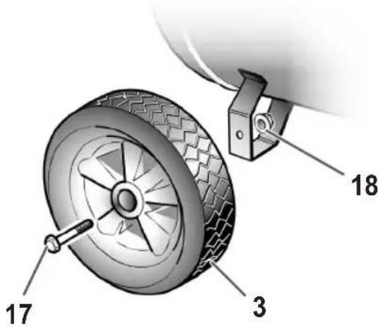
- Bolt
- Nut
- Washer
- Check valve
3. SCOPE OF USE
The compressor is designed for generating compressed air for tools operated by compressed air.
Please note that our equipment has not been done for use in commercial, trade or industrial applications. Our warranty will be voided if the machine is used in commercial, trade or industrial businesses or for equivalent purposes.
The machine is to be used only for its prescribed purpose. Any other use is deemed to be a case of misuse. The user
/ operator and not the manufacturer will be liable for any damage or injuries of any kind caused as a result of this.
4. POINTS TO NOTE WHEN SETTING UP THE COMPRESSOR
- Examine the machine for signs of transit damage. Report any damage immediately to the company which delivered the compressor.
- The compressor should be set up near the working consumer.
- Avoid long air lines and long supply lines (extensions).
• Make sure the intake air is dry and dust-free. - Do not set up the compressor in damp or wet rooms.
- The compressor may only be used in suitable rooms (with good ventilation and an ambient temperature from +5°C to +40°C). There must be no dust, acids, vapors, explosive gases or inflammable gases in the room.
- The compressor is designed to be used in dry rooms. It is prohibited to use the compressor in areas where work is conducted with sprayed water.
- The oil level in the compressor pump has to be checked before putting the equipment into operation.
5. ASSEMBLY AND STARTING
Warning!
You must fully assemble the appliance before using it for the first time.
5.1 Fitting the wheels (Figs. 4-5)
Fit the supplied wheels as shown in figures 4 & 5.
5.1.1 Fitting the supporting foot (only for B 25x/10/50, B 350/10/50, B480/10/50)
Fit the supplied rubber stopper as shown in Fig. 6.
5.2 Fitting the quick-lock coupling for tank pressure (ref. 13)
Screw the quick-lock coupling for unregulated tank pressure (ref. 13) to the pressure vessel (ref. 2) as shown in Figures 7 and 8.
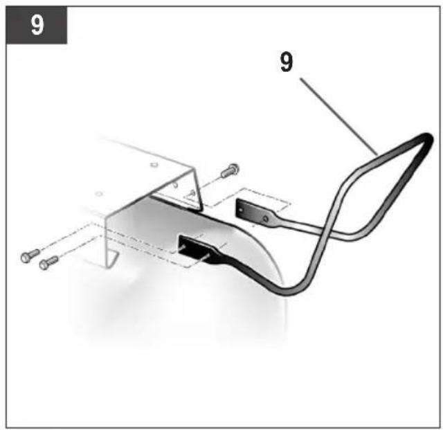
5.3 Fitting the transport handle (ref. 9)
Screw the transport handle (ref. 9) to the compressor as shown in Figures 9 and 10.
5.4 Voltage
5.4.1 Single-phase version
The compressor is equipped with a mains cable v shock-proof wire. Insert the plug of the electric cable in a socket of suitable shape, voltage and frequency complying with current regulations. Before you use the machine, make sure that the mains voltage complies with the specifications on the rating plate. Long supply cables, extensions, cable reels etc. cause a drop in voltage and impede motor start-up. In the case of low temperature below +5°C, motor start-up is jeopardized as a result of stiffness.
5.4.1.1 Connection of the mains plug (electrical information for the BS plug)
⚠️ Important!
The wires in the mains lead fitted to this product are coloured in accordance with the code shown in fig. 24.
• The 3 pin plug must comply to BS1363/A.
• Fuse must comply to BS1362.
If for any reason the 13 amp plug fitted to this product requires replacement it must be wired in accordance with the following instruction:
Do not connect the brown (live) or blue (neutral) to the earth pin marked 'E' on the 3 pin plug.
Connect the Blue wire to the terminal marked Neutral (N). Connect the Brown wire to the terminal marked Live (L). Connect the Yellow & Green wire to the terminal marked Earth (E). Ensure that the outer insulation is gripped by the cord grip and that the wires are not trapped when replacing the plug cover. The mains lead on this product is fitted with a 13 amp (BS1363/A) plug. A 13 amp (BS1362) fuse must be fitted in the plug.
If in doubt consult a qualified electrician
There are no user serviceable parts inside this product except those referred to in the manual. Always refer servicing to qualified service personnel. Never remove any part of the casing unless qualified to do so; this unit contains dangerous voltages.
Warning!
For your protection if this product is to be used outdoors it should not be exposed to rain or used in damp locations. Do not place the product on damp surfaces, use a workbench if available. For added protection use a suitable residual current device (R.C.D.) at the socket outlet.
Note: If the mains cable requires replacing it must be replaced with an identical one and fitted by a qualified person.
5.4.2 3-phase version
with Connect the mains cable to a panel protected by suitable fuses.
- For the versions fitted with electric panel ("Tandem" control units or delta/star starters) have installation and connections (to the motor, to the pressure switch and to the electrovalve if any) carried out by qualified person-canel.
Before you put the equipment into operation, check whether the motor rotates in the correct direction (see the direction arrow on the V-belt cover) by switching on the compressor briefly. If the compressor motor rotates in the wrong direction, you must correct the rotating field by reversing the phase converter in the plug (use a screwdriver to depress the phase converter slightly and turn it through 180°).
- The motor is equipped with an overload switch. If the compressor overloads, the overload switch will switch off the equipment automatically to protect the compressor from overheating. If the overload switch triggers, wait for the compressor to cool down.
- Long supply cables, extensions, cable reels etc. cause a drop in voltage and can impede motor start-up.
- In the case of low temperatures below +5°C, motor start-up is jeopardized as a result of stiffness.
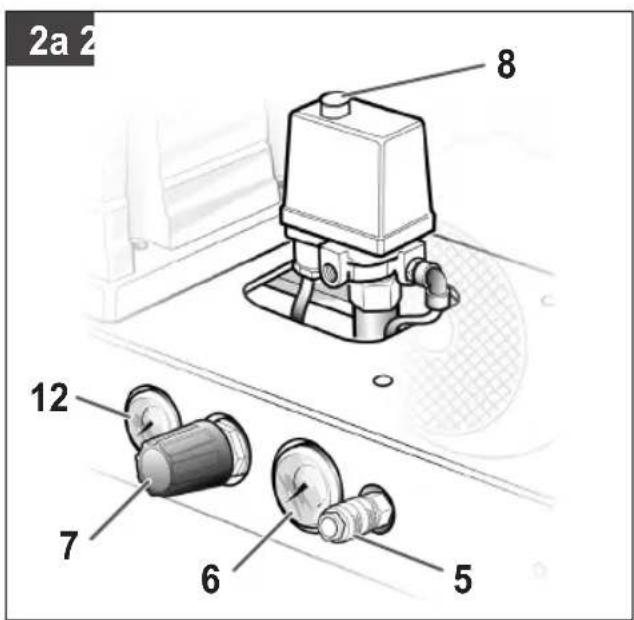
5.5 On/Off switch (ref. 8)
5.5.1 Single-phase version (Fig. 2a, 2c)
To switch on the compressor, pull out the red knob (ref. 8). To switch off the compressor, press the red knob (ref. 8) in again.
5.5.2 3-phase version (Fig. 2b)
To switch on the compressor, press the green knob (ref. 8.1).
To switch off the compressor, press the red knob (ref. 8.2) in again.
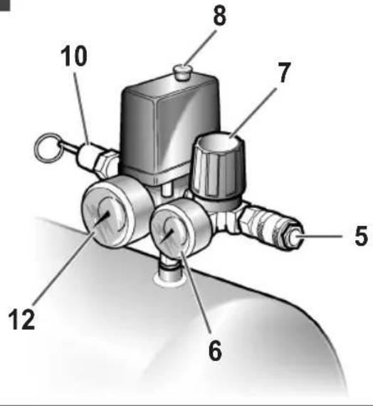
5.6 Adjusting the pressure (Figs.2a-2c)
- You can adjust the pressure on the pressure gauge (ref. 6) using the pressure regulator (ref. 7).
- The set pressure can be taken from the quicklock coupling (ref. 5).
5.7 Setting the pressure switch
The pressure switch is set at the factory.
Switch-on pressure: 8 bar
Switch-off pressure: 10 bar
6. CLEANING AND MAINTENANCE

Warning!
Pull the power plug before doing any cleaning and maintenance work on the appliance.

Warning!
Wait until the compressor has completely cooled down. Risk of burns!

Warning!
Always depressurize the tank before carrying out any cleaning and maintenance work.
6.1 Cleaning
- Keep the safety devices free of dirt and dust as far as possible. Wipe the equipment with a clean cloth or blow it with compressed air at low pressure.
- We recommend that you clean the appliance immediately after you use it.
- Clean the appliance regularly with a damp cloth and some soft soap. Do not use cleaning agents or solvents; these may be aggressive to the plastic parts in the appliance. Ensure that no water can get into the interior of the appliance.
- You must disconnect the hose and any spraying tools from the compressor before cleaning. Do not clean the compressor with water, solvents or the like.
6.2 Condensation water
The condensation water must be drained off each day by opening the drain valve (Fig. 3 - Ref. 11) (on the bottom of the pressure vessel).

Warning!
The condensation water from the pressure vessel will contain residual oil. Dispose of the condensation water in an environmentally compatible manner at the appropriate collection point.
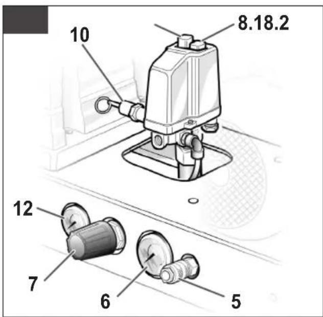
6.3 Safety valve (ref. 10)
The safety valve has been set for the highest permitted pressure of the pressure vessel. It is prohibited to adjust the safety valve or remove its seal.
6.4 Check the oil level at regular intervals
Place the compressor on a level and straight surface. The oil level must be between the two marks MAX and MIN on the oil level window (Fig. 12 / ref. 16).
Changing the oil: Recommended oil: SAE 15W/40 or an alternative of the same quality.
It should be refilled for the first time after 100 hours of operation. Thereafter the oil should be drained and refilled after every 300 hours in service.
6.5 Changing the oil
Switch off the engine and pull the mains plug out of the socket. After releasing any air pressure you can unscrew the oil drainage screw (ref. 15) from the compressor pump. To prevent the oil from running out in an uncontrolled manner, hold a small metal chute under the opening and collect the oil in a vessel. If the oil does not drain out completely, we recommend tilting the compressor slightly.
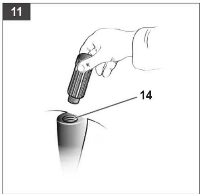
Dispose of the old oil at a drop-off point for old oil. When the oil has drained out, re-fit the oil drainage screw (ref. 15). Fill new oil through the oil filler opening (ref. 14) until it comes up to the required level. Then replace the oil sealing plug (ref. 14).
| MAINTENANCE RESUMPTIVE TABLE | |||
| FUNCTION | AFTER THE FIRST 100 HOURS | EVERY 100 HOURS | EVERY 300 HOURS |
| Cleaning of intake filter and/or substitution of filtering element | ● | ||
| Change of oil | ● | ● | |
| Tightening of head tension rods | The check must be carried out prior to the first compressor starting. | ||
| Draining tank condensate | Periodically and at the end of work. | ||
| Checking the tension of the belts | Periodically. | ||
6.6 Retensioning the V-belt (Figs.13-15)
- Pull out the power plug and remove the safety guard for the V-belt.
- Slacken the four motor fixing screws.
- Shift the motor until the V-belt is tensioned to the point where it can still be depressed by approx. 1-2 cm at the longest free position.
- Retighten the motor fixing screws and refit the safety guard for the V-belt.
6.7 Tightening of head tension rods
- Check that all screws (in particular those of the head of the unit) are tightly drawn up (fig. 16).
- The control must be performed before the first start-up of the compressor and subsequently before the first intensive use in order to restore the correct closing torque value modified as a result of heat expansion.
| TIGHTENING OF HEAD TENSION RODS | ||
| NmMin. torque | NmMax. torque | |
| Screw M6 9 11 | ||
| Screw M8 22 27 | ||
| Screw M10 45 55 | ||
| Screw M12 76 93 | ||
| Screw M14 121 148 | ||
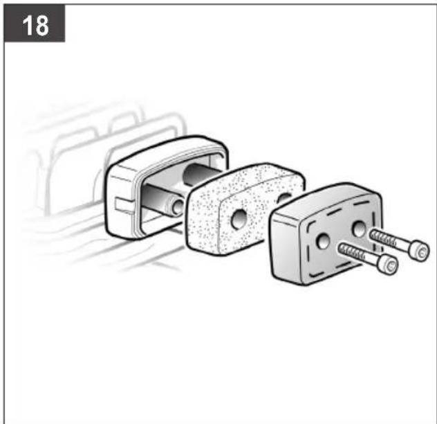
len screws. You can then remove the filter from the two halves of the plastic housing, tap it to remove the dirt, blast it down with low-pressure compressed air (approx. 3 bar) and re-insert it (Figures 17-18).
6.9 Storage
Warning!
Pull the mains plug out of the socket and ventilate the appliance and all connected pneumatic tools. Switch off the compressor and make sure that it is secured in such a way that it cannot be started up again by any unauthorized person.
Warning!
Store the compressor only in a dry location which is not accessible to unauthorized persons. Always store upright, never tilted!
7. DISPOSAL AND RECYCLING
The unit and its accessories are made of various types of material, such as metal and plastic. Defective components must be disposed of as special waste. Ask your dealer or your local council.
6.8 Cleaning the intake filter (ref. 1)
The intake filter prevents dust and dirt being drawn in. It is essential to clean this filter after at least every 100 hours in service. A clogged intake filter will decrease the compressor's performance dramatically. Undo the two Al-
8. POSSIBLE FAULTS AND RELATED PERMITTED REMEDIES
Request the assistance of a qualified electrician for operations on electric components (cables, motor, pressure switch, electric panel, etc).
| FAULT CAUSE | REMEDY | |
| Air leak from the valve of the pressure switch. | Check valve does not perform its function correctly due to wear or dirt on the seal. | Unscrew the hex-shaped head of the check valve, clean the housing and the special rubber disk (replace if worn). Re-assembler and tighten carefully (fig. 21-22). |
| Condensate drainage cock open. | Close the condensate drainage cock. | |
| Rilsan hose not inserted correctly in pressure switch. | Insert the Rilsan hose correctly inside the pressure switch. | |
| Reduction of efficiency, frequent start-up. Low pressure values. | Excessively high consumption. | Decrease the demand of compressed air. |
| Leaks from joints and/or pipes. | Change gaskets. | |
| Clogging of the suction filter. | Clean/replace the suction filter (fig. 17-18). | |
| Slipping of the belt. | Check belt tension (fig. 15). | |
| FAULT CAUSE REMEDY | ||
| The motor and/or the compressor overheat irregularly. | Insufficient ventilation. Improve | ambient conditions. |
| Closing of air ducts. Check and | if necessary clean the air filter. | |
| Insufficient lubrication. Top up or change oil. | ||
| After an attempt to start the compressor, it stops due to tripping of the thermal cutout caused by forcing of the motor. | Start-up with head of the compressor charged. | Release the compressor head by using the pressure switch push button. |
| Low temperature. Improve ambient conditions. | ||
| Voltage too low. | Check that the mains voltage matches that of the dataplate. Eliminate any extensions. | |
| Incorrect or insufficient lubrication. | Check level, top up and if necessary change the oil. | |
| Inefficient electrovalve. Call the Service Center. | ||
| During operation, the compressor stops for no apparent reason. | Tripping of the thermal cutout of the motor. | Check level oil. |
| Single-stage, mono-phase versions: operate on the button of the pressure switch returning this to the OFF position (par. 5.5.1). Reset the thermal cutout (fig. 19) and restart (par. 5.5.1). If the fault persists, call the Service Center. | ||
| Versions with delta-star starter: operate on the button of the thermal cutout located inside the box of the electric panel (fig. 20) and restart (fig. 2b). If the fault persists, call the Service Center. | ||
| Other versions: Operate on the button of the pressure switch returning this to the OFF position and then to ON again. If the fault persists, call the Service Center. | ||
| Electric fault. Call the Service Center. | ||
| When operating, the compressor vibrates and the motor emits an irregular buzzing sound. If it stops, it does not restart although the sound of the motor is present. | Single-phase motors: faulty capacitor. | Have the capacitor replaced. |
| 3-phase motors: One of the phases of the 3-phase power supply is missing due probably to blowing of a fuse. | Check the fuses inside the electric panel or the electric box and if necessary replace those that have been damaged (fig. 23). | |
| Irregular presence of oil in the network. | Too much oil inside the unit. Check oil level. | |
| Wear on segments. Call the Service Center. | ||
| Leaking of condensate from the vent cock. | Presence of dirt/grit inside the cock. | Clean the cock. |
Any other type of operation must be carried out by authorized Service Centers, requesting original parts. Tampering with the machine may impair its safety and in any case make the warranty null and void.
8. POSSIBLES ANOMALIES ET INTERVENTIONS ADMISES
5.5 Interruptor ON/OFF (8)
5.5.1 Versiones monofásicas (fig. 2a, 2c)
2. BESCHRIJVING VAN HET APPARAAT
5.5 AAN/UIT-schakelaar (ref. 8)
5.5.1 Monofase-versie (fig. 2a, 2c)
Indkoblingstryk 8 bar
Udkoblingstryk 10 bar
6. VEDLIGEHOLDELSE OG RENG∅RING
⚠️ Vigtigt!
5.5 Av/På-bryter (ref. 8)
6.3 Sikkerhetsventil (ref. 10)
VEDLIKEHOLDSINTERVALLER
⚠️ NI U KOJEM SLUČAJU
4. ÜLESSEADMISJUHISED
HOOLDUSE INTERVALVALLID
STANLEY, The STANLEY Logo, The Notched Rectangle and the
Yellow and Black Diagonal Package Design are all trademarks of
Stanley Black & Decker, Inc or an affiliate thereof and are used under license.
Product manufactured and distributed by:
FNA S.p.A. - Via Einaudi 6, Robassomero (TO) Italy.


- FR Légende
- Preserve this handbook for future reference
- PRECAUTIONS
- ▲ THINGS TO DO
- ▲ THINGS NOT TO DO
- ▲ THINGS YOU SHOULD KNOW
- LAYOUT
- SCOPE OF USE
- POINTS TO NOTE WHEN SETTING UP THE COMPRESSOR
- ASSEMBLY AND STARTING
- Fitting the wheels (Figs. 4-5)
- Fitting the supporting foot (only for B 25x/10/50, B 350/10/50, B480/10/50)
- Fitting the quick-lock coupling for tank pressure (ref. 13)
- Fitting the transport handle (ref. 9)
- Voltage
- Single-phase version
- Connection of the mains plug (electrical information for the BS plug)
- ⚠️ Important!
- Do not connect the brown (live) or blue (neutral) to the earth pin marked 'E' on the 3 pin plug.
- If in doubt consult a qualified electrician
- Warning!
- 3-phase version
- On/Off switch (ref. 8)
- Single-phase version (Fig. 2a, 2c)
- 3-phase version (Fig. 2b)
- Adjusting the pressure (Figs.2a-2c)
- Setting the pressure switch
- CLEANING AND MAINTENANCE
- Cleaning
- Condensation water
- Safety valve (ref. 10)
- Check the oil level at regular intervals
- Changing the oil
- Retensioning the V-belt (Figs.13-15)
- Tightening of head tension rods
- Storage
- DISPOSAL AND RECYCLING
- Cleaning the intake filter (ref. 1)
- POSSIBLE FAULTS AND RELATED PERMITTED REMEDIES
- POSSIBLES ANOMALIES ET INTERVENTIONS ADMISES
- Interruptor ON/OFF (8)
- Versiones monofásicas (fig. 2a, 2c)
- BESCHRIJVING VAN HET APPARAAT
- AAN/UIT-schakelaar (ref. 8)
- Monofase-versie (fig. 2a, 2c)
- VEDLIGEHOLDELSE OG RENG∅RING
- Av/På-bryter (ref. 8)
- Sikkerhetsventil (ref. 10)
- ⚠️ NI U KOJEM SLUČAJU
- ÜLESSEADMISJUHISED
Brand : STANLEY
Model : B3501050
Category : Compressor