WAD 101 - Welding machine Weller - Free user manual and instructions
Find the device manual for free WAD 101 Weller in PDF.
Frequently Asked Questions - WAD 101 Weller
Download the instructions for your Welding machine in PDF format for free! Find your manual WAD 101 - Weller and take your electronic device back in hand. On this page are published all the documents necessary for the use of your device. WAD 101 by Weller.
USER MANUAL WAD 101 Weller
5. Optical regulator
6. Equipotential bonding bush
7. Connection bush for soldering
8. Air Connection Nipple for
10. Power supply connector
for Compressed Air Connection
3. "UP" (Aug‰up) tausti¿‰
Please read these Operating Instructions and the attached Safety Information carefully prior to initial operation. Failure to observe the safety regulations results in a risk to life and limb. The manufacturer shall not be liable for damage resulting from misuse of the machine or unauthorised alterations. The Weller hot air station WAD 101 /WAD 101IG corresponds to the EC Declaration of Conformity in accordance with the basic safety requirements of Directives 2004/108/EC, 2006/95/EC and 2011/65/EC (RoHS).
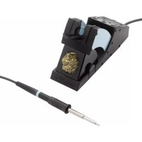
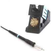
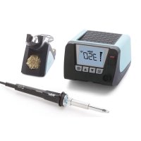
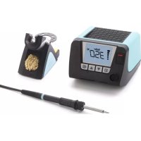
The WAD 101 is a hot air station that features a wide variety of functions. Control unit WAD 101IG The WAD 101IG is an inert gas soldering station designed for the operation of inert gas soldering irons WP 80IG and WP 120IG. As a result of the use of a microprocessor, the unit is straight- forward and easy to use. The control electronics ensure opti- mal adaptation of the control characteristics to different sol- dering tools. The soldering tools themselves are detected automatically and assigned the appropriate control parame- ters. Excellent dynamic behaviour is made possible by the particularly powerful 24 W heater elements. The soldering tool is thus of universal application. The required temperature can be set via 2 buttons (UP/DOWN). Temperatures from 50°C - 550°C (122°F - 999°F) are realisable with hot air soldering tools. When a soldering iron is connected, the adjustment range is automatically limited to max. 450°C (842°F). Required and actual values are displayed digitally. A flashing red LED indi- cates when the selected temperature is reached, this LED serves as an optical regulator monitor. The continuous illumi- nation of the LED indicates that the system is warming up. In the case of the control unit WAD 101, air flow is controlled by a finger switch integrated in the handle. The air flow is controlled via a finger operated switch integrated in the handle. The flow rate can be adjusted continuously over the range from approx. 0-10 l/min via a control valve. The hot air output is free of static charge. In the case of control unit WAD 101IG, gas flow is control- led by tool stand WDH 10T. The flow rate can be adjusted wit- hin the 0-5 l/min range. Various methods of equipotentially bonding the soldering iron bit, a zero voltage switch, and the anti-static design of the control unit and soldering tools supple ment the high stan- dard of the unit. The possibility of connecting an external input unit extends the functional diversity. Additional functi- ons including timing and interlocking can be realised using the WCB 1 and WCB 2 Input Units, available as optional extras. The extended featu- res of the WCB 2 Input Unit include an integrated temperatu- re measurement unit.
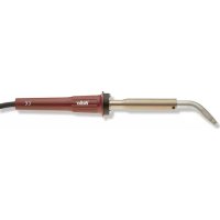
HAP 1: 100 W hot air soldering tool with integrated finger switch. Suitable for soldering and desoldering surface mounted com- ponents. A wide range of nozzles makes the tool of universal application. The hot air tool can cannot be operated with WAD 101IG WMP: The Weller Micro Soldering Iron WMP is suitable for processing SMD electronics due to its manageable design. The short distance between grip and soldering tip makes ergonomic handling of the 65 W soldering iron possible when carrying out very fine soldering tasks. MPR 80: The Weller Peritronic MPR 80 soldering iron has an adjusta- ble workingangle of 40° to enable an individually ergonomic soldering process. The 80-watt power and slim design makes this soldering iron suitable for fine soldering work. WTA 50: The unsoldering tweezers WTA 50 were specially designed for unsoldering SMD components. Two heating elements (2 x 25 watts), each with its own temperature sensor, ensure constant temperatures at both ends. LR 82: High-performance 80 watt soldering iron for soldering work with high heat requirements. The soldering tip is attached by a bayonet catch to ensure correct position when using different tips. English
WP 80 / WSP 80: The soldering iron WP 80 / WSP 80 is characterized by its capacity for reachingthe soldering temperature quickly and precisely. Its slim design and heating power of 80 watts makes universal usage possible - from extremely fine to high-temperature soldering work. Work can be continued immediately after switching soldering tips, since the tempe- rature is reached again quickly. See "Accessories" for additional tools.
Place the soldering tool in the holder. Insert compressed air hose with 6 mm outer diameter in the quick action coupling (12). Provide supply of compressed air with 400 kPa (58 psi) dry, oil-free compressed air or nitrogen (N2).
When using nitrogen, attention must be paid to satisfactory room ventilation. Plug the electrical lead from the soldering tool in the 7 pole socket (7) on the front panel and lock. Connect the compres- sed air hose to the compressed air connection nipple (8). Check that the mains voltage matches that on the rating plate and that the mains switch (1) is in the off position. If the mains voltage is correct, plug the control unit into the mains.
Do not direct hot air soldering tools at people or inflammable objects. Switch on the unit at the mains switch (1). When the unit is switched on, a self-test is performed during which all the indicators (2) are illuminated. The temperature set (required value) and the temperature scale (°C/°F) are then briefly dis- played. The electronics then switch automatically to the dis- play of the actual value. The red dot (5) on the display (2) illu- minates. This dot serves as an optical regulation monitor. Continuous illumination means that the system is heating up. Flashing indicates that the operating temperature has been reached. Setting the temperature The digital display (2) shows the actual value temperature. By pressing the UP or DOWN key (3, 4) the digital display (2) switches to the setpoint. The setpoint can be changed by tapping or by firmly pressing the UP or DOWN button (3, 4) in the desired direction. Pressing the button will change the setpoint quickly. The digital display (2) returns automatically to the actual value approximately 2 seconds after releasing the button. Adjusting the Air Flow Rate The air flow rate required can be adjusted at the flow control valve (9). Turning the control valve (9) to the left increases the flow rate. Air is fed to the hot air soldering tool as long as the finger operated switch is held down. Standard setback for control unit WAD 101: Setting back the set temperature to 150°C. The setback time, which follows the switching of the soldering station to standby mode, is 20 minutes. After three setback times (60 minutes) the ”AUTO-OFF” function is activated. The soldering tool is switched off (blinking line on the display). English Technical Data Dimensions in mm: 166 x 134 x 101 (L x B x H) Mains Voltage: 230 V / 50 Hz (120 V / 60 Hz) Power Consumption WAD 101: 105 W Power Consumption WAD 101IG: 150 W Protection Class: 1 (Control Unit) and 3 (Soldering Tool) Fuse: 230 V: T 630 mA (120 V: T 1,0 A) Temperature Regulation: °C Version Hot Air 50°C - 550°C Soldering Iron & inert gas soldering irons 50°C - 450°C °F Version Hot Air 122°F - 999°F Soldering Iron & inert gas soldering irons 122°F - 842°F Precision: Hot Air ± 30°C (± 54°F) Soldering Iron & inert gas soldering irons ± 9°C (± 17°F) Flow Rate: Approx. 0 - 10 l/min Control range of WAD 101IG: approx. 0 - 5 l/min. Compressed Air: Inlet pressure 400 kPa (58 psi), oil-free, dry compressed air or nitrogen (N2) Compressed Air Connection: Compressed air hose of 6 mm (0.24") diameter Inert gas pressure: The inlet pressure is set permanently to 200 kPa by a pressure regulator. The pressure regulator must not be adjusted.24 Setting: When switching on, hold the ”UP” key (3) until ON or OFF appears in the display. The setting is saved when the "UP" button is released. Repeat this step to change. Standard setback for control unit WAD 101IG After placing the soldering iron on its stand, the nominal tem- perature is reduced to 180°C and inert gas feed is shut off after 2 min. The "AUTO-OFF" function is deactivated.
4. Equipotential bonding
The various circuit elements of the 3.5 mm jack bush make 4 variations possible: Hard-grounded: No plug (delivery form) Equipotential bonding: With plug, equalizer at center contact (impedance 0 Ohms) Potential free: With plug Soft-grounded: With plug and soldered resistance. Grounding via set resistance value.
5. Instructions for use
Offset: The real temperature of the soldering iron can be changed by ± 40°C by input of a temperature offset.
Setback: Reduction of the required temperature set to 150°C / 300°F (standby). The set-back time, the time after which the soldering station switches into standby mode, can be adjusted from 0-99 minutes. The set-back condition is indicated by a flashing actual value display. After a period equal to three times the set-back time, „AUTO-OFF“ is activated. The soldering iron is switched off (flashing dash on the display). The set-back or auto-off condition is ended by pressing a button or finger switch pressure. During this process the required value set is briefly displayed.
Lock: Locking the setpoint temperature. Settings cannot be changed after the soldering station has been locked.
Window: Limitation of the temperature range to max. ± 99°C based on a locked temperature resulting from the "LOCK” function. The locked temperature represents the median point of the adjustable temperature range.
Cal: Re-adjustment of the soldering station (WCB 2 only).
PC interface: RS232 (WCB 2 only).
Temp. gauge: Integrated temperature gauge for thermal element Type K (WCB 2 only). Hot Air Soldering Tool The hot air nozzles are screwed into the heater element. To change the nozzle use the 8 SW socket spanner and lock the heater element with an open ended spanner. Important: The maximum thread depth is 5 mm (0.2"). A longer thread will irreparably damage the heater element. Nitrogen N2 reduces oxidation and flux remains active for longer. We recommend the nitrogen N2 that is available in steel bottles. The bottle must be equipped with a 0-10 bar pressure reducer. Soldering Iron The transition between the heater element/sensor and the soldering iron bit must not be degraded by dirt, foreign bodies or damage because these will have an effect on the precision of temperature regulation. When heating up for the first time, wet the selectively tinna- ble soldering iron bit with solder. This removes oxide layers and soiling that have formed during storage. Always ensure that the soldering iron bit is well tinned during breaks in sol- dering and when placing in the holder. Do not use aggressi- ve fluxes. Important: Always ensure that the soldering iron bit is correctly seated. English
The soldering equipment has been set up for a medium size bit or nozzle. Variations may occur if the bit is changed or if other bit shapes are used.
WP 120IG (PU WAD 101IG
2-side heated (Type D) D04 Hot air nozzle, 10,5 mm 10,5 mm T005 87 277 79 two sides heated, with hot plate D06 Hot air nozzle, 13,0 mm 10,0 mm T005 87 277 82 two sides heated, with hot plate D08 Hot air nozzle, 15,0 mm 10,0 mm T005 87 277 81 two sides heated, with hot plate D10 Hot air nozzle, 18,0 mm 10,0 mm T005 87 277 84 two sides heated, with hot plate 4 Side heated (Type Q) Q02 Hot air nozzle, 6,0 mm 6,5 mm T005 87 277 77 four sides heated, with hot plate Q04 Hot air nozzle 6,0 mm 9,0 mm T005 87 277 78 four sides heated, with hot plate Q06 Hot air nozzle 15,0 mm 10,0 mm T005 87 277 80 four sides heated, with hot plate Q08 Hot air nozzle 12,0 mm 15,0 mm T005 87 277 83 four sides heated, with hot plate Q10 Hot air nozzle 18,0 mm 18,0 mm T005 87 277 85 four sides heated, with hot plate SK709 Hot air nozzle, 12,0 mm 12,0 mm T005 87 278 12 four sides heated, with hot plate R01 Measuring nozzle for thermo element ø 0,5 mm T005 87 278 08 Hot Air Nozzles for HAP 1 Model Description Lenght X Widht Y Order-No.99
UK declaration of conformity We hereby declare that the products described herein comply with the following guidelines:
UK declaration of conformity We hereby declare that the products described herein comply with the following guidelines: