
TS 254 - Saw METABO - Free user manual and instructions
Find the device manual for free TS 254 METABO in PDF.
| Product type | Table saw |
| Brand | Metabo |
| Model | TS 254 |
| Supply voltage | 220-240 V / 50-60 Hz |
| Power input | 2.00 kW (S6 20%) |
| Output power | 1.27 kW (S6 20%) |
| Rated current | 9 A |
| Fuse protection | 16 A (slow-blow) |
| No-load speed | 4,200 rpm |
| Cutting speed | 57 m/s |
| Blade diameter | 250-254 mm |
| Blade bore | 30 mm |
| Max. cutting height (vertical) | 87 mm |
| Max. cutting height (45°) | 50 mm |
| Max. cutting width (parallel) | 630 mm |
| Max. cutting width (cross-cut) | 200 mm |
| Dimensions (with stand) | 790 x 945 x 850 mm |
| Weight (with stand) | 33.4 kg |
| Sound pressure level | 99 dB(A) |
| Sound power level | 112 dB(A) |
| Protection degree | IP 20 |
| Blade tilt adjustment | -1.5° to 46.5° |
| Safety devices | Riving knife, protective guard, push stick |
| Chip extraction | Guard connection 38 mm, housing connection 35/44 mm |
| Operating instructions | Downloadable PDF manual |
Frequently Asked Questions - TS 254 METABO
User questions about TS 254 METABO
0 question about this device. Answer the ones you know or ask your own.
Ask a new question about this device
Download the instructions for your Saw in PDF format for free! Find your manual TS 254 - METABO and take your electronic device back in hand. On this page are published all the documents necessary for the use of your device. TS 254 by METABO.
USER MANUAL TS 254 METABO
We herewith declare in our sole responsibility that this product complies with the following standards in accordance with the regulations of the undermentioned Directives EC type examination *** conducted by ***
NL
DEKRA Testing and Certification GmbH, Enderstraße 92b, 01277 Dresden, Germany, Notified Body No. 2140

Volker Siegle
Director Innovation, Research and Development
Dokumentationsbevollmächtigter/Responsible person for documentation/Chargé de la documentation
Metabowerke GmbH
Metabo-Allee 1
D-72622Nurtingen

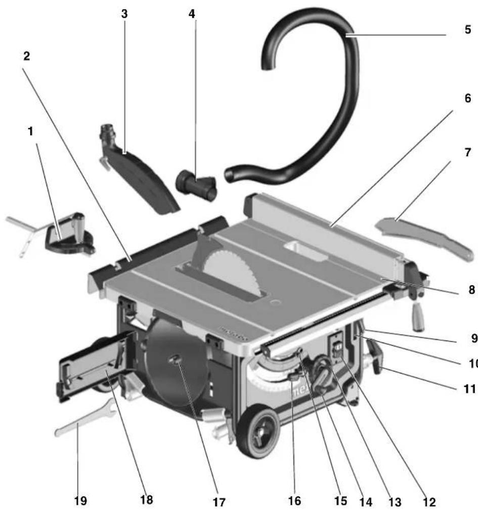
1 Mitre fence
2 Table extension
3 Blade guard
4 Extraction adapter
5 Extraction hose
6 Rip fence
7 Push stick
8 Table side extension
9 Lock lever for table side extension
10 Push stick holder
11 Foot/handle
12 On/off switch
13 Handwheel for adjusting bevel angle
14 Crank for adjusting cutting depth
15 Bevel limitation stop
16 Ratchet lock lever to lock saw blade tilt
17 Saw blade holder
18 Toolholder
19 Open end wrench
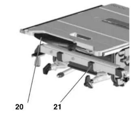
20 Blade guard holder
21 Rip fence holder
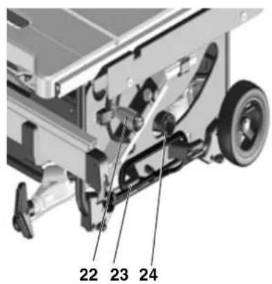
22 Mitre fence holder
23 Cable holder
24 Chip ejection
Contents
- Getting To Know Your Saw
- Read first!
- Safety
- Installation
- Commissioning
- Operation
- Transport
- Care and Maintenance
- Tips and Tricks
- Available Accessories
- Repairs
- Disposal
- Troubleshooting
- Technical Specifications
2. Please Read First!

WARNING - Reading the operating instructions will reduce the risk of injury.
WARNING - Read all safety warnings and instructions. Failure to follow all safety warnings and instructions may result in electric shock, fire and/or serious injury.
Keep all safety instructions and information for future reference. Pass on your power tool only together with these documents.
-
These instructions are intended for persons having a basic technical knowledge of the operation of machines such as the one described herein. If you have no experience whatsoever, we strongly recommend to seek the advise of an experienced person.
-
The equipment manufacturer is not liable for any damage resulting from neglect of these operating instructions.
Information in these operating instructions is categorised as shown below:

Danger!
Risk of personal injury or environmental damage.
Risk of electric shock! Risk of personal injury by electric shock.
Drawing-in/trapping hazard!
Risk of personal injury by body parts or clothing being drawn into the rotating saw blade.

Caution!
Warning against property damage.

Note:
Additional information.

3. Safety
3.1 Specified Use
This machine is intended for ripping and crosscutting grown timber, faced boards, chip board and wood-core ply
wood sheets, and similar wood-derived materials.
Metals can only be cut with the following restrictions:
- With suitable saw blade only (see "Available Accessories")
Non-ferrous metals only (no hard or hardened metals)
Do not cut round stock without suitable jigs or fixtures. The rotating saw blade could turn the workpiece.
When sawing thin stock laid on its edge, a suitable guide must be used for firm support.
The tool must not be used for grooving and slot cutting without a suitable guard.
Do not use circular saws for slitting (groove ended in workpiece)
Any other use is considered to be not as specified and not allowed. The manufacturer is not liable for any damage caused by unspecified use.
Modification of the machine or use of parts not approved by the equipment manufacturer can cause unforeseeable damage!
3.2 General safety instructions
Caution! When using power tools, the following basic safety measures must be taken to protect against electric shock, other injury or fire.
- When using this tool observe the following safety instructions, to exclude the risk of personal injury or material damage.
- Please also observe the special safety instructions in the respective chapters.
- Where applicable, follow the legal directives or regulations for the prevention of accidents pertaining to the use of circular saws.

General hazards!
- Keep your work area tidy - a messy work area invites accidents.
- Be alert. Know what you are doing. Set out to work with reason. Do not operate tool while under the influence of drugs, alcohol or medication.
-
Consider environmental conditions: keep work area well lighted.
-
Prevent adverse body positions. Ensure firm footing and keep your balance at all times.
- Use suitable workpiece supports when cutting long stock.
- Never use power tools in areas where there is a risk of fire or explosion.
- The saw shall only be started and operated by persons familiar with circular saws and who are at any time aware of the dangers associated with the operation of such tool. Persons under 18 years of age shall use this tool only in the course of their vocational training, under the supervision of an instructor.
- Keep bystanders, particularly children, out of the danger zone. Do not permit other persons to touch the tool or power cable while it is running.
- Do not overload tool - use it only within the performance range it was designed for (see "Technical Specifications").

Danger! Risk of electric shock!
- Do not expose tool to rain.
- Do not operate tool in damp or wet environment.
- Prevent body contact with earthed objects such as radiators, pipes, cooking stoves, refrigerators when operating this tool.
- Do not use the power cable for purposes it is not intended for.

Risk of personal injury and ing by moving parts!
- Do not operate the tool without installed guards.
Always keep sufficient distance to the saw blade. Use suitable feeding aids, if necessary. Keep sufficient distance to driven components when operating the power tool. - Wait for the saw blade to come to a complete stop before removing cutoffs, scrap, etc. from the work area.
- Do not attempt to stop the saw blade by pushing the workpiece against its side.
- Ensure the tool is disconnected from power before servicing.
-
Ensure that when switching on (e.g. after servicing) no tools or loose parts are left on or in the tool.
-
Turn power off if the tool is not used.
Cutting hazard, even with the cutting tool at standstill!
- Wear gloves when changing cutting tools.
- Store saw blade in such manner that nobody will get hurt.
Risk of kickback (workpiece is caught by the saw blade and thrown against the operator):
Always work with a properly set riv- ing knife.
- The riving knife and the saw blade used must match: the riving knife should be thinner than the kerf, but thicker than the saw blade body.
- Do not jam workpieces.
- Make sure the saw blade is suitable for the workpiece material.
- Cut thin or thin-walled workpieces only with fine-toothed saw blades.
Always use sharp saw blades. - If in doubt, check workpiece for inclusion of foreign matter (e.g. nails or screws).
- Cut only stock of dimensions that allow for safe and secure holding while cutting.
- Never cut several workpieces at the same time – and also no bundles containing several individual pieces. Risk of personal injury if individual pieces are caught by the saw blade uncontrolled.
- Remove small cutoffs, scrap, etc. from the work area – when doing so the saw blade must be at a complete standstill.

Drawing-in/trapping hazard!
- Ensure that no parts of the body or clothing can be caught and drawn in by rotating components (no neckties, no gloves, no loose-fitting clothes; contain long hair with hair-net).
-
Never attempt to cut any workpieces which contain
-
ropes ,
- s t r i n g s ,
- c o r d s ,
-cables or
-wires, or to which any of the above are attached.
Hazard generated by insufficient personal protection gear!
- Wear hearing protection.
- Wear protective goggles.
- Wear dust mask.
- Wear suitable work clothes.
- When working outdoors wearing of non-slip shoes is recommended.
- Wear gloves when handling saw blades and rough workpieces. Carry saw blades in a container.
Risk of injury by inhaled wood dust!
- Dust of certain timber species (e.g. beech, oak, ash) can cause cancer when inhaled. Work only with a suitable dust collector attached to the saw. The dust collector must comply with the data stated in the technical specifications.
-
Ensure that as little as possible wood dust will get into the environment:
-
remove wood dust deposit in the work area (do not blow away!);
fix any leakages on the dust collector; -
ensure good ventilation.
Hazard generated by modification of the machine or use of parts not tested and approved by the equipment manufacturer!
- Assemble tool in strict accordance with these instructions.
- Use only parts approved by the equipment manufacturer. This applies especially for:
-saw blades (for order numbers, refer to Available Accessories);
- safety devices (for order numbers, see spare parts list spare parts list).
- Do not change any parts.
Hazard generated by tool defects!
-
Keep tool and accessories in good repair. Observe the maintenance instructions.
-
Before every use check tool for possible damage: before operating the tool all safety devices, protective guards or slightly damaged parts need to be checked for proper function as specified. Check to see that all moving parts work properly and do not jam. All parts must be correctly installed and meet all conditions necessary for the proper operation of the tool.
- Damaged protection devices or parts must be repaired or replaced by a qualified specialist. Have damaged switches replaced by a service centre. Do not operate tool if the switch cannot be turned ON or OFF.
- Keep handles free of oil and grease.
Risk of injury by noise!
- Wear hearing protection.
- Make sure the riving knife is not bent. A bent riving knife will push the workpiece against the side of the saw blade, causing noise.
Danger from blocking workpieces or workpiece parts!
If blockage occurs:
- switch machine off,
- unplug mains cable,
3.wear gloves, - clear the blockage using a suitable tool.
3.3 Symbols on the machine
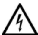
Information on the nameplate:
(25) Manufacturer
(26) Serial number
(27) Machine designation
(28) Motor specifications (see also "Technical specifications")
(29) CE-mark - This machine conforms to the EC directives as per Declaration of Conformity
(30) Waste disposal symbol - the machine can be disposed of through the manufacturer
(31) Year of manufacture
(32) Dimensions of permissible saw blades
Safety symbol

Danger! Failure to observe the following warnings can result in serious injury or damage to property.

Read the operating instructions.
Never place hands into running saw blade.
Wear protective goggles and ear protectors.
Never operate the tool in a damp or wet environment.
3.4 Safety devices
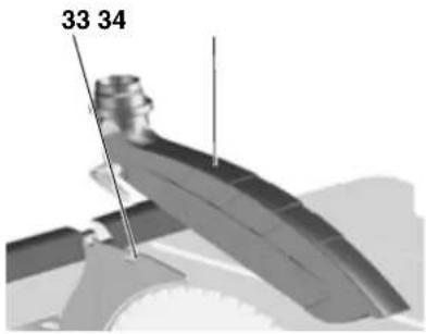
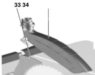
Riving knife
The riving knife (33) prevents the workpiece from being caught by the rising teeth of the saw blade and being thrown against the operator.
Always have the riving knife installed during operation.
Blade guard
The blade guard (34) protects against unintentional contact with the saw blade and from chips flying about.
Always have blade guard installed during operation.
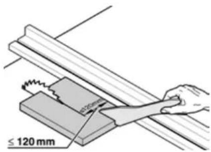
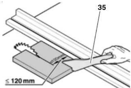
Push stick
The push stick (35) serves as an extension of the hand and protects against accidental contact with the saw blade.
Always use push stick if distance between saw blade and rip fence is less than 120mm
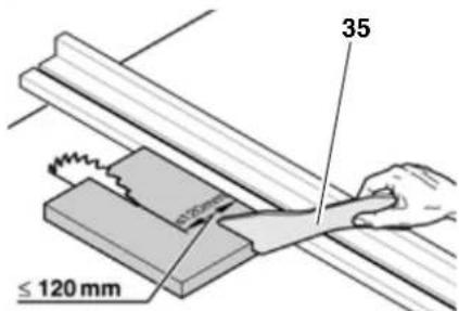
Guide the push stick at an angle of 20^ ... 30^ against the saw table's surface.
If the push stick is not used, it has to be stored with the machine.
Replace push stick if damaged.
4. Installation

Ensure firm footing and keep balance at all times.
Installation without machine stand:
- Lift saw with two persons out of packaging.
- Place saw down on stable table or work bench.
- Bolt saw firmly onto table or work bench.
Installation with machine stand:
- Lift tool with two persons out of packaging.
- Place tool on ground.
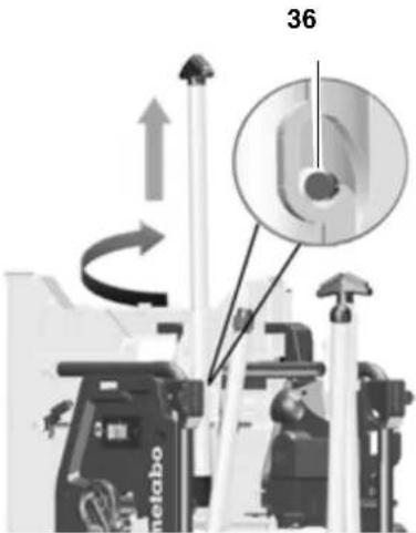
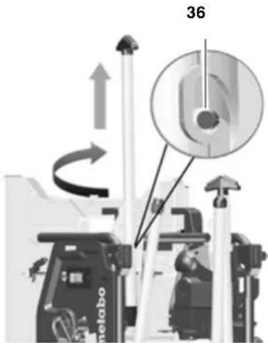
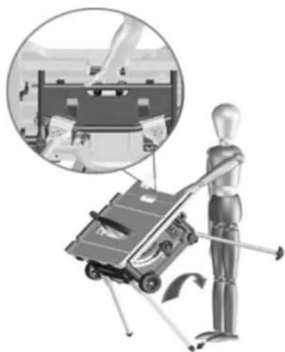
- Lift tool by handles and set up on edge
- Pull out handles (36), turn them and engage them.
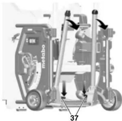
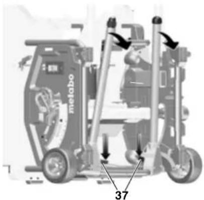
- Fold out the two table legs. To do this, press the red turning lever (37) downwards (with your foot or hand) and swing down the table legs.
- Tilt the tool slightly to the rear and press down both table legs. The red turning levers (37) must engage.
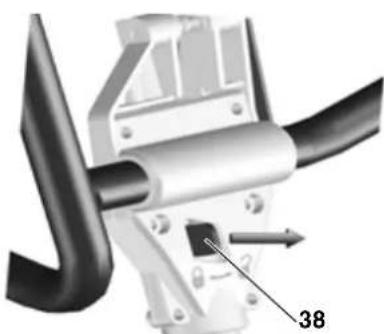
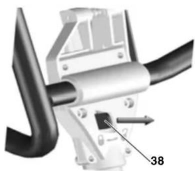
- Fold out the upper two table legs. To do this, push the red turning lever (38) to the right and swing the table legs downwards. The red turning levers must engage.
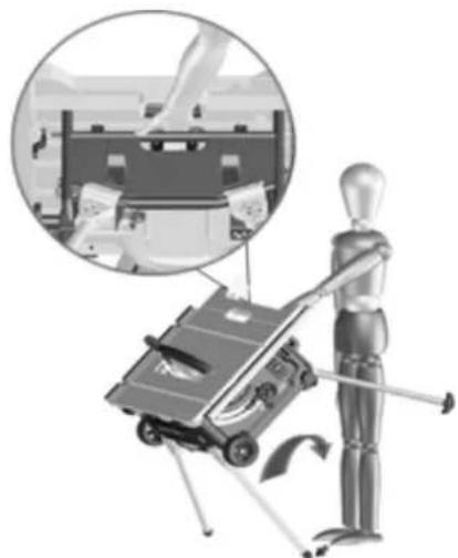
- Hold the saw round the centre of the upper frame. Pull up saw and set down. (Hold adjustable base in position with foot to prevent slipping of the saw during installation).
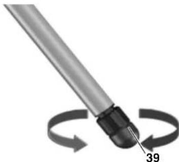
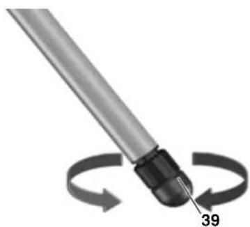
9. Compensate for floor irregularities with the adjustable base (39).
5. Initial Operation
5.1 Assembly
Riving knife

Note:
The riving knife has been correctly set at the factory. Readjustment prior to initial operation is only required should the riving knife have become misadjusted in transit.
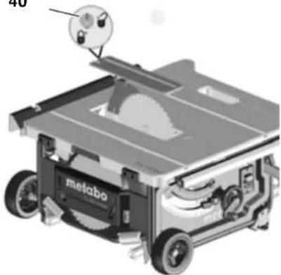
- Raise saw blade fully.
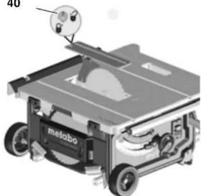
- Turn screw (40) counterclockwise, raise table insert and remove.
40
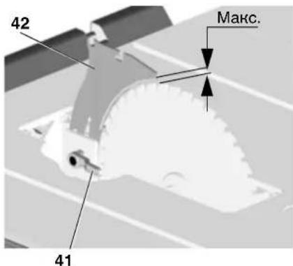
- Release locking lever (41) (turn counterclockwise!).
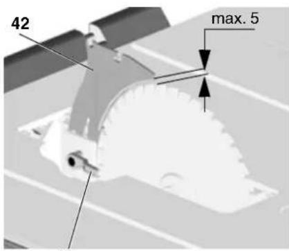
- Pull riving knife (42) out of lower transport position upwards as far as the stop.
41
-
Checking the riving knife:
-
Distance between the saw blade's outer edge and the riving knife needs to be 3 to 5 mm.
- The riving knife must be in alignment with the saw blade.

Danger!
The riving knife is one of the safety devices and must be correctly installed for safe operation.
Only if realignment of the riving knife is necessary:
- Release locking lever (41) (turn counterclockwise!).
- Align riving knife (42) vertically: Distance between the saw blade's outer edge and the riving knife needs to be 3 - 5mm .
- Tighten locking lever (41) (turn clockwise!).
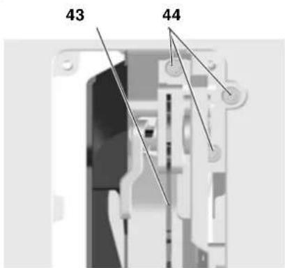
Lateral alignment: riving knife and saw blade (43) must be in true alignment.
4. Release three Allen screws (44).
5. Align riving knife (43) flush with saw blade.
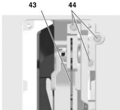
6. Tighten three Allen screws (44).
- Secure table insert and lock with screw (40).
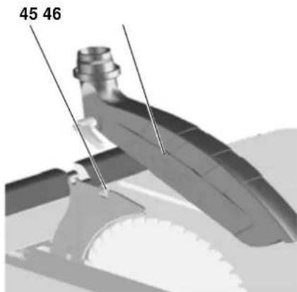
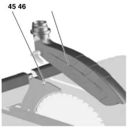
Blade guard installation
- Raise saw blade fully.
- Install blade guard (46) on front mounting on riving knife (45).
- Firmly tighten blade guard with lock lever.
5.2 Mains connection

Danger! High voltage
- Operate this machine in dry surroundings only.
- Operate machine only on a power source meeting the following requirements (see also "Technical Specifications"):
outlets properly installed, earthed, and tested.
- mains voltage and system frequency conform to the voltage and frequency shown on the machine's rating label;
- fuse protection by a residual current operated device (RCD) of 30mA sensitivity;
i Note:
Check with your local Electricity Board or electrician if in doubt whether your house service connection meets these requirements.
- Position power supply cable so it does not interfere with the work and is not damaged.
- Protect power supply cable from heat, aggressive liquids and sharp edges.
- Use only rubber-jacketed extension cables with sufficient lead cross-section (see "Technical Specifications").
- When working out of doors, only use extension cables that are also approved for outdoors.
- Do not pull on power supply cable to unplug.
- Avoid accidental start-up: ensure that the on/off switch is switched off when inserting the plug in the socket.
6. Operation

Risk of injury!
This saw may only be operated by one person at a time. Other persons shall stay only at a distance to the saw for the purpose of feeding or removing stock.
Before starting work, check to see that the following are in proper working order:
-power cable and plug
-ON/OFF switch
- riving knife
blade guard
- feeding aids (push stick, push block and handle).
Use personal protection gear:
- dust respirator
-hearing protection; - safety goggles
Assume proper operating position:
- at the front of the saw;
-in front of the saw; - to the left of the line of cut;
- when working with two persons, the other person must remain at an adequate distance to the saw.
If the type of work requires, use the following:
- suitable workpiece supports - if otherwise workpiece would fall off the table after cutting;
-dust collector.
Avoid typical operator mistakes:
- Do not attempt to stop the saw blade by pushing the workpiece against its side. Risk of kickback.
Always hold the workpiece down on the table and do not jam it. Risk of kickback. - Never cut several workpieces at the same time - and also no bundles containing several individual pieces. Risk of personal injury if individual pieces are caught by the saw blade uncontrolled.

Drawing-in/trapping hazard!
Never cut stock to which ropes, cords, strings, cables or wires are attached or which contain such materials.
6.1 Dust collector / universal vacuum cleaner

Danger!
Dust of certain timber species (e.g. beech, oak, ash) can cause cancer when inhaled. Use suitable dust collector when working in enclosed spaces. The dust collector must meet the following requirements:
- fits the diameter of the dust extraction ports (blade guard 38mm ; chip case 35/44mm );
air flow volume ≥ 460m^3 /h
vacuum at dust extraction port of saw ≥ 530 Pa;
-air speed at dust extraction port of saw ≥ 20m / s
The dust extraction ports are located at the chip case assembly and at the saw blade guard.
Observe the dust collector's operating instructions as well!
Operation without a dust collector is only possible out of doors.
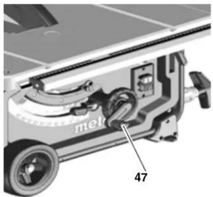
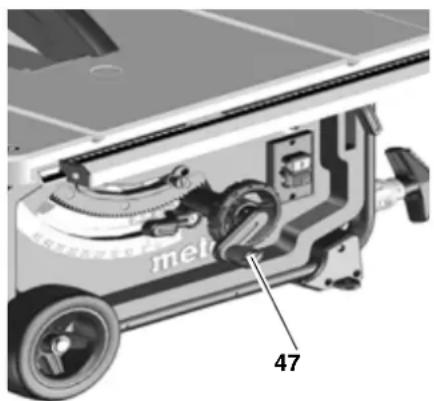
6.2 Setting the depth of cut
Danger!
Parts of the body or objects in the setting range can be caught by the
running saw blade! Set depth of cut only with saw blade at standstill!
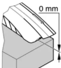
The saw blade's cutting depth needs to be adapted to the workpiece height: the blade guard shall rest with its front edge on the workpiece.

- Adjust depth of cut by turning the handwheel (47) as required.

Note:
To compensate for possible play in the blade height setting mechanism, always raise the blade to the desired position.
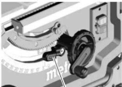
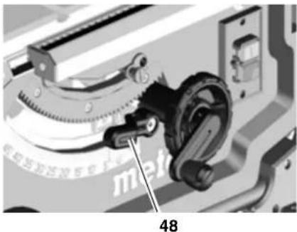
6.3 Setting the saw blade tilt

Danger!
Parts of the body or objects in the setting range can be caught by the running saw blade! Set the depth of cut only with the saw blade at stand-still!!
The blade bevel angle can be adjusted between -1.5^ and 46.5^ .
- Release lock lever (48).
- Set required saw blade tilt.
48
- Lock the set bevel tilt by tightening the lock lever (48).
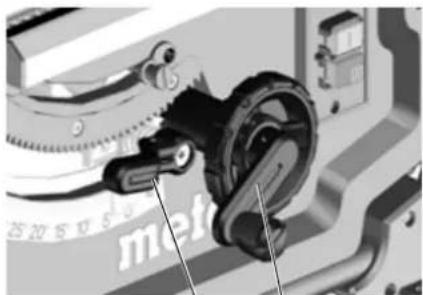
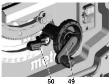
Handwheel for cutting depth adjustment
The depth of cut can be adjusted by turning the handwheel (49).
Lock lever for bevel angle adjustment
By releasing the lock lever (50), the saw blade can be adjusted between -1.5^ and 46.5^ .
50
To keep the set bevel angle from changing during cutting, it must be locked again by the lock lever (50).
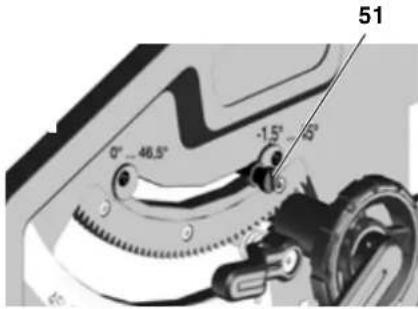
Release lever for bevel tilt stop
The blade tilt setting has end stops at 0^ and 45^ . For special bevel cuts (undercutting) the bevel angle can be increased by 1.5^ in both directions.
- Withdraw bevel angle limitation stop (51) and place over the right-hand cam plate = bevel angle of saw blade adjustable between -1.5° and 45°.
- Withdraw bevel angle limitation stop (51) and place over the left-hand cam plate = bevel angle of saw blade adjustable between 0^ and 46.5^ .
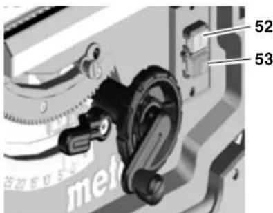
On/off switch
To stop = press upper switch (52).
To start = press and hold lower switch (53) for 1-2 seconds.
6.4 Adjusting rip fence
For use as rip fence the long fence extrusion (54) must be installed. It is mounted on the guide extrusion at the front of the saw table.
- Position rip fence to the right of the saw blade. The marking in the magnifying glass shows the set distance between the rip fence and the saw blade on the scale.
- Release lock lever (55) of rip fence and shift rip fence until marking in magnifying glass indicates the desired distance to the saw blade.
Press lock lever (55) downwards to lock.
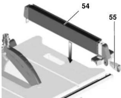
-For ripping, the fence extrusion (54) must be parallel with the saw blade and locked in position by the lock le
ver (55). Press lock lever downwards to do this.
- Knurled nuts (56) for attaching the fence extrusion. After loosening the two knurled nuts (56), the fence extrusion can be removed and shifted:
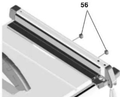
Small edge:
- for cutting thin stock;
- when the saw blade is tilted.
Wide edge:
- for cutting thick stock (max. 87 mm).
6.5 Adjusting pointer on rip fence
- Align rip fence with saw blade.
- Loosen rip fence pointer fixing screw.
- Bring pointer on rip fence and "O" on scale into alignment.
- Retighten rip fence pointer fixing screw.

Note:
To avoid stock jamming when cutting along the rip fence: slide rip fence all the way to the right table edge and then back to the required cutting width.

Note:
Adjust parallel stop (if necessary): To prevent the workpiece from jamming between parallel stop and saw blade, the parallel stop must be aligned to the saw blade, or set to a max. of 0.3mm opening to the rear. To adjust it, release the 2 screws on the upper side of the parallel stop and then tighten again.

Note:
Adjust clamping force of the parallel guide (if required): If the rear clamp rear clamping piece clamps earlier or later to the front clamping piece, this can be adjusted by turning the nuts (on the rear). Loosen the nut so that the rear clamping
piece clamps later. Tighten the nut so that th
6.6 Setting metre fence
The metre fence (58) is inserted into the table slot from the table's front edge.
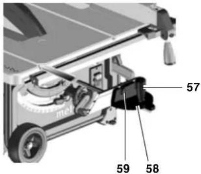
For litre cuts the litre fence turns to 60^ in both directions.
For 45^ and 90^ litres positive stops are provided.
To set a litre angle: loosen locking handle (57) by turning it counter-clockwise.

Risk of injury!
When cutting with the metre fence the handle must be firmly tightened.
The auxiliary fence extrusion can be taken off and reversed after loosening knurled nut (59).
6.7 Adjusting table side extension
The table side extension extends the supporting surface, providing safe support for larger workpieces.
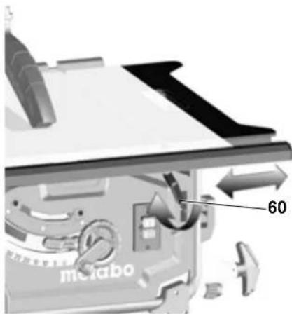
- For table side extension adjustment, the lock lever (60) must be released.

Risk of injury!
When cutting, the handle must always be firmly tightened.
Scale reading when using the rip fence
On which scale the cutting width is read depends on how the fence extrusion is installed on the rip fence:
- Wide edge = scale with black numerals on white background.
- Small edge = scale with white numerals on black background.
For small cutting widths the table side extension is not extended. The cuttings width is read on the respective right-hand scale at the rip fence's pointer:
- Wide edge: cutting width from 0 to 35 cm.
- Small edge: cutting width from 0 to 29.5 cm.
If larger stock is to be cut, the table side extension needs to be extended.
- Shift rip fence to the end position on the scale.
- Pull out table side extension and set rip fence to desired cutting width. The cuttings width is read on the respective left-hand scale at the scale's pointer.
6.8 Adjusting table extension
The table extension extends the supporting surface, providing safe support for larger workpieces.
- To pull out the table extension, both knurled screws (61) must be released.
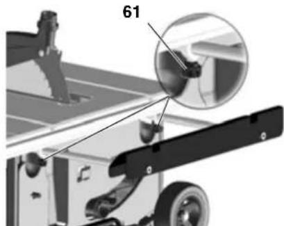
- Withdraw table extension and set to desired distance.
- Retighten both knurled screws.
6.9 Sawing

Danger!
Always use push stick if distance between saw blade and rip fence is less than 120~mm
Straight cut
- Set blade tilt and lock in position.
- Set depth of cut. The blade guard must rest with its front edge on the workpiece.
- Adjust rip fence.
- Start saw.
- Push workpiece in a steady motion towards the rear and cut in a single pass.
- Switch machine off if no further cutting is to be done immediately afterwards.
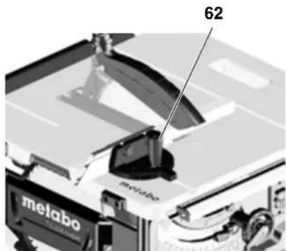
Mitre cuts
- The metre fence is inserted into the table slot from the table's front edge.
- Set desired angle after loosening the mitre fence's locking handle (62) and retighten locking handle.
-
Adjust lateral distance between auxiliary fence and saw blade:
-
Release knurled nut and move auxiliary fence as required.
- Tighten knurled nut.
-
Hold workpiece firmly against mitre fence.
-
Cut workpiece by pushing the mitre fence forward.
- Switch machine off if no further cutting is to be done immediately afterwards.
7. Transport

Danger!
Before every transport:
- switch machine off.
- wait for saw blade to come to standstill.
- unplug mains cable.
- Lower saw blade fully.
- Set saw blade bevel angle to 0^ and lock with lock lever.
- Remove add-on parts (blade guard, dust extraction). Store blade guard at saw table.
Wind up mains cable on cable reel.
Only tools with machine stand:
- Raise tool on frame and swing to the rear. Set up machine on its edge and fold in upper legs. The red turning levers must engage again.
- Swing machine to the rear and fold in the lower legs. The red turning levers must engage again.
- Push in handles and set down machine.

Crushing hazard
Lock pulled-out table side extension with lock lever.
Use handles (63) provided on sides of table to carry the machine.
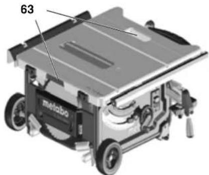

Caution!
Do not carry the machine at the
guards, table side extension or operating elements!
Mobile transport:
Pull out handle, turn it and engage it.
Pull or push saw with handle

If possible use original carton for shipping.
8. Care And Maintenance

Danger!
Prior to all servicing:
-
switch machine off.
-
wait until the saw has come to a complete stop.
-
unplug mains cable.
-
Check that all safety devices are operational again after each service.
-Replace defective parts, especially safety devices, only with genuine replacement parts. Parts not tested and approved by the equipment manufacturer can cause unforeseen damage. - Repair and maintenance work other than described in this section should only be carried out by qualified spec. cialists.

Danger!
With a damaged table insert there is a risk of small parts getting stuck between table insert and saw blade, blocking the saw blade. Replace damaged table inserts immediately!
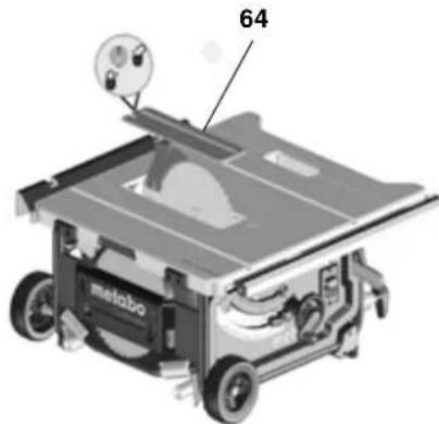
8.1 Saw blade change

Danger!
Directly after cutting the saw blade can be very hot - burning hazard!
Let a hot saw blade cool down. Do not clean the saw blade with combustible liquids.
Risk of injury, even with the blade at standstill. Wear gloves when changing blades.
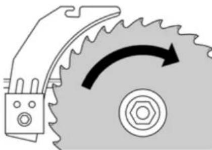
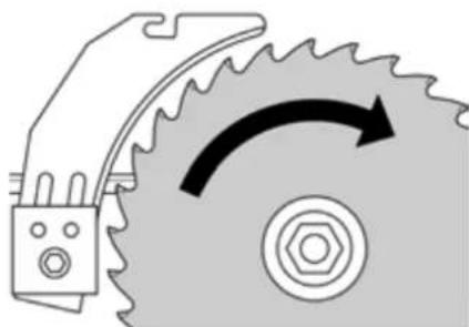
When fitting a saw blade, observe the direction of rotation!
- Raise saw blade fully.
- Remove blade guard.
- Loosen table insert (64) and remove from table.

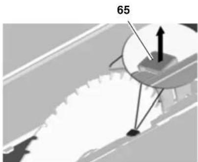
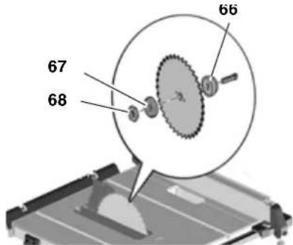
- Turn clamping nut (68) with open-jawed spanner and, at the same time, pull lever for saw blade lock (65) upwards until it engages.

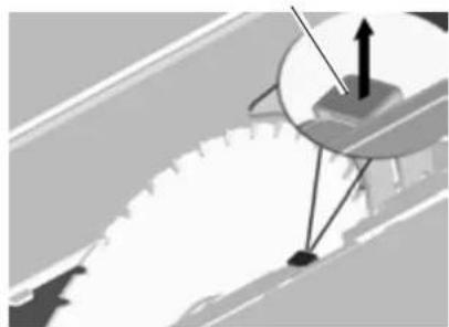
- Hold lever firmly in position and unscrew clamping nut clockwise.
- Remove clamping nut (68), outer blade flange (67) and saw blade from saw spindle.
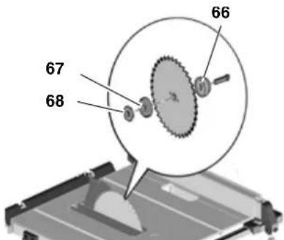
- Clean clamping surfaces of saw blade flange (66) and (67) and saw blade.
Danger!
Do not use cleaning agents (e.g. to remove resin residue) that could corrode the light metal components of the saw; the stability of the saw would be adversely affected.
- Push inner saw blade flange (66) onto motor shaft.
- Put on a new saw blade (observe direction of rotation!).
Danger!
Use only saw blades conforming to the technical specifications stated and to EN 847-1 - if unsuitable, damaged or deformed saw blades parts are used, parts can be ejected due to centrifugal force in an explosive-type manner.
Do not use:
-saw blades which permissible maximum speed is below the rated no-load speed of the saw spindle (see "Technical Specifications");
-saw blades made of high speed steel (HS or HSS);
-saw blades whose cutting width is less than, or whose blade body is thicker than, the thickness of the riving knife.
-saw blades with visible damage;
-cut-off wheel blades.
Danger!
- Mount saw blade using only genuine parts.
- Do not use loose-fitting reducing rings; the saw blade could work loose.
Saw blades have to be mounted in such way that they do not wobble or run out of balance and cannot work loose during operation. -
Slide on outer blade flange (67).
-
Screw on clamping nut (68) (left-handed thread!). Turn clamping nut (68) with open-jawed spanner and, at the same time, pull the lever of the saw blade lock (65) upwards until is engages.
- Hold lever firmly in position and tighten clamping nut hand-tight by turning counterclockwise.
#
Danger!
- Do not extend arbor bolt tightening wrench.
- Do not tighten arbor bolt by hitting the wrench.
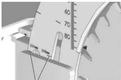
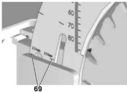
- Adjust riving knife corresponding to the saw blade size (69). (for riving knife setting, see 5.1)
69
- Reinstall table insert.
- Attach blade guard.
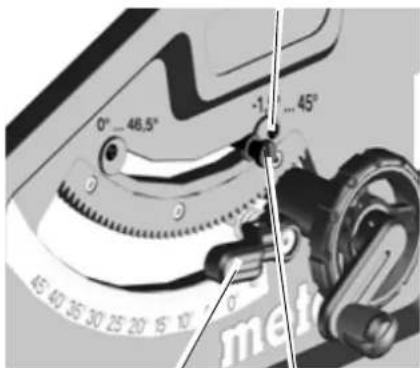
8.2 Adjusting the blade tilt stop
- Set the blade tilt stop lever (71) for the angle range to 0^ / 45^ .
72
70
71
- Lock set bevel tilt by tightening lock lever (70).
-
Check blade bevel angle:
-
0^ = at right angles to the saw table
- 45^ with separate litre square.
If these angles are not achieved exactly:
- Release cross-head screw (72) at respective cam disc and adjust cam plate until the blade bevel angle in relation to the saw table is exactly 0^ (= right angles), or 45^ , in the end positions.
- Retighten cross-head screw at cam plate.
- After adjusting the stop limitation, readjust angle scale at front side if necessary.
1
Note:
To set the bevel angle limitation of -1.5^ to 46.5^ , the blade tilt stop lever must be pulled out.
8.3 Saw storage
A
Danger!
Store the machine beyond the reach of children. Store the machine such that it cannot be put into operation by unauthorised personnel and such that the stationary machine cannot cause injury.
#
Caution!
Do not store saw unprotected outdoors or in damp environment.
8.4 Maintenance
Saw Cleaning
- Remove chips and saw dust with vacuum cleaner or brush:
from saw blade setting guide elements;
from motor vent slots;
-chip case.
-
Height adjustment
-
Swivel guide
Before switching ON
Visual check to see if
distance between saw blade and riv- ing knife is 3 to 5mm
- riving knife is in line with saw blade.
Visual check of power cable and power cable plug for damage; if necessary have damaged parts replaced by a qualified electrician.
Every time the machine is switched off
Check whether the saw blade overrun exceeds 10 seconds; if the overrun is longer than this, have the motor replaced by a qualified electrician.
Monthly (if used daily)
Remove saw dust and chips with vacuum or brush; apply light coat of oil to guide elements:
-
threaded rod and guide rods of blade rise and fall mechanism:
-
swive | segments
Every 150 hours of operation
Check all screwed joints, retighten if necessary.
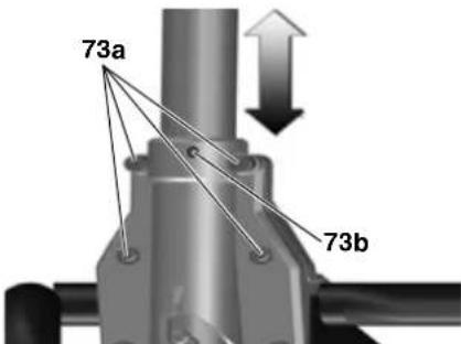
If necessary:
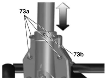
Set table leg guide bushings.
- Turn Allen screws (73a) clockwise = guide sluggish.
- Turn Allen screws (73a) counterclockwise = guide moves easily.
Further fine adjustment by means of a setscrew (73b).
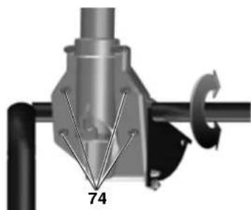
Setting guide bushings on front leg mount:
- Turn Allen screws (74) clockwise = guide sluggish.
- Turn Allen screws (74) counterclockwise = guide moves easily.

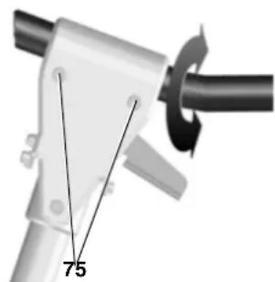
Setting guide bushings on rear leg mount:
-
Turn Allen screws (75) clockwise = guide sluggish.
-
Turn Allen screws (75) counterclockwise = guide moves easily.
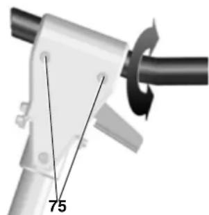
Tighten all Allen screws diagonally and evenly.
9. Tips and Tricks
- Before cutting a workpiece to size make trial cuts on pieces of scrap.
Always place a workpiece on the saw table in such way that it cannot tilt or rock (e.g. always place a curved board on the table with the convex side up).
To simplify repetitive cut-off work use a stock stop. - Keep surface of table clean.
10. Available Accessories
Use only genuine Metabo accessories.
Use only accessories that fulfil the requirements and specifications listed in these operating instructions.
For a complete range of accessories, see www.metabo.com or the catalogue.
11. Repairs
Dan
For safety reasons, repairs to power tools must be carried out by qualified electricians only using original spare parts!
If you have Metabo electrical tools that require repairs, please contact your Metabo service centre. For addresses see www.metabo.com.
You can download spare parts lists from www.metabo.com.
12. Disposal
Power tools do not belong in the household rubbish.
According to European Directive 2002/96/EC on waste electrical and electronic
equipment, used electrical devices must be collected separately and taken to an environmentally friendly recycling?facility.
Contact your local council for information on disposal of the used tool.
All packaging materials are recyclable.
13. Troubleshooting

Danger!
Before carrying out any fault service or maintenance work, always:
- switch machine off.
- unplug mains cable.
- wait for saw blade to come to standstill.
Check that all safety devices are operational again after each fault service.
Motor does not run
The restart protection is active. If the mains plug is inserted with the machine switched on, or if the current supply is restored following an interruption, the machine does not start up:
- Switch the machine off and on again.
No mains voltage
- Check cables, plug, outlet and mains fuse.
Motor overheated, e.g. by a blunt saw blade or chip build-up in the chip case:
- Remove cause for overheating, let cool off for a few minutes. Then restart machine.
Speed is not reached
Overload protection: There is a MAJOR reduction in load speed.
- The motor temperature is too high!
Allow the machine to run at idle speed until it has cooled down.
Overload protection: There is a SLIGHT reduction in load speed.
- The machine is overloaded. Reduce the load before continuing to work.
Specified maximum no-load speed is not reached - motor not receiving sufficient mains voltage:
-
use a shorter feed line or cable with larger cross section ( ≥ 1.5 ~mm^2 ).
-
Have power supply checked by a qualified electrician.
Loss of cutting performance
Saw blade blunt (possibly tempering marks on blade body):
- Replace saw blade (see chapter "Maintenance").
Chip ejection blocked
No dust collector connected or suction capacity insufficient:
increase suction capacity (air speed ≥ 20m / sec at chip ejection tube).
14. Technical specifications
| Voltage V 220 - 240 (1~ 50/60 Hz) | ||
| Wattage power input P1 power output P2 | kW kW | 2,00 kW S6 20% 1.27 kW S6 20% |
| Current draw A 9 | ||
| Fuse protection min. A 16 (time-lag) | ||
| Protection class IP 20 | ||
| Rated no-load speed (at 230V) rpm 4200 | ||
| Cutting speed (at 230V) m/s 57 | ||
| Riving knife thickness | mm | 2,3 |
| Saw blade | ||
| Saw blade diameter (outside) | mm | 250 - 254 |
| Saw blade diameter (inside) | mm | 30 |
| Cutting width | mm | 2.4 |
| max. base body thickness of saw blade | mm | 1.6 |
| Depth of cut | ||
| with saw blade vertical | mm | 0 ... 87 |
| at 45° saw blade tilt | mm | 0 ... 50 |
| max. cutting width with rip fence | mm | 630 |
| max. cross-section width with angle guide | mm | 200 |
| Dimensions | ||
| without machine stand (L x W x H) | mm | 740 x 750 x 355 |
| with machine stand (L x W x H) | mm | 790 x 945 x 850 |
| Length of saw table | mm | 670/970 |
| Width of saw table | mm | 715/995 |
| Machine weight with machine stand | kg | 33.4 |
| Noise emission values according to EN 61029 * | ||
| A-sound pressure level LpA | dB (A) | 99 |
| A-sound power level LwA | dB (A) | 112 |
| Measuring inaccuracy (KpA, KwA) | dB (A) | 3 |
| * Emission values Using these values, you can estimate the emissions from this power tool and compare these with the values emitted by other power tools. The actual values may be higher or lower, depending on the particular application and the condition of the tool or power tool. In estimating the values, you should also include work breaks and periods of low use. Based on the estimated emission values, specify protective measures for the user - for example, any organisational steps that must be put in place. | ||
Risque de happenment!
Installation sans support demachine:
Risque de happenment!
Risk for elstot! Risk for personskadorPGA ground avel.
Risk for indragning!
Sta pa ratt stalle under sagning:
Risk for indragning!
Handratt for skjareehoydeinnstilling
Still inn foringshylsene pa bordbeina.
Adresser pá www.metabo.com.
Du kan laste ned resveredelslister fra www.metabo.com.
12. Avhending
Adresserfindespawww.metabo.com.
Reservedelslicer kan downloads pa www.metabo.com.
12. Bortskaffelse
24 NaIpy6OK BbI6pOca OnIIOK
OrnabInne
1.0630p HhCtpyMeHtA
2. Hntatb B nepByo oupepeb!
3. TexHHa 6e3oNaCHOCTN
4. YctaHObKa
5. BbOaB 3HcNpyatauHO
6.3Kcnpnyataun
7. TpaHcnpOpbObKa
8. TexHnuechoe 06cnyHnBaHne n yxo
9. CobetbI npekomeHaauu
10.Пинадлжнocтн
11.PemOH
12. Ytuln3aun
13. Ipo6IeMbI H HeCNpabHocTH
14. TexHnueeChne xapaHTepnCTnHN
2. YntaB B nepByo oupepb!

IPEyPENKDEHNE!JIa CHNKeHHn pUCKa TpaBMPOBaHn npOHTITE pyKOBOcTBO NO 3K-
cnnyatau.
NPEyPENHEHNE! NpOHTte Bce HnCTpyKuHn UyKa3AHnnoTexHnE 6eONacHOCTn. HeBbIOJIHeHne INCTpyKuHn UyKa3AHnIO TexHnke 6eONacHOCTn MOKeT npVBecTu K nopAKeHNO 3JNeKTpuYeCKIM TOKOM, BO3RopAHIO WnIIN K NOUYeHNIO TJeKleLibx TpaBM.
CoxpaHnte Bce HnctpyKuN N yka3aHHNo TExHNKe 6eONaCHOCTN.
IpeepaBauTe HnCTpymeT CneDyIOUe My BnaDeIbCu TOJIbKO BmecTe C 3TNMM DOkymeHTAmN.
JaHHoe pyKOBOcTBo no 3KcNlyaTaun paCCHTaHO HaIIODe C6a-3OBbIMn TEXHnueCKHMn 3HaHnAIMn, Heo6XoDMbIMn dIpa6OtBICyCTPOINCTBaMn, IIOo6HbIMn TOMy, KOTOPOE ONNCbIBaETCnB DaHHOMpyKOBOcTBe.Ecn y BAC HET Obl-Ta pa6OtBIC TaHmN yCTpOnCTBaMn, Bbl DOJIKNbI CHaJlA BOCIOJIb3O-BaTbcr NOMOu bIO ONbITbIX CNEUaJIUCTOB.
IpoIN3BOIDNTeHHe Hecet OTBETCTBeHHOCTb 3a NOBpeKdEHN, BO3HNKWHne B pezylbTaTe HECo6HIODeHN DaHHORo pyKOBOCTBO NO3KcIIyatauN.
HΦopMaŋaO603HaueHa B DaHOM pyKoBOdCTBe No 3KcNlyaTaun CneDyIoum 6pa3OM:

Onachoctb!
PpeDynpEnHHe n6 onaChocn TpaBMnpoBaan Hnn BpeDe dna Okpyhaoue cpebl.
Onachoctb noIyehn TpaBM BCJeCTBHe yda- pa 3JeKtpnuechm ToHOM!
PpeDynpEckdHne 06 ONaCHOCTH TpaBMnPOBaHHa H npHa pa- 6oTe c 3JeKtpOo6OpdyoBaHHem.
Onachoctb 3axBata! PpeynpeHdene 06 onachoctn TpaBMnpoBaHHIIODe BCJeDCTBne 3axBata YacteN
TeHa HnN OeHdbI.

BHHMaHHe!
PpeynpeHdeHne 06 ONaCHocTH MaTeHnAbb Horo yuepe6a.

Yka3aHHe:
IOnoJIHnTeJIbHaI INΦOpMaun.
3. TexHHa 6e3oNaCHOCTH
3.1 NcnoJb3OBAHne no Ha3HaueHnIO
AaHHbI INHCTpymENT npeHa3Nauehen DnI npoDoJIbHOH IonepeuHOH paCNIOBKn MaccNBA dpeBeCINHbI, lamHNHPOBaHHoDpeBeCInHbI, DCn, cToJIpHbIX NINT I aHaIOnIHbIX MaTePnaJIOB.
Pe3kaMetaIaIaIOnychaTeTcToIbHO npn CneDyOuNX yCIOBnX:
HcNoIb3OBaHHe ToJIbKO NODXOJa- Ⅲero NIIbHOrO DnCKa (CM. «PpHaJNeKHoCTN»);
pe3Ka TOnbKO UBeTHbIX MeTaJIIOB (pe3Ka TBepIoro CnIaBa/3aKaJIeHHOroMeTaIIHa He DonyChaeTcR.
KpyIbIe 3aROTOBKn MOHNO nINITb ToIbKO C hCnOJIb3OBAHNEM NOxOJa- Iero npncNOC6JIeHn IA JI KCaUN, T.K.B pOToHBOM Cnyae TaKHe 3aROTOBKn MOrYT HaHaT BpaUaTbCBAcEJCTBNE BO3DeIcTBn HA HNX BpaAIO- UeROr NINlbHOrO DnCKa.
Ppi paCnHIOBKe PLOCKHX 3aROTOBOK, yCTaHOJIeHHbIX Ha pe6po, B CEJIAX IX 6e3OpanCHOI POJaH NHeo6XoIMO HcNoJIb3OBA Tb NOxOJaUyN yNOP.
3anpeaaetcHcnoIb3ObaTb daHHbIMNHCTpymENT bIyBbI6OpKn YeTBepTeN O6pa60TKn na3OB 6e3 nOxDxOJaUeTo 3aunTHOro npncnocO6JeHn.
He nCnoIb3yIte cIpyKUyIphIe nIIblI dI npope3aHH na3OB (npOIN, OKaHcYBaIOUncra BHTpN 3aTOrTOBKn).
JIIO6oe INHOe INCNOJb3OBAHHe ABJETcR IcNOLb3OBaHNEM He NO Ha3NaYeHNI. IpON3BOJNTeJIb He Hecet OTBETCTBEHHOCb 3a NOBpeKdEHH, BO3HNKUHe B pe3yJbTaTe HECOTBTCTBYIOUeRO INCNOJb3OBaHnI.
IpepeJIka daHnro HnCTpymeHTa nn IINcNoIb3OBAHHe DeTaJe, He npOBepHHbIX He pa3peWeHHbIX pOn13BODITeJEM, MOrT npNBecTN K HenpeDAK3ayEmBIM NocJeCDTBnM (TpabMaM, MaTePnaIbHOMy yuepe6y) B XoJe 3KcNlyatau.
3.2 06uhe yka3aHnno TExHHKe 6e3onacHOCTn
BnMaHHe!QTo6bI He dOnyctNtB no-paKaHeH3JIeKTPnuuecKIM TOKOM,TPaBM N OxOroB npn 3KcnnyatauH3JIeKTPoHNCTpyMeHTa Heo6Xdmo CO6JIODaT pINBOUMbIe 3deCb OCHOBHbIe npaBnla TexHKn 6e3onacHOCTN.
PnHcNoIb3OBAHH DaHHOro HCTpyMeHTa CO6JIIOdaIte CLeDyUOuJe yKa3AHn ITO texHnke 6e3Ona-CHOCTN, YTo6bl NCHIOHTB BO3HNKHOBEHHe ONaCHOCTn JIAIODeHm MaTePnaIbHorO yuepe6a.
CobioaTe cneuaIbHbIe yka3a-HnI IO TexNIke 6eONacHOCTn, npIBOIMBIE B COOTBeTCTByIOxN IGabax.
- Pn pa6oTe c npKyIpaHbIMn nIaMm Co6IIOaIte COOTBeTCTByIOuIe HnpeKTnBbl IIN npeDncaHnA NO npeDoTbpaueHIO HechactThbIX Cnyaeb.

Oe onachoctn!
CneIte 3a uNCTOToH nOpAekOM Ha CBOeM pa6oem MeCTe -6ecnopAOK Ha pa6oem MeCTe MoKeT npNBecTHK HeCCHaTbIM Cnyaam.
БудьтBE BHMaTeIbHb!CocpeToTOyTecbHaBbINOnHReMoI OnpaUuN.IoXoNDteKpa6OteOCMbIcJIeHNO.IpeKpaTIne pa6Oty CnHCTpyMeHTOM,ecnBacYTO-JIN60OTBLeKaet!
- YUHTbIbAaTe BO3dEeCTBnA OKpyKaHIOSeI cpebl. O6ecneHbTe xopoOo-ooceuHHe npaoyero Mecta.
He pa6oTaIe B HeyIo6hIx nO3ax. NocToaHHO CoXpaHaIte yCtouHn- BOe nIOJKeHne n paBHOBecne.
- PnO6p6oTKe DInHHbIX 3aToBOK NcNoJIb3yIte nOxDxJaune onOpbldHnx.
He nCnOJIb3yIte HNCTpyMeHT TaM, rDe cyIeCTByeT ONaCHOCTb NoKa-pa NII B3pbIbA.
3TOT INHCTpymEHT MOKeH TNCIOJIb3OBATcra TOIbKO TEMN IINaAMN, KOTOpbIe npoJIn INHCTpyKTKaH NO 6e3-ONaCHOMy O6paUeHNIO CUNPKYIaRpbIM NINJaAMN IO3HaKOMJIeHbIC BO3MOXHbIMN OAnCHOCTaMn, KOToPbIE MOrYT BO3HKnKaTb B XOde pa60TbIC HNM. JINiAm MnaDiue 18 let pa3peSwaETcRA NCIOJIb3OBAtB 3TOT INHCTpymEHT TOIbKO B pAMkx IpOpeccHOHaJIb-Horo 6oyehn I NOD HaI3Opom Ma
CTepa npOn3BOdCTBeHHOrO oBuHnI.
He donyckaIte noctopOHnHx - oco6eHHo deTei - B onachyIO 30Hy. He pa3pewaIte noCTOPOHHM IInaM npHKacatbca K HnCTpyMeHTy Nn erO cTeBOMy Ka6JIIO BO BpEMr 3KcNlyatauIN.
He donyckaIte neperpuy3HnHCTpymEnTa-NCNoJIb3yIeeroTOJbKO B TOM dHaana3OHe MOUHOCTN, KOToPbI yKa3aH B TEXHueCCHX XapaKTePcNTkax.

Onachocb ot 3neKtpoo6opy
DobAHnI!
He noDBepraIte HNCTpyMeHT Bo3-DeiCTBIO DOJXn. He nCnoJIb3yIte HNCTpyMeHT BO BJIaKhbIX NcbIpBX IOMEueHnX. Bo BPempa6oTbI CTapaIteCb He npHKacatbcra YactaMn TeLa K 3a-3eMMHeHM KOHCTpyKuYMa/3Je-MeHTam KOHCTpyKuYn (HaNPmep K 6aTapeA MOTOnlneHn, Tpy6aM, 3JIeKTPOPiNTAm, XOJOINbHNkAM).
IcnoIb3yIte cTeBOI Ka6JIb TOJbKO IIO Ha3HaueHEnIO.

OnachocTb TpaBMPOBaHnI
3aHnMa NOBnKhbIMn DeTaIaMn!
He 3KcIpyaTnpyTe 3OT INHCTpyMeHT 6e3 yCTaHOBJIeHHo 3aUHTHOJ OCHACTKn.
Bcerda co6IouaIte 6e0nacHoe paCToHne OT NlIbHoro DnCKa. Pn Heo6xOdMocTH nCNoIb3yIte noXoJaIne npncnooc6JeHnra Ina noDaun 3arotOBok. Bo BpempaBoTbI co6IouaIte 6e0nacHoe paCToHne OT pNBOIMbIX BDbNKeHne Detalei.
- PpeJde Yem ydaJIaTb n3 pa6OeH 30HbI o6pe3Kn 3aRTOBOK nT. n., DOxHNTECb NOHOBOCaHOBKn NINlbHO rNcKa.
He octaHaBnBaIte nIbHbI dNcK, Bpaauoosno Hepu,nytemero npHKMa c60ky.
-Перед повоздем Тхичеснх pa60у6eДNTeCbВTom,TOИСТPyм ent OTcoeINHeHOT3JIeKTPocetN.
IpeBnLIOUeHHeM INHCTpyMeHTa (HaNPIMep, nOcNE 3aBepSeHHa TExNHueCnIX pa6oT) y6eINTeCb B TOM, YTO BHYTpN HrO He OCTaIOcB HNKAKNX MOHTaKHBIX INHCTpyMeHTOB NII INHbIX OTdJIbHbIX dTeTaeI.
BbIKIOUaHTe INHCTpymENT,ecn OH He NcNoJIb3yETC.

OnacHoctb nope3a cyueCTbYHe npn HenoDbHHOM peHyMHCTpymente!
- ПизамеpeнушихИнстум entobнадебаite 3aunTHbIe nepuataKn.
XpaHnTe PnIbHbIe DnCKn TaK, YTO6bI NOHOCThbIO NCHJIOnHTb BepoTHOCTb TpaBMnPOBaHHa NM IIOJe.

OnacHOCTb BCJeCDTBne OTaTROBOK (3aROTOBKa 3axBaTbI- TINbHbIM DNCHOM N MOHET MTb ONepaTopa PnB Bpaue
Pa6oTaIe ToIbHo C npaBnIbHo OTpeYlnpOBAHHbIM packInHBAHO-UM HOHOM.
- PackHINHBAIOUH NOH HNCNoB3yEmbI INbHbI DnCK DOJHHbI NOXoDHT dpYr K dpyr: pacHINHBAIOUH NOH He DOJHKeH 6bITb TOIue WnpHbI npOuHa I He DOJKeH 6bITb TOHbE NOLOTHa DnCKa.
He donyckaTe nepeKoc3arotOBOK.
Y6eIITecbBTOM,HTOINHbHbIM NCK IOXoNT IJI O6pa6OTn MaTePnJa,I3 KOTOPOrn3rTOBHeHa 3aROTOBka.
ПИЛNTE TOHKNE/TOHKOCTEHHbIe 3a-ROTOBKN TOJIbKO C HcNOJIb3OBaHnEMПИЛbHbIX DnICOB C MEJIKNM 3y6bRmN.
Bcerda nCnoJb3yIe ToJbKO ocTpo 3aTOHeHbIe NJIbHbIe DNCKN.
B Cnyae comHEnoOcMOTpnte 3a- roTOBn Ha HAnuNe B HNX nocTo- poHHnx npEmdTeB (HaPnmeR TBO3de nn uypynob).
ПИNTTE 3aROTOBKN TOJbKO Tex pa3-MepOB, KOTOpBIE rapaHTnpyIOT HaN-EXHOCbФHKCaUN DeTaJIe B XOe PINJBbIX pa60T.
HaTeROpUeCKn 3anpeaaetcBblIOJIHrTb OndOBpEmEHHyIpaCNILOBky HECKOJbKHX 3aROTOBOK,B T.4.B C8ra3kax I3 HeCKOJIbKHX OTDeJIbHbIX WtYK.OnachocTb HeCyaCTHO rO CnyyA npH HeKOHTPOJIpyEMOM 3axBaTe OTdeJIbHbIX PpeMeTOB NIIbHbIM DnCKOM.
- YdaJIaIYeMeJIKe O6pe3Kn 3arOToBOK N.T. n. n3 pa6oey 30HbI
HbHbN DnCK Pn3TOM DOJKeH 6bITb HNOBnKeH.

Onachoctb 3axbata!
CneIte 3a TEM, YTO6bI BO Bpempa60TbI He DOnyCTnTb 3axBaTa Ya-CTeI TeIa HIN ODeHXbl BpaAuaOuHMMc DaTALIMN (He HAdeBaTe raIcTyKN, NepaATKn, OdeHdY cDHHbIMN pyHaBAMN;ДINHHbIE BOIOcbI y6npaIte NOd TOLOBHOy6Op/ceTHy dIraBOLOc).
Kateropnueckn 3anpeuaeTcnnIINb 3aROTOBHN,Ha KOTOpbIX/B KOTOpbIX HaxoJrTcN
- Tpocbl,
-UnHypbbl,
-JIeHTbl,
-ka6eHnHn
IpoBoJokaHaHaJIoTHyHbIeMaTePnAJIbl.

Onachoctb BCJIeCTBHe HeDo
CTaTOUHOrO OCHaSeHnCpeDcTBAM HNDNBHyalbHOH 3aunTbl!
IcnoJb3yIe 3aunTHbIe HayuHnKn.
Pa6oTaIeB3aunTHbIXOCHX.
IcnoJb3yIte nbIe3aunTHbI peCnnpaTOP.
Pa6oTaIe B cpeuaJIbHOJ OeJHDe.
- Ppi pa6oTe Ha OTKpbTOM Bo3dyxpeKoMeHdyETcHaDeBaTb 06yBb CHeckOJIb3aIe NODOWBOH.
- Pn pa6oTe CnnbHbIMn DnCKaMn n rpy6bIMn 3arOTOBaMn HcNoIb3yTe nepaTKn. NblbHbIe DNCHN nepenHOcHTBe B cyTlpe.

Onachoctb BCJeCTBHe dpen nbIN!
HeKOTOpbIe BnDbI dpBeBecHOI nbln (HanpImep DpeBecnHb Iy6a, 6yka n JaceHa) npn BdxhAHM MOrYT npINBOHTb K paKOBbIM 3a6OJIeBAHNm. Bcerda pa6oTaIte TOnbKO C NOkIIOUeHHo NblyeJaIauIOSe yCTaHOBKO. NblyeJaIauOJaa YCTaHOBKa DOJHKHa COOTBETCTBOBaTb npaMeTpam, yKa3aHHbIM B TexHInueCHNX xapaKTepNCTnKax.
- Y6eIITecb B TOM, YTO BO Bpempa-60TbIBO3dyx IOnaJaET MHNMaJIbHOe KOJIHcEChBO DpeBeCCHIN:
-yaJIaIYe cKoJIeHnI dpeBeCHOI PbInn B pa6OeY 3OHe (Hec dyBaITe!);
-ycTpaHnTe MeCTa HerepeMeTHUHOCTN B IIyEuaIIOuSe yCTaHOBKe;
-06ecnebyTe xopooyu BENTnla- cyu pa6oey 3Ohbl.

Onachoctb BCJeDCTBHe Tex-
Hnuechnx H3MeHeHH Nn HCNoJIb- 3OBaHHaTeTaJIe, He npOBepEHbIX n He pa3peWeHHbIX npON3BOAnTeJIem
MOHTIpyIe 3OT INHCTpyMeHT B TOCHOM COOTBETCTBUN C DaHHbIM pyKOBOCTBOM.
IcnoIb3yIteToIbKOpa3peWeH HbIeN3rOToBnTeJIemDeTAlN.B YactHOCTN,3TOKACAETC:
- NIIbHbIX DnCKOB (KOdbI ⅡIa3aKa3a CM. B pa3dene «Прнан-ЛeHHOCTN»);
3aUHTbIX yCTpoiCTB (KoDbI nJa 3aKa3a CM. B CnICKe 3aNaChbIX qacte).
HepeeJIbIbAIteTeIaII.

OnachocTh BCJIeCTBHe De
ΦeKTOB INHCTpyMeHTa!
TuaTeIbHo yxaHnBaIte 3a INHCTpyMeHTOM,a TaKHe 3a npHaIeJHKHOCTaMn.Co6JIoDaIte IpeDnCaHnIPO TexHnEChOMy O6ClyKnBaHnIO.
KaHdbpa3pepdHaayanompa60TbI npOBepnTe IHCTpyMeHT HaOTCYCTBNE BO3MOHHbIX NOBpeKHeHNI:peed DaJIbHeNIMNCNOJb3OBaHNEM INCTpyMeHTaCNeDyET TuaTeJBHO npOBepNTbnpABINbHyIO 6e3ynpeHyIO pa6O TY npEOxpanTeJBhIX yCTPOiCTB,3aunTHoOchAcTKn,a TaKHe Detale,NMEIOUX He3HaHTeJBHbieNOBpeKDeHry.Y6eHTecB B OTCYCTBNI 3aHINHBaHNI IOBpeKHeHNI pONBHKbIX Detale.Bce DetalN CneDyET npabINbHO MOHTIpOBaTB N BBINOHNITb BCE YcIOBNIo ObecneHIO 6e3ynpeHoi pa60TbIHCTpyMeHTa.
IobpeHHe He TaII Nn 3a-
THA OChactKa NoJNeKAt peMOTy IIN 3aMeHe B CneUaN3IpOBAHHo (ABTOP3OBAHHO) MacTePcKO. 3aMeHy NOBpeHDeHbIX BbIKIOHaTeJIeO CyUeCTBJIrTe Uepe3 cepBnCHyIO MaTePcHyIO. He HcNoJIb3yIte 3OT INCTpyMeHT
B Cnyuae HeNCnpaBHOCTI eRO BblKIIIOUaTeJI.
3amacneHHbIe pyKoRTn HemeJeHHO OUNaIte: OH NdoJIHHbI 6bITb cyxIMN uHCTbIMN.

Onacnoctb BCJIeCTBHe wyma!
IcnoJb3yIe 3aunTHbIe HayuHNH.
- Y6eHITecb B TOM, YTO paCHINHIBaIOUH HOK He DeΦOpMnPOBaH. DeΦOpMnPOBaHHbI paCHINHBAIOUH HOK PnIKHMaET 3aTOrOBky C6OKy K INlbOMy DnCKy. 3TO Bbl3bIAeT NOBHeHne UyMa.

Onachoctb BCJeDCTBne 6I0BaHHa3aTOBOK HIN INX 4a
YTo DeIaTb B Clyuae 6IoKInpOBKn:
- BbIKHIOHTb HNCTpyMeH;
- BblHyb BNJIHy n3 pO3eTHn;
- NaTeb 3aunTHbIe nepaTkn;
- yctpaHbTb npuHnHy bLoHnpOBKIn C NOMOJIbIO NOxOJaIeTO INCTpy-MEHTa.
3.3 CnMBOJIbHa HhCTpyMeHTe
AaHbIe Ha 3aBODcKo Ta6JnUHe:

(25)ПОНИВОДИТЕЛ
(26) CepnHbH HOpE
(27) 06o3HaHeHne HnCTpyMeHTa
(28)ДаHHbIe DBHraTeJIa (cM.TaHKe «TexHnueChne xapaKTePncTnKn»)
(29) Mapknipobka CE - 3TOT nHCTpyMeHT OTBeHaET Tpe6oBaHnRm DnpeKTHB EC corlaCHO DeKla-paunu COOTBETCTBnA
(30) CnMBoI yTInH3aUIN -yTInH3a- UIN HCTpyMeHTA BO3MOXHa Hepe3ΦnpMy npOn3BODntEJI
(31) TODn3rTOBNEHIN
(32) Pa3mepb1 pa3peHHeBIX K 3KcNJIyatauIN NIIbHbIX DnCHOB
3HaH6e3OaCHOCTN

Onachoctb! Heco6IIOeHne cIeDy IOuNX npEduynpeJeHN MOKeT pINBecTu K TReHeBIM TpaBMam Nm MaTePnaIbHOMy uep6y.

IpoTuTe pyKoBOdCTBO nO 3KcNlyatau.

He 6epntecb pykamn 3a Bpaauoouncra nIbHbI DNCH.

Hocnte 3aunTHbIe OCHN H3aunTHbIe HayuHNK.
He 3KcnnyatnpyTe HCTpyMeHT BO BnaHbIX INCBipbIX NOMeueHnX.
3.4 3aunTHbIe npncnoco-6JeHHa
PachJIHHHbOUsH HOK
PacnHbAooH HOK (33) npdoTbpaaet 3axBaT 3arotOBKn 3y6bAMN BpaauoecOra NllbHO Dncka H ee OTJeTaHne HnnpaBHeHH onepaTopa.
BoBpempa6oTbIpaKlnHBAUoiH HOXdoJIKeH 6bITbBCeRda CMOHTnpoBaH.
3aunTHbH KOHx
3aunTHbIK KOHyx (34) cnyHIT dIg 3a- uTbI OepaTopo ATcIyHaHOrO co- npNKOCHOBeHnC nIbHbIM NCKOM I OTJIeTAOuX ONIOK.
Bo Bpempa60b3aunTHbI KOxHy DoJIKeH 6bITb BCERda CMOHTnpoBaH.
Tonnareib
TolkaTeIb (35) clyHHT B KaueCTBe ydJIINHHTeIbHoro 3nemeHa dIg 6eONa-CHOrO IporoHa 3arOTOBu YpeE3 NHBi DNCK n DIAaHTbI OepaTopa OT ClyuAHorO KOHTaKTa C NlbHbIM DNCKOM.
ToIkaTeJIb DoJIKeH NcIOJIb3OBAtbcra BcERdaBTEX CUYaX,ecnIpaCToR-Hne MeJyNIIbHbIM DnCKOM nnapaJIeJIbHbIM yIopom COCTaJIaET MeHee 120 MM.
TolkaTeIbdoJIOJIeH yCTaHaBJIuBaTbcn NOyrgIOM BdVana3OHe o 20^ do 30^ OTHCHTeIbHO NOBepXHOCTn CToJa.
EcnToHataTeB He NcNoIbayetc,ero CJeNyET XpaHHT BMeCTe C HnHCTpymEH- TOM.
PnIOBpeKdEHHToKaTeIeeroCne dyET 3aMeHHTb.
4. YCTaHOBHa

NoctoHHo coxpaHnTe
yctOuHBOe NpOHeHne npaBHOBeCne.
YctaHOBha 6e3 CTAHHbI:
- N3BJIeKHTe NIIy BINOEM C NOMOJIHINKOM H3 YNAKOBNI.
- YCTaHOBnTE NmNy Ha HEnoDBNHHoe OCHOBaHHe (CToI HIN Bepctak).
- Ппвернite плу К осованio (сту ль Всртак).
YctaHOBka CO cTaHnHOI:
- N3BLeKHeIHHCTpymENT BDBOEM C NOMOuHnKOM IyNAKOBN.
- YcTaHOBnTe INHCTpyMeHT HaNoI.
- ПОДНМЛТЕ ИСТРМЕNT 3a pyKoTKNИ YCTaHOBITe Ha pe6po.
- BbTnHTe pyKoTKn (36), NOBepHnTe n 3aФнСчуп Te nx.
- Pa3IOKHe 06e HNHNX ONOpHbIX HOHH.ДЯ 3TOrO pNKNMITE BHN3 KpaCHbIe pbHaKKn (37) (HOrONy pyKo) nOTBeINTe HOHHBHN3.
- CJIeRka HaKIOHnTe HNCTpyMeHT Ha3aI npINKMnTe OBe HOXKN BHN3.KpaCHbIe pbIaXKn (37) DOJXHbI3aΦHKcIpOBAtbcra.
- Pa3IOHnTe 06e BepxHnx OnOpHbIX HOHH. IJIa 3TOr CdBnHbTe Kpa- CHbIe pbHaKKN (38) BnpaBO N OTBe- DHTe HOHH BHN3. KpaCHbIe pbHaKKN DOJHKbI 3aФHKCnPOBaTcR.
8.Bo3bMnTe nIy 3a BepxHIO pamy no ceHTpy.PnpnoDMnTe nNoCTaBBte nIy (peYlnpyEmyHOHK Ky npndepKnBaNTe HOrO, YTO6bl NCHIOHTb CMeueHne INHCTpyMeHTa npu yCTaHOBKe).
- BbipOBHnIe HepOBHocTHOcHOBaHHN C NOMOuBpeyIpyEmoHOKK (39).
5. BbOaB 3Hcnpnyatauio
5.1 MoHTaX
PachJIHHHBAOUsN HOK

Yka3aHHe:
PacnHnBaOuH HOH npn oocBaKe C 3aOda yke Hactpoen DOJIHHbIM o6pa- 3om.Ero perynipOBKa npn BBoJe IHCTpyMeHTA B EKNIyatauHOe6XoJMa JINb B TOM Cnyae,ecnI NOIOXeHHe HOHa N3MeHNIOcb BO BpeM TpaHCnpTIpOBKn NJIbl.
- POnHmNte nIbHbI dNcK do yNo- pa BBepx c NOMOuBIO KpNBOUINHOI pyKOaTKn.
- BbIeBpHnTe BnHT (40) npOTnB yacoBOI CTpeKN, pnpOoHmNte N 3- BNEKHTE BCTaBHy CToJa.
40
- Pa36IoknpyTe cTOnOpHbI pbUar (41) (noBepHnte npOTnb YacOBoi CTpeHN!.
- BbITAHTE paKINHBAIOUH HOK (42) IN3 HNHHero NOIOKeHnI DJI TpaHCnOpTIpOBKn Do ynpa BBepx.
- Поберka npabINbHOro noIOJHe- HnI paKInHnBaUcero HOHa:
PacctoHHe OT HApyKHOH KpOMKNINbHO Dmcha Do paCKINHVAHOe HOHa DOJIHKHO CoCTABnTb ot 3 do 5 MM.
-PachINHBAOUH HOH DOLHE6bITb yCTaHOBJIe H COOCO C INJBHBIM NCKOM.

Onachoctb!
PacHHHBAIOH HOK OTHOCNTCA K 3aunTHbIM npncnoc6neHnM IN B ueJAX 6e3onacHOKcnIyatauHn HNCTpyMeHTa DOJIKeH 6bITb yCTaHOBHeH npabINbHo.
Pn Heo6xOaMocTpeyIuPoBKn noLoKeHn paCHINHbAIOUero HOka:
- Pa36IoknpyTe cTOnOpHbI pbUar (41) (noBepHnte npOTnb YacOBoi CTpeHN!.
- Perynipobka packnHnHaOeero HOka (42) no BepTKaJI: pacCToHHe OT HApYKHO Kn KpOMKn NlNbHOrO DnCKa Do paKlnHnBaHO
HIOHOJONKHO COCTABTbOT 3do5MM.
- 3a6loKpyte cToOpHbI pbUar (41) (noBepHnte no yacoboi CTpeJIke!).
Bokobar perynpoBka:
pachNINHBAIOUH NHOX (43) nNHLbH
DnCK DOJIHHbI 6bITb yCTaHOBHeHc COO
CHO dpyr dpny. - BbIeBnHTe TpN BnHTa C BHyTpEH HMM WecTHnpaHHNKOM (44).
5.BbipoBnIte paKJIINHBAIOUH HOX (43) NO OHOH OCH C NIIbHbIM DnCKOM.
- 3aTAHHTe TPN BnHTa C BHyTpEHHM WecTNrpaHHNKOM (44).
- 3aKpEnIte BCTaBky CToJa n 3aΦnK-CnpyTe ee BNHTOM (40).
YctaHObHa 3aunTHoro KOHyxa
- POnHmnte nIbHbI dNcK do ynpa BBepxC NOMOuBIO KpNBOUINHOpyKoATrn.
- CMOHTnpyTe KOxHy (46) Ha nepeHHeM KpeJIeHN y paKInHbAioUoero HOka (45).
- 3aTAHHTe KOHXy C nOMOuBHO 3aXHMHOro pbUra.
5.2 PoiKJIoueHne K cetn 3/ nHTaHn

Onachocb! 3neKtpnuechoe
HcnoIb3yIte HnCTpyMeHT ToJIbHO B CyXnx NOMeueHHx.
IoKIOUaTe HCTpyMeHT ToJIbHO K TOMY NTOUHNHY NTaHnH, HOTOpBIO NTBeuaET CLEyIOuHM Tpe6OBAHnM (CM. TaHHe «TexHHueCHe XapaHTepNtHn»):
-po3eTN HndJeHauM o6pa- 30M yCTaHOBHeHbI, 3a3EmJIeHbI n npOBepeHbI;
HapnepHe H qactota CeTH 3JIeHTponHTAHN COOTBETCT BYOT npaMeTpam, yka3AHbIM Ha 3abODCHO Ta6nue HnHCTpymEHTa;
-3aunTa HNCTpyMeHTa Ocy- 电CTBnRETCn NOMOu bTO AB TOMATA 3aunTbI OT TOKa YTeH KMaHC.Ha 30 MA.

Yka3aHHe:
B Cnyuae BONPOCOB OTHOCHTeIbHO TORO,OTBeyaet IIN BAa66bITOBa 3JeKTPoCeTb DaHHbIM ycIOBnM, 06paauaTEcB CooTBETCTBYIOU OprHn3aunO 3HeproC6bTa HIn K CneuaJIncTy-3JeKTPnHy.
IpoHnaBbAte ceteBOH Ka6eJIb TaHIM O6pa3OM, YTO6bl OH He MeuAn npn pa6ote H He 6bl NOBpeHdeH B XOe EHCnlyaTa-uuHn HnCTpyMeHTa.
PepoXpaHnTe Ha6eB ot Ha- rpeBa, Bo3eNCTBnA arpeccNB HbIX HnKHOCTe N KOHTaC OcTpbIMn KpOMKaMn.
B KaueCTBe ydHnHInTeIbHorO Ka6eJIa HcNoJIb3yIte ToJIbKO Ka6eJIb c pe3HHOBn H3OJIaCne I cdoCTaTOUHbIM CeHeHNEM (CM. «TexHnueChne XapAHTePepntKNI»).
Pp pa60ax BHe nomeueHn HcnoIb3yIte ToIbHO pa3peuH HbIe K 3HCnIyatauH yDInHHTeNbHbIE Ka6eHN C COOTBETCTByIOSe MapKnHPOBHO.
PnOTcoeHHeHH CTeBOB BUNH OT PO3ETHN 3JIeKTPocETN He TAHHTe 3a Ka6eJb.
He donychaTe HenpeHaMepeH Horo nycha: nepeTem KaH BCTaBNTb BNky B po3eTHy y6eH-TEcb, 4TO BblHIOuateIb HHcTpymeHTa BblHIOueH.
6.3KcnpyaTaun

Onachoctb HecuaactHoro cIy
Ha npnyrnapno nne doJnKeH pa- 60taTb TOnbHO OINH YeNoBek. Dpyrne Nua MoryT npNBLeHaTbc K pa60te TOnbHO IINoDaun HIN CHaTH3arOTOBOK, HaxOJaCb npN 3tOM Ha 6e3onachom pacCToRHH OT NIIbl.
Ipeed hauaIom pa6oTbI npOBepbTe HcnpaBHOe COCTOHNHe CNeDyIOxH 3JIeMeHToB IHCTpyMeHTa:
- cTeBOH Ka6eIb N cTeBaB BnJIHa;
-BbIKJIIOuATEJIb;
-packKlnHnBaIOuN HOK;
-3aunTHbH KOHyX; - donolnHtBhIe npncnoc6JIe Hna Ipaau 3aROTOBOK (ToIHaTeIb, naHa n pykOHTHa).
HcnoB3yIte cpeIcTBa HnDnBHy-aIbHOI 3auNTbl:
- nbIe3aunTHbI peCnnpaTop;
-3aunTHbIe HayuHHKn;
-3aunTHbIeOCHN.
PnBbINOJIHeHn NIIbHbIX pa6OT npMNTe npaBnIbHoe pa6Oee noJIOKeHHe:
-cnepeynHa pa6oeycstopohe;
JIHcOM HIIJIe;
-cIeBa nOcHnnIbHOro IuCha;
- npn pa6oTe BdBoeM nomouHH dOJIKeH HaxoHTbc Ha 6e3ona- CHOM pacCToHHN OT NJIbl.
B xode pa6oTbI no Mepe Heo6xOuMoCTn HcNoJIb3yJTe:
- noDxOJaune Oonpbl dIy 3arotOBHN -ecnI nocIpe paCNIIOBHN 3arOTOBH MOrYT yNaCTb co cToJia;
-yctpoCTBOIaOTCacbBaHnONHIOK.
N36eraTe TnHbIX Oun6ok one- pataropa:
He octaHabnBaIte nIbHbI nnck, Bpaauounncr no HnepuHN, nytemero npHHMa c6OHy onachoctb otdaH!
B xode nIJIeHnB Bcerda npHHMaIte 3aROTOBHy K cTOny HneDONYcHaIte ee nepeHoCA - onaCHOCTb OTdau!
-Hateropnueechn 3anpeuaeTcBbIOJIHrTb OJHOBpeMeHHyOpacnIIOBHy HeCHOJIbHnx 3aROTOBOK,B T.4.BCB3HAX N3 HeCHOJIbHnx OTdJIbHbIX WtYK.OnaCHOCTb HeCHAcTHORO CnyyA npHeHOHTpOJInpyEMOM 3axBaTe OTdJIbHbIX PpeDMeTOB NIIbHbIM DnCKOM.

Onachoctb 3axBaata!
HaTEROpHueChn 3anpeuaeTc nHnHTb 3arOTOBKN, Ha KOTOpbIX/B KOtOpbIX HaxOJaTc TpOcbI, HHypbl, IeHTbl, Ka6eN nn npoBOJOna nn noDo6HbIe MaTePnaJIbI.
6.1 YctaHOBbA dIy ydaJIeHnOOnJIOK/yHNBePcAlbHbI nblncoc

Onachoctb!
HeKOTOpbIe BnDbI DpeBecHoi nbln (HaNPmep dpBeBecHbI dy6a, 6yha n rceH) npi BdbixAHnn Moryt npiBODntb H paHObblm 3a6OJIeBaHnM. Ppi BbINoHNHeHH pa60 BHTpn 3a-KpbITbIX NOMeueHn O6raTeJbHo NCNoJIb3yIte NpOxDOnA7UO yCTaHOBHy dIydaJIeHH ONILOK. 3Ta yCTaHOBbKa DOJIHHa OTBeuATb CJeDyIOUM Tpe6OBaHnM:
- NOxOHTb H dAmEtpy BbITAHbIX NaTpy6KOB (3aunTHbH KOHyx 38 MM; ONNKnOpnemHH 35/44 MM);
- pacxOa BO3aYxa ≥ 460 m³/4;
pa3peKeHHe B BbITaHHOM Na-tpy6He HnctpyMeHaT ≥ 530 Na; - CHOPOCb BO3dUshoro NtOHa B BBITAAHOM NaTy6Ke Nnbl≥20 M/c.
NpTy6Kn PbIeOTcOca paCNOJIeHbI Ha 3aUHTOM KOJyXe NIIbHOrO DNCKa HHa 3aUHTOM KOJyXe IJRA OTBODa ONIOK.
Takke co6bIoudaTe pykoBODCTBO no 3KcNpyataun yctaHOBKn Iy ydaJeHnna OOnJok!
3Kcnpyaataa nIbI 6e3 nCnoJIb3OBAHnYyCTaHOBKnIy ydaJIeHnN OINIOK pa3peWaeTcTOJbKO BHe NOMEueHn.
6.2 PerylnpoBHa rIy6HbI npoHla

Onachoctb!
Yactn Tea Hnn npedMetbI, HOTOpbIe HaxoAITcB 3OHe peryNIpOBHN, MoryT 6bITb 3axBaueHbI Bpaa
IOUHMCA NINbHbIM DNCHOM!
PeryIInpOBHy rIy6NbHb I npOnnla BblONHnTe TOLbKO npN OIoHOCTbIO
OCTaHOBJeHHOM NINbHOM DNCKe!
Iy6Hny npoHnla nHbHoro dNcHa He06xOIMO OtperyLnpoBaTb NO BbICOTe 3aROTOBHN: 3aunTHbI KOHX CBOEHNKHe NpeDHe KpOMKo DOJIKeH npIneratb K 3aROTOBKe.
Otperynpyte rny6nHy nponna nocpeidCTBOM BpaueHm MAXOBnka (47).

Yka3aHHe:
B CEJIAX KOMNeHcaUN BO3MOKHO 3a3opa npn peryInpOBHe rIy6HbI npOnHa CMeaAte NIIbHbI dNCH B HxHoe NOIOKeHne BCerda CH3y.
6.3 PerylnpoBHa HAnJHOHa NnIbHOrO nCHa

Onachoctb!
Yactn TeNa Hnn NpeMetbI, KOTOpbIe HaxoAITcB 3OHe peryNIpOBKN, MoryT 6bItb 3axBaueHb I BpaauIOUIMCn NlNbHbIM DNCKOM! PeryNIpOBHy HAnIOHa NnIbHoro DnCKa BblONHnTe ToJbHO npIN OJIHOCTbIO OCTAHOBnEHOM NnIbHOM dncke!
HaHIOH NIIbHoro DnCKa MOxHo peryIINPOBaTb B DnAna3OHe MeXy -1,5° n46,5°.
-
Pa36IoknpyIte 3aJHMHoi pbIuHa (48).
-
OTPeryIpyTe HxKbHnHaKIOH NIIbHO DnCKa.
3.3aФИКСИРУTe yCTaHOBJIeHHbIy yroJHaKIOHa nYTEM 6LoKINpOВKN 3aHIMHOro pbHara (48).
MaxobnK npernynpOBn Rny6nh nponna
Iy6Hny npoHnla MoHHo HAcTpoNTb C NOMOsbIO MAXOBnKa (49).
3aHMMHO pyuar npeynpobKn yraHa HAnloHa
Ipyempa36IOHPOBKN3aHHMHOPObIyara(50)MOHHOpeRyINPOBaTbHaKIOH NnIbHOrO DnCKa B DnAna3OHe MeKdY- 1,5°n46,5°.
TTO6b3aadHbIyroHaKaHOHa He H3MeHraCBO BpEmnHeHn,ero CLeDyET BHOBB 3aΦHKcPOBaTb C NOMObu 3aKHMHO pblara (50).
PyuHa-nepeKluOaTeIb dIyynopa npn HauHIOHe
He nepeHocHTe HnCTpyMeHT 3a 3a- uTHbIe npncnoc6JIeHH, paun
peHne cToIa Hn 3a 3JIeMeHTbl ynpabLeHHa!
TpaHcnpTnPOBbA B CLOXHeHHOM BnDE:
BbITAHHTe pyKoTHy, NOBepHHTe 3aΦHKcpyuTe ee.
TAYHITe HIN nepemeeuaTe nny 3a pyKoTHy.

PnnepebcInHe NO B03MOHHOCTNIOJIb3yIteOpINHaJIbHyO yNaKOBHy.
8. Texn Hec Hoe o6cnyHnBaHne n yxOa

Onachoctb!
Ipeep npoBeeHem IIO6bIX pa6OT NO TEXHNuecHOMy O6CJyKHBaHHIO uOCHTE:
- BbIKIOUHTe HNcTpymeHt.
2.ДОнТECb NOHOB OCTAHOBKNIJIbl. -
BbInbTe BnIky n3 po3eTHN.
-
Pocne KaKdoYcTpaHEnH HenCnpaBHOCTe BHOb bAkTHBpyIte N npOBepnTe BCE 3auHThble pniCnocO6JIeHn.
IIOBpeHdeHbIe DeTaN, B YacCTHOCTN 3aUHTbIe npncnOc6JeHna, 3aMeHnTe TOJbHO Ha OPUNHaJIbHbIe, T. K. NcNoJIb3OBAHne DeTaJIe, He IPOBepEHbIX H He pa3peHHeHbIX N3ROTOBNTeJIeM, MOKeT PnPBecTHK HEnpeDcKa3yEmbIM NocJeCDCTBNAM.
OncaHbIe B HactoIeM pa3deIpepa6tI NO Texo6cnyKuBaHnIO npemOTy DOJIHHb I BblONIHrTbCrtToIbKO CneuaNCTamN.

OnachocTb!
B clyuae noBpeHdeHn BCTaBn CToJa cyueCTByet OnaHocTb 3a- HInHHBaHH MeHNx PpeMeTOB
MeHdy BCTABHOI NIIbHbIM DN-CHOM HAH CJIeDCTBHe, 6JIOHNPOBKa NIIbHOrO DnCHa. HeMeJeHHO3aMeHrTe NOBpeXdEHHbIe BCTABKIn cToJa!
8.1 3aMeHa NJIbHOro IINcHa

Onachoctb!
B TeueHne KopoTHoro BpeMeHn noCne 3aBepWeHH pa6oTbI NIIbHbI dNCH MoKET OCTaBaTbCraNbHo HaRpeTbIM — OAnachOCTb Okora! DaTe OxJaNTbCRA HarPeTOMy NIIbHO My dNcHy. He OunuAte NIIbHbI dNch TropouHM HNDIOCTMn. OnachOCTb TpaBMnpOBaHH (nope30B) cyueCTByET n npn HenoDBHHOM NIIbHOM dNcHe. PpN 3aMeHe NIIbHOrO dNcKa HOcHTe 3aUNTHbIe nepuATKn.
PnC6OpHe 063aTeIbHo yuHTbIBaTte HAnpaBLeHne BpaSeHnIINbHorO ncha!
1.ПОДНМЛТЕ ПИЛБНД ДИСКdoунopaBBepxC NOMOULTIO KPNBOUHNOHpyKoTKn.
2. CHIMNTE 3aunTHbI KOHx.
3. Pa36JokHyIe N n3BJeKeHITe BCTABky CTOna (64).
- NOBOPaHbAInTe 3aKHMHyO raKy (68) c NOMOuIbIraeHOrO KJIoua I OJHOBpeMeHHo TAHnTE pbHaR φHK Caunn NINbHOrO DnCKa (65) BBePx Do Tex Nop, noka OH He 3aΦHKnPyetc.
- 3aKmnte pbyar n OTBepHnTe 3aXMHyIO raHy B HappaBHeHH No YacobO CTpeKe.
- CHIMITE 3aHHMHy IO raHy (68), HapyKHBn ΦIaHeu IJI KpeIJIeHIN NIIbHO DnCKA (67) INIIbHbN DnCK C Bala IJIINbHO DnCKa.
- OuHCTHTe 3aKHMhIe NOBepxHOCTn (66) n (67) pHaHca dIg KpeJIeHnI IINbHOrO DnCKa n OUHCTHTe NINbHbI DNCK.
Onachoctb!
He hCnoIb3yIte CpeIcTBA OChTn (HAnpImep, IaI ydaJIeHNIOCTaTHOB CMOLbl), HOTOpBle MOrY TNOBpeINb IerKocNJIABHbIe MetaJIInueChne DetAII; B IpOTNBHom Clyuae BO3MOHO yxUdWeHne 3KcNlyatauHOHO HAdEHHOCTNIJbI.
8.HacaIte BHytpenHnHnФlaHeu (66) IaKpePJIeHnIINbHOrO DnCKaHa BaI dBNraTeJ.
9. YcTaHOBHTe HOBbI NIIbHbI dNCK (co6JIOpaIte HAnpaBHeHne Bpaue-Hnra!.
Onachoctb!
NcnoB3yIe ToJIbHO NnIbHbIe DNCKH, COOTBeTCTByIOUJHe TExHHueCHHM XapaHTepnCTnHAM n CtaHdapTy EN 847-1 - B cnlyaeNCNoB3OBAHN HEnoDxOJnXnNIOBpeHXDeHHbIX NIIbHbIX DNCHOB NOI DeIcTBnEM cHTpo6HHO CNJIb BO3MOKHO pa3JeTaHne
OCHOHOB.
3anpeaaetcncnoB30BaTb:
NINbHBe DNCHM, MaCHMaJIbHO DONYCTHMaJyAcTota BpaUeHHa HOTOpbIX HnKe HOMHaJIbHOJ CaCTObl BpaUeHHa BaJa NINbHOrO DNcKa Ha XoIOCTOM XOy (CM. «TexHueChne XapaHTepnCTnHN»);
NIIbHbIe DNCHN H3 BbICOHOJIerHPOBaHHo6bICTpopeHyuue cTaJn (HS/HSS);
- NINbHbIe DNCKH, WnPnHa npOnnHa HOTOpbIX MeHbIe HJN TOUHHa NOJIOTHa DNCKa KOTOpbIX 6OJIbIe ToUHbI paCHJIINHBAHOuero HOHa;
- NINbHbIe DnCHN C BNIMbIMN NOBpeKdEHHaM;
-0TpE3HbIe Kpyr.
Onachoctb!
-Montpyte NnIbHbI DNCH TOIbHO C HcNOJIb3OBAHHem OPHINHaJIbHbIX DeTaeJ.
-He nCnoJb3yIte ocla6JeHHbIe nepexoHbIe KOJIbca;B npOTNB-HOM Cnyuae NIIbHbI INCH MoKcET COPBaTbCra.
- NnHbHbIe DnCHN DOJHHbI 6bITb CMOHTnPOBaHbI TAKHM O6pa3OM, YTO6bl OHn pa6oTaJIH 6e3 DnC6aJaHcA H6HeHr Hr MeMOrJn COpBaTbcra MeCTa KpePJIeHrB XOJe pa6oTbI.
10.HacaTe BHeuHnIeAeU (67) 1nKpeJIeHnIINbHOrO nCka.
11. HabepHnTE 3aHHMHyO rAHy (68) (JIeBaI pe3b6a!). NOBopaunBaIte 3aHHMHyO rAHy (68) C NOMOuBIO raeyHoro KIOHa I ONDOBpeMeHHO TAHNTE pbHar fHKcaUN (65) NHlbHOro Dncha BBepx Do Tex nop, nOKa OH He 3aΦHKcHpyETCJ.
12.3aФнсруtepbuHn3aTAHNTe 3aHHMHyraHny npOTNB YacOBO BCTpeKN OTpyH.
Onachoctb!
-
He ydHnHnTe HnCTpyMeHT, nCnOJb3yEmbl dIa 3aTARHBaHHnHbHorO dncka.
-He 3aTARHbAte CTAXHOB BNHT, ydapraNo HHcTpymeHTy. -
OTPeryIpyIte paCKHINHBAIOU HOK B COOTBETCTBUN Cpa3MEpOM NINbHOrO DnCHA (69)
(ONHcAHne perynnpOBKn paKlnHHBaOuIero HOXa cm. n. 5.1).
14.3akpenTe BCTaBky cToJa.
15.3aKpeNITe 3aunTHbI KOHx.
8.2 PerylnpoBka orpaHnUy npopa
- Otperynpytepbuvar-orpaHnTenbynopa(71)Ha 0^ / 45^
72
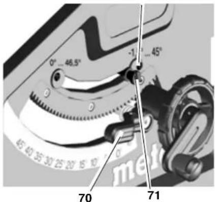
2.3aФИСИРУTe yCTaHOBJIeHHbIy yrOJ HAcIHOHa IYTem 6JIOKINPOBKN 3aHIMHOro pbHara (70).
3. PpOBepka yrna HAnHOHa:
0° = nepnEHNHUYIaRHO NINbHO- My CTOJy
-45°COTdEJIbHbIMYrOJIbHNKOM.
EcIN 3TN 3NaueHn yCTaHOBHeHbI HETOHO:
4.BbBepHnTe BnHT C KpeCToo6pa3- HbIM WInuem (72) Ha COOTBeTCTByIOUeM 3KcEHTpNKe NOTpeYIpynte 3KcEHTpNk TAK, YTO6bl yrOHaKHOHa OTHOCHTeNbHO NINbHoro CToJa B KOHeuHbIX NOLOXKeHHx CoCTaBnT ToH0 0^ (= nppeHnkyIapHo)nn 45°
5. CHOBA 3aTAHHTe BHTc KpeCToo-6pa3HbIM WnIcEm Ha 3KcEHTpNIke.
6. Nocle perylnpOBKn orpaHnHTeY npa nHeo6xOaMnOCTn DOnoJI HntelbHO OTperylnpyTe yrLoByo 1kany Ha nepeDneH CTOpOHe.

yKa3aHHe:
IpynpOBKnOrpaHnueHnYrna HAnnoHaBdnaana3OHeoT-1,5°do46,5° Heo6xOIMO BbITaHyTb pbHar-OrpaHHynte bynopa.
8.3 XpaHeHne HhctpyMeHTa
Onachoctb!
XpaHNTe HHCTpymENT B MecTe, HeDcTynHom dIa ITeY. XpaHNTe HNCTpymENT TaHIM O6pa3OM, YTO6blHCJIIOHTb BO3MOHXOCTb eRO HCIOJIb3OBAHNA NOCTOPOHMHNIuCAmN BO3MOHXHO TpaBMnPOBaHne JIODeHHeNOdBHHbIM HHCTpymENTOM.

BHHMaHHe!
3anpeaaetcxaheHne HnctpyMeHTA BHE NOMEeHn HIN BOBlaHHbIX NOMEeHnX 6e COOTBECTBYIOe 3aunTbl.
8.4 TexHHecHoe o6cIyHNBaHHe
OuNTKa nJIbI
- YdaJIeHHe OINIOK IN dpeBecHOI bIIN C NOMOIO bIIEcOCa IIN Ⅲ:
HappaIIOx3IeMeHTOB DnpeyIpOBKn HbHorO DNCKa;
-BeHTnIaUHOHHbIXIeJIeN DnBraTeJIa:
-3aunTHoro KOxya NnIbHOro DnCKa;
-3JIeMeHToBpeRyIINPOBKNBbICOTbl: - NOBOPOTHOH HANpaBIAHOseI.
IpeedKaHdbIMBHLIOUeHHEm B3yAalbHbIKoHTpOJIb:
paCCToHHe MeHdy NINbHbIM INCKOM npacHnHnBaIOUHM HOKOM3?5 MM;
- COOCHoCTb paKJIINHINBaHOUeRO HOKa C NIIbHbIM DnCKOM.
Bn3yabHbIKoHTpoJIbHaOTcyTCTBne NOBpeHdEHHcTeEBORO Ka6eJIuero BUNK;PnHEo6xOaMOCTH 3aMeHa DeΦeKTHbIX DeTaJIe C npVBLeueHHe M ceneNaIInCTa-3JIeKTPnka.
Pn KaHOM BbIKIOueHnn HNCTpyMeHTa
IpoBepaTe Bpemr (npoDJIHKeTbHOcTB) BBiBa nIIbHoro DnCKa-OHO
He doJHKHO 6bITb 60JIbwe 10c;B npOTHBHOM Cnyae 3aMeHInTe DnRaTeJIb C npNBleHEm CneuHaNCTa-3JeKTKpKa.
EhemecyaHo (npn eKeHHeBHom nCnoB3ObaHH)
YdaJIeHHe ONIIOK C NOMOJIbIO NblIeCOCA INKCTN; CMA3Ka He6OJIbSiIM KOJIHyEeCTBOM Macla CJeDyUOJHX HApBaJIryOUIX 3JIeMeHTOB:
pe3608a7tHaHn HnPaBIAO 10
Une wTaHn peryInpOBKn BblcOTb;
- NOBOPOTHble CERMeHtbl.
Hakdble 150 cacob pa6oTbi
IpoBepKa BceX pe3b6OboBix coeHHeHn, np Heo6xOUMOCtN ux 3aTJHKa.
Pn Heo6xOaHMoCTn:
OTperpyInpuyTe HappaBnIoune BtynKHOHEK CToJa.
BpaueHHe BnHTOB C BHyTpeHHM WecTnrgaHHNKOM (73a) No YacBOB O CTpeJIke = 3ameJeHHbXoD.
BpaueHHe BnHTOB C BHyTpEHHHM WeCTnrgaHHNKOM (73a) npOTNB Ya-COBOI CTpeKNI =JIeKNI XoD.
ДОПОЛHINTEьнагTOUHARIOCTNPOBkaCИСПОЛБЗОВАнEMyCTAHOBOHTHOBOVBNTa(73b).
PerynpobKa HanpaBnIOx BTy-OK nepedHero depKaTeHa HOKeK:
BpaueHHe BnHTOB C BHYTpEHHHM WecTINrpaHHNKOM (74) no YacobO BCTpeJIke = 3ameJneHHbXoD.
BpaueHHe BnHTOB C BHyTpEHHM 74 npOTNBaCOBOI CTpeKN = JERKNI XOJ.
PerynpoBkHa HanpaBnaHoux BtyloK 3aHrero depKaTeJHOKeK:
BpaueHHe BnHTOB C BHyTpEHHM WecTnrgpaHHNKOM (75) no yacoboi CTpeJIke = 3aMeJneHHbI XoJ.
BpaueHHe BnHTOB C BHyTpEHHM 电CTnIgPaHHKOM (75) npOTNBaCOCBOI CTpeHN = JERKNI XOJ.
PabHomepHo 3aTHe BCE BnHTbI C BHyTpEHMM WeCTHRpaHHNKOM.
9. CoBeTbI npEkoMeHda-
- PapepaacnIOBkoBbINoHnTe npo6hbiepe3bHa nOxDxOauxdIa 3toro o6pe3kax.
- YKlaIbIbAaTe 3arOTOBHy Ha NIIbHbI CTOL BcERda TaKIM O6pa3OM, YTO6bl ICHIOHTb ee BO3MOKHOE ONpOKIbIBaHHe IIN JIaTaHne (HaNPIMep BClyae BblNyHIOJ DOCKN YKlaIbIbAI-Te DOChy BblNyHIOJ CTOpOHIOB BBePx).
-ДярacnINIOBKN3aROTOBHNHaCTN OdINAHOBOI dInHb INcNoJIb3yTe npOIOJbHbI yOp.
-ДерхиTe NOBepxHOCTH onOpHbIX yHaCTKOB YIcTbIMN.
10.Пинадлеснocтн
HcnoIb3yIte ToJIbKO opnHaJIbHbIe npHaJdNeHHocTm Metabo.
IcnoIb3yIte TOnIbKO Te npHaIeJHcHoCTN, KOTOpBle OTBeHaIOT Tpe6OBAHNm InapaMeTpam, yKa3aHHbIM B HactoIzEM pyKOBODCTBE NO 3KcnIpyataun.
Польний accopTUMeNT npHnAДлeЖHOCTeM.C.Ha caIte WwW.metabo.com HIN B KATAIore.
11. PemOHr

Onachoctb!
BueJx 6e3onacHocTH peMOHT 3JIeKTPoHcTpymEhOBdoJIKeH Bbl-
NOLHATbC TOnbHO CnEuaHCTaMn-3JeKTHpHaMaH C HcNoJIb3OBAHEmOpHrHaJIbHbIx 3Anacte!
IpypeMOHTa 3JeKTHPOINHCTpymeHTa npOn3BOoCTBa Metabo o6paauTecb B 6JIHKaiWee npeDCTabNTeJIbCTBO Metabo.
Adepeca cm. Ha canTe www.metabo.com.
Cnncn 3anaChbix qacte moKHO cKaaTb Ha caTe www.metabo.com.
12. Ytihn3aun

3NeKtpOnHCTpyMeHTbI He OTHOCrTcK 6bITOBbIM OTXoDam!
Corlacho DnpeKTHBe 2002/ 96/EG 6oTxDax 3eHTpn
YeCKoro N 3JeKTHPOHOro 6ObOpyDoBaHnIbBwne B 3KcNlyaTaunn 3JeKTHPOHnHCTpyMeHTbI DOJIHHbI CObpaTbcrO TDeJIbHO N IODbepraTbcra 3KOJIoRnueCkn 6e3onachOH BTOpHOn Hpepea60tKe.
OB3MOXHOCTx yTINI3aUNOTCJYNBUNX CBOI CpOK INHCTpyMeHTOB BblMOKHeY3HaTb BYMHNUInaJIbHOINIROPoDCHOI aDMNHCTpaUN.
MaTePuaI ynaKOBKn HnCTpyMeHTa Ha 100% npriOdoen dIy npepebaTkn BToPnHOro IcNoJIb3OBAHH.
13. PpO6JIeMbI HEnoJaAKn

Onachoctb!
IpeepKaHdbim ycTpaHeHEm HenCnpabHOcTe:
- BbIKIOUHTe HcTpymeHt.
- BbIbTe BnJIHy n3 po3eTHN.
3.Дождntecb,пoka пььндИСН He octaHOBNTcR.
Iocne KaJdoRo yCtpaHEnn HeNcnpabBHOCTe BHOBb aHTNBpyuTe n npOBepaTe BCE 3aunTHbIe npncnoCo6JeHH.
He pa6oTaetBnraTeIb
Cpa6oTaJa 3aUHTa OT NOBtOpHoro nya. Ecn CTeBaB BnHa BCTaBJIeTcB Bpo3EtKpy INBkIOUeHHOM IHCTpymeHTe NIN 6bIa BOcCTaHOBJIeHa IOnaHa 3JIeKTPoNITAHn IocNe c6OJ, IHCTpymeHT He 3anychaetc:
BbIKIOHnTe n CHOba BkIOHnTe HCTpyMeHT.
Oc cytctbyet HanpkeHne ceTu:
- PpOBeBpTe Ka6eIb, BnIky, po3eTky n npEdoxpaHnteIb.
BnraTeIb neperpeT, HanpImep, BCJeCTBHe IcNoIb3OBAHn 3aTyINB-WeOcR NIIbHO DnCKa INN CKoJIeHNr OINIOK BHyTpN KOpNyCa:
yctpaHnTe npuHny npeperpeBa, daTe OXlaIbCra DBrAteJIIO B Te-ueHne HeCKoJIbKnx MInHyT.3aTeM BHOBb BJIIOUHTb HNCTpyMeHT.
He doctnraetc Hynna yactota BpaueHn
3aunTa oT nepereBa: hactota BpaueHnI NOHarpU3KoN PE3HO nonnKaETC.
Natpy60K Bb6poca onnlok 3a6nt
He nodklkyeha nbIeuydAnyioaayctahOBka/cNIuKOM HN3Ka MoUHOCTbBCacbBaHn:
NoHIOHTeNbIeYdaJIIOUyO UCTaHOBky INI yBEINHyTe MOuHOCTB BCacIBaHnR (CHOPoCTb BO3- DyUHOro NtOka ≥ 20M / C BBITJHKOM NaTpy6Ke).
14. TexHnuechne xapaKTepeNcTnKN
CtpaHa n3roTOBJIeHn: KHTaI
Пожибовителы: "Metabowerke GmbH", Metaboallee 1, D-72622 Nuertingen, Германь
3aBOd-n3rTOBNTeJIb:
"Metabo Powertools (China) Co. Ltd." Bldg. 7, 3585 San Lu Road, Pujiang Industrial Park, Min Hang District, Ktai
HmnpTeB Pocn:
OOO"MetaBoEbpa3n
Pocn,127273,MocKaBa
yn.5epe30a8aann,45a,ctp7,oΦnc 106
TeL:+74959807841
ДаразпорибовсдаашнифраваьВ 10-3нанOMсрINHOMHOMeNEИСТРМЕNTA,указанHom ha erошлбдIKE.1Яцфра обзчадетюнНANPIMEP «4»обзчадету. TOИЗДЕЛNE рОПИЗBEDELOВ 2014 rody.2Я 3ЯцфыblobОБзHAчАOT HOMeP MecraBa ROdY pIOnsBcDCTBA,нANPIMeP «05» - Май ГарANTNHybICpOK:1roD cДaTbI pODAЖИ СрКСCitySbIиHCTPmEHTA:5netCДaTbI ИЗROTOВЕNHIA
1. Pila prehledne
Pravá strana:
Zadni strana:
Adresy viz www.metabo.com.


- NL
- Volker Siegle
- Contents
- Please Read First!
- Danger!
- Caution!
- Note:
- Safety
- Specified Use
- General safety instructions
- General hazards!
- Danger! Risk of electric shock!
- Risk of personal injury and ing by moving parts!
- Cutting hazard, even with the cutting tool at standstill!
- Risk of kickback (workpiece is caught by the saw blade and thrown against the operator):
- Drawing-in/trapping hazard!
- Hazard generated by insufficient personal protection gear!
- Risk of injury by inhaled wood dust!
- Hazard generated by modification of the machine or use of parts not tested and approved by the equipment manufacturer!
- Hazard generated by tool defects!
- Risk of injury by noise!
- Danger from blocking workpieces or workpiece parts!
- Symbols on the machine
- Safety symbol
- Safety devices
- Riving knife
- Blade guard
- Push stick
- Installation
- Installation without machine stand:
- Installation with machine stand:
- Initial Operation
- Assembly
- Blade guard installation
- Mains connection
- Danger! High voltage
- i Note:
- Operation
- Dust collector / universal vacuum cleaner
- Setting the depth of cut
- Setting the saw blade tilt
- Handwheel for cutting depth adjustment
- Lock lever for bevel angle adjustment
- Release lever for bevel tilt stop
- On/off switch
- Adjusting rip fence
- Press lock lever (55) downwards to lock.
- Adjusting pointer on rip fence
- Setting metre fence
- Risk of injury!
- Adjusting table side extension
- Scale reading when using the rip fence
- Adjusting table extension
- Sawing
- Straight cut
- Mitre cuts
- Transport
- Mobile transport:
- Care And Maintenance
- Saw blade change
- #
- Adjusting the blade tilt stop
- 1
- Saw storage
- A
- Maintenance
- Saw Cleaning
- Before switching ON
- Every time the machine is switched off
- Monthly (if used daily)
- Every 150 hours of operation
- If necessary:
- Tips and Tricks
- Available Accessories
- Repairs
- Dan
- Disposal
- Troubleshooting
- Motor does not run
- Speed is not reached
- Loss of cutting performance
- Chip ejection blocked
- Technical specifications
- Risque de happenment!
- Installation sans support demachine:
- Risk for indragning!
- Handratt for skjareehoydeinnstilling
- Avhending
- Bortskaffelse
- NaIpy6OK BbI6pOca OnIIOK
- OrnabInne
- YntaB B nepByo oupepb!
- CoxpaHnte Bce HnctpyKuN N yka3aHHNo TExHNKe 6eONaCHOCTN.
- Onachoctb!
- BHHMaHHe!
- Yka3aHHe:
- TexHHa 6e3oNaCHOCTH
- NcnoJb3OBAHne no Ha3HaueHnIO
- 06uhe yka3aHnno TExHHKe 6e3onacHOCTn
- Oe onachoctn!
- Onachocb ot 3neKtpoo6opy
- DobAHnI!
- OnachocTb TpaBMPOBaHnI
- 3aHnMa NOBnKhbIMn DeTaIaMn!
- OnacHoctb nope3a cyueCTbYHe npn HenoDbHHOM peHyMHCTpymente!
- OnacHOCTb BCJeCDTBne OTaTROBOK (3aROTOBKa 3axBaTbI- TINbHbIM DNCHOM N MOHET MTb ONepaTopa PnB Bpaue
- Onachoctb 3axbata!
- Onachoctb BCJIeCTBHe HeDo
- CTaTOUHOrO OCHaSeHnCpeDcTBAM HNDNBHyalbHOH 3aunTbl!
- Onachoctb BCJeCTBHe dpen nbIN!
- CnMBOJIbHa HhCTpyMeHTe
- 3HaH6e3OaCHOCTN
- 3aunTHbIe npncnoco-6JeHHa
- PachJIHHHbOUsH HOK
- 3aunTHbH KOHx
- Tonnareib
- YCTaHOBHa
- YctaHOBha 6e3 CTAHHbI:
- YctaHOBka CO cTaHnHOI:
- BbOaB 3Hcnpnyatauio
- MoHTaX
- YctaHObHa 3aunTHoro KOHyxa
- PoiKJIoueHne K cetn 3/ nHTaHn
- Onachocb! 3neKtpnuechoe
- 6.3KcnpyaTaun
- MaxobnK npernynpOBn Rny6nh nponna
- 3aHMMHO pyuar npeynpobKn yraHa HAnloHa
- PyuHa-nepeKluOaTeIb dIyynopa npn HauHIOHe
- peHne cToIa Hn 3a 3JIeMeHTbl ynpabLeHHa!
- TpaHcnpTnPOBbA B CLOXHeHHOM BnDE:
- Texn Hec Hoe o6cnyHnBaHne n yxOa
- 3aMeHa NJIbHOro IINcHa
- OCHOHOB.
- 3anpeaaetcncnoB30BaTb:
- PerylnpoBka orpaHnUy npopa
- XpaHeHne HhctpyMeHTa
- TexHHecHoe o6cIyHNBaHHe
- OuNTKa nJIbI
- IpeedKaHdbIMBHLIOUeHHEm B3yAalbHbIKoHTpOJIb:
- Pn KaHOM BbIKIOueHnn HNCTpyMeHTa
- EhemecyaHo (npn eKeHHeBHom nCnoB3ObaHH)
- Hakdble 150 cacob pa6oTbi
- Pn Heo6xOaHMoCTn:
- CoBeTbI npEkoMeHda-
- 10.Пинадлеснocтн
- PemOHr
- NOLHATbC TOnbHO CnEuaHCTaMn-3JeKTHpHaMaH C HcNoJIb3OBAHEmOpHrHaJIbHbIx 3Anacte!
- Ytihn3aun
- PpO6JIeMbI HEnoJaAKn
- He pa6oTaetBnraTeIb
- He doctnraetc Hynna yactota BpaueHn
- Natpy60K Bb6poca onnlok 3a6nt
- TexHnuechne xapaKTepeNcTnKN
- Pila prehledne
Brand : METABO
Model : TS 254
Category : Saw