
Viotenne 55 - Satellite antenna TECHNISAT - Free user manual and instructions
Find the device manual for free Viotenne 55 TECHNISAT in PDF.
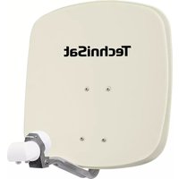
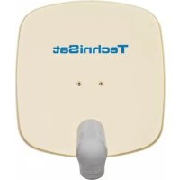
| Brand | TechniSat |
| Model | Viotenne 55 |
| Product type | Satellite antenna |
| Dish diameter | 55 cm |
| Target satellite | ASTRA 19.2°E |
| LNB type | Universal LNB compatible with ASTRA |
| Adjustable elevation angle | Yes, via adjustable inclined prism with scale |
| Adjustable azimuth angle | Yes, manual rotation |
| Mounting | On mast (diameter 42 mm) or wall mount |
| Kit contents | Dish, dish bracket, LNB arm, LNB holder, inclined prism, screws, retaining clip, manual |
| LNB power supply | Via the satellite receiver (coaxial cable 13/18 V) |
| Connectors | F connector |
| Maintenance | Clean with a soft, dry cloth. Do not use solvents. |
| Safety | Follow VDE 0855 standards. Disconnect before installing F connectors. |
| Certifications | CE |
Frequently Asked Questions - Viotenne 55 TECHNISAT
User questions about Viotenne 55 TECHNISAT
0 question about this device. Answer the ones you know or ask your own.
Ask a new question about this device
Download the instructions for your Satellite antenna in PDF format for free! Find your manual Viotenne 55 - TECHNISAT and take your electronic device back in hand. On this page are published all the documents necessary for the use of your device. Viotenne 55 by TECHNISAT.
USER MANUAL Viotenne 55 TECHNISAT
Installation instructions
1. Installing the outside unit
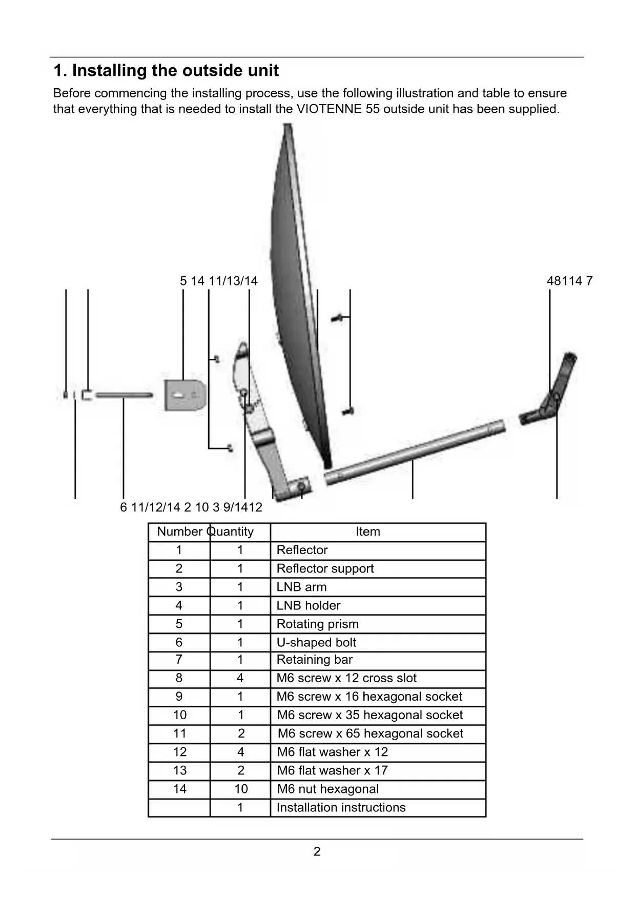
Before commencing the installing process, use the following illustration and table to ensure that everything that is needed to install the VIOTENNE 55 outside unit has been supplied.
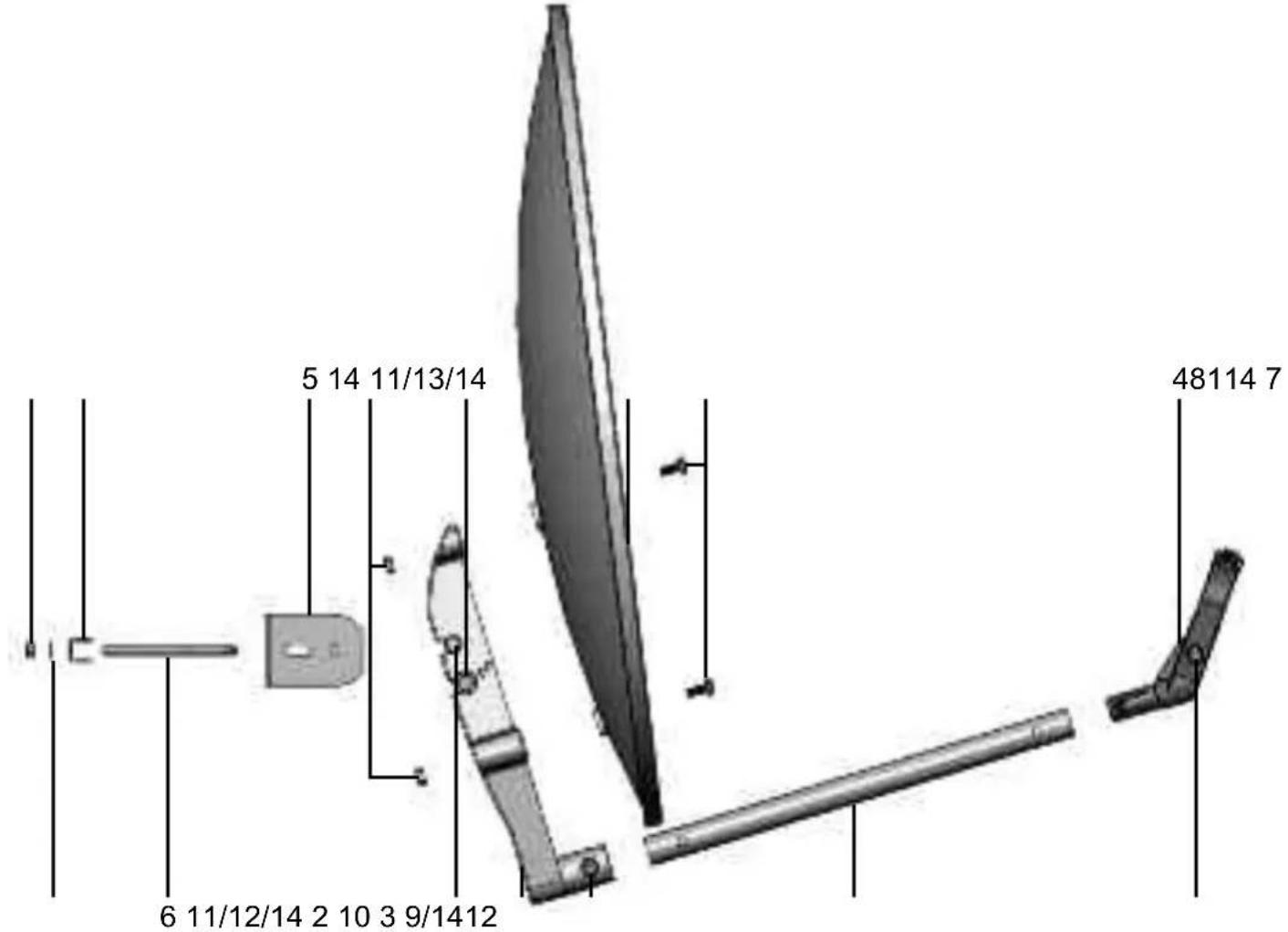
| Number | Quantity | Item |
| 1 | 1 | Reflector |
| 2 | 1 | Reflector support |
| 3 | 1 | LNB arm |
| 4 | 1 | LNB holder |
| 5 | 1 | Rotating prism |
| 6 | 1 | U-shaped bolt |
| 7 | 1 | Retaining bar |
| 8 | 4 | M6 screw x 12 cross slot |
| 9 | 1 | M6 screw x 16 hexagonal socket |
| 10 | 1 | M6 screw x 35 hexagonal socket |
| 11 | 2 | M6 screw x 65 hexagonal socket |
| 12 | 4 | M6 flat washer x 12 |
| 13 | 2 | M6 flat washer x 17 |
| 14 | 10 | M6 nut hexagonal |
| 1 | Installation instructions |
To install the outside unit proceed as follows:
Install the retaining bracket on the rotating prism
Insert screw 6 through the slot in the rotating prism 5 so that the thread points away from the rotating prism.
Insert retaining bar 7 into screw 6 as shown in the illustration.
In each case insert one flat washer 12 onto the two threaded ends of the screw 6 and screw on a nut 14, turning it several times.
Install the rotating prism on the reflector support
Insert the rotating prism 5 onto reflector support 2 so that the hole in the rotating prism 5 and the top hole in the reflector support 2 are positioned on top of each other.
Insert a screw 11 through a flat washer 12 and into the hole of the rotating prism 5.
On the other side, place a flat washer 12 onto the screw 11, put a nut 14 onto the threads and hand tighten.
Turn the rotating prism 5 so that its lower corner is pointing at the elevation angle EL, corresponding to your location.
Insert a second screw 11 through the flat washer 13 and into the hole in the reflector support 2 beneath the rotating prism 5.
On the other side, place a flat washer 13 onto the screw 11, put a nut 14 onto the threads and gently tighten.
Install the swivelling prism on the reflector support
Hold the reflector 1 in front of reflector support 2, as shown in the illustration.
Insert one nut 14 into each of the holes provided on reflector support 2.
Now connect up the reflector 1 and reflector support 2 to each other using the 4 screws 8.
Fitting the LNB arm onto the reflector support
Insert LNB arm 3 into the opening on the front of reflector support 2 and push it in fully, so that it is free of play as it sits in the opening.
If necessary, tap LNB arm 3 gently from the front. If you do so, please ensure that you do not bend LNB arm 3.
Insert screw 10 through the hole and screw it into a nut 14.
Fitting the LNB onto the LNB arm
Separate the two parts of the LNB holder 4 from each other and remove the two connecting bond bridges.
Hook the two parts of LNB holder 4 up to each other on the top side.
Place the LNB into the opening of LNB holder 4 (the LNB connections must be pointing downwards at the back) and fold them together.
Insert a nut 14 into the LNB holder and screw these together using screw 9.
Now insert LNB holder 4 onto LNB arm 3 and ensure that the former hooks into LNB arm 3.
2. Setting-up
Selecting the location
Make sure that there is a clear view towards the south from the chosen installation location for receiving ASTRA 19^ East.
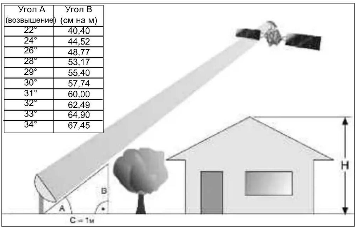
You can use the graphic shown below to see whether you have allowed for being far enough away from any nearby obstruction in order to avoid adversely affecting reception due to this obstruction.
Take care to ensure that the reflector is not overshadowed by an overhanging roof when installed on a terrace or balcony.
| Angle A (Elevation) | Incline B (cm per m) |
| 22° | 40,40 |
| 24° | 44,52 |
| 26° | 48,77 |
| 28° | 53,17 |
| 29° | 55,40 |
| 30° | 57,74 |
| 31° | 60,00 |
| 32° | 62,49 |
| 33° | 64,90 |
| 34° | 67,45 |
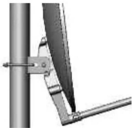
The outside unit should be assembled on a special vertical mast (diameter 42mm) or a wall mounted holder.

3. Safety instructions
Take care to ensure that the applicable European standards and VDE rules for guaranteeing electrical safety (e.g. VDE 0855, Part 1) are observed when installing.
Ask your specialist supplier about this if necessary.
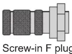
4. Fitting the F plug
Warning!
Only fit the F plug when the receiver is switched off!
When fitting the F plug, ensure that it is correctly fitted so as to avoid any operational faults or even the destruction of the Sat-receiver.
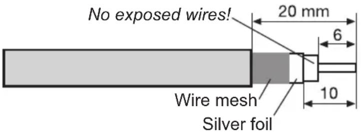
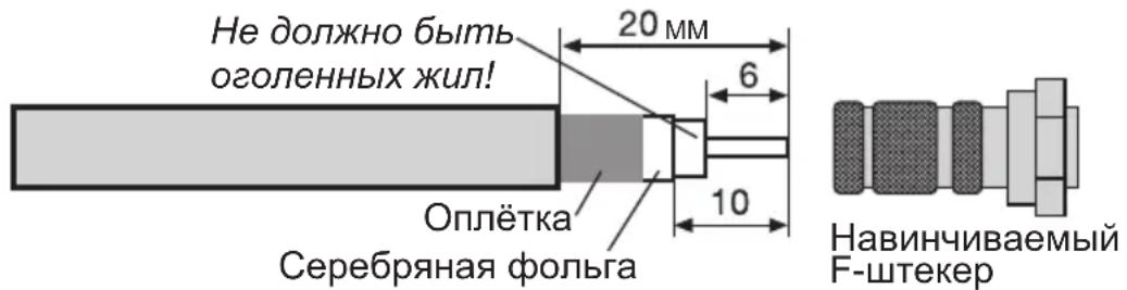
Remove 6mm of insulation from the end of the wiring using a sharp knife as far as the internal lead. When doing this, ensure that the internal lead is not damaged.
Remove the remaining wiring from the surrounding flex.
Now remove 10mm of the outer plastic sleeve until the sheathing flex is opened up without being damaged.
Ensure that none of the wiring from the surrounding flex is touching the internal lead.
Now turn the F plug carefully on the cable until the inner lead end is flush with the front edge of the F plug
Finally check once again that none of the wire from the surrounding flex is touching the internal cable lead. The F plug is now correctly installed.
Observe the appropriate assembly method by using Crimp F plugs and follow the manufacturer's instructions.
5. Aligning the outside unit
The outside unit should be aligned using a measuring device.
It can also be carried out using a sat-finder.
Should neither of these be available, the unit can be aligned using a receiver and a television set.
-
Connect the LNB and the receiver via a suitable coaxial cable.
-
Close the receiver and the TV set and set the receiver to a programme setting on which a satellite programme can be received (e.g. ARD for ASTRA).
-
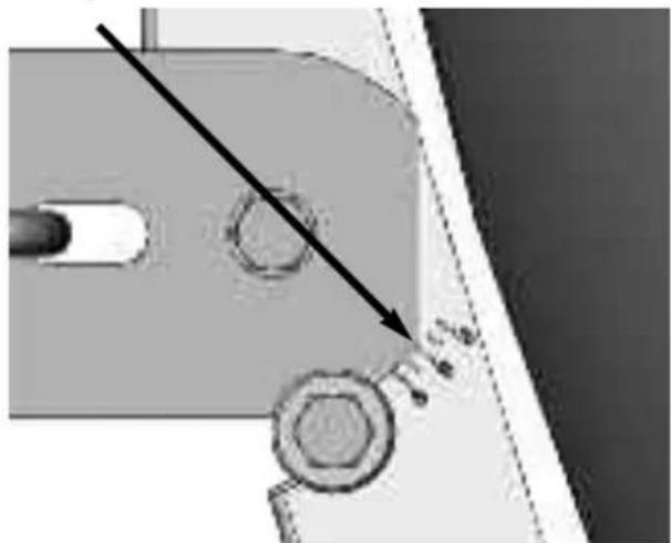
Now set the angle that corresponds to your location, using the imprinted scale and lock the reflector (the reference point on the graduated scale is the lower corner of the rotating prism).
-
Now turn the reflector slowly in an eastwards or westwards direction (azimuth angle) until you receive the TV picture for the setting.
- The reflector still needs to be fine-tuned. To do this, it is a good idea to call up the receiver status display (with the signal level and quality). Check the receiver instruction book when doing so.
- Now carefully change the azimuth (east/west) and angle of elevation in such a way that the signal level and signal quality show the highest possible amplitude level.
- Now tighten all the screws and make sure that reception has not been adversely affected when you have done this. The reflector is now fully assembled and optimally adjusted to the desired satellite.
Your product has the CE mark and meets all the requisite EU standards.
Subject to change for amendments and printing errors. Version 10/04
Duplication and reproduction only with the publisher's approval.
VIOTENNE is a registered trademark of
Viola Digital GmbH
Nordstrasse 4
39418 Stassfurt
Germany


VIOTENNE 55
Notice de montage
YcTaHObKa 3epKaJa Ha DepeKaTeJe
YcTaHOBnTb 3epKaJIo 1 nepeI depKaTeJIeM 2, KaK n3o6paXKeHo Ha pncyHke.
YcTaHOBntb no OndHou raKe 14 B COOTBeTCTByIOUne OTBepCTnA depKaTeIa 2.
Припомоши четырж ВИNTOB 8 пикpyтntь зеркало 1 кдерхаTeNo 2.
YcTaHOBka WtAHrM MUsE Ha DepeKaTeJIe 3epKaJa
BCTaBnTb wTaHry MUsE 3 B OTBePcTne ČepKaTeJRA 2, pacNoIoxKeHHoe cpeDn, n nepemecITb ee do ynpa, yTo6bl OHa 3aTeM ceJa B OTBePcTne 6e3 3a3Opa. ДЯЗТOrO HEmHoro noctyauTb cpeDn no wTaHre MUsE 3. CJeInte 3a Tem, yTo6bl He nOrHyTB wTaHry MUsE 3.
YCTaHOBntb BnHT 10 B OTBepCTne N BBnHTNTb eRo B raKy 14.
YctaHObKa MUsHa waTaHre
Pa3beHnHTb o6e yactn nepkaTeIaMUSB 4 n ydaJIITb nepeMbIyKn.
3aΦnKcnpoBaTb Cbepxoyobe yactn depkaTeJ MUsE 4 OndaB pyroJ.
YctaHOBtB MUS B OTBepCTne DepeKaTeIe 4 (pa3bEMbl MUsb DOJXHbI yka3bIBaTb Ha 3aNDIO CTOPOHy BHN3) IN CNOKHTb DepeKaTeIb.
YctaHOBntb raiky 14 B depkataIb Ml6 n 3akpenIb erO BVHTOM 9.
YcTaHOBnTB DepeXaTeIb MUsE 4 B Wtahry MUsE 3 n 3aФнксрOBaTb B Hei.
2. YctaHOBka
BbI6op MecTa yCTaHOBKn
Heo6xOIMO y6eINTbc8, YTO B MeCTe yCTaHOBKn aHTeHHbl oBeCneueHa CBO6Oda 630paB IOXHOM HnnpaBnEHnn dIy npEema CNrHana OT cnyTHnka ASTRA B NOJoxeHN 19° BOCT. DOJROtbl. Pn nOMOu nnPnBEdeHHoro HIXe PNcYHka MOXHO ONpeDeJIITb, Ha DOCTaTOUHOM JIpacCToRHN HaxoDNTc8 6JIHXaJWee npenTCTBne, YTObI N36ExKaTb NOMex dIy npEema CNrHana, OBCNOBNEHHbIX HAJIuHnEM 3TOr OpeNATCTBnra. Pn yCTaHOBKe aHTeHHbl Ha Teppace IIN 6aJIkoHe o6paTntb BHIMaHHe Ha To, YTO6bl3epKaIO aHTeHHbl He 3aTeHnIOocb BbICTyNaIOUeKpbIwei.
Hapyxhbl 6nok yctaHaBnBaIoT Ha cneuaJIbHOB BepTKKaIbHOJ onope (dnaMeTp 42 MM) IIN KpeIaT Ha cTeHe pN NOMOUs KPOHSTeHHa.
3. Texнka 6e3oNaChocTn
C ceIbIO oBecneueHnra 3JeKtpnuecko 6e3OanachocTn npu yCTaHOBke aHTeHHbI Heo6XoIMo co6IIOdaTb COOTBeTCTByUOuIne eBponeNCKne cTaHapTbI n HopMbVDE (Co103a Hemeuzx 3JeKtpNKOB) (HaNPmep, VDE 0855, Yac7b 1). Pn Hoe6XoIMOCtN 3a KOHCyIbTaucne MoXHo O6paTnTBcR K npOaBu.
4. YctaHOBka F-Tekepa
BHHMaHHe!
YcTaHOBky F-Tekepa npOn3BODnTb TOnbKO B o6ecToeHHOM COCTOHN npHEmHOy YcTaHOBKn!
YcTaHOBky F-шТeКepa BbINOJIHЯTb C OCo60I TuaTeJIbHOCtBu, YTO6bl NCKJIIOUHTb HeICnPaBHOCTN IJINДaJKe NOBpeKdEHNe peCnBepa B pe3yIbTaTe HeIpaBnIbHOJ yCTaHOBKn ShTeKepa.
При поMuи OCTporo HOxa ydaIHTb 6 MM n3OJaun C Ka6eJIbHbIX KOHcOB Ha rny6nHy BHyTpEHHero npOBd. При 3TOM He NOBpeiNTb BHyTpEHHn npOBOD.
YdaNTb BbICtynaIOUyIO ONNeTky 3KpaHa.YdaNTb 10 MM BHeUHei o6oNoCKn Ka6eJr DO 3KpaHpyUOSeI ONNeTKn, He NOBpeDnB ee.
Y6eIITbc8, YTO ONIETKa He KacaetcBHyTpeHHeRo npOBOda.
Octopojxno HabepHyb F-Tekep Ha Ka6eIb TaK, YTO6bl BHyTpEHHn npOBo3aKaHcHbA1ncs 3aNoDnIcuO c nepeDnM Kpaem F-Tekepa.
3aTeM eue pa3 npOBepuTb, yTo6bl OJIeTKa He Kacanacb BHyTpHHeRo npOBoHa Ka6eIa. Tenepb F-WeKepe npaBnIbHO CMOHTnpoBaH.
Ito ukeane yctaHOBntb yroI, COOTBeTCTByuOni BaWemy MeCy, n 3aФNKcnpoBaTb 3epkaNo (ToUKo OTCeTa rpaDyCHO uKaJIbI YBnReTcHxHn yroI NOBOPOTHO npN3Mb).

5. OpnieHTnpOBaHne HapyxHoro 6Ioka
Bo3MOXHbI n3MeHeHn, He nCKJIIOueHbI oneaTKn. No coCToHnO ha 10/04
KoHnPOBaHHe N TnpaxnIOBaHHe DOnyckaetc ToIbko C pa3peWeHHa 3daTeJIa.
VIOTENNE YBJIaTc3apeHCTpnpoBaHHbIM TOBapHbIM 3HaKOM KOMnAHm
Viola Digital GmbH

- Installing the outside unit
- Install the retaining bracket on the rotating prism
- Install the rotating prism on the reflector support
- Install the swivelling prism on the reflector support
- Fitting the LNB arm onto the reflector support
- Fitting the LNB onto the LNB arm
- Setting-up
- Selecting the location
- Safety instructions
- Fitting the F plug
- Warning!
- Only fit the F plug when the receiver is switched off!
- Aligning the outside unit
- VIOTENNE 55
- Notice de montage
- YcTaHObKa 3epKaJa Ha DepeKaTeJe
- YcTaHOBka WtAHrM MUsE Ha DepeKaTeJIe 3epKaJa
- YctaHObKa MUsHa waTaHre
- YctaHOBka
- BbI6op MecTa yCTaHOBKn
- Texнka 6e3oNaChocTn
- YctaHOBka F-Tekepa
- BHHMaHHe!
- YcTaHOBky F-Tekepa npOn3BODnTb TOnbKO B o6ecToeHHOM COCTOHN npHEmHOy YcTaHOBKn!
- OpnieHTnpOBaHne HapyxHoro 6Ioka
Brand : TECHNISAT
Model : Viotenne 55
Category : Satellite antenna