
KHS 3700 - Log splitter AL-KO - Free user manual and instructions
Find the device manual for free KHS 3700 AL-KO in PDF.
| Product type | Log splitter |
| Brand | AL-KO |
| Model | KHS 3700 |
| Rated voltage | 230 V / 50 Hz |
| Minimum connection cable cross-section | 2.5 mm² |
| Minimum mains fuse | 16 A |
| Measured sound power level | 86 dB(A) |
| Guaranteed sound power level | 88 dB(A) |
| Recommended hydraulic oil | Viscosity class HLP 46 |
| Intended use | Private use, garden or home, splitting cut wood |
| Safety device | Motor safety switch (overload protection) |
| Maximum cable length | 10 m |
| Recommended cable type | Rubber cable H07RN-F (VDE 0282 part 14 standard) |
| Routine maintenance | Cleaning guide cylinders, sharpening splitting wedge, checking oil level |
| Spare parts | Use only original parts |
| Warranty | Legal period according to country of purchase |
Frequently Asked Questions - KHS 3700 AL-KO
User questions about KHS 3700 AL-KO
0 question about this device. Answer the ones you know or ask your own.
Ask a new question about this device
Download the instructions for your Log splitter in PDF format for free! Find your manual KHS 3700 - AL-KO and take your electronic device back in hand. On this page are published all the documents necessary for the use of your device. KHS 3700 by AL-KO.
USER MANUAL KHS 3700 AL-KO
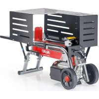
natural_image
Two identical robotic dog-like devices with visible wheels and control panels, shown from different angles (no text or symbols)| D | GB |
| F | I |
| NL | E |
| H | PL |
| CZ | SK |
| RUS | S |
| FIN | DK |
| N | RO |
| SLO | HR |
INFORMATION | MANUALS | SERVICE
HOLZSPALTER
KHS 3700 / 5200
Betriebsanleitung


© Copyright 2010
AL-KO KOBER GROUP Kötz, Germany
This documentation or excerpts therefrom may not be reproduced or disclosed to third parties without the express permission of the AL-KO KOBER GROUP.

natural_image
Close-up of a mechanical component with a pinwheel and circular arrow indicator (no readable text or symbols)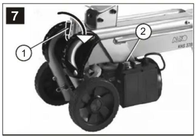
natural_image
Illustration of a funnel pouring liquid into a container with a bottle, next to a conical container (no text or symbols)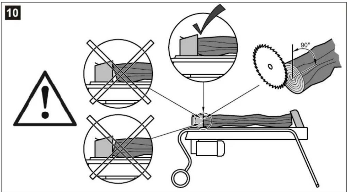
 | ||
| TypArt. Nr. | KHS 3700112 425 | KHS 5200112 426 |
 | 230 V AC / 50 HZ 230 V AC / 50 Hz | |
 | 1500 W 2200 W S6 40% | |
 | max. 4,0 t max. 5 t | |
 | max. 250 mm max. 250 mm | |
 | max. 370 mm max. 520 mm | |
 | 16 MPa (160 bar) 20 MPa (200 bar) | |
 | 2,7 l 3,1 l | |
 | II / IP 54 II / IP 54 | |
 | 42 kg 48 kg | |
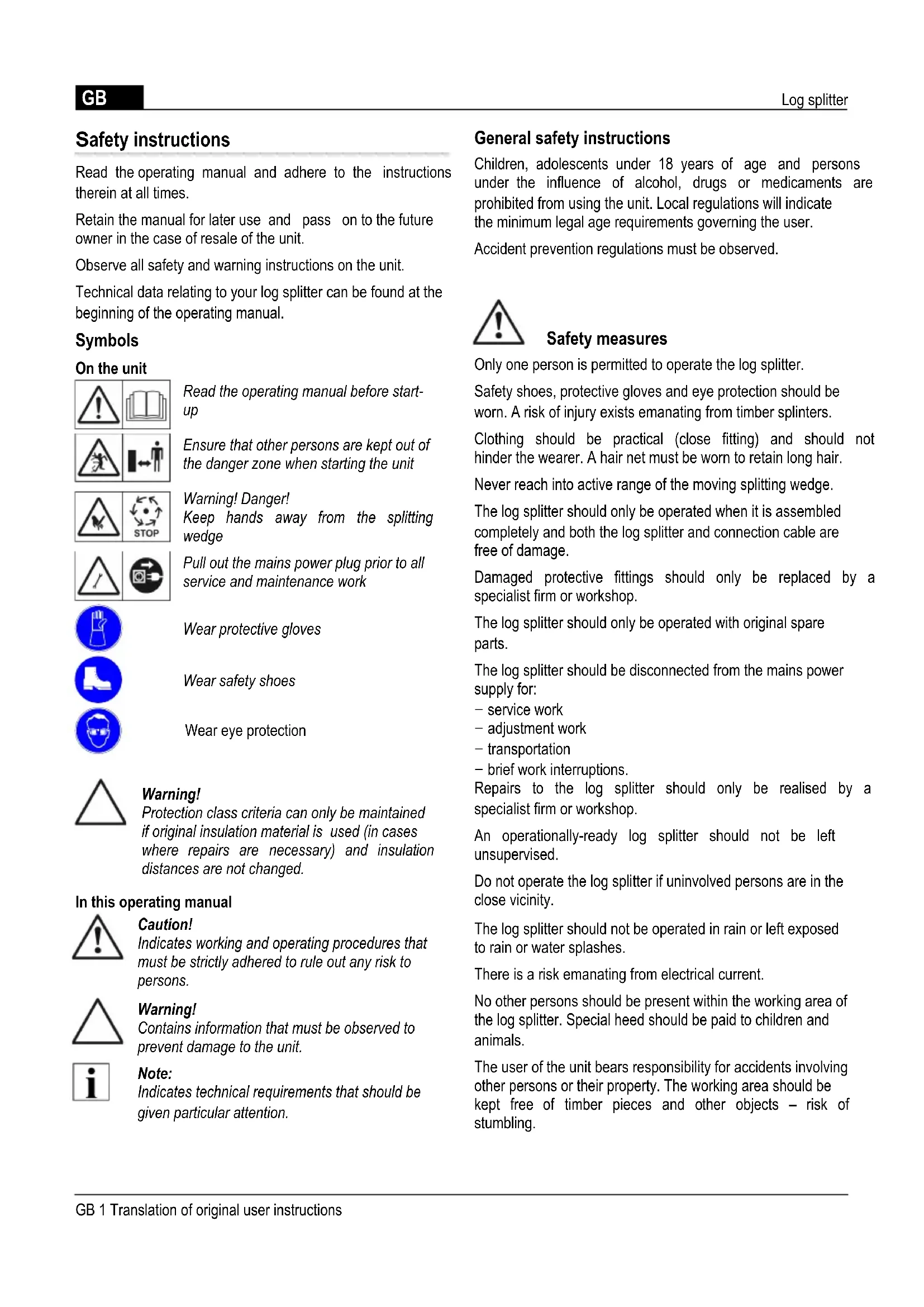
Sicherheitshinweise
Read the operating manual and adhere to the instructions therein at all times.
Retain the manual for later use and pass on to the future owner in the case of resale of the unit.
Observe all safety and warning instructions on the unit.
Technical data relating to your log splitter can be found at the beginning of the operating manual.
Symbols
On the unit

Read the operating manual before start-up
Ensure that other persons are kept out of the danger zone when starting the unit
Warning! Danger!
Keep hands away from the splitting wedge
Pull out the mains power plug prior to all service and maintenance work

Wear protective gloves

Wear safety shoes

Wear eye protection

Warning!
Protection class criteria can only be maintained if original insulation material is used (in cases where repairs are necessary) and insulation distances are not changed.
In this operating manual

Caution!
Indicates working and operating procedures that must be strictly adhered to rule out any risk to persons.

Warning!
Contains information that must be observed to prevent damage to the unit.

Note:
Indicates technical requirements that should be given particular attention.
General safety instructions
Children, adolescents under 18 years of age and persons under the influence of alcohol, drugs or medicaments are prohibited from using the unit. Local regulations will indicate the minimum legal age requirements governing the user.
Accident prevention regulations must be observed.

Safety measures
Only one person is permitted to operate the log splitter.
Safety shoes, protective gloves and eye protection should be worn. A risk of injury exists emanating from timber splinters.
Clothing should be practical (close fitting) and should not hinder the wearer. A hair net must be worn to retain long hair.
Never reach into active range of the moving splitting wedge.
The log splitter should only be operated when it is assembled completely and both the log splitter and connection cable are free of damage.
Damaged protective fittings should only be replaced by a specialist firm or workshop.
The log splitter should only be operated with original spare parts.
The log splitter should be disconnected from the mains power supply for:
- service work
- adjustment work
- transportation
– brief work interruptions.
Repairs to the log splitter should only be realised by a specialist firm or workshop.
An operationally-ready log splitter should not be left unsupervised.
Do not operate the log splitter if uninvolved persons are in the close vicinity.
The log splitter should not be operated in rain or left exposed to rain or water splashes.
There is a risk emanating from electrical current.
No other persons should be present within the working area of the log splitter. Special heed should be paid to children and animals.
The user of the unit bears responsibility for accidents involving other persons or their property. The working area should be kept free of timber pieces and other objects – risk of stumbling.
Safety equipment
Motor circuit breaker
The motor circuit breaker switches the motor off in the event of overloading of the log splitter. The motor circuit breaker function should not be deactivated.
Proceed as follows if the motor circuit breaker deactivates the log splitter:
- Disconnect the log splitter from the mains power supply.
- Remedy the cause of overloading.
- Re-establish the power connection after allowing the unit to cool for several minutes and switch on the log splitter.
Connection cable
Only rubber cable complying with the H07RN-F quality standard stipulated in VDE 0282 Part 14 with a wire cross section of min. 2.5 mm ^2 should be used.
The max. permissible cable length is 10 m. A longer cable impairs the motor performance and, consequently, the function of the log splitter.
The connection cable, plug and connection socket should be free of damage.
Repairs to the connection cable, plug and connection socket should only be realised by a specialist electrical firm workshop. A defective connection cable (e.g. with cracks, cuts or bends in the insulation) should not be used.
Plug connections should not be exposed to damp or water.

Caution!
Do not damage or sever the connection cable.
Proceed as follows in case of damage:
- Disconnect the connection cable immediately from the mains power supply.
Electrical requirements:
KHS 3700, KHS 5200 models
- AC 230 V / 50 Hz
- Min. connection cable cross section = 2.5 mm ^2
- Min. mains connection fuse protection = 16 A
Correct use
The log splitter is designed for private use in the home and garden.
The log splitter is designed exclusively for the following applications:
- Splitting freshly-cut timber that does not exceed the dimensions specified in the technical data.
Incorrect use
- Splitting of timber containing metal components such as nails, wire, metal braces, etc. is prohibited
- Operation in potentially-explosive atmospheres is not permitted
– Any other utilisation above or beyond correct use is prohibited.
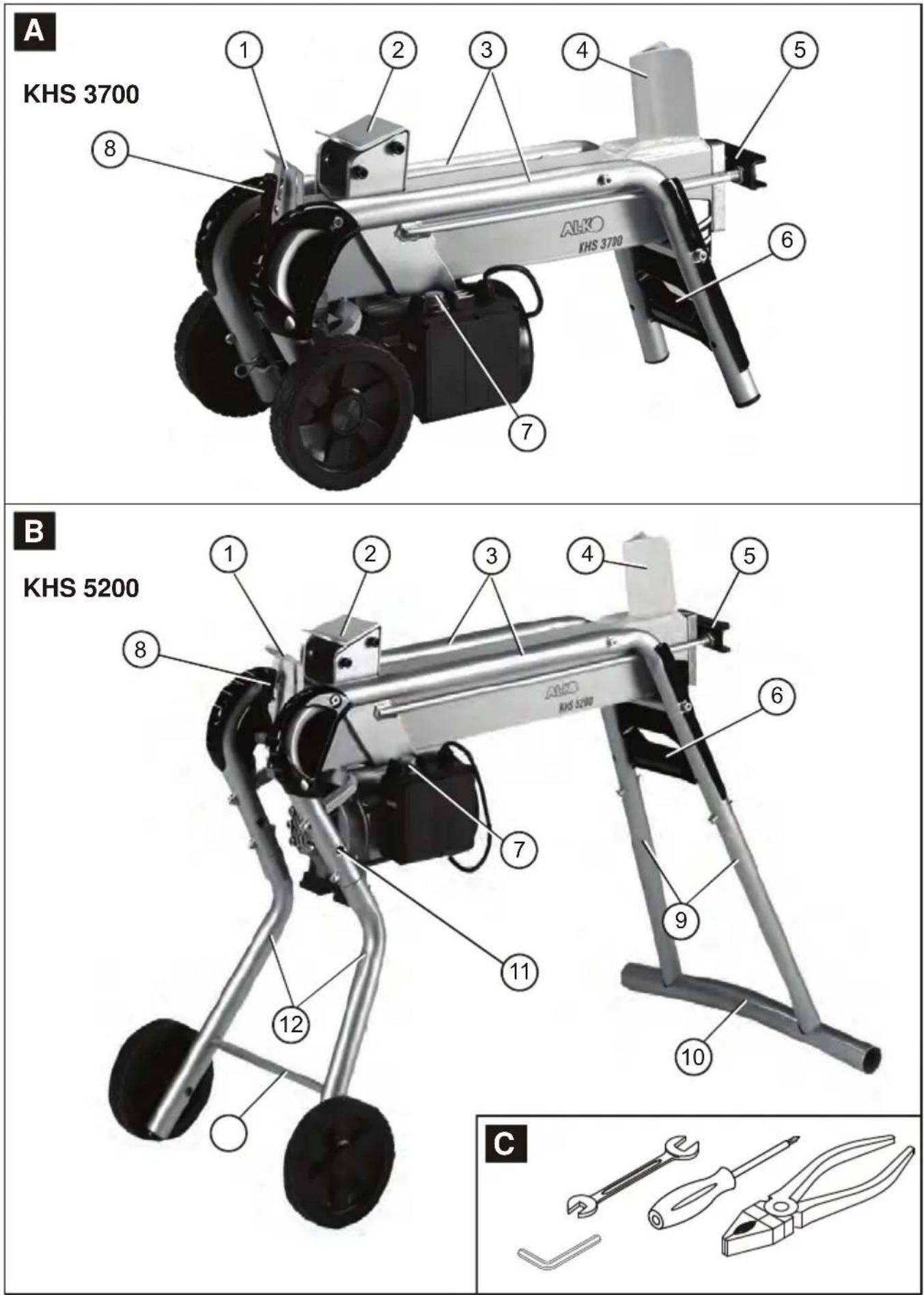
Unit description (Illus. A/B)
or 1 Protection cover
2 Log pusher
3 Log guide tubes
4 Splitting wedge
5 Piston rod
6 Transportation bracket
7 ON/OFF switch on electric motor
8 Operating lever
9 Rear feet (only KHS 5200)
10 Support foot (only KHS 5200)
11 Park position transport wheels (only KHS 5200)
12 Front feet (only KHS 5200)
13 Front cross member (only KHS 5200)
Unpacking/Assembly

Caution!
The log splitter should only be used when all its component parts have been completely assembled.
- Check the package contents (Illus. A/B). Inform the dealer if deficiencies are detected.

Note:
Tools required for assembly/operation are depicted in Illus. C. These are not included in the scope of delivery.
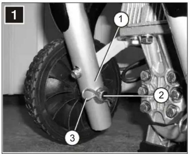
Mounting the transport wheels
- Fit the axle (Illus. 1-2) from outside through the wheel and through the tube (Illus. 1-1) and secure it with the spring plug (Illus. 1-3).
Mounting the feet (KHS 5200)
- Mount the transportation wheels on both the front feet; see Section "Mounting the transport wheels."

Warning!
The transportation wheels are only used to transport the log splitter. During splitting operation, the wheels must be removed from the feet and mounted in the park position (Illus. B-11).
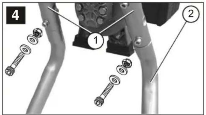
- Tilt the log splitter on to one side and mount the front and rear foot.
- Fit the foot (Illus. 2-2 and Illus. 4-2) up to the stop limit inside the tubular frame (Illus. 2-1 and 4-1) and secure it firmly in position with screws, washers, and locking nuts.
- Tilt the log splitter onto the opposite side with the help of a second person, and mount the other feet and afterwards put it upright.
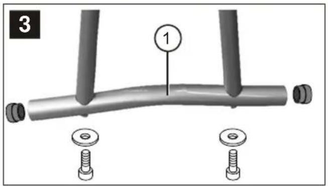
- Put the log splitter in vertical position (piston rod upright) and screw the support foot (illus. 3-1) on the rear feet.
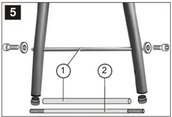
- Erect the log splitter and mount the cross members in front (Illus 5-1) with the help of the threaded rod (Illus. 5-1).
Mains connection
- Connect the cable to the mains supply.
Operation

Caution!
The log splitter should not be operated if components (e.g. the protective hoops) are missing or defective or the connection cable is damaged.
Prior to every use
- Conduct a visual inspection of the log splitter.
- The log splitter should not be operated if components are missing, defective or loose.
- Visually inspect the connection cable. A defective connection cable (e.g. with cracks, cuts, crushing damage or bends in the insulation) should not be used.
- Visually inspect the hydraulic components for leaks.
Log splitter start-up

Caution!
The log splitter should only be used by one person.
- Position the log splitter horizontally on a level, firm surface, better with a slight inclination towards the operating lever (since the valves are seated here). If inclined towards the splitting wedge it loses splitting force. Do not deposit the log splitter on the connection cable!
- Lay the connection cable so that it cannot be damaged by bending, crushing or otherwise.

Warning!
The transportation wheels with model KHS 5200 are only used to transport the log splitter. During splitting operation, the wheels must be removed from the feet and mounted in the park position.
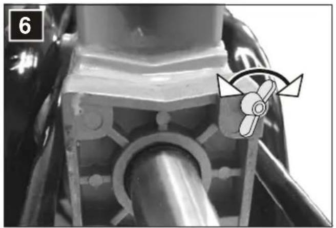
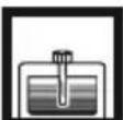
- Loosen the venting screw (Illus. 6) by 3-4 turns.

Note:
After splitting, tighten the venting screw (Illus. 6) again.
- Depending on the length, lay the log such that the wooden log is held by the log guide tubes.

Warning!
Never lay the log on the splitter in transverse direction, see Illus. 10.
Never force the splitting of a log by sustaining the hydraulic pressure over several seconds.
Operation
- With one hand, press the green switch on button of the electric motor (Illus. 7-2) and hold it pressed.
- After the motor has attained its end speed, press the operating lever with the other hand (Illus. 7-1) fully downwards. The log pusher will press the log against the splitting wedge. The log will be split.
- By releasing the green switch-on button or the operating lever, the log pusher moves back into its end position.
Transportation

Caution!
Pull out the unit plug and tighten the vent screw prior to every change of location.

Warning!
Do not transport the log splitter on the cylinder fastening.
- Hold the log splitter on the transport bracket to transport it.
Maintenance and care

Caution!
Switch off the log splitter and disconnect from the mains power supply prior to each working operation with the log splitter. Repairs to the log splitter should only be realised by a specialist firm or workshop.
Caring for the log splitter
Cleaning the guide rail
- Clean the guide rail of the log pusher regularly, especially when splitting wood that is rich in resin.
Maintenance work
Sharpening the splitting wedge
- The splitting wedge should be sharpened with a suitable file if necessary.
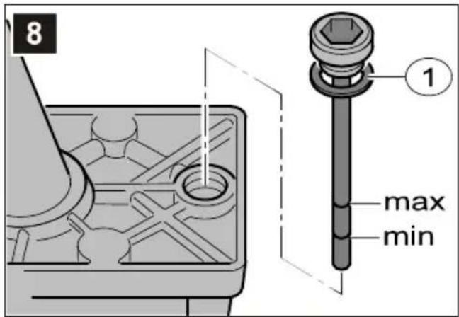
Checking the hydraulic oil filling level

Note:
Always check the hydraulic oil level when the log pusher is moved inwards. The log splitter should be in a vertical position.

Caution!
To erect and hold the log splitter a second person is required.
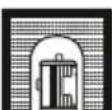
- Unscrew and remove the oil inspection rod (Illus. 8) and wipe with a clean, lint-free cloth.
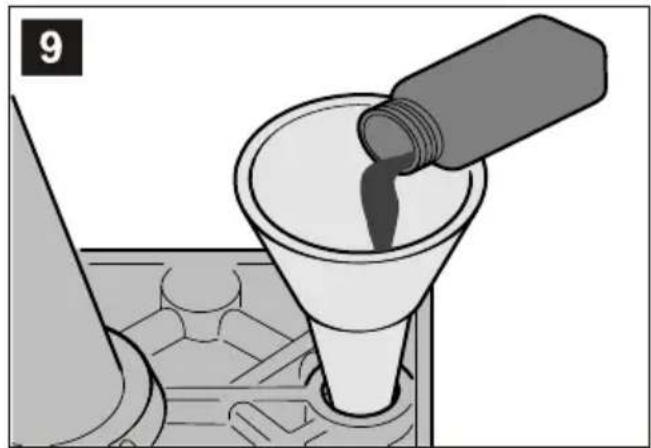
- Insert the oil inspection rod (do not screw it in) and pull out again. The oil level should be between the markings "min" and "max" (see Illus. 8). Top up the hydraulic oil if necessary (see Illus. 9).
- Check the seal (Illus. 8-1) for damage and replace if necessary.
- Screw in the oil inspection rod and tighten it slightly, in order to avoid damage to the threads of the cylinder head.

Warning!
Refill only with viscosity class HLP 46 hydraulic oil.
An oil change is not necessary.
Malfunctions
Switch off the log splitter and pull out the mains power plug in the event of malfunctions occurring. Engage a specialist firm or workshop to remedy malfunctions that cannot be rectified on the basis of the following table.
| Malfunction Cause Remedy | ||
| The log pusher does not move out/in | Too little hydraulic oil Top up hydraulic oil | |
| Hydraulic pump is defective Replace hydraulic pump | ||
| The splitter is inclined towards the splitting wedge | Position the splitter on a horizontal plane or inclined towards the operating lever | |
| The log pusher does not exert any force | Too little hydraulic oil Top up hydraulic oil | |
| The splitter is inclined towards the splitting wedge | Position the splitter on a horizontal plane or inclined towards the operating lever | |
| Hydraulic pump makes a whistling noise, the log pusher moves with a jerking motion | Too little hydraulic oil Top up hydraulic oil | |
| The splitter is inclined towards the splitting wedge | Position the splitter on a horizontal plane or inclined towards the operating lever | |
| Air inside the circulation system Open the venting screw | ||
| Motor becomes excessively hot Cable cross section is too small Use cable with larger cross section | ||
| Motor is not starting | Thermostatic switch has switched off | Wait until the motor has cooled down |
| Mains plug or socket is defective | Let an electrician check the plug | |
| Cable is defective | Replace by an electrician | |
| Electric motor is defective | Let an electrician check the motor | |
Environmental protection, disposal

Do not dispose of old units in household waste!
The packaging, unit and accessories are made of materials that can be recycled and should be disposed of in a suitable manner.
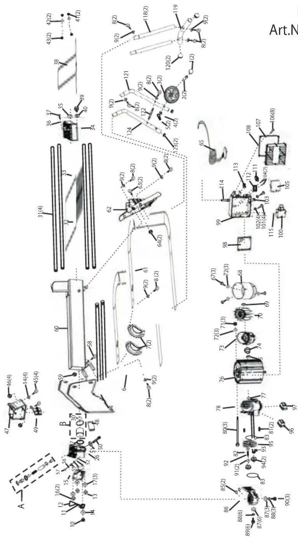
KHS 3700
Art.Nr. 112425
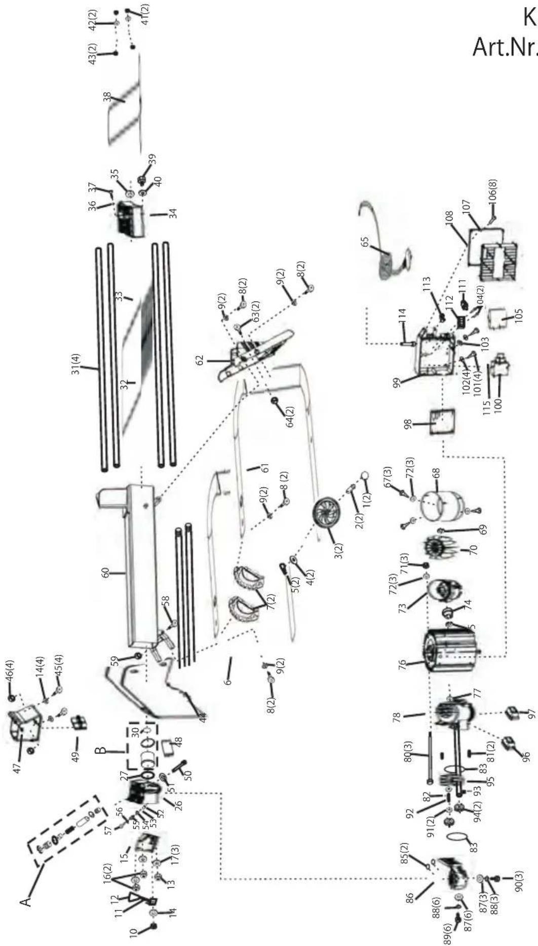
| Pos. | Art.Nr. | Bezeichnung |
| 82 | 463607 | STAHLKUGEL 2,5MM |
| 83 | 463608 | O-RING 46,2 X 1,8 |
| 85 | 463610 | O-RING 10,6 X 2,65 |
| 86 | 463611 | GEHÄUSE ZAHNRADPUMPE |
| 87 | 463612 | FLACHSCHEIBE 8 |
| 88 | 463613 | FEDERSCHEIBE 8 |
| 89 | 463614 | SECHSKANTBOLZEN M8X55 |
| 90 | 463615 | SECHSKANTBOLZEN M8X30 |
| 91 | 463616 | SICHERUNGSRING |
| 92 | 463617 | BOLZEN ZAHNRAD |
| 93 | 463618 | PIN 2,5 X 4 |
| 94 | 463619 | ZAHNRAD |
| 95 | 463620 | ZAHNRADGEHÄUSEBLECH |
| 96 | 463621 | STOPFEN LINKS |
| 97 | 463622 | STOPFEN RECHTS |
| 98 | 463623 | DICHTUNG |
| 99 | 463624 | KLEMMKASTEN MOTOR |
| 100 | 463625 | SCHALTER |
| 101 | 463626 | SCHRAUBE M4 X 12 |
| 102 | 463627 | SCHEIBE 4 |
| 103 | 463628 | ZAHNSCHEIBE 4 |
| 104 | 463629 | SCHRAUBE M3 X 16 |
| 105 | 463630 | KONDENSATOR |
| 106 | 463631 | BLECHSCHRAUBE 2,9 X 12 |
| 107 | 463632 | KLEMMKASTENDECKEL |
| 108 | 463633 | DICHTUNG |
| 111 | 463634 | ÜBERLASTSCHALTER KPL. |
| 112 | 463635 | MOTORANSCHLUßLEISTE |
| 113 | 463636 | KABELZUGENTLASTUNG |
| 114 | 463637 | KABELVERSCHRAUBUNG KPL. |
| 115 | 411424 | ÜBERWURFMUTTER SCHALTER |
| A | 463645 | HYDRAULIKVENTILSATZ |
| B | 463646 | KOLBENRINGSATZ |
| Po s. | Art.Nr. | B ezeic hnung |
| 46 | 700122 | MUTTER |
| 47 | 463573 | STAMMSCHIEBER |
| 48 | 463574 | KUNSTSTOFFEINSATZ UNTEN |
| 49 | 463575 | KUNSTSTOFFEINSATZ OBEN |
| 50 | 463576 | BOLZEN |
| 51 | 463577 | AUSGLEICHSSCHEIBE |
| 52 | 463578 | BOLZEN |
| 53 | 463579 | STAHLKUGEL 6MM |
| 54 | 463580 | DRUCKEINSTELLFEDER |
| 55 | 463581 | MADENSCHRAUBE ISKT |
| 56 | 463582 | O-RING 5,5 X 2 |
| 57 | 463583 | BOLZEN M8H ISKT |
| 58 | 463584 | ISKT.- SCHRAUBE M8 X 35 |
| 59 | 463585 | MUTTER M 8 SBS |
| 60 | 411301 | SPALTTISCH |
| 61 | 411302 | ROHRAHMEN RECHTS |
| 62 | 463588 | ROHRABDECKUNG RECHTS |
| 63 | 463589 | ISKT.- SCHRAUBE M5 X 12 |
| 64 | 463590 | STELLMUTTER M8 |
| 65 | 463591 | KABEL MIT STECKER 230 V |
| 67 | 463592 | SCHRAUB M5 X 8 |
| 68 | 463593 | LÜFTERDECKEL |
| 69 | 463594 | SCHNELLSICHERUNG 17 |
| 70 | 463595 | LÜFTERFLÜGEL |
| 71 | 463596 | MUTTER M5 |
| 72 | 463597 | FEDERSCHEIBE 5 |
| 73 | 463598 | LAGERDECKEL HINTEN MOTOR |
| 74 | 463599 | KUGELLAGER |
| 75 | 463600 | SCHNELLSICHERUNG 42 |
| 76 | 463601 | MOTOR 230V |
| 77 | 463602 | SIMMERRING 11 X 26 X 7 |
| 78 | 463603 | LAGERDECKEL VORNE MOTOR |
| 79 | 463604 | FLACHSCHEIBE 5 |
| 80 | 463605 | SECHSKANTBOLZEN M8X185 |
| 81 | 463606 | PIN 7,8 X 24 |
| Po s. | Ar t Nr. | Be z e i ch nung |
| 1 | 463530 | RADKAPPE |
| 2 | 463531 | RADSCHRAUBE |
| 3 | 463532 | RAD |
| 4 | 463533 | SC HEIBE |
| 5 | 463534 | SICHERUNGSSTECKER |
| 6 | 411295 | ROHRAHMEN LINKS |
| 7 | 463536 | ROHRABDECKUNG |
| 8 | 463537 | ISKT SCHRAUBE M8X50 |
| 9 | 463538 | SC HEIBE GEWÖLBT |
| 10 | 463539 | FESTSTELLMUTTER |
| 11 | 463540 | BEDIENHEBEL |
| 12 | 463541 | KNOPF BEDIENHEBEL |
| 13 | 463542 | HUTMUTTER M10 |
| 14 | 463543 | SC HEIBE 10 |
| 15 | 463544 | GRUNDPLATTE |
| 16 | 463545 | MUTTER |
| 17 | 463546 | KUPFER DICHTUNG 10 MM |
| 26 | 463553 | ALUDECKEL HINTEN |
| 27 | 463554 | O-RING 55 X 3.1 |
| 30 | 463557 | O-RING 32 X 3.5 |
| 31 | 411296 | FÜHRUNGSSCHIENEN |
| 32 | 411297 | HYDRAULIKZYLINDER |
| 33 | 411298 | RÜCKHOLFEDER |
| 34 | 463561 | ALUDECKEL VORNE |
| 35 | 463562 | SIMMERRING |
| 36 | 463563 | O-RING, 7X1.9 |
| 37 | 463564 | FLÜGELSCHRAUBE 5 X 12 |
| 38 | 411299 | FÜHRUNGSWELLE |
| 39 | 463566 | ÖLMESSSTAB |
| 40 | 463567 | SC HEIBE |
| 41 | 463568 | SICHERUNGSMUTTER |
| 42 | 463569 | FEDERRING 14 |
| 43 | 463570 | MUTTER M 14 |
| 44 | 411300 | FÜHRUNGSTEIL KPL. |
| 45 | 463572 | ISKT.-SCHRAUBE M10 X 25 |
Antonio De Filippo, Managing Director
Garantie
EC declaration of conformity
We hereby declare that this product, in the form in which it is marketed, meets the requirements of the harmonised EU guidelines, EU safety standards, and the product-specific standards.
Product
Log splitter
Serial number
G4064065
Model
KHS 3700
KHS 5200
Sound power level
measured / guaranteed 86 / 88 dB(A)
Manufacturer
AL-KO Geräte GmbH
Ichenhauser Str. 14
89359 KOETZ
DEUTSCHLAND
EU directives
2006/42/EG (2009-12-29 ...)
2006/95/EG
2004/108/EG
2000/14/EG (13)
Conformity evaluation
2000 /14/EG
Appendix VI
Executive Officer
Anton Eberle
Ichenhauser Str. 14
89359 KOETZ
DEUTSCHLAND
Harmonised standards
EN 60335-1; VDE 0700-1:2007-02
EN 60204-1; VDE 0113-1:2007-06
EN 60204-1/A1; VDE 0113-1/A1:2008-01
EN 609-1:1999-05
EN 609-1/A1:2004-05
EN 609-1/A2:2008-04
Kötz, 2010-02-08

Antonio De Filippo, Managing Director
Warranty
If any material or manufacturing defects are found during the statutory customer protection period, we will either repair or replace the equipment, whichever we consider the more appropriate. This statutory period may vary according to the legislation in force in the country where the equipment was purchased.
Our warranty is valid only if: The warranty is no longer valid if:
The equipment has been used properly ■
The operating instructions have been followed ■
Genuine replacement parts have been used ■
The equipment has been tampered with ■
Technical modifications have been made ■
The trimmer was not used for its intended purpose (for example, used for commercial or communal applications)
The following are not covered by warranty:
Paint damage due to normal wear ■
Wear parts identified by a border ■ XXX (X) on the spare parts list
Combustion motors – these are covered by a separate warranty from the manufacturer concerned ■
To make a claim under warranty, please take this statement of warranty and proof of purchase to the nearest authorised customer service centre. This warranty does not affect the usual statutory rights of the customer relative to the seller.
Antonio De Filippo, Managing Director
Garantie
Antonio De Filippo, Managing Director
Garanzia
Antonio De Filippo, Managing Director
Garantie
Antonio De Filippo, Managing Director
Garantía
Antonio De Filippo, Managing Director
Garancia
Antonio De Filippo, Managing Director
Gwarancja
Antonio De Filippo, Managing Director
Záruka
Antonio De Filippo, Managing Director
Záruka
Antonio De Filippo, Managing Director
Гарантия
Antonio De Filippo, Managing Director
Garanti
Antonio De Filippo, Managing Director
Takuu
Antonio De Filippo, Managing Director
Garanti
Antonio De Filippo, Managing Director
Garanti
Antonio De Filippo, Managing Director
Garantie
Antonio De Filippo, Managing Director
Garancija
Antonio De Filippo, Managing Director
Jamstvo
Eventualne greške na materijalu ili greške pri proizvodnji koje se pojave na uređaju otklanjamo za vrijeme zakonskog jamstvenog roka za zahtjeve u slučaju nedostatak po našem izboru u vidu popravke ili zamjenske isporuke. Jamstveni rok određuje se prema zakonu zemlje u kojoj je uređaj kupljen.
Naše jamstvo vrijedi samo u slučaju: Pravo na jamstvo gubi se u slučaju:
Country Company Telephone Fax
| A | AL-KO Kober Ges.m.b.H. | (+43) 3578/2515227 | (+43) 3578/251538 |
| AUS | AL-KO International PTY. LTD | (+61) 3/9767-3700 | (+61) 3/9767-3799 |
| B / L | Eurogarden NV | (+32) 16/805427 | (+32) 16/805425 |
| BG | Valerii S&M Group SJ | (+359) 29423402 | (+359) 29423410 |
| CH | AL-KO Kober AG | (+41) 56/4183150 | (+41) 56/4183160 |
| CZ | AL-KO Kober Spol.sr.o. | (+420) 382/210381 | (+420) 382/212782 |
| D | AL-KO Geräte GmbH | (+49) 8221/203-0 | (+49) 8221/203-138 |
| DK | AL-KO Ginge A/S | (+45) 98821000 | (+45) 98825454 |
| EST/LT/LV | AL-KO Kober SIA | (+371) 67409330 | (+371) 67807018 |
| F | AL-KO S.A.S. | (+33) 3/85-763540 | (+33) 3/85-763588 |
| GB | Rochford Garden Machinery Ltd. | (+44) 1963/828050 | (+44) 1963/828052 |
| H | AL-KO KFT | (+36) 29/537050 | (+36) 29/537051 |
| HR | Brun.ko.-prom d.o.o. | (+385) 13096567 | (+385) 13096567 |
| I | AL-KO Kober GmbH / SRL | (+39) 039/9329311 | (+39) 039/9329390 |
| IN | AGRO-COMMERCIAL | (+91) 3322874206 | (+91) 3322874139 |
| IQ | Gulistan Com | (+946) 7504508064 | |
| IRL | Cyril Johnston & Co. Ltd. | (+44) 2890813121 | (+44) 2890914220 |
| LY | ASHOFAN FOR AGRICULT. ACC. | (+218) 512660209 | (+218) 512660209 |
| MA | BADRA Sarl | (+212) 022447128 | (+212) 022447130 |
| MK | Techno Geneks | (+389) 22551801 | (+389) 22520175 |
| N | AL-KO GINGE A/S | (+47) 64862550 | (+47) 64862554 |
| NL | O.DE LEEUW GROENTECHNIEK | (+31) 38/4446160 | (+31) 38/4446358 |
| PL | AL-KO Kober z.o.o. | (+48) 61/8161925 | (+48) 61/8161980 |
| RO | OMNITECH Technology SRL | (+4) 0213263672 | (+4) 0213263679 |
| RUS | OOO AL-KO Kober | (+7) 499/1688718 | (+7) 499/96600-00 |
| RUS | AL-KO St. Petersburg GmbH | (+7) 812/4461075 | (+7) 812/4461075 |
| S | AL-KO Ginge Svenska AB | (+46) (0) 31573580 | (+46) (0) 31575620 |
| SK | AL-KO Kober Slovakia Spol.s.r.o. | (+421) 2/45994112 | (+421) 2/45648117 |
| SLO | Darko Opara s.p. | (+386) 17225850 | (+386) 17225851 |
| SRB | Agromarket d.o.o. | (+381) 3430800 | (+381) 3430816 |
| TR | ZIMAS A.S. | (+90) 2324580586 | (+90) 2324572697 |
| UA | TOV AL-KO Kober | (+380) 44/4923396 | (+380) 44/4923397 |

- HOLZSPALTER
- KHS 3700 / 5200
- Sicherheitshinweise
- Symbols
- On the unit
- Warning!
- In this operating manual
- Caution!
- Note:
- General safety instructions
- Safety measures
- Safety equipment
- Motor circuit breaker
- Connection cable
- Electrical requirements:
- KHS 3700, KHS 5200 models
- Correct use
- Incorrect use
- Unit description (Illus. A/B)
- Unpacking/Assembly
- Mounting the transport wheels
- Mounting the feet (KHS 5200)
- Mains connection
- Operation
- Prior to every use
- Log splitter start-up
- Transportation
- Maintenance and care
- Caring for the log splitter
- Cleaning the guide rail
- Maintenance work
- Sharpening the splitting wedge
- Checking the hydraulic oil filling level
- Malfunctions
- Environmental protection, disposal
- Garantie
- EC declaration of conformity
- Product
- Serial number
- Model
- Sound power level
- Manufacturer
- EU directives
- Conformity evaluation
- Executive Officer
- Harmonised standards
- Warranty
- Garanzia
- Garantía
- Garancia
- Gwarancja
- Záruka
- Гарантия
- Garanti
- Takuu
- Garancija
- Jamstvo
Brand : AL-KO
Model : KHS 3700
Category : Log splitter