LSV 6 - Log splitter AL-KO - Free user manual and instructions
Find the device manual for free LSV 6 AL-KO in PDF.
| Product type | Electric log splitter |
| Model | AL-KO LSV 6 |
| Power supply | 230 V AC, 50 Hz, 3-wire (1P + N + PE) |
| Motor power | Not specified in the manual |
| Splitting capacity | Logs cut vertically, well dried, dimensions according to technical data sheet |
| Control system | Two-hand control for safety |
| Hydraulic oil type | HLP 46 |
| Oil tank capacity | Not specified in the manual |
| Dimensions (L × W × H) | Not specified in the manual |
| Weight | Not specified in the manual |
| Maximum power cable length | 10 m |
| Oil change interval | 1 year or 150 operating hours |
| Routine maintenance | Grease friction surfaces after each use |
| Safety | Motor circuit breaker, two-hand control, emergency stop |
| Included accessories | Control arms (2x), splitting table, wheels (2x), half shafts, manual, accessory bag |
| Warranty | Legal warranty against manufacturing defects |
Frequently Asked Questions - LSV 6 AL-KO
User questions about LSV 6 AL-KO
0 question about this device. Answer the ones you know or ask your own.
Ask a new question about this device
Download the instructions for your Log splitter in PDF format for free! Find your manual LSV 6 - AL-KO and take your electronic device back in hand. On this page are published all the documents necessary for the use of your device. LSV 6 by AL-KO.
USER MANUAL LSV 6 AL-KO
natural_image
Technical line drawings of two industrial robotic machines with visible gears and control panels (no text or symbols)DE
GB
FR
IT
NL
ES
SE
FI
DK
NO


Inhaltsverzeichnis
Deutsch 8
English....29
Français....51
Italiano....74
Nederlands 97
Español 120
Svensk....143
Suomi 163
Dansk 184
Norsk 204
© 2017
AL-KO KOBER GROUP Kötz, Germany
This documentation or excerpts therefrom may not be reproduced or disclosed to third parties without the express permission of the AL-KO KOBER GROUP.
01 LSV 6
LSV 7, LSV 8


| o i | LSV 6Art.-Nr. 113601 | LSV 7Art.-Nr. 113602 | LSV 8Art.-Nr. 113603 |
 | 90 x 119 x 149 cm 85 x 66 x 115 cm 85 x 66 x 115 cm | ||
 | 97 kg 101 kg 101 kg | ||
 | 230 V AC (+/- 10 %) /50 Hz (+/- 1 %) | 230 V AC (+/- 10 %) /50 Hz (+/- 1 %) | 400 V AC (+/- 10 %) 3/N /50 Hz (+/- 1 %) |
 | 2700 W S6 40% 3000 W S6 40% 3300 W S6 40% | ||
 | max. 6,0 t max. 7,0 t max. 8,0 t | ||
 | 130 – 300 mm 120 – 300 mm 120 – 300 mm | ||
 | 1045/815/560 mm(495 mm) | 1050/810/560 mm(485 mm) | 1050/810/560 mm(485 mm) |
 | 24 MPa 21,5 MPa 20,4 MPa | ||
 | 4 | 5 | 5 | | ||
 | 3,6/19 cm/s 5,7/19 cm/s 5,7/19 cm/s | ||
 | IP54 IP54 IP54 | ||
 | L_wA = 86/88 dB(A),K = 2,0 dB(A) | L_wA = 86/88 dB(A),K = 2,0 dB(A) | L_wA = 86/88 dB(A),K = 2,0 dB(A) |
 | +5 °C – +40 °C +5 °C – +40 °C +5 °C – +40 °C | ||
 | -25 °C – +55 °C -25 °C – +55 °C -25 °C – +55 °C | ||
www.al-ko.com/service-contacts
Wolfgang Hergeth Managing Director
TRANSLATION OF THE ORIGINAL INSTRUCTIONS FOR USE
Contents
1 About these operating instructions .... 31
1.1 Legends and signal words.... 31
2 Product Description 31
2.1 Designated use 31
2.2 Possible misuse 31
2.3 Scope of supply 31
2.3.1 Scope of supply for LSV 6.... 32
2.3.2 Scope of supply for LSV 7 and LSV 8 32
2.4 Symbols on the appliance 33
2.5 Product overview (01) 33
2.6 Safety and protective devices 34
2.7 Electrical connection 34
3 Safety instructions 35
3.1 Operator 35
3.2 Personal protective equipment 35
3.3 Safety in the workplace 35
3.4 Safety of persons, animals and property 36
3.5 Appliance safety 36
3.6 Electrical safety 36
3.7 Use and handling of the electrical tool 37
3.8 Safety instructions relating to operation 38
4 Unpacking the appliance (02) 38
5 Assembly 39
5.1 Assembly for LSV 6....39
5.1.1 Installing wheels (03).... 39
5.1.2 Installing operating arms (04).... 39
5.2 Assembly for LSV 7 and LSV 8 39
5.2.1 Installing wheels (05).... 39
5.2.2 Installing operating arms (06).... 39
5.3 Installing splitting table (07, 08)....40
5.4 Installing splitting cross [LSV 7, LSV 8] (09) 40
5.5 Adjusting retaining claws [LSV 7, LSV 8] (10)....40
6 Start-up 40
6.1 Setting up and connecting log splitter 40
6.2 Check direction of rotation of motor [LSV 8] (11)....41
6.3 Reversing phases of the mains voltage [LSV 8] (12) 41
6.4 Carry out function check (13) 42
7 Operation 42
7.1 Before each use 43
7.2 Adjusting the splitting table.... 43
7.3 Adjusting the stroke limiter (14).... 43
7.4 Splitting log (15) 44
7.5 Removing a jammed log.... 44
8 Maintenance and care 44
8.1 Maintenance and care work 45
8.1.1 Grease sliding surfaces (16) 45
8.2 Maintenance tasks 45
8.2.1 Sharpening the splitting wedge 45
8.2.2 Checking and topping up hydraulic oil (17) 45
9 Transport (18) 46
10 Storage 46
11 Disposal 46
12 After-Sales / Service 47
13 Help in case of malfunction.... 48
14 Guarantee.... 49
15 EU declaration of conformity.... 49
1 ABOUT THESE OPERATING INSTRUCTIONS
The German version is the original operating instructions. All additional language versions are translations of the original operating instructions.
It is essential to carefully read through these operating instructions before start-up. This is essential for safe working and trouble-free handling.
■ Always safeguard these operating instructions so that they can be consulted if you need any information about the appliance.
■ Only pass on the appliance to other persons together with these operating instructions.
■ Comply with the safety and warning information in these operating instructions.
1.1 Legends and signal words

DANGER!
Denotes an imminently dangerous situation which will result in fatal or serious injury if not avoided.

WARNING!
Denotes a potentially dangerous situation which can result in fatal or serious injury if not avoided.

CAUTION!
Denotes a potentially dangerous situation which can result in minor or moderate injury if not avoided.
IMPORTANT!
Denotes a situation which can result in material damage if not avoided.

NOTE
Special instructions for ease of understanding and handling.
2 PRODUCT DESCRIPTION
2.1 Designated use
The log splitter is intended exclusively for splitting perpendicularly cut and well-dried logs. The dimensions of the logs must not exceed the dimensions given in the technical data.
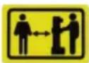
Only one person may remain in the working area of the log splitter, and the log splitter may be operated only by one person.
This appliance is intended solely for use in non-commercial applications. Any other use (as well as unauthorised conversions or add-ons) are regarded as contrary to the intended use and will result in exclusion of the warranty as well as loss of conformity (CE mark); the manufacturer will thus decline any responsibility for damage and/or injury suffered by the user or third parties.
2.2 Possible misuse
The following applications are expressly forbidden:
■ Splitting of freshly cut logs.
Splitting of logs in which metal parts such as nails, wire, staples, etc. are embedded.
■ Operation by more than one person
■ Operation in a potentially explosive atmosphere
2.3 Scope of supply
After unpacking, check whether all the parts have been delivered.

NOTE
A mains cable is not included in the scope of supply and must therefore be purchased separately.
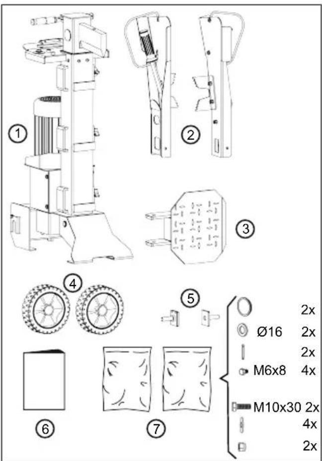
2.3.1 Scope of supply for LSV 6
2.3.2 Scope of supply for LSV 7 and LSV 8
| No. Component | |
| 1 Base unit | |
| 2 Operating arms (2x) | |
| 3 Splitting table | |
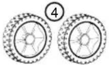
| 4 Wheels (2x) | |
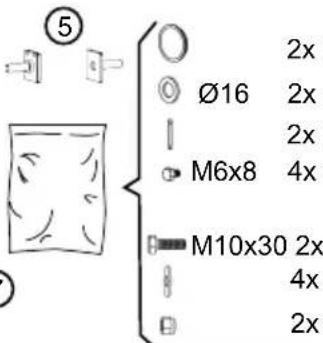
| 5 Wheel axles (2x) | |
| 6 Operating instructions | |
| 7 Bag with small parts (2x):■ 2 wheel caps, 2 washers ∅16, 2 cot-ter pins, 4 screws M6x8■ 2 screws M10x30, 4 washers ∅10, 2 self-locking nuts M10 |
| No. Component |
| 1 Base unit |
| 2 Operating arms (2x) |
| 3 Splitting table |
| 4 Wheels (2x) |
| 5 Splitting cross |
| 6 Operating instructions |
| 7 Bag with small parts (2x):■ 2 wheel caps, 2 wheel axles, 6 washers, 2 spring cotter pins■ 2 locking pins, 2 spring cotter pins |
2.4 Symbols on the appliance
Symbol Meaning

Read the operating instructions before starting operation!

Wear protective gloves!

Wear safety boots!

Wear protective glasses!

Keep your hands away from the danger area!
Disconnect the appliance from the mains before starting maintenance work!
Keep third parties away from the danger area!
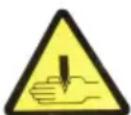
Keep your hands away from the danger area!
Keep your hands away from the danger area!

Remove or replace damaged parts!

Do not smoke!

Do not dispose of hydraulic oil in the countryside!
Symbol Meaning

Slipping hazard! Keep the working area clean!

Tripping hazard! Keep the working area clean!

Do not attach the appliance to a crane hook!
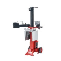
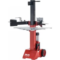
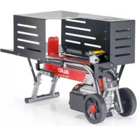
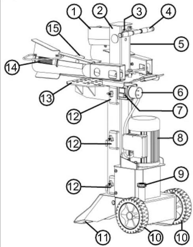
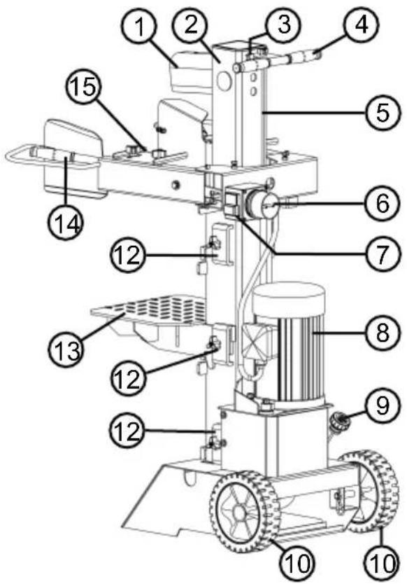
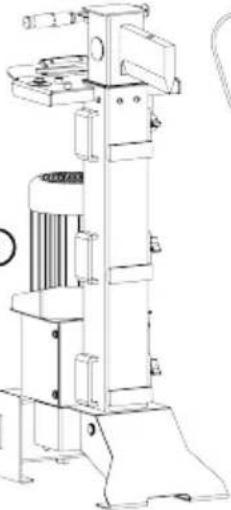
2.5 Product overview (01)
The log splitters consist of the following components:
No. Component
| 1 Splitting wedge |
| 2 Splitting column |
| 3 Locking screw for lifting rod |
| 4 Transport handle |
| 5 Lifting rod |
| 6 Mains plug socket |
| 7 Green and red buttons for ON/OFF |
| 8 Motor |
| 9 Vent plug and filler neck for hydraulic oil |
| 10 Transport wheels |
| 11 Bores for anchoring to the ground (LSV 6) |
| 12 Lateral brackets for splitting table |
| 13 Splitting table |
| 14 Operating arm with control lever and hand guard |
| 15 Retaining claws |
2.6 Safety and protective devices
Motor protection switch
The motor protection switch switches off the motor if the log splitter is overloaded. Do not deactivate the function of the motor protection switch. If the motor protection switch has switched off the log splitter, proceed as follows:
- Disconnect the log splitter from the mains.
- Determine the cause of the overload.
- Allow the log splitter to cool down for several minutes, then connect to the mains again.
- Switch on the log splitter.
Two-hand operation
The splitting wedge travels down only when both operating arms are actuated simultaneously. This eliminates the risk of the operator's hands being in the danger area.
2.7 Electrical connection

WARNING!
Risk of injury from elec- tric shock
A defective mains cable can result in serious injuries due to electric shock.
■ Ensure that the mains cable is not damaged or severed.
The maximum permissible cable length must not be exceeded. A longer cable impairs the motor power and hence the performance and function of the log splitter.
■ Mains cable, mains plug and coupling socket must be undamaged. A defective mains cable (e.g. with cracks, cuts, crushed or kinked points in the insulation) must not be used.
■ Repairs to the mains cable, mains plug and coupling socket may only be carried out by qualified electricians.
■ Do not expose plug connectors to moisture.
If the mains cable is damaged, immediately disconnect it from the mains.
Demands on the electrical connection
The mains power supply must be equipped with protective devices against low voltage, overvoltage, overload current (16 A) and an earth leakage circuit breaker (max. leakage current 0.03 A). Further demands on the electrical connection can be found in the technical data.
Requirements for the mains cable

NOTE
A mains cable is not included in the scope of supply and must therefore be purchased separately.
The mains cable must satisfy the following demands:
For LSV 6 and LSV 7:
Suitable for 230 V AC
■ 3 cores (1P + N + PE)
■ Maximum cable length: 10 m
For LSV 8:
Suitable for 400 V AC
■ 5 cores (3P + N + PE)
■ Maximum cable length: 10 m
3 SAFETY INSTRUCTIONS

DANGER!
Lack of knowledge of the safety instructions can pose a danger of extremely severe or even fatal injury.
Lack of knowledge of the safety instructions and operating instructions can lead to extremely serious and even fatal injury.
- Observe all safety instructions and instructions for use in these operating instructions as well the operating instructions which are referred to before you start using the appliance.
- Keep all supplied documents in a safe place for future reference.
3.1 Operator
■ Young people under 16 years of age and people who do not know the operating instructions are not allowed to use the appliance. Observe any country-specific safety regulations concerning the minimum age of the user.
■ Do not operate the appliance if you are under the influence of alcohol, drugs or medication.
3.2 Personal protective equipment
■ Wear clothing and protective equipment in accordance with the regulations in order to avoid injury to the head and limbs as well as to avoid hearing impairment.
The clothing must be appropriate (tightly fitting) and must not restrict movements. If you have long hair, it is essential to wear a hair net. Never wear loose items of clothing or accessories that be pulled into the appliance, e.g. scarves, loose-fitting shirts, long neck chains.
■ The personal protective equipment comprises:
■ Hearing protection and protective eyewear
■ Long trousers and sturdy shoes
■ Protective gloves
3.3 Safety in the workplace
■ Work only in daylight or under very bright artificial light.
■ Operate the appliance only on solid and level ground and not on sharp inclines.
■ Pay attention to stability.
3.4 Safety of persons, animals and property
■ Note that the user is responsible for accidents and damage that may befall other persons or their property.
■ Use the appliance only for the purposes for which it is intended. Any non-intended use can lead to injury and property damage.
■ Switch on the appliance only when there are no other persons or animals in the working area.
- Maintain a safe distance to persons or animals, or switch off the appliance if persons or animals approach.
3.5 Appliance safety
■ Use the appliance only under the following conditions:
■ The appliance is not soiled.
■ The appliance show no signs of damage.
■ All controls function properly.
- Do not overload the device. It is intended for light work in the private sector. Overload
can lead to damage to the ap-
pliance.
■ Never operate the appliance with worn or defective parts. Always replace defective parts with original spare parts from the manufacturer. If the appliance is operated with worn or defective parts, guarantee claims against the manufacturer are excluded.

NOTE
Repair work is only al- lowed to be carried out by expert workshops or our AL-KO service centres.
3.6 Electrical safety
■ The connection plug of the appliance must fit into the socket. The plug is not allowed to be changed in any way. Do not use any plug adapters together with earthed appliances. Unmodified plugs and matching sockets reduce the risk of electric shock.
- Avoid physical contact with earthed surfaces such as on pipes, heaters, cookers and refrigerators. There is an increased risk of electric shock if your body is earthed.
- Keep electrical tools out of the rain and away from moisture. Water getting into an electrical tool increases the risk of an electric shock.
- Do not use the cable for incorrect purposes such as carrying the electrical tool, hanging it up or for pulling the plug out of the socket. Keep the cable away from heat, oil, sharp edges or moving parts of the equipment. Damaged or tangled cables increase the risk of an electric shock.
If you are working outside with a power tool, only use extension leads that are also suitable for outside. Using an extension lead that is suitable for outside decreases the risk of electric shock.
If the operation of the power tool in a humid environment cannot be avoided, use a fault current circuit breaker. Using a fault current circuit breaker decreases the risk of electric shock.
3.7 Use and handling of the electrical tool
■ Do not overload the appliance. Use the appropriate electrical tool for the job
you are doing. Using the appropriate electrical tool will enable you to work more effectively and safely in the specified performance range.
- Do not use an electrical tool if it has a defective switch. An electrical tool that can no longer be switched on or off is dangerous and must be repaired.
■ Disconnect the plug from the socket and/or remove the battery before you make adjustments to the machine, change accessories or put the machine away. This precautionary measure will prevent the machine from starting inadvertently. - Keep unused electrical tools out of the reach of children. Do not allow people to use the machine if they are not familiar with it, or have not read these instructions. Power tools are dangerous if they are used by inexperienced people.
- Look after electrical tools with care. Check whether moving parts function perfectly and do not stick, whether there are any broken parts or parts that are damaged in such a way that
the function of the power tool is impaired. Have damaged parts repaired before you use the machine. Many accidents are caused by failure to maintain electrical tools properly.
- Keep cutting tools sharp and clean. Carefully maintained cutting tools with sharper cutting edges are less likely to stick and are easier to control.
■ Use electrical tools, accessories, insertion tools, etc. according to these instructions. When doing so, take account of the working conditions and the activity to be undertaken. Using electrical tools for applications other than the intended purpose can result in dangerous situations.
3.8 Safety instructions relating to operation
■ Never leave the operational appliance unsupervised.
■ Clean the appliance after every use.
■ Protect the appliance against unauthorised access.
■ The appliance may only be operated by one person.
■ Never move the appliance while the motor is running.
■ Never operate the appliance in rain or snow.
■ Disconnect the appliance from the mains for:
■ Maintenance and cleaning work
■ Adjustment work
Transport
■ Interruptions in work
Faults
■ Do not touch the splitting wedge.
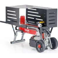
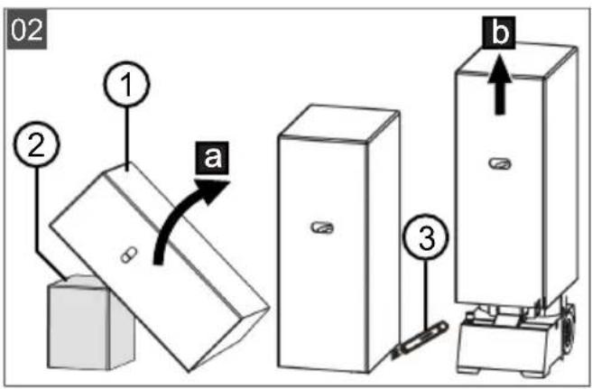
4 UNPACKING THE APPLIANCE (02)

WARNING!
Danger of crushing if the appliance tips over!
The appliance is heavy! If it tips over, limbs can be crushed and persons can be seriously injured.
■ At least two persons are required for unpacking the appliance!
■ Prevent the appliance from tipping over by placing blocks and wedges under the legs!
If the case with the log splitter is not already in an upright position:
- Lift case (02/1) on one side (02/a) with two persons. Take care that the case does not slip. If necessary: Push a block (02/2) under the opposite side to support the case.
- Raise the case until it is upright and straight.
- Cut open the case carefully on the underside using a knife (02/3), taking care that the appliance is not damaged.
- Lift the case off the appliance (02/b).
- Check the scope of supply (see chapter 2.3 "Scope of supply", page 31).
5 ASSEMBLY

WARNING!
Danger if assembly is not carried out completely!
Operation of an incom- pletely assembled appli- ance can result in serious injury.
■ Only operate the appliance when it is fully assembled.
- Check that all safety and protective devices are in place and functioning correctly before switching on.
5.1 Assembly for LSV 6
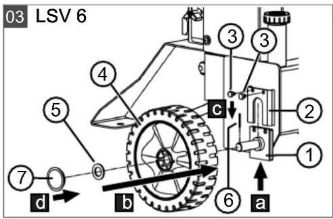
5.1.1 Installing wheels (03)
Perform the steps described here for both wheels:
- Push wheel axle (03/1) into holder (03/2) on the base unit from below (03/a) and hold tight.
-
To secure the wheel axle, screw two M6 x 8 screws (03/3) securely into the bores above one another in wheel axle and holder.
-
Push wheel (03/4) and washer (03/5) onto the wheel axle (03/b).
- Push cotter pin (03/6) through the bore in the wheel axle to prevent the wheel from falling off (03/c).
- Push on (03/d) wheel cap (03/7).
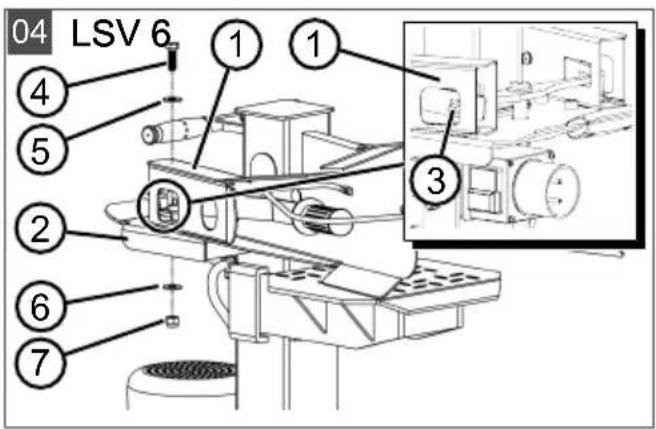
5.1.2 Installing operating arms (04)
Perform the steps described here for both operating arms:
- Place operating arm (04/1) on transverse plate (04/2) so that their mounting bores are aligned. Insert the lever of pump controller (04/3) into the recess in the operating arm.
Note: Pay particular attention that the lever of the pump controller is inserted correctly!
- Insert M10 x 30 screw (04/4) with washer (04/5) through the bores in operating arm and transverse plate.
- Push second washer (04/6) and self-locking nut (04/7) from below onto the screw and tighten securely.
5.2 Assembly for LSV 7 and LSV 8
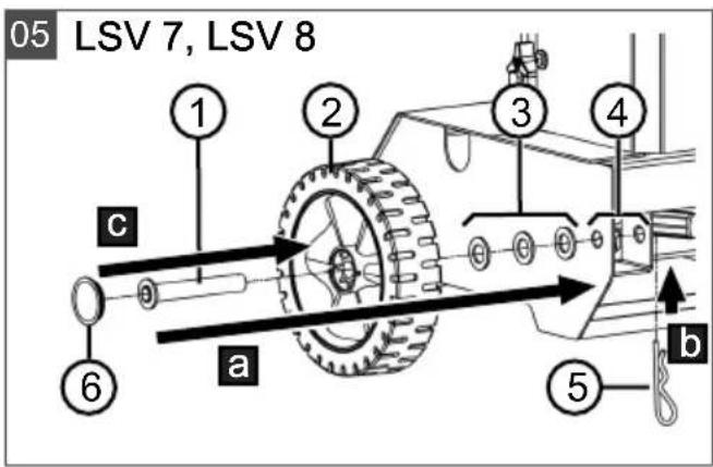
5.2.1 Installing wheels (05)
Perform the steps described here for both wheels:
- Push the following parts onto wheel axis (05/1):
Wheel (05/2)
■ 3 washers (05/3)
-
Push wheel axis with wheel and washers into bearing (05/4) as far as it will go (05/a).
-
Push spring cotter pin (05/5) through the bore in the wheel axle until it engages (05/b).
- Push on (05/c) wheel cap (05/6).
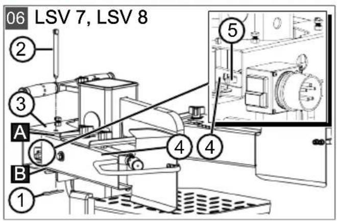
5.2.2 Installing operating arms (06)
Perform the steps described here for both operating arms:
- Pull spring cotter pin (06/1) out of locking pin (06/2).
- Pull locking pin out of transverse bracket (06/3).
- Coat operating arm (06/4) slightly with grease at points (06/A) and (06/B).
- Push operating arm (06/4) into transverse bracket (06/3) and onto the level of pump controller (06/5).
Note: Pay particular attention that the lever of the pump controller is inserted correctly!
- Insert locking pin (06/2) into the aligned bores of transverse bracket (06/3) and operating arm (06/4) as far as it will go.
- Push spring cotter pin (06/1) into the bore of locking pin (06/2) until it engages.
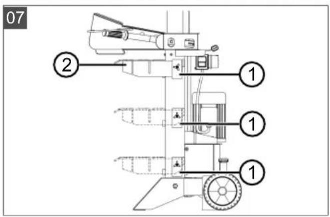
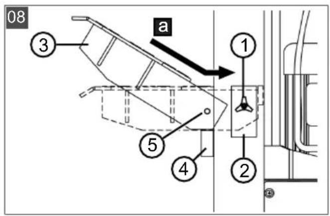
5.3 Installing splitting table (07, 08)
The splitting column has lateral brackets (07/1) at three heights for installation of splitting table (07/2) so that the height of the table can be adapted to the different lengths of the logs to be split.
- Loosen locking screw (08/1) of lateral bracket (08/2) until splitting table (08/3) can be pushed in.
- Position splitting table at an angle on fixing block (08/4) and push into the lateral bracket as far as it will go. Lower the splitting table onto the fixing block until it is finally in the horizontal position (08/a).
- Insert the locking screw through bore (08/5) of the splitting table to fix it in place.
Proceed analogously in reverse order to remove the splitting table.
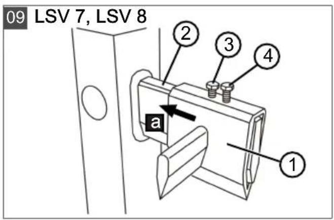
5.4 Installing splitting cross [LSV 7, LSV 8] (09)
- Push splitting cross (09/1) onto splitting wedge (09/2) as far as it will go (09/a).
- Insert screw (09/3) into the bore of the splitting wedge to secure the splitting cross.
- Tighten screw (09/4) securely to push the splitting cross upwards.
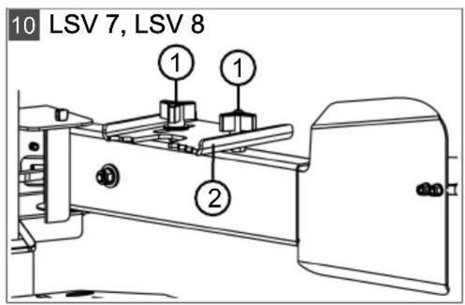
5.5 Adjusting retaining claws [LSV 7, LSV 8] (10)
Each operating arm has a retaining claw. The retaining claws can be adjusted according to the diameter of the logs to be split. Adjust both retaining claws to the same dimension:
- Loosen both locking screws (10/1) of retaining claw (10/2).
- Push retaining claw (10/2) to the required dimension.
- Tighten both locking screws (10/1).
6 START-UP
6.1 Setting up and connecting log splitter

DANGER!
Risk of electric shock if the log splitter is operated without residual current circuit breaker
Operation of the appliance without residual current circuit breaker in the mains connection can result in serious injuries or even death due to electric shock.
■ Before connecting the appliance, check whether the mains connection has a residual current circuit breaker for a maximum leakage current of 0.03 A.
If you cannot be sure that a residual current circuit breaker is installed: Use an additional portable residual current device with switched PE conductor.

WARNING!
Danger of injury if the appliance tips over
A tipping appliance can result in serious injury and damage to the appliance.
■ Ensure that the appliance cannot tip over.
- Stand the log splitter horizontally on a level, firm surface. Do not place the log cutter on the mains cable!
Note: Do not place any material under the log splitter to change the height of the appliance or to try to increase its stability. If the log splitter is not level and/or is unstable, it must be moved to another location. Operation on soft ground such as lawns or gravel is not permitted as the appliance could sink in and/or tip over during operation. - Lay the mains cable in such a way that it cannot be kinked, crushed or damaged in any other way.
- Plug the mains cable into plug socket (01/6) of the appliance and then connect the mains cable to the mains power supply.
Note: During disconnection, first disconnect the mains cable from the mains power supply.
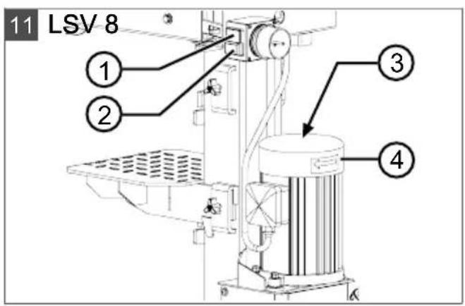
6.2 Check direction of rotation of motor [LSV 8] (11)
IMPORTANT!
Danger of damage to the hydraulic pump
The hydraulic pump will be damaged if the motor rotates in the wrong direction.
■ Switch off the log splitter again immediately if the motor rotates in the wrong direction or the splitting wedge does not move upwards after switching on.
■ Reverse the phases of the mains voltage.
- At the same time:
■ Press green button (11/1) and then red button (11/2) to allow the motor to run briefly.
- Observe the direction of rotation of the motor through ventilation slots (11/3). The direction of rotation must correspond to the arrow (11/4) on the motor.
- If the direction of rotation does not correspond: see chapter 6.3 "Reversing phases of the mains voltage [LSV 8] (12)", page 41.
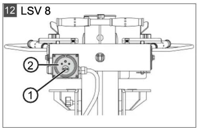
6.3 Reversing phases of the mains voltage [LSV 8] (12)
- Switch off the log splitter immediately and unplug the mains cable.
- Insert a flat-tip screwdriver into phase inverter (12/1) in mains plug socket (12/2) of the log splitter.
- Press in the phase inverter and turn by 180^ .
- Plug in the mains cable.
- Switch on the log splitter and check the direction of rotation of the motor again. The splitting wedge must move upwards.
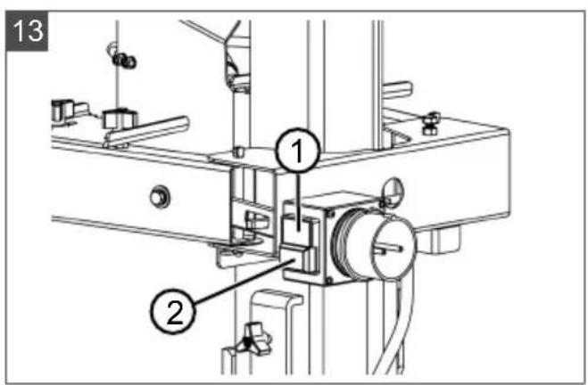
6.4 Carry out function check (13)
- Press green button (13/1) to switch on. The splitting wedge automatically moves upwards.
If the splitting wedge is already in the uppermost position, briefly press both operating arms downwards, then switch the log splitter off and on again. Press red button (13/2) to switch off.
- On LSV 8, if the splitting wedge does not move upwards: Switch off the log splitter immediately to prevent appliance damage. Check direction of rotation of the motor and correct, if necessary (see chapter 6.2 "Check direction of rotation of motor [LSV 8] (11)", page 41).
- Carry out function check:
■ Press both operating arms downwards simultaneously. The splitting wedge must move downwards and stop approx. 5 cm above the uppermost table position.
■ Release one of the operating arms. The splitting wedge must stop in the momentary position.
■ Release both operating arms simultaneously. The splitting wedge moves upwards.
- If it is very cold, allow the log splitter to run at idle speed for approx. 15 min. to allow the hydraulic oil to warm up.
7 OPERATION

WARNING!
Risk of injury if operated by more than one person
Operation of the appliance by two or more persons can result in serious injuries.
■ Operate the appliance only alone.
- Keep other persons away and in particular prevent them from reaching into the log that is currently being split.
IMPORTANT!
Risk of damage from im- proper use
Improper splitting of the logs can result in damage or destruction of the appliance.
■ Always place the log on the splitting table perpendicularly, i.e. in the direction of the wood grain, never at right angles.
■ Never try to force a log to split by maintaining the hydraulic pressure for several seconds.

WARNING!
Risk of injury from shattering log
Stored hardwood, irregular branches, irregular logs and logs with a large number of knots tend to shatter during splitting. Flying pieces of wood can then cause serious injuries.
Split only straight logs with a perpendicular and straight cutting surface.
■ Wear the prescribed protective clothing at all times.

NOTE
■ Always split only well-dried logs. These can be split far easier than fresh, moist wood.
■ Very thick logs can be split more easily if they are not too long.
7.1 Before each use

WARNING! Danger of injury from faulty appliance
Operation of an faulty appliance can result in serious injury and damage to the appliance.
■ Operate the appliance only when it is undamaged and has not defects, and when no parts are missing or loose.
- Carry out a visual inspection of the log splitter.
The log splitter must not be switched on if parts of the appliance are missing, defective or loose.
- Carry out a visual inspection of the mains cable.
A defective mains cable (e.g. with cracks, cuts, crushed or kinked points in the insulation) must not be used.
- Carry out a visual inspection for leaks in the hydraulic system.
■ The log splitter must not be switched on if the hydraulic system has leaks.
-
Clean and then grease the sliding surfaces of the splitting column and splitting wedge (see chapter 8.1.1 "Grease sliding surfaces (16)", page 45).
-
Carry out a function check of the operating arms (see chapter 6.4 "Carry out function check (13)", page 42).
7.2 Adjusting the splitting table
- Adjust the splitting table to the height of the logs to be split (see chapter 5.3 "Installing splitting table (07, 08)", page 40).
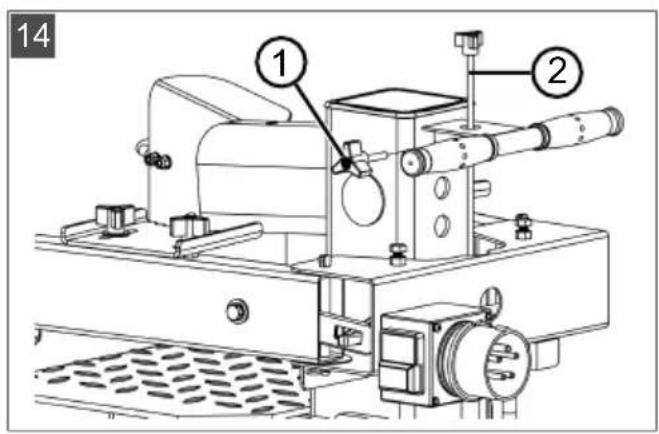
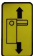
7.3 Adjusting the stroke limiter (14)
- Place the log onto the splitting table.
-
Press both operating arms down to move the splitting wedge down.
-
When the splitting wedge is approx. 3 - 5 cm above the log: Release one operating arm to stop the splitting wedge in its momentary position.
- Switch off the appliance.
- Loosen locking screw (14/1) and pull lifting rod (14/2) completely up.
- Tighten the locking screw again.
- Switch on the appliance. The splitting wedge moves upwards.
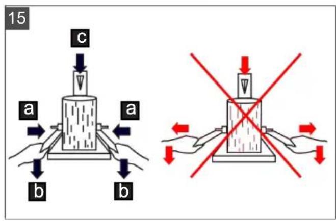
7.4 Splitting log (15)

CAUTION!
Risk of injury due to un- tidy workplace
Untidiness and logs lying around pose a risk of tripping and slipping in the working area.
■ Store the logs to be split in a tidy pile.
- Immediately remove split logs and wood chips from the working area.
- For LSV 7 and LSV 8: Adjust the retaining claws to the diameter of the logs to be split (see chapter 5.5 "Adjusting retaining claws [LSV 7, LSV 8] (10)", page 40).
- Place the log absolutely perpendicularly onto the splitting table.
Note: The log must stand freely on the splitting table. Never try to split crooked logs!
Press both operating arms together simultaneously so that the log is clamped (15/a). - Press both operating arms down simultaneously (15/b). The splitting wedge moves down (15/c).
- When the splitting wedge can completely split the log: Release both operating arms so that the splitting wedge moves up.
- Remove the split logs from the working area.
7.5 Removing a jammed log

CAUTION!
Risk of injury from a jammed log flying out
If a jammed log flies out of the appliance, injuries can be caused and the appli-ance may be damaged.
■ Never try to free a jammed log using tools.
- Allow the splitting wedge to travel up completely.
- Position a wedge-shaped log on the splitting table.
- Allow the splitting wedge to travel down. The jammed log is forced forwards by the wedge-shaped log.
- Repeat the steps above with larger wedges in turn until the jammed log is freed.
8 MAINTENANCE AND CARE

WARNING!
Risk of injury during maintenance work
Improper maintenance can result in serious injury and damage to the appliance.
■ Disconnect the appli- ance from the mains be- fore starting mainte- nance work.
■ Have repairs to the appliance carried out only by qualified companies.
8.1 Maintenance and care work
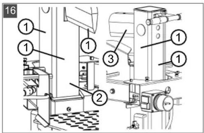
8.1.1 Grease sliding surfaces (16)
Grease the sliding surfaces at regular intervals, particularly when splitting very resin y logs:
- Clean sliding surfaces (16/1) of splitting column (16/2) and splitting wedge (16/3).
- Grease the sliding surfaces with a resin and acid-free grease.
8.2 Maintenance tasks
8.2.1 Sharpening the splitting wedge
If the splitting wedge has become blunt after a long period of use:
- Remove material deposits on the splitting wedge using a suitable file and then sharpen the splitting wedge.
- Apply oil or lubricant to the sharpened surfaces.
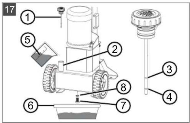
8.2.2 Checking and topping up hydraulic oil (17)
Check the oil level every day and change the hydraulic oil after 1 year or 150 operating hours. Use only hydraulic oil HLP 46 for topping up and changing.
IMPORTANT!
Risk of appliance damage from use of wrong hydraulic oil
Use of the wrong hydraulic oil and oil levels that are too high or too low result in malfunctions and heat development and can damage the hydraulic pump.
■ Use only the prescribed hydraulic oil.
- Check the hydraulic oil level at regular intervals and top up, when necessary.
- Stand the log splitter upright and disconnect from the mains power supply.
- Allow the log splitter to stand for a few minutes so that the oil can settle in the oil tank.
- Unscrew oil dipstick (17/1) from oil filler neck (17/2) and wipe using a clean, lint-free cloth.
Check the oil level
- Insert the dipstick up to the stop and pull out again.
- Read off the oil level from the dipstick. The oil level must be between the upper (17/3) and lower (17/4) mark.
Top up hydraulic oil
If the oil level is below the lower mark:
- Pour in hydraulic oil (17/5) through the oil filler neck. Use a funnel, if necessary. Do not allow any foreign particles to get into the oil tank!
- Check the oil level (see above).
- Screw in the dipstick again and tighten slightly.
Change hydraulic oil
The complete hydraulic oil must be changed once a year.
- Place oil drip tray (17/6) under the log splitter.
- Unscrew oil drain plug (17/7) with seal ring (17/8) and allow all the oil to drain into the oil drip tray. Dispose of the old oil in the prescribed manner!
- Place a seal ring on the oil drain plug and screw in the drain plug tightly.
- Pour in hydraulic oil (see above).
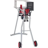
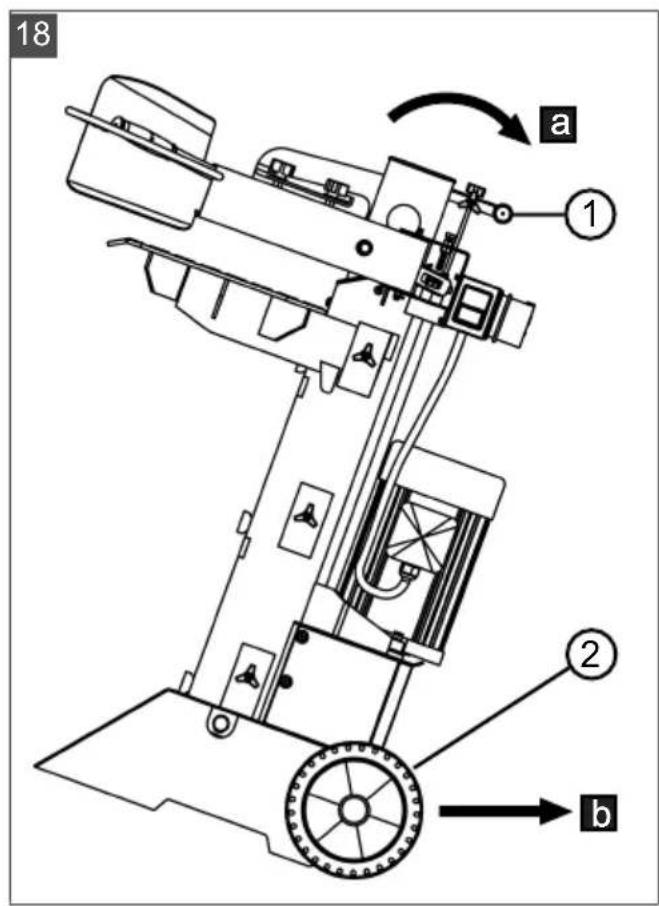
9 TRANSPORT (18)
IMPORTANT!
Danger of damage to the appliance due to improper transport
Improper transport can result in damage to the appliance.
■ Remove the mains plug at all times before transport.
■ Pull the appliance at a slight angle using the transport handle.
- When using a crane: Do not lift the appliance at individual components or at the transport handle! Use a sturdy sling for lifting.

WARNING!
Danger of crushing if the appliance tips over!
The appliance is heavy! If it tips over, limbs can be crushed and persons can be seriously injured.
■ Transport the appliance with the greatest care.
■ Move any obstacles out of the planned transport route.
- Grip the log splitter with both hands at transport handle (18/1) and tilt slightly so that it is resting (18/a) on the wheels (18/2).
- Pull the log splitter to the required location (18/b) using the transport handle.
10 STORAGE
- Disconnect the log splitter from the mains.
- Thoroughly clean the appliance after each use and – if present – attach all covers. The splitting wedge must be in the end position.
- Store the appliance in a dry, lockable place out of the reach of children.
11 DISPOSAL
Information on the German Electrical and Electronic Equipment Act (ElectroG)

■ Electrical and electronic appliances do not belong in household waste, but should be collected and disposed of separately.
■ Used batteries or rechargeable batteries that are not installed permanently in the old appliance must be removed before disposal. Their disposal is regulated by the battery law.
- Owners or users of electrical and electronic appliances are obliged by law to return them after use.
The end user bears personal responsibility for deleting his personal data from the old appliance to be disposed of.
The symbol of the crossed-through rubbish bin means that electrical and electronic appliances may not be disposed of in the household rubbish. Electrical and electronic appliances can be handed in at no charge at the following places:
■ Public service disposal or collection points (e.g. municipal building yards)
■ Points of sale of electrical appliances (stationary and online) provided traders are obliged to take them back or offer this voluntarily.
These statements only apply to appliances that are installed and sold in the countries of the European Union and are subject to European Directive 2012/19/EU. Different provisions may apply to the disposal of electrical and electronic appliances in countries outside the European Union.
12 AFTER-SALES / SERVICE
In the event of questions of warranty, repair or spare parts, please contact your nearest AL-KO Service Centre.
These can be found on the Internet at:
www.al-ko.com/service-contacts
13 HELP IN CASE OF MALFUNCTION
In the event of malfunctions, switch off the log splitter immediately and remove the mains plug!

CAUTION! Risk of injury
Sharp-edged and moving appliance parts can lead to injury.
■ Always wear protective gloves during maintenance, care and cleaning work.
| Malfunction Cause Remedy | ||
| Motor does not start. Motor protection switch has tripped. | Wait until the motor has cooled down. | |
| Mains plug or plug socket defective | ||
| Defective mains cable Have inspected and replaced, if necessary, by a qualified electrician. | ||
| Defective motor Have inspected and replaced, if necessary, by a qualified electrician. | ||
| Green ON button does not latch when pressed in | No PE conductor or a phase not connected. | Have inspected and replaced, if necessary, by a qualified electrician. |
| Defective switch | ||
| Splitting wedge does not move up/down, but motor is running. | Insufficient hydraulic oil Top up hydraulic oil. | |
| Defective hydraulic pump | Have replaced by a specialist company or AL-KO service centre. | |
| Valve not open caused by loose connection. | Tighten loose parts. | |
| Operating lever or connecting parts bent | Have bent parts repaired. | |
| For LSV 8: Wrong direction of rotation of the motor caused by incorrect phase connection of the mains voltage | Reverse the phases of the mains voltage at the plug socket of the log splitter.Have inspected and corrected, if necessary, by a qualified electrician. | |
| Splitting wedge has no force. Insufficient hydraulic oil Top up hydraulic oil. | ||
| Bent actuating lever | Have replaced by a specialist company or AL-KO service centre. | |
| Unusual noises and vibrations Insufficient hydraulic oil Top up hydraulic oil. | ||
| Hydraulic pump whistles, splitting wedge moves jerkily. | Insufficient hydraulic oil Top up hydraulic oil. | |
| Air in hydraulic circuit Loosen vent plug. | ||
| Motor becomes very hot. Inadequate cable cross-section of an extension lead | Use an extension lead with a larger cable cross-section. | |
| Missing phase Have inspected and corrected, if necessary, by a qualified electrician. | ||

NOTE
If you encounter any malfunctions that are not listed in this table or that you cannot rectify yourself, please contact our customer service.
14 GUARANTEE
We will resolve any material or manufacturing faults on the appliance during the legal warranty period for claims relating to faults, in accordance with our choice either to repair or replace. The legal warranty period is determined by the legislation of the country in which the appliance was purchased.
Our warranty promise applies only if:
■ These operating instructions are heeded
■ The appliance is handled correctly
■ Original spare parts have been used
The warranty becomes void in the case of:
■ Unauthorised repair attempts
■ Unauthorised technical modifications
Non-intended use
The guarantee excludes:
■ Paint damage that can be attributed to normal wear and tear
■ Wear parts that are marked with a frame xxxxxx (x) on the spare parts card
The guarantee period commences with purchase by the first end user. The date on the proof of purchase is decisive. In the event of a guarantee claim, please take this guarantee declaration and the original proof of purchase, and contact your dealer or the nearest authorised customer service centre. This statement does not affect the purchaser's statutory claims for defects against the vendor.
15 EU DECLARATION OF CONFORMITY
We hereby declare that this product in its marketed form conforms to the requirements of the harmonised EU Directives, EU safety standards and the product-specific standards.
| Product | Manufacturer | Duly authorised person for technical file | |
| Log splitter | AL-KO Geräte GmbH | Andreas Hedrich | |
| Serial number | Ichenhauser Str. 14 | Ichenhauser Str. 14 | |
| G4032012 | D-89359 Kötz | D-89359 Kötz | |
| Germany | Germany | ||
| Type | EU directives | Harmonised standards | |
| LSV 6 | 2006/42/EC | EN 60204-1:2006+A1:2009 | EN 55014-2:1997+A2:2008 |
| LSV 7 | 2014/30/EU | EN 609:1999+A2:2009 | EN 61000-3-2:2014 |
| LSV 8 | 2011/65/EU | EN 55014-1:2006+A2:2011 | EN 61000-3-11:2000 |
Kötz, 17/08/2017

Wolfgang Hergeth
Managing Director
TRADUCTION DE LA NOTICE D'UTILISATION ORIGINALE
Table des matières
www.al-ko.com/service-contacts
13 AIDE EN CAS DE PANNES
15 DÉCLARATION DE CONFORMITÉ CE
www.al-ko.com/service-contacts
13 SUPPORTO IN CASO DI ANOMALIE
2 PRODUCTOMSCHRIJVING
Nr. Component
Nr. Component
Wolfgang Hergeth Managing Director
www.al-ko.com/service-contacts
13 AYUDA EN CASO DE AVERÍA
Nr. Komponent
| 1 Basenhet |
| 2 Manöverarmar (2 st) |
| 3 Klyvbord |
| 4 Hjul (2 st) |
| 5 Instickbara axlar (2 st) |
| 6 Bruksanvisning |
| 7 Påsar med smådelar (2 st):■ 2 st navkapslar, 2 st distansbrickor ∅16, 2 st sprintar, 4 st skruvar M6x8■ 2 st skruvar M10x30, 4 st distans-brickor ∅10, 2 st låsmuttrar M10 |
natural_image
Technical line drawing of a vertical industrial machine with no visible text or symbols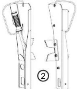
natural_image
Technical line drawing of a mechanical device with two views (top and side), no visible text or symbols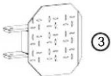
Nr. Komponent
| 1 Basenhet |
| 2 Manöverarmar (2 st) |
| 3 Klyvbord |
| 4 Hjul (2 st) |
| 5 Klyvkors |
| 6 Bruksanvisning |
| 7 Påsar med smådelar (2 st):■ 2 st navkapslar, 2 st instickbara ax-lar, 6 st distansbrickor, 2 st fjä-dersprintar■ 2 st spärrstift, 2 st fjädersprintar |
■ 2 st navkapslar, 2 st instickbara axlar, 6 st distansbrickor, 2 st fjädersprintar
■ 2 st spärrstift, 2 st fjädersprintar
9 Transport (18) 200
10 Opbevaring 200
11 Bortskaffelse 200
12 Kundeservice/service.... 201
13 Hjælp ved fejl 202
14 Garanti 203
15 EF-overensstemmelseserklæring 203
1 OM DENNE BRUGSANVISNING
www.al-ko.com/service-contacts
13 HJÆLP VED FEJL
Wolfgang Hergeth Managing Director
OVERSETTELSE AV DEN ORIGINALE BRUKSANVISNINGEN
Innhold
1 Om denne bruksanvisningen 206
1.1 Tegnforklaringer og signalord.... 206
2 Produktbeskrivelse 206
2.1 Tiltenkt bruk.... 206
2.2 Mulig feil bruk 206
2.3 Leveransens omfang.... 206
2.3.1 Leveringsomfang for LSV 6.... 207
2.3.2 Leveringsomfang for LSV 7 og LSV 8 207
2.4 Symboler på maskinen.... 207
2.5 Produktoversikt (01) 208
2.6 Sikkerhets- og beskyttelsesanordninger 208
2.7 Elektrisk tilkobling.... 209
8.1.1 Smøre glideflater (16).... 219
8.2 Vedlikeholdsarbeider 219
9 Transport (18) 220
10 Oppbevaring 220
11 Avfallshändtering 220
12 Kundeservice/service.... 221
13 Feilsøking 222
14 Garanti 223
15 EC-samsvarserklæring 223
1 OM DENNE BRUKSANVISNINGEN
5.1 Montering for LSV 6
5.1.1 Montere hjulene (03)
8 VEDLIKEHOLD OG PLEIE

ADVARSEL!
8.1.1 Smøre glideflater (16)
www.al-ko.com/service-contacts
13 FEILS∅KING
Wolfgang Hergeth Managing Director
LSV 6
LSV 7
LSV 8
natural_image
Pure electrical circuit lines without any symbols