
GSN 9034 DK Professional - Stapler BOSCH - Free user manual and instructions
Find the device manual for free GSN 9034 DK Professional BOSCH in PDF.
| Product type | Pneumatic stapler/nailer |
| Brand | Bosch |
| Model | GSN 9034 DK Professional |
| Dimensions (H × W × D) | 355 × 105 × 485 mm |
| Weight (per EPTA 01/2003) | 3.8 kg |
| Air supply | Compressed air (nominal pressure 4–8 bar) |
| Air connection | Thread 3/8", inner hose Ø 3/8", max. length 30 m |
| Magazine capacity | Up to 99 staples/nails |
| Permitted fastener length | 50–90 mm |
| Permitted fastener diameter | 2.8–3.8 mm |
| Magazine angle | 34° |
| Trigger modes | Single sequential actuation with anti-dry fire / Contact actuation |
| Striking power (at 6.3 bar) | 96 Nm |
| Air consumption (per cycle at 6.8 bar) | 3.02 L |
| Sound pressure level (EN 12549) | 110 dB(A) – Wear hearing protection |
| Sound power level (EN 12549) | 123 dB(A) |
| Vibration (EN 28662 / EN ISO 8662) | < 2.5 m/s² (uncertainty K = 1.5 m/s²) |
| Spare parts and repairability | Spare parts available from Bosch service; repair by qualified personnel |
| Maintenance and cleaning | Clean magazine and pusher rod; lubricate regularly (SAE 10 or SAE 20 oil) |
| Safety | Contact arm, trigger lock, lockable contact actuation, air shut‑off before maintenance |
Frequently Asked Questions - GSN 9034 DK Professional BOSCH
User questions about GSN 9034 DK Professional BOSCH
0 question about this device. Answer the ones you know or ask your own.
Ask a new question about this device
Download the instructions for your Stapler in PDF format for free! Find your manual GSN 9034 DK Professional - BOSCH and take your electronic device back in hand. On this page are published all the documents necessary for the use of your device. GSN 9034 DK Professional by BOSCH.
USER MANUAL GSN 9034 DK Professional BOSCH
YkpaHcbKa ..CtoPiHa 229
Romana.. 241
BbIrapckn. CtpaHua 253
Srpski. Strana 267
Slovensko. Stran 278
Dr. Egbert Schneider Senior Vice President Engineering
Dr. Eckerhard Strötgen
Head of Product Certification
Paa.
Robert Bosch GmbH, Power Tools Division
D-70745 Leinfelden-Echterdingen
Leinfelden, 08.12.2009
Montage
General Safety Rules for Pneumatic Tools
WARNING Read and observe all safety warnings and instructions. Failure to follow the following safety warnings and instructions may result in electric shock, fire and/or serious injury.
Save all warnings and instructions for future reference.
1) Work area safety
a)Keep work area clean and well lit. Cluttered or dark areas invite accidents.
b)Do not operate the pneumatic tool in explosive atmospheres, such as in the presence of flammable liquids, gases or dusts. While working the workpiece, sparks can be created which may ignite the dust or fumes.
c)Keep children and bystanders away from your workplace while operating the pneumatic tool. Distractions from other persons can cause you to lose control over the pneumatic tool.
2) Pneumatic tool safety
a) Use compressed air of Quality Class 5 in accordance with DIN ISO 8573-1 and a separate maintenance unit close to the pneumatic tool. The compressed air supplied should be free of foreign material and moisture to protect the pneumatic tool from damage, contamination, and the formation of rust.
b)Check the connections and the air supply lines. All maintenance units, couplers, and hoses should conform to the product specifications in terms of pressure and air volume. Too low pressure impairs the function of the pneumatic tool; too high pressure can result in material damage and personal injury.
c)Protect the hoses from kinks, restrictions, sol- vents, and sharp edges. Keep the hoses away from heat, oil, and rotating parts. Immediately replace a damaged hose. A defective air supply line may result in a wild compressed-air hose and can cause personal injury. Raised dust or chips may cause serious eye injury.
d)Make sure that hose clamps are always tightened firmly. Loose or damaged hose clamps may result in uncontrolled air escape.
3) Personal safety
a)Stay alert, watch what you are doing, and use common sense when operating a pneumatic tool. Do not use a pneumatic tool while tired or under the influence of drugs, alcohol, or medication. A moment of inattention while operating a pneumatic tool may result in personal injury.
b)Use personal protective equipment. Always wear eye protection. Protective equipment such as dust mask, non-skid safety shoes, hard hat, or hearing protection used for appropriate conditions will reduce personal injuries.
c)Prevent unintentional starting. Make sure that the pneumatic tool is switched off before connecting it to the air supply, picking it up or carrying it. When your finger is on the On/Off switch while carrying the pneumatic tool or when connecting the pneumatic tool to the air supply while it is switched on, accidents can occur.
d)Remove any adjustment tools before switching on the pneumatic tool. A wrench or key left attached to a rotating part of a pneumatic tool may result in personal injury.
e)Do not overreach. Keep proper footing and balance at all times. This enables better control of the pneumatic tool in unexpected situations.
f) Dress properly. Do not wear loose clothing or jewellery. Keep your hair, clothing and gloves away from moving parts. Loose clothes, jewellery or long hair can be caught in moving parts.
g)If devices are provided for the connection of dust extraction and collection facilities, ensure these are connected and properly used. Use of dust collection can reduce dust-related hazards.
h)Do not directly inhale the exhaust air. Avoid exposing the eyes to exhaust air. The pneumatic tool's exhaust air can contain water, oil, metal particles and debris from the compressor. This can cause damage to one's health.
4) Pneumatic tool use and care
a)Use the clamping devices or a vice to secure and support the workpiece. Holding the workpiece by hand or against your body will not allow for safe operation of the pneumatic tool.
b)Do not overload the pneumatic tool. Use the pneumatic tool intended for your work. The correct pneumatic tool will do the job better and safer at the rate for which it is designed.
c) Do not use a pneumatic tool that has a defective On/Off switch. A pneumatic tool that cannot be controlled with the switch is dangerous and must be repaired.
d) Disconnect the air supply before making any adjustments, changing accessories, or placing the pneumatic tool aside. This safety measure prevents accidental starting of the pneumatic tool.
e)Store idle pneumatic tools out of the reach of children. Do not allow persons unfamiliar with the pneumatic tool or these instructions to operate the device. Pneumatic tools are dangerous in the hands of untrained users.
f) Maintain the pneumatic tool with care. Check for misalignment or binding of moving parts, breakage of parts and any other condition that may affect the pneumatic tool's operation. Have damaged parts repaired before using the pneumatic tool. Many accidents are caused by poorly maintained pneumatic tools.
g)Use the pneumatic tool, accessories, application tools, etc. according to these instructions. Take into consideration the working conditions and the activities to be carried out. Use of the pneumatic tool for operations different from those intended could result in hazardous situations.
5) Service
a)Have your pneumatic tool repaired only through a qualified repair person and only using original replacement parts. This will ensure that the safety of the pneumatic tool is maintained.
SafetyWarnings for Compressed-air Nailers/Staplers

Wear safety goggles.
Always assume that the pneumatic tool is loaded with fasteners. Careless handling of the pneumatic tool can lead to unexpected shot actuation of fasteners and cause injury.
When working, hold the pneumatic tool in such a manner that your head and body cannot be injured in case of sudden kickback due to a malfunction of the energy supply or from hard objects/locations in the workpiece.
Never point the pneumatic tool at yourself or at persons close by. Unexpected actuation will expel a fastener, which can lead to injury.
Do not actuate the pneumatic tool until firmly placed against the workpiece. When the pneumatic tool is not in contact with the workpiece, the fastener can bounce away from the fastening point and overload the pneumatic tool.

Do not work on ladders or scaffolds when the actuation system "Contact actuation" is set. In particular, do not move from one fastening location to another, close boxes or enclosures, or fasten transport-securing fixtures on e.g., vehicles and wagons, via scaffolds, stairs, ladders or ladder-like constructions, such as roof battens. With this actuation system, a fastener will be discharged each time when accidentally applying the pneumatic tool while the discharge lock-off is pressed in. This can lead to injury.
Observe the conditions of the job site. It is possible that fasteners can burst through thin workpieces or be deflected when working in corners or against edges, and harm persons.

Disconnect the air supply, when the fastener is jammed in the pneumatic tool. When the pneumatic tool is still connected to the power supply, it can accidentally be actuated when removing a jammed fastener.
Use caution when removing a jammed or stuck fastener. The system can be under tension and cause the fastener to be shot or thrust out, while attempting to clear the jam.
22 | English
Do not use this to pneumatic tool to fasten electrical wiring. It is not suitable for fastening electrical wiring, can damage the insulation of electric cables and thus lead to electric shock and danger of fire.
Never use oxygen or flammable gases as the energy source for the pneumatic tool. Flammable gases are dangerous and can cause the pneumatic tool to explode.
- Use appropriate detectors to determine if utility lines are hidden in the work area or call the local utility company for assistance. Contact with electric lines can lead to fire and electric shock. Damaging a gas line can lead to explosion. Penetrating a water line causes property damage or may cause an electric shock.
The pneumatic tool may only be connected to lines, for which the maximal permissible pressure of the pneumatic tool cannot be exceeded by more than 10% ; for higher pressures, a pressure control valve (pressure reducer) with preceding pressure-limitation valve in the compressed-air line must be installed. Excessive pressure leads to abnormal operation or breakage of the pneumatic tool, which can lead to injury.
Functional Description

Read all safety warnings and all instructions.
Failure to follow the warnings and instructions may result in electric shock, fire and/or serious injury.
Intended Use
The pneumatic tool is intended for connecting work in roofing, encasing, battening, manufacturing wall and ceiling elements, wood facades, pallets, wood fences, noise-reduction walls and boxes.
Only the fasteners (nails, staples, etc.) specified in table "Technical Data" may be used.
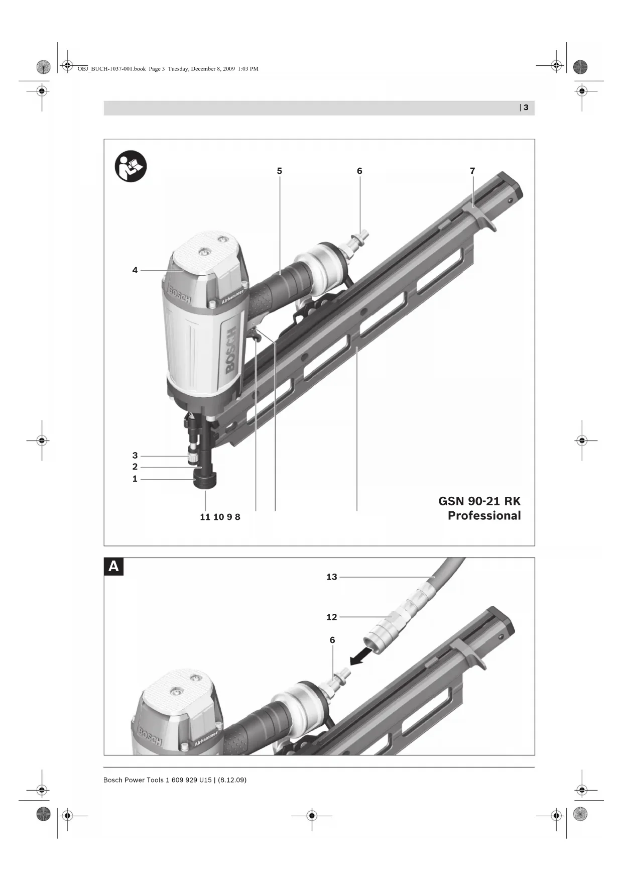
Product Features
The numbering of the product features refers to the illustration of the pneumatic tool on the graphics page.
1 Workpiece protector
2 Discharge lock-off
3 Depth stop
4 Air outlet
5 Handle
6 Air connector
7 Magazine slider
8 Magazine
9 Selector switch for actuation system
10 Trigger
11 Outlet
12 Air-connection coupling
13 Supply-air hose
14 Nail strip
15 Magazine lock
16 Lock pin
17 Driver blade
18 Magazine holder
19 Magazine retainer at shot duct
20 Magazine rail
21 Locking screw
22 Cover lid
23 Spring clip
24 Screwable eyelet for pneumatic tool suspension
Accessories shown or described are not part of the standard delivery scope of the product. A complete overview of accessories can be found in our accessories program.
English | 23
Technical Data
| Compressed-air nailer GSN 90-21 RK | GSN 90-34 DK | ||
| Professional | Professional | ||
| Article number | 3601D910...3601D913.. | ||
| Driving forceat 6.3 bar (91 psi) | Nm 98 96 | ||
| Actuation systems- Single actuation with safety run | ● | ● | |
| - Contact actuation | ● | ● | |
| Fastener- Type | Nail strip Plastic-bonded Round head | Nail strip Paper-bonded D-head | |
| - Length | mm | 50-90 | 50-90 |
| -Diameter | mm | 2.8-3.8 | 2.8-3.8 |
| Magazine angle | ° | 2 | 1 |
| Magazine capacity, max. 73 99 | |||
| Engine oilS A E 10 , S A E 20 | ml | 0.25-0.5 | 0.25-0.5 |
| Internal volume | ml 997 997 | ||
| Rated pressure | bar | 4-8 | 4-8 |
| Connecting thread | " | 3/8 | 3/8 |
| Supply-air hose- Max. operating pressure at 20 °C | bar | 10 | 10 |
| - Inner diameter of hose | " | 3/8 | 3/8 |
| - Max. hose length | m | 30 | 30 |
| Air consumption per driving procedureat 6.8 bar (100 psi) | I | 3.02 | 3.02 |
| Dimensions | |||
| - Height | mm | 342 | 355 |
| - Width | mm | 105 | 105 |
| - Length | mm | 542 | 485 |
| Weight according to EPTA-Procedure 01/2003 | kg | 3.89 | 3.8 |
Noise/Vibration Information
Measured noise values determined according to EN 12549.
Typically the A-weighted noise levels of the pneumatic tool are: Sound pressure level 110 dB(A); sound power level 123 dB(A). Uncertainty K = 2 dB.
Wear hearing protection!
Overall vibrational values (vector sum of three directions) determined according to EN 28662 and EN ISO 8662. Vibrational emission value a_h < 2.5 m/s . Uncertainty K = 1.5 m^2/s
24 | English
Declaration of Conformity C
We declare under our sole responsibility that the product described under "Technical data" is in conformity with the following standards or standardization documents: EN 792 according to the provisions of the directives 98/37/EC (until 28 Dec 2009), 2006/42/EC (from 29 Dec 2009).
Technical file at:
Robert Bosch GmbH, PT/ESC,
D-70745 Leinfelden-Echterdingen
Dr. Egbert Schneider
Dr. Eckerhard Strötgen
Senior Vice President
Head of Product
Engineering
Certification

Robert Bosch GmbH, Power Tools Division
D-70745 Leinfelden-Echterdingen
Leinfelden, 08.12.2009
Assembly
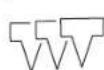
Connecting the Air Supply (see figure A)
Make sure that the pressure of the compressed-air system is below the maximum permitted rated pressure of the pneumatic tool. Firstly, set the air pressure to the lower value of the recommended rated pressure (see "Technical Data").
When in doubt, check the pressure at the air inlet with a pressure gauge with the pneumatic tool switched on.
For maximum performance, the values for the supply-air hose 13 (connection thread, maximum operating pressure, inner hose diameter, maximum hose length; see "Technical Data") must be observed.
The compressed air supplied should be free of foreign material and moisture to protect the tool from damage, contamination, and the formation of rust.
All fittings, connecting lines and hoses must be dimensioned for the pressure and the required air volume.
Avoid restrictions in the air supply, e.g., from pinching, kinking, or stretching!
Connecting the Air Supply to the Pneumatic Tool
Empty the magazine 8.
(See "Emptying the Magazine", page 26)
For the following worksteps, a fastener can be discharged when interior parts of the pneumatic tool are not in the starting position due to repairs, maintenance or transport.
- Connect the air connector 6 with a supply-air hose 13 equipped with an air-connection coupling 12.
- Check the proper function by placing the outlet 11 or the rubber workpiece protector 1 of the pneumatic tool onto a piece of scrap wood or wood material, and discharging once or twice.
Loading the Magazine (see figures B1-B2)

Disconnect the air supply before making any adjustments, changing accessories, or placing the pneumatic tool aside. This safety measure prevents accidental starting of the pneumatic tool.
Use only original Bosch accessories (see "Technical
Data"). The precision parts of the pneumatic tool such as the magazine, the outlet and the shot duct are matched to Bosch staples, nails and brads. Other manufacturers use other steel qualities and sizes.
Using fasteners not permitted, can damage the pneumatic tool and cause injuries.
While loading the magazine, hold the pneumatic tool in such a manner that the outlet 11 is not pointed at your own body or at other persons.
- Pull back the magazine slider 7 until it engages at the rear.
Note: The magazine slider must slide back with only low force (finger-pressure). A tight-running magazine slider causes the nails to be driven in at an incorrect angle.
Clean and lubricate the magazine slider 7 as required and make sure that the magazine 8 is not dirty/soiled.
- Insert a fitting nail strip 14.
Do not use nail strips with less than 5 nails. Do not insert more than 2 nail strips. Make sure that the heads of the nails do not overlap.
GSN 90-34 DK: With this pneumatic tool, a lock function of the magazine slider prevents the last nails from being discharged. Approx. 7 nails remain in the magazine.
- Completely pull back the magazine slider 7 once more to free the lock.
- Carefully guide the magazine slider to the front until it touches the nail strip.
Make sure that the magazine slider is slid beyond the head of the last nail.
Note: Do not let the magazine slider snap back without guiding it. Otherwise, the magazine slider could become damaged, and there is danger of your fingers being caught or pinched.
Operation
Actuation systems
The pneumatic tool can be operated with two different actuations systems:
- Single actuation with safety run
With this actuation system, the discharge lock-off 2 must first be firmly pressed against the workpiece. A fastener is not discharged until the trigger 10 is pulled. Afterwards, further discharging procedures can only be actuated, when the trigger and the discharge lockoff have first been set back to the starting position.
- Contact actuation
With this actuation system, the trigger 10 must be pulled first. A fastener is always discharged when the discharge lock-off 2 is firmly pressed against the workpiece while the trigger is pressed.
This enables a higher working speed to be achieved.
The actuation system is set via the selector switch 9.
Starting Operation

Disconnect the air supply before making any adjustments, changing accessories, or placing the pneumatic tool aside. This safety measure prevents accidental starting of the pneumatic tool.
Working with Single Actuation (see figure C)
- Press selector switch 9 inward and at the same time pivot it to the bottom position until it engages.

The actuation system "single actuation" is set.
- Release the selector switch 9 again.
- Firmly position the outlet 11 or the rubber workpiece protector 1 on the workpiece until discharge lock-off 2 is pressed in completely.
- Afterwards, briefly press trigger 10 and release again.
A nail is discharged. - Allow the pneumatic tool to bounce back from the workpiece.
- For another driving procedure, completely lift the pneumatic tool from the workpiece and position it firmly at the next desired location.
Working with Contact Actuation (see figure D)
- Press selector switch 9 inward and at the same time pivot it to the upper position until it engages.

The actuation system "contact actua tion" is set.
- Release the selector switch 9 again.
- Press and hold the trigger 10.
- Firmly position the outlet 11 or the rubber workpiece protector 1 on the workpiece until discharge lock-off 2 is pressed in completely.
A nail is discharged.
- Allow the pneumatic tool to bounce back from the workpiece.
- For another driving procedure, completely lift the pneumatic tool from the workpiece and position it firmly at the next desired location.
- Move the pneumatic tool uniformly over the workpiece by lifting it off and applying it again.
Each time when applying the pneumatic tool while the discharge lock-off is pressed in, a nail will be discharged.
- As soon as the desired amount of nails have been driven in, release trigger 10 again.
Working Advice

Disconnect the air supply before making any adjustments, changing accessories, or placing the pneumatic tool aside. This safety measure prevents accidental starting of the pneumatic tool.
Check the proper function of the safety and actuation devices, and the tight seating of all screws and nuts each time before using.
Disconnect a defective or not properly operating pneumatic tool immediately from of the air supply and contact an authorised service agent for Bosch power tools.
Do not perform any incorrect manipulations on the pneumatic tool. Do not disassemble or block any components of the pneumatic tool, such as the discharge lock-off.
Do not carry out "emergency repairs" with unsuitable means. The pneumatic tool is to be maintained regularly and properly (see "Maintenance and Cleaning", page 27).
26 | English
Avoid any weakening and damage whatsoever of the pneumatic tool, e.g., through:
- Imprinting or engraving,
Retrofitting measures not approved by the manufacturer,
-Guidingalong templates m al,e.g.steel, - Dropping on or sliding over the floor,
Using as a hammer,
Applying any kind of force.
Make sure to check whatever is below or behind your workpiece. Do not shoot nails into walls, ceilings or floors, when persons are behind them. The nails can burst through the workpiece and injure someone.
Do not shoot a nail onto an already driven-in one. This could cause the nail to deform, the nails could become jammed or the pneumatic tool could move uncontrolled.
When the pneumatic tool is used under cold ambient conditions, the first nails will be driven in slower than usual. Once the pneumatic tool has warmed up during working, normal operating speed will be regained.
Avoid blank shots in order to reduce the wear of the impact striker.
For longer work breaks or after finishing work, disconnect the pneumatic tool from the air supply and empty the magazine.
Emptying the Magazine
Pull back the magazine slider 7 until it engages at the rear.
- Remove the nail strips 14.
Discard nail strips with less than 5 nails.
- Completely pull back the magazine slider 7 once more to free the lock.
- Carefully guide the magazine slider to the front until it touches the beginning of the magazine.
Note: Do not let the magazine slider snap back without guiding it. Otherwise, the magazine slider could become damaged, and there is danger of your fingers being caught or pinched.
Adjusting the Depth Stop (see figure E)
The driving depth of the nails can be set with depth stop 3.
- Empty the magazine 8.
(See "Emptying the Magazine", page 26)
- To reduce the driving depth, turn the depth stop clockwise.
or
To increase the driving depth, turn the depth stop anticlockwise.
- Refill the magazine.
(See "Loading the Magazine", page 24) - Test the new driving depth on a test workpiece.
a Repeacthebwofoksskneqquired.
Clearing Jams (see figures F1-F3)
Single nails can become jammed in the shot duct. If this should occur frequently, please contact an authorised service agent for Bosch power tools.
- Empty the magazine 8.
(See "Emptying the Magazine", page 26) - Open the magazine lock 15.
Pull the magazine 8 away from the housing until it slips off of lock pin 16.
This makes the jammed nail in the shot duct accessible.
- Remove the jammed nail. For this, us a pair of pliers, if required.
- When driver blade 17 is extended, push it back into the piston using a lubricated screwdriver or other suitable lubricated object.
Lubricate the shot duct with 2-3 drops of engine oil (SAE 10 or SAE 20). - Reinsert the magazine 8 again:
Open the magazine lock 15, if required. Guide lock pin 16 into the opening of magazine holder 18. Align the magazine to magazine retainers 19 and push the magazine completely to the front. Lock the magazine by completely folding magazine lock 15 up.
- Refill the magazine.
(See "Loading the Magazine", page 24)
Changing a Magazine Rail (see figure G)
The magazine rails 20 can wear after prolonged use of the pneumatic tool.
Replace defective magazine rails.
- Empty the magazine 8.
(See "Emptying the Magazine", page 26) - Loosen locking screw 21 (3 mm) with the supplied Allen key.
Pull cover lid 22 out of the magazine 8 - Allow the defective magazine rails 20 to slide out of the magazine.
- Insert new magazine rails into the magazine.
- Insert cover lid 22 back into the magazine and tighten locking screw 21.
Changing the Workpiece Protector (see figure H)
The workpiece protector 1 at the end of the discharge lock-off 2 protects the workpiece until the pneumatic tool is correctly placed for the driving procedure.
The workpiece protector can be removed and replaced.
- Remove spring clip 23 and pull the workpiece protector from the discharge lock-off 2.
- Push the new workpiece protector over the discharge lock-off and mount the spring clip again.
Stationary Use of the Pneumatic Tool (see figure I)
For stationary use, the pneumatic tool can be fastened to a balancer.
The screwable eyelet 24 is required for this.
- Remove the rear screw of the exhaust cap with the supplied Allen key.
Screw the eyelet 24 firmly into the exhaust cap. - Hook the eyelet to the balancer hook.
Transport and Storage
For transport, disconnect the pneumatic tool from the air supply; especially when using ladders or moving in an unusual stance or posture.
At the workplace, carry the pneumatic tool only by the handle 5 and with the trigger 10 released.
Always store the pneumatic tool disconnected from the air supply and at a clean and dry location.
When not using the pneumatic tool for a longer period of time, cover steel parts with a fine oil coating. This prevents the formation of rust.
Maintenance and Service
Maintenance and Cleaning

Disconnect the air supply before making any adjustments, changing accessories, or placing the pneumatic tool aside. This safety measure prevents accidental starting of the pneumatic tool.
If the pneumatic tool should fail despite the care taken in manufacture and testing, repair should be carried out by an authorised customer services agent for Bosch power tools.
In all correspondence and spare parts orders, please always include the 10-digit article number given on the type plate of the pneumatic tool.
Have maintenance and repair work carried out only through qualified persons. This will ensure that the safety of the pneumatic tool is maintained.
An authorized Bosch after-sales service agent will carry out this work quickly and reliably.
Lubricating the Pneumatic Tool (see figure J)
When the pneumatic tool is not connected to a maintenance unit, it must be lubricated at regular intervals:
- F or light-duty use 1x per day.
- F or heavy-duty use 2x per day.
Apply 2-3 drops of lubricant into air connector 6. Do not apply too much lubricant, which could then accumulate in the pneumatic tool and be emitted via air outlet 4.
Use only the lubricants recommended by Bosch.
SAE 10 mineral engine oil (for use at very cold ambient conditions)
SAE 20 mineral engine oil
Observe all applicable environmental regulations when disposing of old grease and solvents.
28 | English
Maintenance Schedule
Always keep air outlet 4, discharge lock-off 2 and trigger 10 clean and free of foreign material (dust, chips, sand, etc).
Clean the magazine 8. Remove any plastic or wood chips that may accumulate in the magazine during operation.
Clean the pneumatic tool in regular intervals using compressed air.
| Measure Explanation Action | ||
| Draining the exhaust filter daily. | Prevents the accumulation of dirt/ debris and moisture in the pneumatic tool. | - Open the drain valve. |
| Keeping the lubricator filled at all times. | Ensures the lubrication of the pneumatic tool. | -Fill lubricator with the recommended lubricants.(See "Lubricating the Pneumatic Tool", page 27) |
| Cleaning the magazine 8 and maga-zine slider 7. | Prevents the jamming of nails. - Blow out the mechanism of the magazine/magazine slider daily with compressed air. | |
| Ensuring that the discharge lock-off 2 functions properly. | Promotes your work safety and effi-cient usage of the pneumatic tool. | - Blow out the mechanism of the discharge lock-off daily with com-pressed air. |
| Lubricating the pneumatic tool. | Reduces the wear of the pneumatic tool. | -A p I y 2-3 drops of lubricant into air connector 6.(See "Lubricating the Pneumatic Tool", page 27) |
| Draining the compressor. Prevents the accumulation of dirt/ debris and moisture in the pneumatic tool. | - Open the drain valve of the compressor tank. | |
Correction of Malfunctions
| Problem Cause Corrective Measure | ||
| The pneumatic tool is ready for operation but no nails are dis-charged. | A nail is jammed in the shot duct. - Clear the jam.(See "Clearing Jams", page 26) | |
| The magazine slider is 7 defective. | - Clean and lubricate the magazine slider 7 as required and make sure that the magazine 8 is not dirty/soiled. | |
| The spring of the magazine slider is too week or defective. | - Contact an authorised service agent for Bosch power tools.Have the component replaced there. | |
| The fasteners being used are not permitted. | - Use only original accessories.Only the fasteners (nails, staples, etc.) specified in table "Technical Data" may be used. | |
| The magazine 8 is empty. - Refill the magazine.(See "Loading the Magazine", page 24) | ||
| The nails are discharged very slowly and with too little pres-sure. | The rated pressure of the compressed-air supply is too low. | - Increase the compressed-air supply.8 bar may not be exceeded. |
| The driver blade is damaged. - Use only the lubricants recommended by Bosch.(See "Lubricating the Pneumatic Tool", page 27) | ||
| The sealing ring of the piston is worn or damaged. | - Contact an authorised service agent for Bosch power tools.Have the component replaced there. | |
| The buffer is worn. - Contact an authorised service agent for Bosch power tools.Have the component replaced there. | ||
| The length and diameter of supply-air hose 13 do not correspond with the data of this pneumatic tool. | - Use a supply-air hose with the correct dimensions.(See "Technical Data", page 23) | |
| The supply-air hose 13 is bent/creased. | - Correct the bend/crease in the supply-air hose. | |
| The nails are driven in too deep. | The rated pressure of the compressed-air supply is too high. | - Reduce the compressed-air supply.4 bar may not be fallen below. |
| The depth stop is set too deep. | - Adjust the depth stop to the desired depth.(See "Adjusting the Depth Stop", page 26) | |
| The buffer is worn. - Contact an authorised service agent for Bosch power tools.Have the component replaced there. | ||
30 | English
Problem Cause Corrective Measure
| The nails are not driven in deep enough. | The rated pressure of the compressed-air supply is too low. | - Increase the compressed-air supply. 8 bar may not be exceeded. |
| The depth stop is set too high. - Adjust the depth stop to the desired depth.(See "Adjusting the Depth Stop", page 26) | ||
| The length and diameter of supply-air hose 13 do not correspond with the data of this pneumatic tool. | - Use a supply-air hose with the correct dimensions.(See "Technical Data", page 23) | |
| The supply-air hose 13 is bent/creased. | - Correct the bend/crease in the supply-air hose. | |
| The pneumatic tool skips nails or has a too large cycle feed. | The fasteners being used are not permitted. | - Use only original accessories. Only the fasteners (nails, staples, etc.) specified in table "Technical Data" may be used. |
| The magazine 8 is not operating correctly. | - Clean and lubricate the magazine slider 7 as required and make sure that the magazine 8 is not dirty/soiled. | |
| The spring of the magazine slider is too week or defective. | - Contact an authorised service agent for Bosch power tools. Have the component replaced there. | |
| The sealing ring of the piston is worn or damaged. | - Contact an authorised service agent for Bosch power tools. Have the component replaced there. | |
| Frequent jamming of nails in the shot duct. | The fasteners being used are not permitted. | - Use only original accessories. Only the fasteners (nails, staples, etc.) specified in table "Technical Data" may be used. |
| - Contact an authorised service agent for Bosch power tools. | ||
| The driven nails are bent. | The driver blade is damaged. | - Contact an authorised service agent for Bosch power tools. Have the component replaced there. |
| Contrary to working with normal operating speed, the nails are not driven in deep enough at higher operating speed. | The interior diameter of the supply-air hose is too low. | - Use a supply-air hose with the correct dimensions.(See "Technical Data", page 23) |
| The compressor is not suitable for fast operating speeds. | - Use a compressor that is sufficiently dimensioned for the number of connect- ed pneumatic tools and the operating speed. | |
English | 31
Accessories
For more information on the complete quality accessories program, please refer to the Internet under www.bosch-pt.com or contact your specialist shop.
After-sales Service and Customer Assistance
Our after-sales service responds to your questions concerning maintenance and repair of your product as well as spare parts. Exploded views and information on spare parts can also be found under:
www.bosch-pt.com
Our customer service representatives can answer your questions concerning possible applications and adjustment of products and accessories.
Great Britain
Robert Bosch Ltd. (B.S.C.)
P.O.Box 98
Broadwater Park
North Orbital Road
Denham
Uxbridge
UB95HJ
Tel. Service: +44 (0844) 736 0109
Fax:+440844)7360146
E-Mail: boschservicecentre@bosch.com
Ireland
Origo Ltd.
Unit 23 Magna Drive
Magna Business Park
City West
Dublin 24
Tel. Service: +353 (01) 466 67 00
Fax: +353 (01) 466 68 88
Australia, New Zealand and Pacific Islands
Robert Bosch Australia Pty. Ltd.
Power Tools
Locked Bag 66
Clayton South VIC 3169
Customer Contact Center
Inside Australia:
Phone: +61 (01300) 307 044
Fax: +61 (01300) 307 045
Inside New Zealand:
Phone: +64 (0800) 543 353
Fax:+64(0800)428570
Outside AU and NZ:
Phone: +61 (03) 9541 5555
www.bosch.com.au
Republic of South Africa
Customer service
Hotline: +27 (011) 6519600
Gauteng - BSC Service Centre
35 Roper Street, New Centre
Johannesburg
Tel.: +27 (011) 4 93 93 75
Fax: +27 (011) 4930126
E-Mail: bsctools@icon.co.za
KZN - BSC Service Centre
Unit E, Almar Centre
143 Crompton Street
Pinetown
Tel.: +27 (031) 701 21 20
Fax: +27 (031) 7 01 24 46
E-Mail: bsc.dur@za.bosch.com
Western Cape - BSC Service Centre
Democracy Way, Prosperity Park
Milnerton
Tel.: +27 (021) 5512577
Fax: +27 (021) 5513223
E-Mail: bsc@zsd.co.za
Bosch Headquarters
Midrand, Gauteng
Tel.: +27 (011) 6519600
Fax: +27 (011) 6519880
E-Mail: rbsa-hq.pts@za.bosch.com
Disposal
The pneumatic tool, accessories and packaging should be sorted for environmental-friendly recycling.
When your unit is no longer suitable for use, please return it to a specialist store or send it directly (sufficiently post-paid please) to:
The units will be disassembled. Plastics, e.g., the housing which are primarily made of polyamide, are identified
(Bosch detection code for plastics since 1992) and recycled. Iron, steel, aluminium and cast parts are melted in a high-temperature furnace and recycled. Copper scrap is shredded (without heat) and returned to the copper industry as copper granulate.
Subject to change without notice.


Dr. Egbert Schneider Senior Vice President Engineering
Dr. Eckerhard Strotgen
Head of Product Certification
ppa. 1
Robert Bosch GmbH, Power Tools Division
D-70745 Leinfelden-Echterdingen
Leinfelden, 08.12.2009
Montage
Robert Bosch (France) S.A.S.
Sousreservedemodifications.
Senior Vice President
Head of Product
Engineering
Certification
ppa. Me H
Robert Bosch GmbH, Power Tools Division
D-70745 Leinfelden-Echterdingen
Leinfelden, 08.12.2009
Montaje
Senior Vice President
Engineering
Dr. Eckerhard Strötgen
Head of Product
Certification
Paa.
Robert Bosch GmbH, Power Tools Division
D-70745 Leinfelden-Echterdingen
Leinfelden, 08.12.2009
Montagem
Senior Vice President
Head of Product
Engineering
Certification
Paa.
Robert Bosch GmbH, Power Tools Division
D-70745 Leinfelden-Echterdingen
Leinfelden, 08.12.2009
Montaggio
Dr. Egbert Schneider Senior Vice President Engineering
Dr. Eckerhard Strotgen
Head of Product Certification
ppa.
Robert Bosch GmbH, Power Tools Division
D-70745 Leinfelden-Echterdingen
Leinfelden, 08.12.2009
Montage
Dr. Egbert Schneider Senior Vice President Engineering
Dr. Eckerhard Strotgen
Head of Product Certification
paa /nae i.v. nuo:
Robert Bosch GmbH, Power Tools Division D-70745 Leinfelden-Echterdingen Leinfelden, 08.12.2009
Montering
Tilslutning til luftforsyningen (se Fig. A)
Bosch Service Center
Telegrafvej 3
2750 Ballerup
Tel. Service Center: +45 (4489) 8855
Fax: +45 (4489) 87 55
E-Mail: vaerktoej@dk.bosch.com
Dr. Egbert Schneider Senior Vice President Engineering
Dr. Eckerhard Strotgen
Head of Product Certification
Paa
Robert Bosch GmbH, Power Tools Division
D-70745 Leinfelden-Echterdingen
Leinfelden, 08.12.2009
Montage
Bosch Service Center
Telegrafvej 3
2750 Ballerup
Danmark
Tel.: +46 (020) 41 44 55
Fax: +46 (011) 187691
Avfallshantering
Dr. Egbert Schneider Senior Vice President Engineering
Dr. Eckerhard Strotgen
Head of Product Certification
ppa. 1
Robert Bosch GmbH, Power Tools Division
D-70745 Leinfelden-Echterdingen
Leinfelden, 08.12.2009
Montering
Dr. Egbert Schneider Senior Vice President Engineering
Dr. Eckerhard Strotgen
Head of Product Certification
Pp. 110
Robert Bosch GmbH, Power Tools Division D-70745 Leinfelden-Echterdingen Leinfelden, 08.12.2009
Asennus
Senior Vice President
Head of Product
Engineering
Certification
P_1Q = 12L
Robert Bosch GmbH, Power Tools Division
D-70745 Leinfelden-Echterdingen
Leinfelden, 08.12.2009
Συναρμολόγηση
Suvtnpnon kal Service
Dr. Egbert Schneider
Senior Vice President Engineering
Dr. Eckerhard Strotgen
Head of Product Certification
ppa. 1
Robert Bosch GmbH, Power Tools Division
D-70745 Leinfelden-Echterdingen
Leinfelden, 08.12.2009
Montaj
Hava ikmalinin baglanmasi (Bakiniz: Sekil A)
Bosch San. ve Tic. A.S.
Ahi Evran Cad. No:1 Kat:22
Polaris Plaza
80670 Maslak/Istanbul
Müsteri Danismani: +90 (0212) 335 06 66
Müsteri Servis Hatti: +90 (0212) 335 07 52
Dr. Egbert Schneider Senior Vice President Engineering
Dr. Eckerhard Strotgen
Head of Product Certification
ppa. 1
Robert Bosch GmbH, Power Tools Division
D-70745 Leinfelden-Echterdingen
Leinfelden, 08.12.2009
Montaž
Robert Bosch Sp. z o.o.
Senior Vice President
Head of Product
Engineering
Certification
Paa.
Robert Bosch GmbH, Power Tools Division D-70745 Leinfelden-Echterdingen
Leinfelden, 08.12.2009
Montáz
Pripojeni na zdroj vzduchu (viz obr. A)
Bosch Service Center PT
K Vapence 1621/16
692 01 Mikulov
Tel.: +420 (519) 305 700
Fax: +420 (519) 305 705
E-Mail: servis.naradi@cz.bosch.com
www.bosch.cz
Zprcovani odpadu
Senior Vice President Engineering
Dr. Eckerhard Strötgen
Head of Product
Certification
paa / 134 i.v. nuo7ycu
Robert Bosch GmbH, Power Tools Division
D-70745 Leinfelden-Echterdingen
Leinfelden, 08.12.2009
Montáž
Senior Vice President
Head of Product
Engineering
Certification
ppa. 1
Robert Bosch GmbH, Power Tools Division
D-70745 Leinfelden-Echterdingen
Leinfelden, 08.12.2009
Összeszerelés
IpoaHTaTe N yuHTbBaTe BCE
yKa3aHHa. KaCaeACTBne
HecobOeHn CyeUx yka3aHH TcHexnke 6e0tacHOCTN BO3MOXhI TOpaxHe Hne 3AekTpuecknM TOKOM, ONaCHOCTb BO3HKNHOBeHn POkapa NAn TAgKeAbix TpaBM.
TuaTeAboHo coxpaHnTe 3TH HnCTpyKuHn T0 6e3oNaCHOCTH.
1) Be3oTachoctb pa6oeryo MecTa
a)CoAePKeIte BaIe pa6ooye MeTo B uHcTote H XopoOIOOCBeUeHHbIM. BecnopraOK Ha pa6ooyem MecTe H HeocBueeHHbIe yHaCTKn pa6oTbI MoryT PnBecTH K HeCuaCTHbIM CAYaAM.
6)He pa6oTaTe C THEBMOnHCTpyMeHTOM BO B3pbIBOOITACOM TOMEueHH, B KOTOPOM HxOaTcR TOpOHne XnAkoCTH, Ra3bI HAN TbIAb. Pn 6pa6oTKe AeTaH N Bo3MOXHO Bo3HNKHOBeHne INCKP, KOToBpIe BeAyt K BOCIIaMeHeHIO TbAIH HApOB.
B)Пи pa6ote c ПHEBMOnHcTpymeHtOM He AOnyckaIte 6An3ko K BaWemy pa6oey My MecTy AIO6ObIbTHbIX, DeTe H IOCTOpOHnX Anu. 3TN Anua MOrY OTBaueb BaWe BHNMaHne N Bi IOTepReTe KOHTPOAb HaI PHEBMOnHcTpymeHtOM.
2) Be3oTnachOCTb THeBMaTHueCKHX HnCtpmEHTOB
a)Ппмение сахын BO3aYx 5- ro Klaacca KauecTba
ПО ДИН ИСО 8573-1 ИнДИВДАуаьнblу 6ANO
BO3aYxOToAroTOBKN B6AN3n ПЕBMOnHCTpyMeHTa.
Aa3aunbTTIHEBMOnHCTpyMeHTaOTIOBpeXeHH, 3aqrpa3HeHHN IO6pa3oBaHHN Koppo3nn IooaBaembl CxTaBn BO3dyX DOJKeH 6bITb OUnuE H OT IOCTOpOHHNX YacTn H BAAH.
6)Побергп Te PnHcOeMHHeHH N AHHN INTahHH.
Bce 6aOKn Bo3dYxIOaRoTObKN, MyΦTbI H IaHrN DoJXhbl 6bItb paccuHTaHb Ha DaBHeHne I paCXoD Bo3dYxa corAcho TexHueckm DaHHbIM. Hn3Koe DaBHeHne OtpuaTeAho BAnreT Ha FyHKuHO THeBMOnHCTpyMeHTa, 3aBbIeHHO daBHeHne MoKet TpNBecn K TOBpeXdEHNM I TpaBMam.
B)3aunuane WAAHnOT NpeRn6OB, NpepKHMOB, pactbOpHTeAeH NoctpbIX KpOMok. 3aunuane TWAaHn OT BO3dEChTBNA IOBbIWeHHbIX TEMepaTp, Mcna H BpaauoUxxC AetAeH. HeMeDAeHHO 3aMeHnTe IOBpeXDeHHbI WAAHR.
fekTHa HHHH INHTAHN MOXeT PnHBecTN K 6bIouMeMy BOKpyr ce6y IHaHry CxKaTOro BO3Dyxa H CTaTB PPuHHOITpaBM. POAnHTaB B03DyX PbIb HAN CTpykKa MOXeT Bb3BaTb TKeAble TpaBMbl Ia3.
r) CλeAHTe 3a Tem, yTo6bI xOMyTHKn ⅢaHroB 6bln Bcerda KpeKNo 3aTAYtbl. Cλa6o 3akpeNHe Hnn TOBpeXeHHbe XOMYTHKn ⅢaHra Moγr CTaTb πpUHoh yTeuKn BO3dya.x.
3)Be3oTnacHocTb AIOAeI
a)6ydbTe BHNMaTeAeBbIMn, CLEdnte 3a TeM, qTo BbI Deaaete N IPOdymaHNO HauHHaTe pa6Oty C THeBMOnHCTpyMeHtOM. He IOa3yIteCb THeBMOnHCTpyMeHtOM B yCTaON COCToHHN HAN, ecAn Bbl HaxoHTecb NOA BANHHem HAPKOTKOB, CTnPTbIX HAnNTKOH AN AekapCTB. OAHN MOMENT HeBHmAteAeBOcTH INp PA6Ote C THeBMOnHCTpyMeHtOM MOXET PnHBecTNI K cepBe3HbIM TpaBMam.
6)Ппмени TE HANBHAyaHbHbe CpeCTBa 3aunTb IN Bcerda 3auNThble ouKn. Ппmehene CpeCTB INHnBHyAaHOB 3auNTbI, KaK To TbIe3aHTHO peCINHpataTopa, cTeOObyBn, 3auHTHO rIeMa, CpeCTB 3auNTbI OpraHOB CAYxa, B 3aBNCMocTH OT BHa n YcAoBN pa60Tb C IHeBMOnHCTpyMeHTOM, CHNkaet pnc TpaBMnpoBAHn.
B)ПпeТОТВРаше He npeHnAmepeHnE BKIOUOeHne. Пepe IIOKIAIOUeHem THeBMOHCTpyMeHTa K BO3dYxOCH6KeHHIO, TepeTeM, KaK BbI Bo3bMeTe erO BpyKN TpAHCIOPTHPOBkoI PpOBepbTe erO BbIKAOUeHHO COCTOJHNe. YdePkaHne NaIbua Ha BbIKAOUaTeI PrN TepeHOce THeBMOHCTpyMeHTa HIN IOKIAIOUeHne BKIAIOUeHHoro THeBMOHCTpyMeHTa K NcTOuHHky BO3dYxa YpeBaTo HecuactHBIM CAYaAMN.
r)IpeA BKAIOUeHHem THeBMOHcTpymeHa y6epHTe YctaHOBOuHbI INcTpymeHT, YCTaHOBOuHbI INcTpymeHT,HXoAaHmCBA BpaAooJIeC4 aCtN THeBMOHcTpymeHa, MoKet IpNBecn K TpaBMam.
A)He nepeoueHHBaTe ce6B.Bcerda 3aHHMaHte yToHnBOe TIOAOKeHne H BcERDa BbIePxHBaTe paBHObecHe. YToHnBOe TIOAOKeHne H COOTBeCTByIOOee TIOAOKeHne KOpTyCa TIO3BOAT Bam AuyWe CTPaBHTbcrC THeBMOnHCTpyMeHtOM B HeoxNHaH HbIX CNTyauNX.
e)HocHTe noxoadyIO oExy.He HocHTe 1npokyo OExyHy ykpaeeHH. AepKHTe BOACbI, oExy H nepaATKn B CTOPHe OT ABHXyUHXc qacte. 山pOKaOexKa, ykpaeeHH Nn DAnHHbE BOACbI MOrTy 6bTb 3aTReHYbBpaAiooUMNCH qactmN.
K)IIpH HAAHNN BO3MOXHOCTN yCTAHOBKN TbIAEOTcABIBAOUHX N TBIaec6OpBHX yCTPOHCTB IPOBepnE Hx INPHCOeAHHEHHe N IpaBnAbHoE NCIOABoHHe. HCIOABoHHe 3THX yCTPOHCTB CHNXaET OTACHOCTb OT BO3DeCTBnTbIaH.
3) He BbIXaIte OTPa6oTaHHb BO3dYx. CaeHnte 3a TEM, UTO6bI OTPa6oTaHHb BO3dYx He IOTaDaA B rA3a. OTPa6oTaHHb BO3dYx N3 THEBMOnHCTpyMeHTa MOKeT COePxaTb BOy, MaCIO, MetaAnueckne YactnU b 3aPrz3HeHn, IOTaJaIoUHe n3 KOMPipeccOpa. 3To MoKeT HmEtB BpeDHOE BANHHe Ha 3OpOBBe.
4)TuataeAbhoe 06xoxdHeHc THeBMOHCTpyMeHTAMN HNX PpABAbHoe PpMHeHHe
a)Дуdepкнвани ИОпоры DeTaIиПь3yTeCb 3aXHMbIMN yCTPOHCTBaMn HAN THCKAMN. YdepKIBaIeTaIb pyKoI IIN IIpiXmHa ee K TeY, Bbl He moKete HaexHo yIpaBArTb THeBMOnHCTpyMeHTOM.
6)He neperpkaTe THeBMOnHcTpymeHT. HcnoB3yIte DaBaWe pa6oTbI IpeHa3HaueHHbI DA 3TOI THeBMOnHcTpymeHT.C IOxOaIIM THeBMOnHcTpymeHTOM Bbl pa6oTaete Ayuwe HaedKHee ByKa3aHHOM dHaPa3oHe MOUHOCTN.
B)HeNoAbyItebTheBMOnHcTpymeHtOM C HeNCTpabBbIM BblKIOUaTeAeM. TheBMOn HcTpyMeHT, KOToBn He NoDAaeTCBkIOueHIO IAN BblKIOueHIO, OtaCeH IOAKeH 6bITb OTpeMOHTnpoBaH.
r) OTKIouaTe IODaCy CxAToRo BO3DyXa Do HaaAHaHAcTPOKn HcHTpymeHTa, CMeHbIOChAcTk HnIpeXde Yem BbITyCTHTb THEBMOnHcTpymert H3pyk. 3Ta Mepa IIpeOCTOpOXHocTH INpeOTBpaaaet HeIIpeDAHamepeHHbI Tysck IHeBMOnHcTpymEHTa.
A)XpaHHTe HEnCTOaB3yeMbIe THeBMOnHCTpyMeHtBI HeDocraEOM AAn DeTeM Mecte. He pa3pewaIte IOnb3OBaTbCnTHEBMOHNCTpyMeHToM Anuam, KOtOpbIe He3HaKOMbl C Hm Nn Hne YHTaAN HactoAunx HnCTpyKnn. THeBMOnHCTpyMeHtBI OtnaChbl B pyKaX HeONbITbIX Anu.
e)TuaTeNbHO yxaXHBaIte 3a THeBMOHcTpymeHTOM. PIOBepaIte 6e3yIpeHyo yHKuHIO xOa ABHXUHXcAucteN THeBMOHcTpymeHTa, OTCYCTBnE ITOAMOK Hn IOBpeKdEHn, OTPuaTeNbHO BAHAIOxH Ha yHKUHO THeBMOH
ctpyMeHa. TOBpeXeHHeBie qactn DOxKbI b6Itb OTpEmOHtpoBaHbI dIOCTOa3OBaHHr THeBMOnHcTpyMeHa. Ioxoe o6CayKbAHne IIHeBMOnHcTpMyeHTOB RABaETcPnUHHo 6oABoTOO uCAa HecuACThIx CAYaEB.
K)IIpHMeHnTe IHeBMOHNcTpymeHT,IIpHnHaA AExKnctn,pa6Oue HNcTpymeHTbI N T.I.B COOTBeTcBn C HAcToaUMN HNcTpkyuHAMn. YuHTbIBaTe IIpn 3tOM yCAOBn H BnPa60tbl.
NcnoB3OBaHHe INHEBMOnHCTpyMeHTA DAn APyRnx, HnpeDyCMToPeHHbIX paOTo MOKeT npNBecTu K ONaCHbIM CNTyaunm.
5) CepBnC
a) Pemont Baawero INheBMOHnCTpyMeHTA TOpuyaTe TObKO KBAAnHnUPOBAHOMY TepcoHany I TObKO C HTOA3OBAHHeM OPHINHaABhBX 3aTuaCTeN. 3THM 06ecneHbAETC863oNaCHOCTb INHEBMOnHCTpyMeHTA B DaAbHeHWeM.
YKa3aHnI IO TexHKe 6e3oNaCHOCT DAJI THeBMaTHuecknx CkO6o- I rBO3e3a6NBbIX HHCTpyMeHTOB

Hcnoab3yIte 3aunTHbIe OuyKn.
Bcerda hxCOAnTe H3 TORO,TOB THeBMOnHCTpymEnTe HaxoANTc KpeTExHH MaTePhA. He6peXHoe 6paueHne C THeBMOnHCTpymEnTom MOxET PnBecTN K HeoKHaHHOMy BbTaAaKbAHIO KpeTExHoro MaTePhAa, BCAeCTBne Yero Bbl Moxete IToAuyntb TpaBMbl.
AepxHTE INHEBMONHcTpMeHT BO Bpempa60tbI Tak, 106bI Bbl He MOrAn IopaHnTB roLoBy H TeAo PnB03MOXHOM PNKOWeTe BCAECTBHe HEnCIIpaBHocTeB C cTH NITAHN HAN HATAKKBHNA HHCtPymeHTa Ha TBepAbie MeCTa B 3aROTOBKe.
He HappaBnIe THeBMOHnHcPymEt Ha ce6n APyrHx IIOeH, HaxoAunXncr N6bN3OCTN. BcAeCTBne HeoxnHaHHoro Tpycka HnHcTpmyEHTa BblTaAKNBaetc KpeTKeHHbIM MaTePha, YTO MoKet TpNBecTn K TpaBMam.
He BkIoUaIe TnHEBMOnHcTpymENT, noka Bbl He TpncTabHAn erO IpoUHO K3arToBKe. EcaM MeKdY THeBMOnHcTpymEHTOM H 3arOTOBKOH eT KOHTa, KpeTeXhBi MaTeHnMoKet OTCKOHTb OT MecTa KpeTHeHHN H TpNBecTH K TepeRpy3Ke THeBMOnHcTpymEHTa.
218|Pycckn

He pa6oTaIe Ha AeCTHuaX HAn IIOMoctax,
ecAN BKAIOueHa CnCTema CnTycka
KoHTaKTbI b CTyck.B YacTHocTH,
3aTpeaaetc TpeMeuaTbcra H NOMocTAX,
AeCTHuaX, CTpeMaHKx HAn IOdo6bIX
KoNCTpykunx, KaK HAp., 06peWetkax
KpbU,OT OAnHO MeCTa pa6oTbIK Apyromy,
3aKpbBaTb IuNKn HAn IpeperOpOaKN HAn
OChauTb, HAp., TpaHCnToPThbIe CpeCtBa
HAn BaHObl, TpaHCnToPThbIMNΦHKCaTopaMn.
ECAn BBy II pRi 3TOI CNCTe M CnYCa C LyuahHO
IIpNCtABITE INHeBMOnHCTpyMeNT K 3aROTOBKe
IIpN HAKaTOM PpeOxoPaHnte CeNCKOBOrO
KpOka, KaKDb pa3 6yDeT BItaKaKNBaTbcr
KpeTeKbH MaTePhaA. 3TO MoKET IpnBeCTN K
TpBaMam.
CaeIeHTe 3a ycAoBnHm Ha MeCTe pa6oTb. KpeIeXhbl MaTePnaAM MoKet Ipo6uBaTb ToHKe 3aToTOBKn HnPi pa6oTaX Ha yraax N KpaX 3aToTOBOK OTCKaKNBaTb pIKoWeTOM n paHtB AIOeN.

OTKIOUHTe cHa6KeHHe BO3DyXa,ecAM KpeTeKHB MaTePna 3actpA B THeBMOHNcTpymente. ECAH
THEBMONHCTpymEHIOKAIOueH K HCTOUYKNYIHTAHN, Pn ydaenHH 3actpRBweroKpeTExHO MaTePnaA OH MOKeT 6bITBCaYauHaNO pNBBeH B DeINCTBHe.
6yDbTe ocToPOXHbI pN BbITraRbAHHH 3actpABWero KpeTExHO MaepHaA. CnCTema MoKet HaxoAnTBcH Ha B3BOe H KpeTExHbIMaepHaAMoKet 6bITb BBTOAKHyT C CnAo, KOrDa Bbl 6yDte Ipo6oBaTb BBtAunTb erO.
He hCIOb3yIe 3OT THeBMOHcTpymEn DAa 3akpeHaeHHaekTPOPiPoBOaKn. OH He PteHa3HaueH Aa PpOKaAKn 3AekTPOPiPoBOaKn, MoKet IIOBpeNTb H3oAunO 3AekTPOkaBeaN I PpNBecTN K 3AekTpueckOMy ydpy N OtnacHOth ToXkapa.
HnKorda He HcTIOa3yIe KHCLOPOd HAN TROPUOHe Ra3bI B KaueCTBe HCTOCHNKA 3HEPRHN DAITHEBMONHCTpyMeHTA. TOpUOHe ra3bI ONaChbl, OHN MOryt CTaTb PpUHHoB B3pbIbTa THEBMOHnCTpyMeHTa.
PIMHeTc COOBETCTBouHne MeTAANCKaTeA Hn HaxoXdEHHN CKpbItbIX CnCTEm 3eKtPo-,ra30-N BOOCh6KeHH Nn ObaaauTEcb 3a CnPaBkoB MEcTHoe PpEITPNrTHe KOMMyHaBHorO CH6KeHH.
KohtaKTc 3AeKtpoPBOAOKOJ MOKeT PnBecTH K Toxapy N IopaxeHNO 3AeKtpOTOKOM. TOBpeXdHne ra30IPOBOAo MoKeT PnBecTH K B3pbBy.
TObpeKdHHe BOOpPOBOa BeTe K HaHeceHIO MaTePnaAhhoro yuep6a.
IIOAKUaHTe THeBMOnHCTpymEt TObKO K Tpy6oTPOBOaM, B KOToPbIX MAcCHMaAusbHO AOITyCTHMoe AIA THeBMOnHCTpymEtA DaBaeHne He MoXeT 6bITb IpeBbIweHo 6oAee cem Ha 10%; Iprn 6OaIeM DaBaeHmN Tpy6oTPOBa CkAToR O3dYxa Heo6xOaHMo OChACTHTb peryAToPOM DaBaeHn (peyKuONHHbIM KlaTahOM) N KaTahOM ORpaHnueHn DaBaeHn. 3aBbIweHoe DaBaeHne MoXeT CTaTB IpiuHcN C6oEB B pa6ote HN IOBpeXeHn THeBMOnHCTpymEtA, YTO MOXeT IpnBeCTN K TpaBMam.
Ottncahne yHKcnn

IpouHTte Bce yka3aHn HnHCTpyKunn To texHnke 6e3oNaChocTH. YnyueHnB OTHOWeHHy kA3aHn HnHCTpyKunn To texHnke 6e3oNaChocTH MOrY CTaTB pNpuHnO npaKeHHa 3eKTPnueeckm TOKOM, POnkapa n TReKeBx TpaBM.
PnmuHeHne To Ha3HaueHHIO
THEBMONHCTpymEnTpeHa3HaueH DA COeHNHeHHA 3AEMENTBIPN KPOBeAbhIX pa60tax,o6wnbke DOCKaMn CtponTeABCTBE OpeWeToK,a TaKxE PpN H3ROTOBAAEHN CTehhX/KPOBeAbhIX 3AEMENTOB,depeBAnHbIX paacAOB, TAAET,DepeBANHbIX 3abOpOB,3ByKOn3OAnHOHHbIX CTEN RNIKOB.
Pa3peaetcNtIOb3OBaTbTObKO KpeTeXHbIMATEpHaI (rBO3n,CKo6bI N T.D.,yKa3aHHbIB Ta5nue《TexHnueckne DaHHbe》.
H306paXeHHbIe coCTaBbIe qactn
HymepaunI PpeCTaBHeHHbIX KOMIOHEHTOB BblIOAHeHa ITO H3O6paXeHNIO THeBMOnHcTpMyeHTa Ha cTpaHnue C HAIOCTpaUNAMN.
1 Pe3HOBbI KOaYOK
2 PpeoopaHnteB cnyckOBOr KpOuKa
3OrpaHnHnTeA bTaybHbI
4OTBepTneAABbIXOaBO3dyxa
5 Pyka
6Iatpy6OKAITIOABOdaBO3dyxa
7ToaKaTeAbMaRa3Ha
8 Mara3HH
Pycckn | 219
9IpeekHouaTeMbChTeMbclNycka
10 CnyckoBoK KpOyok
11 BbIXoAnHoe OTBepCTne
12 BbIcTpoDeHCTBHyOu7aMyΦTa
13 ⅢaHπoαaHbO3dyxa
14 06oMa rBo3eN
15 3aTbOp MaRa3Ha
16 3aTOpHbI WHTnΦT
17 Boek
18 KpePAnHeMaTa3Ha
19 KpeHHeHne MaaHa Ha KaHaNe BbTaKNBaHH
20 Peika mara3nHa
21 CToTOpHbI BnHT
22 Kpbiioka
23ПужннblьзжIM
24 Wko DAIOBENHBAHINTHeBMnHCTpyMeHTa
*N3o6paXeHHbI HAN OTHcAHHbIe PpHnAaExKHOCTH He BXoADT B CTAHAPThB o6bEM IOCTABKN. IToAHbI accOPTMENT PpHnAaExKHOCTe BHa HaeTe B Hawe IIporpamme PpHnAaExKHOCTe.
TexHHueckne daHHbIe
AaHbIe IIO wMy n Bn6paun
YpOBeHbIyMaOppeAeH B COOTBcTCTBnC eBPOTeNckoHOPMOEN 12549.
A-B3BeWeHHbI yPOBeH bMya OT INHEBMOnHCTpyMeHTa COCTaBAHET O6bHuO: yPOBeH 3ByKOBOrO DaBHeHHN 110 A5(A); yPOBeHb 3ByKOBoMouHocTH 123 A5(A). TOrpeuHocTh K=2 AB.
OeBaIte HayHnKn!
Dr. Egbert Schneider Senior Vice President Engineering
Dr. Eckerhard Strötgen
Head of Product Certification
ppaaee i.v. 100gcu
Robert Bosch GmbH, Power Tools Division
D-70745 Leinfelden-Echterdingen
Leinfelden, 08.12.2009
C6opka
TIOKIAUOeHne K HCTouHHky CxAtoro BO3aYxa (cm.pnc.A)
y6eHTecbBTOM,TOaBHeHnKOMIpeccpHOn
yCTAHOBKnHEIpeBbIaetMaKcHmAbHoDOnyCTHMoe
HOHHaHbHOeAaBHeHnIeHBMOHNCTpyMeHtA.HactpoTe
DaBHeHnBO3dyXa ChauHa Ha Camoe Hn3Koe 3HaueHne
peKOMeHDoBaHHOro HOHHaAbHOrO DaBHeHn(CM.
《TexHnuecknDaHHBe》)
TPhcoeAnHeHne THTaHn CXKaTbIM BO3dYxOM K THeBMOHHCTpymEnty
-OnopoxHnTe Mara3n8. (cm. «OnopoxHeHne Mara3nHa», ctp. 223) Pn nocAeMyuix pa6Ouyx Opeaunx BO3MOxHO BbTaAKNBaHne KpeTExKHoro Maepna, ecn BCaeCTBne pemOHbIX pa6ot H pa6ot ITO TexHnueckOMy oCayKBaHHIO HN BCAeACTBne TpaHCnOpTnPoBKn BHyTpEHHne DeTaAN NHeBMOnHcTpyMeHTa 6ydyT HaxoAnTbcr He B NCXODHom NOLOKeHH.
CoeHHHTe NaTPy60K AIN IOABOa BO3yxa 6 co IHaHROM AINIOaUN BO3yxa 13, OCHAeHHbIM 6bICTPOeHCTByHOe MyoToi 12.
-Пюверьтseбупpeuhoctb paobtBu INHCTpyMeHTa, ПИСТаВИЗ ПИЕВMOHнсTpPyMeHT BByXOAHbIM OTBepcTHeM 11 Hn pe3HHOBbIM KOIaYKOM 1 K DeeBy Hn ApeBraHHOMy MaTePnaAly n OAnH pa3 Hn ABaxDbI PnBEdr erO B DeiCTBne.
3apraKa maraunHa (cm. pnc. B1-B2)

OTKIOUaHTe IOdau cy cKaTOrO BO3dyXa DO HauaHa HAcTPOkH NcHcTpymeHTa, CMeHbI OChAcTK HAn IpeXeJe cM BByIyCTNtB THeB-MoHNcTpymeHTnpyk. 3Ta Mepa IpeDoc-TopoXHOCTn IpeAObPaJaaet HeIpeHa-MepenHHb NpCK THeBMOnHcTpymeHTa.
Hcnoab3yTeToaBkoOpnHnHaHbHbIe TpHHaAeXHoCTN Bosch (cm. 一 TexHmecKe
AaHHbIe>).PpeunHOHHbIe AeTaAN
THEBMONHCtpyMeHa, KaK HaIp., MaRa3HH, BByIOdHoe OTBepCTHe HAN KaHAN BaTtAKNBaHn, paCCHTaHbI Ha ckO6bl, rBO3An HIN NINABKn Bosch. ApyrHe n3roTOBNTeH NcTOA3yOT CTAb ApyrTO KaueCTBa H ApyrHe pa3Mepbl KpeTExHO MATEpHaAa.
HcnoB3OBAHHe KpeTeKHOrMoAtePnAA, He OOnTyUeHHOro TpOnu3BOAnTeAem, MoKeT PnIBeCTN K IOBpeXdEHNIO THEBMOnHCTpyMeHTa n TpaBMam.
Pn 3aToAHeHH MaRa3HnHa DepxKHe THeBMOHnHCTpyMeHT Tak, UTo6bblbIXoHoe OTBepCTne 11 He 6bIHO HApBaBHeHO Ha Bac Hn Ha dpYnx IIOe.
IOTAHHTe TOAKATEb Maar3HHa 7 Ha3a, yTo6bl OH BOweA B 3aueTaeHne.
Yka3aHHe:ToKaTeA MaRa3Ha HDoKHe Bo3BpaaTbcra Ha3aB B NcXoHoe TOnoKHe He 6e3 PnIooKHe H6oLbWx yCnH (ToAko HaxaTHem NaBua).Ean ToKaTeA MaRa3Ha XoHt C TpydOM,ΓBO3An 3a6NaIOTc PoA HePpABnAbHbIM YrAOM.
OHTNE HnHHeo6xOaHmocTH CMAKbTe ToAKaTeMa3Ha7, y6eNTecb B TOM, qTo Ma3H 8 He 3arpa3HACr.
BCTaBBTe COOTBeTCTByOuIyO 06oMy rBO3eY 14. He nIOA3yIte 06oMbl, coepkaune Mehee 5 rBO3eH. He 3aKaIbIbAIte 6oAee 2 o6oIM OAOBpeMeHHO. Y6eINTecb, UTO rOIOBKN rBO3eH He 3aXoAHT dpyHa dpyra.
GSN 90-34 DK: B 3TOM THEBMOHCTpyMeHTe CTOTIOP TOAkaTeMa mara3nHa IIpeAOTBpaaet BbITaKINBaHHe IocAEHNX rBO3eN. B mara3nHE octaeTcOko7 rBO3eN.
-ITOTAHHTeTOAKaTeMbMa3HnHa7eue pa3 Ha3a,UTo6bl OCA6NtBΦHKCaUHO.
- Octopoxho Cmectnte ToKaTeAb Maa3Ha BtepeA, T06bl OH KOCHyCAO 6oBOMbl FBO3dEi.
Y6eHNTecb,TOToKaTeMaRa3Ha ceHa rOoBky TocAeHrO rBO34.
Yka3aHHe:ToKaTeAHe DoJKeH HeKOHTpOAnpoBaHHO OTCKaKNBaTb Ha3a. HHaue ToKaTeA MoKcET IOBpeHtbcra, a Bb moKeTe 3aemeMTb Ce6 TaabuI.
Pa6ota c HcTpymeHTOM
CnCTemblcnycka
THeBMOHnCTpymeHT moKet pa6oTaTb C DByMpa3HbIMN CNTeMaMn CTycka:
- Odnapa30BbI cnYcK C BbldepkkoJ
Pn3TOn CnCTeMe CnYcKa Heo6xOAnMo ChaHaA KpeTko PnPCTaBnTppeOxApaHnTeA bCnyCKOBoro KpOuKa 2 K 3arOToBKe. KpeTekHbI MaTePnaA 6yDeT BblTaKnBaTcAoBko Pn n HaxaTHn CnyCKOBoro KpOuKa 10.
Kakdoe TocAeyIOoee 3abuBaHne BO3MOxHO ToIbKO TocAE BO3BpaueHHN CNYCKOBORO KPHOka IN PpeOxApanTea CNYCKOBORO KpOChKa B HxCXoADHe TOAOXeHne.
-KoHTaKTHbIcTnyck
Pn3ToCnCTeMe CnysKa Heo6xOaHMo ChaHaHa HaxaTb CnYCKOBKpOuOK 10.KpeTeXhB MaTePnaB BblTaAKnBaETcR, KOrTa Pn HaxaTOM CnYCKOBOM KpOuKe IpeOxpaHInTeA bCnYCKOBORo KpOuKa 2 6yDeT PPnCTaBAeH K 3aROTOBke.
3TMM 06ecneuHbAeTcB 60aee BBICOKa CKOpocTb pa60bl.
CoOTBcTByIOuH ChCTeMy CnYcKa MoXHO BkIoUHTb c TOMOIOI TepeKIAOaTeA 9.
BkIoueHne

OTKIOUaHTe IIOaU cyXaTOro BO3yXa DO HauaHa HAcTpOKn HNCTpymeHTa, CMeHbI OCHAcTK Hn IpeKeJde Yem BblYcTHb THeB-MONHCTpymeHT npyk. 3Ta Mepa IpeDoc-TopoXHocTHn IpeDoTbpaAaeT HeIpeHa-MepeHHbI NcK THeBMOnHCTpymeHTa.
Pa6oTa c OAnHopa3OBbIM CnYcKOM (cm. pnc. C)
IpnKMTe IpeekAIOaTeAeB 9 OAnOBpeMeHNOITAHNTe ERO BHn3, YTObI OH CHOBa BOWe B3aueTaeHne.


CnCTema Cnycka(OAnhopa30BbI CNYCK)akTNBnPOBaHa.
-CHOBAOTNcyTNEpeKaHOaTeAe9.
-Пиставы Быхогhoe OTberpctne 11 Ип pe3новьк
Колайок 1 К 3агOTOBKE, уTOБы ПпдoxранITEь
СпунckOBOrO KpoUka 2 БИ ПОАнOCbIO BЖAT.
-3aTeM KOpOTKo HaKMnTE cTnyCKOBOn KpOyOK 10 m CHOBa OTNyCTHrEero.
TBO3Ab Pn3Tom BblTaAKNBaeTcA.
222|Pycckn
- DainTe THeBMOHnCTpyMeHTy OTCKOuHTb OT 3aTOrTOBKn.
-DA CLEADUOe OIepaunn 3a6NBaHn OTeBHeNT PTHEBMOHNCTpyMeHT OT 3aROTOBKN I TepeCTaBBteero Ha HOBOE MecTo, rDe Bam Heo6XoAMo 3a6bTb KpeTeKHBn MaTePnaA.
Pa6ota c KOHTAKTHbIM CNyckOM (CM. PHC. D)
IpnKMTe IpeekIoayeAeB 9 OHOHBpeMeHHO TOTAHNTe ero BBepx, yTo6bl OH CHOBA BOweA B 3aueHaeHne.
CnCTema cTnycka «KoHTaKTbIb CnYCK» aKTNbHupoBaHa.
- CHOBA OTNCTHTe TpekeAIOUaTeA6 9.
HaKMnte cTnyckOBo KpIouOK 10 n ydepxnBaTe erO HaxkAtbIM. - PnncTaBbTe BixOAnHoe OTBepCTne 11 Hn pe3HOBbl KAnTayok 1 K 3arotOBke, YTo6bl PpeOxApaHNTeAb CnyCKOBOro KpOuKa 2 bIAI IOAHOCTbHO BxAt. TBO3Ab Pn n 3Tom BbITaAKHBAeTcA.
-ДаиTe ПНБМОнHCTpyMeHTy OTСКочNTb OT 3aTOTOBKN.
-DA CLEdyoIe OIepaunn 3a6HbAHn OTBeHNTe THeBMOnHCTpyMeHT OT 3aROTOBKn IpePctABbTe erO Ha HOBOE MecTo, rDe Bam Heo6xOAMo 3a6ntb KpeTExKhbl MaTePhaA.
-PaBHOmePHO NpeMeMaIte PHeBMOHnCTpyMeHT No 3aTOrOBKe,POdHMma HCHOBa ONyCKaeraero. KaKbpa3,KoTa BbO TYCKaTe PHeBMOHnCTpyMeHT Ha 3arOTOBKy pN HaxaOM IpeDOxpaHnTeAe CTYCKOBOR KpOuKa,BbITaKNBaETCg TB03b.
-ПОСLE3a6bBaHnHeo6xOAMMOroKoAunYeCTBa rBO3eH CHOBAOTNtCeTcNpCKOBOKKpOqok10.
Yka3aHHI TO TIPMHHeHHIO

OTKIOUaHTe IOaCy CxAToRO BO3yXa DO HauAA NaCTPOKN HHCTPymeHTa, CMeHbI OCHACTKN HAN IIpeXeDE Yem BByNTb THeB-MOHNCTPymENT H3 pyk. 3Ta Mepa IpeDoc-TopoKHOCTn IpeoTbpaaaet HeIpeHa-MepeHHbI NcK THeBMOnHCTpymeHTa.
KaJbI pa3 nepeHa hauaOM pa6oTB IpoBepnTe 6e3ynpeuHocT b fyHKun IIpeOxpaHNTA hBix INyCKOBbIX yCTpoHcTB, a TaKke IpoUHocT IbocAKn BceX BNHTOB n Raek.
HeMeAeHNo OToCoEHHnTe NObpeKdHbI HnH He6e3ynpeHNO paOtaHOnN INHeBMOHNCTpyMeHT OT CnCTEmblIOaun Bo3AxyN 06paTnTeCb B aBtOpn3nupOBaHHyO cepBnCHyO MaTepckyO Bosch
He IpoH3BOADHTe He IpeAycMOTeHHbIX HcTpyKUnne
MaHHTyAAuun CTHBEBMONHcTpymeHToM. He dEmoHTnpuyTe
H He 6AoKpnyTe DeTaAN THeBMOnHcTpymeHTa,HaTP.,
IpeOxpaHnTeAb cNtckOBOro Kpouka.
He BbIIOAHAJIte «aBapHnHbI peMOHT» C IOMOUIbHO HeIOAOXoARIxN CpeAcTB. Pa60Tb ITO TexHNueckomy O6cAYKBAHHIO THEBMONHCTpyMeHTA Heo6xoAMBO BbIIOAHATb peYyApHNO H B COOTBeTcTBUN C IIpeADncaHHMn (CM. «TexO6cayKBaHne N OUHCTKa», cTp. 224).
N36eraIte NOBpeXdeHIN THeBMOnHCTpyMeHTa, HApTp., BCAEACTBHE:
-3a6nBaHHH Hn rpaBnpoBKN,
- BbIOIaHHeHrpepaTeHHbIX IPOIN3BOIDHTeAEM Mep NO PepeobopyoBaHNO IHCTpyMeHTa,
-NepeMeueHnHCTpymEnaBdoNbwa6HOB, N3ROTOBaeHHbIXN3TBepDOrMaTePHaHa,HaPi..CTAAn
-ⅡaDeHnHnCTpyMeHTa Ha IIOA Hn ERO BOAnOeHHN IIOy,
-NCIOB3OBAHNR B KaueCTBE MOOTKa,
-HO6OToIpIMHeHnCnAbI.
Поберпу,ЧTo HaxoДТСЯДЗАгOTВКОИ ИА 3a He. He 3a6bBaIte TBO3AN B CTeHbI, ПOTOLOK ИА ПО, ecAи 3a HUMN HaxoДТСЯДМ. TBO3AN MOrYT ПОБИТь 3aRTOBKY HACKBO3b IpaHtB AIODeI.
He 3a6bBaIte rBO3dHa yke 3a6bTbIe rBO3d. HNaue rBO3Ab MoKTe DeOpMnPoBaTbCra, rBO3d MOryT 3aueNTbC4 Apyr 3a Dpyra N Bo3MOxHO HEKOHTPOAnPObaHHoe ABHXKeHne THeBMOnHCTpymEHaTa.
EcnBbpaobTaeteCTHBMOHnCTpyMeHTOM npn XoAOHBx TeMtpaTypx, NpBbIe TBO3An 3a6NBaOTc MeAenHee. IocTe TOR, KaK B IpoceCe pa6tbl THeBMOHnCTpyMeT paOrpeETc, OH CHOba pa60taet C O6bHuOH CKOpocTbIO.
BueAeMnHbIero H3Hoca 60Ka cokpaTte YncAo XOAOCTbIX BbICTpeAOB.
PnAnTeBbHxIpepeBix Bpa6ote NIO OKOHaHHn pa6Otbl BkUoayte NoaCy BO3dyxa K THEBMOnHCTpyMeHTy NOpOxHNe TIO BO3MOXHOCTn MaraHN.
OnopoKHeHMeMa3nHa
-ITOTAHHTeTOAKATEbMaRa3HHa7Ha3a,yTo6blOH BOWeA B 3aueTaeHHe.
-IV3BAeKHTe 06oMbI rBO3eN14.
He HcnoB3yTe 06oMbI, coepkaune Mehee 5 rBO3AeH.
-NotAHHTe ToAKaTeMb Ma3HHa 7 eue pa3 Ha3a, UTo6bl OCA6HTbΦHKcaHIO.
OctopoxHcMecHTe ToKaTeAb Mara3Ha BtepeA, UTO6bl OH KOCHyCRA TepeHero KOHua Mara3Ha.
Yka3aHHe:ToKaTeAHe DoJKeH HeKOHTpoAipoBaHHO OTCaKINBaTb Ha3a. HNaue ToKaTeA MoKeT IOBpeAHbC, a Bb MoKeTe 3aUeMnTb Ce6e PaAubI.
Hactpoika orpaHnHTeRA rAynHbI (cm.pnc.E)
Iy6HHy 3a6BaHnRA TBO3eM MoKHO HaCTpOHTb C TOMOsbHO OOrpaHnHTeA rIy6HbI 3.
- OToPoxKHTe MaTa3H8.
(cm.《OnopoXHeHMeMa3Ha》,cTp.223)
-4to6bI yMeHbHnHT bIy6bHy 3a6bHaHH,IOBepHnTe orpaHnHTeB Iy6bHbI NO YacOBn CTpeAke. uU
UTo6bIyBENuHTbIy6HHy3a6nBaHn,TOBepHnTe OpraHnHTeIbIy6HbI IpOTNB acoBOI cTpeAKn.
-CHOBA3aIIOAHHTeMaRa3Hn.
(cm.《3apAkaMaarasaHa》,ctp.221)
-ПроконтpoларуTe HOByI rIy6HNY 3a6nBaHHa HpO6Hoi 3arotOBKe.
Pn Heo6xOAMOCTH NOBTOpHTe 3TN paBOHne Otnepaun.
YdaHHe 3aCtpBbux rBo3eM (cm.pnc.F1-F3)
HOrda rB03MmOryt 3actpeBaTb B KaHaAe BItaKaHbAHn. ECan 3TO CAYaETcY qACTo, 6bpatntecb ABTOPn3npoBAHHyO cepBnCHyIO MaCTepckyIO Bosch.
-Onopokhnte mara3n8.
HcnoB3yTeToBko peKoMeHObaHHbIe HpMoB Bosch Cma3OHyBeIeCTBa.
-MnHepaBbHoe MOTOPHOe MacAo SAE 10 (Ara pa6oT npu OueHb Hn3Knx TemIepaTypax)
-MinhepaalbHoe MoTOpHoe MacAo SAE 20
Cma30HbIe MaTePHaBbI H cpeAcTBA DAA OYNCTK DOAaHbI yTHAnHNPoBaTbCkOaONuCeKn YnCTbIM 6pb3OM. BblIOaHnTE 3akOHbIe PpeDncaHn.
IIaH TOAdepKKn B 6e3yIpeuHOM TexHHueckOM COCTOHHN
Bcerda coepxnte OTBepCTne AAR BbIXOa Bo3Axya 4, IpeoxpaHNTe bCtYCKOBORo KpOuKa 2 n CnYCKOB0k PIOOK 10 B uHcTote H ydaHNe UyXepoAHbIe Tea (PiIb, cTpyKky, necok n T. d.).
OuHauTe Mara3HH 8. YdaJIte PAACTMaccBOyIO HAn DepeBHHyIO CTpyKky, KOtOpA MoXET HaKaIANBaTbCBA Mara3HHe BO Bpempa60tbl.
PeryAHPHO OuHuaTe THeBMOnHCTpyMeHT C IOMOaBcCKaTOro BO3dyxa.
3o6paxehi KOMTOHEHTN
Hymepaui 3o6paekehnx KOMTOHEHTIB TOCNlaeTbca Ha 3o6paekehn ITHEBMaTHUHorO Ppnaay Ha CTOpIHci 3 MaHOHKOM.
1YmOBnKOBnauOK
23anobira nyckoBOrrauka
3 06mexyBaayrannn
4OTBIPAAI BHXOADIOBITPR
5PyKoTka
6 NAtpy6ok AAR TIABaeEHRA IOBITPA
7 ABnKOK MaRa3HHa
8 MaraiznH
9IpeMnKaCnCTEmnTnycky
10 TycboBn rauok
11BuxiAnnOtBip
12 WbHko3aTcKHa MyoTa
13 ⅢAanh DnIIOaui NOBitrpa
232|YkpaIHcbKa
14UtaTaeBUBXIB
15 3aTBOP Mara3nHa
163aipHHuTnΦT
17 BoHok
18 KpiHennHa MaRa3Ha
19 KpiHHeHHa Ma3Ha Ha KaHaBnTOBxyBaHHa
20 PeKa MaRa3Ha
21CTOnOpHHI TBHHT
22 Kpnka
23 PpyxHHHn 3aTncKau
24 Byko AII NdiBiWyBaHHN TheBMnPnAaY
*306paxene 460 OTNCAHE TPHAAADH HE BXOANTB CTAHAPTHNI 06cbr nocTbKN. IIOHN acopTMHe TPHAAADB H3HaTe B hauhi nporpaipnphAAAD.
TexhiHi DaHi
Dr. Egbert Schneider Senior Vice President Engineering
Dr. Eckerhard Strötgen
Head of Product Certification

Robert Bosch GmbH, Power Tools Division
D-70745 Leinfelden-Echterdingen
Leinfelden, 08.12.2009
MOHTAX
TIIkAIOueHHo AKepea TOBiTpra (ANB.MaA.A)
BnEBHbC,IO TNC KOMIpecOHOYCTAHOBKn He
IepeBmUyE MaKCHMaALHo DOnyCTHMn HOMiHaBHN TNC
THeBMOnpAAu. YCTaHOIBt CNoaTuKy 3HaueHHa
IOBITpaHOro TnCKy Ha HauHnKxue 3HaueHHa
peKoMeHDoBaHOrO HOMHaBHorO TnCKy (AHB.《TexHiHi
daHI)
Y pa3i cymHIBIBIpeBepiTe TnCK Ha BXOJI NIOBITPn Ipn YbIMKHYTOMI INHEBMATNCHOMY IPNAAI 3a DOITOMORIO MaHOMeTpA.
AaDOcHHeHHMaKcMaIbHoITNtOyXHOCTiMaIOTB6yTHBnTPMaHI npaMeTpNlaHaDAAIIOaHiIOBITpA13(PiuehHyBaIbHaPi3b6a,MaKcMaIbHNpo6OHnTHCK,ymOBHNIaIaMeTpIIaHa,MaKcMaIbHaDoBxHaIIaHa;
IooHa nheBMaTHNHYIpAaI He yTBOpOBALOCA TOWKOxKeHb,3a6pyAHeHbipjki,HaIIpHE IOBITPA He TOBHHe MICTHTN CyXKOpIHx YAcTHNOKI BOAOrn.
Bc npMaTpya, cnoIyunH Tpy6n I uanHn IOBHHi ByTN po3paxoBahi Ha BiIDIOBHN Tnck i Heo6xHy KIAbKicTB nobITpa.
YnkaTe 3ByxehnH AHH, HAp., BHaCIOK PnDaBAHOBaHH, NepERuHaHH a6o po3TAYBaHH!
TIIaKluoehnI IOBITpDo THeBMaTHuHOrO pHaAdy
- CnpopoxhHbMaarH8.
(ANB. «CnopoKHeHH Maar3HHa, cTOp.235)
Ipn HactynHX po6ouHX oepaix MoXAnBe BnTOBxyBaHH KpITnA hORo MaTepiAly, kUO
Bhacaiok pemOHTHnx po6it i p06it 3TexHiHoro
OBcAYROyBaHH a60 BhaCIAOK TpaHCIOptyBaHH
BHTPIHI DeTAl ITheBMOnPnAAdy 6yAyTB 3HaxOAnTHCR
He y BHXiADHomY IOAOKeHHi.
3'eHaIte NaTpby6ok DAA NIABeaehn TOBiTp 6 i3 WHaHROM DAI TOaui TOBiTpr 13, OCHAueHIM WbNkO3aTHCKHO MyoTOIO 12.
- IpeBipTe 6e3OraHHicTb po60Tu pnpAay,
PnCTaBBuIN THeBMOTpuaB BxIHHM OTBOPOM 11
a6o 3a Heo6XiHicTIO rymOBM KOITaKOM 1do WMaTka
ApeBHH a6o DepeB'HarO MaTePiAly i OAnH pa3 a6o
ABiYyIMKHByu Horo.
234|YkpaHcbKa
3aTOBHeHHMaRa3Ha (AIB.MaHOHKn B1-B2)

IpeaTMM,AKHactpoOBaTHPnHaA,MInHTN PnHaAaA a6o BiXkAactn TheBMaTHuHH NpHaA,BmKhit Nobitpr.10nepeJkaabHi 3axOAn 3aio6iraHObHeHaBMCHOMY BMKaHHIO THEBMaTHUHO TpHaAa.
BnKOpNCTOByTe AHe opRHaIbHe TpIaDABosch (AHB. 一 _ 工 TexHniDAhi).Pipeu3iHo TOUHi DeTAl ITheBMOnPnIAy, Rk HAp., MaRa3HN, BHXiADHn OTBip Ta KaHaB BNtOBxYBaHH, po3paXOBaHI Ha 3aKpiTKn, UBXN Ta IIINbKn Bosch. IHwi BInpo6HnK BnKOpNCTOByToCTaIbIHooI JKOcTi Ta IHwi po3mHn. BnKOpNCtAHN KpiITNaHbHorO MaTeiaLy, He DoTyueHoro BInpo6HnKOM, MoKe Ipn3BeCTN DO TIOwKOdXeHH NTHBMOnPnIAy Ta TpaBM.
Tiaac HAnOBHeHH Maar3Ha TpMaHte NHeBMOIpHaA TaK, 06 BnXiAHN OTbip 11 He 6yB CnPMAOBaHn Hi Ha Bac, aHI HA INxOci6.
IOTARHITb ABHXOK Mara3nHa 7 Ha3a, uo6 Bih ybiuwoB IO3aY B 3aueTHeHH.
Bka3IBKa: ABnKOK Mara3HnHa NOBnHeH 6yTn BCTaHIOBepHyTnCBA TOppeAne HTOAnOKeHH 6e3 DOkLaDaHHBeAENKHX 3cynAb (ANHe HaTnCKOM PaIbua). Tyro HATrHyTHn ABnKOK MaRa3HnHa Pn3BOADtB Do 3a6NBHHaBxIB NiD HEPaBnBnHM Kytom.
OuHCTiB i 3a Heo6XiHicTIO 3MaCtiB bINKOK Mara3Ha 7 MaCTnAOM, BnEBHITbCA B TOMy, IO Mara3HH 8 He 3a6pyAHNBcA.
BCTABTe BiIIOBIHy O6OMy UBXiB 14. He 3actOCOByTe 06oIMN UBXiB, Aki MICTb MeHwe HIX 5 UBXiB. He 3aknaaTe 6Ibwe 2 06oM. BnEBHITbcA, 10 roLoOBKn UBXiB He 3axoAHTb OHa Ha OAHy.
GSN 90-34 DK: B aHOMy THeBMOIpnaIaMexaHI3M
6LOKYBaHHA DBNKKa MaRa3Ha 3aIO6irae BNHTOBXyBaHHIOCTAHHIX CBxIB. B Mara3Hl 3aANuAeTbC pIN6A.7
UBAXIB.
-IToTnHtB ABnKOK MaRa3Ha7 7 iue pa3 Ha3aA, Iio6 TocAabntn fikcauio.
-06epexKHO IpocyHbTe ABnKoM Mara3Ha Bpepa,io6 Bin dOToPknBcra 06oIMN uBxib. BnBhitcb,IO ABnKoM Maar3Ha cIB Ha roAOBky octaHHbOrO UBAxa.
BkaibKa:He daBaIte ABNk Ky Mara3Ha HekOHtpoAboBaHO BiACKOHTn Ha3a. AAnke ABHXOK MOKe IOWKODNTnC, a BN MoKeTe 3aJeMnT n TaBci.
Eknpnyatauaia
CnCTEmn nycky
THeBMOnpHnAaM MoKe IpaIIOBaTH 3 DBOMa pI3HMN CnCTeMaMn TcyCKY:
- ODHopa3OBH NpCK 3 Pny3OIO
Pnui CntemI Nycky Notpi6Ho cnoaTky MiHOn
PnCTaBHT 3aNo6iraNyCKBOrO rauKa 2 Do
3aTOBKn. KpINbHN MaTePiA MoKe 6yTH
BNUTOBxHyTN Iuue NcRA HaNTCKAHHa NyCKOBn
raQK 10.
KoXHe IOnaIbWe 3abBaHHr MOXANBE IuHne TICrTO, RaNcOBn rauok Ta 3anobira ryckOBoro raKaIOBepHyTbCBy CBOe BHXiAHe NOAOKeHHr.
-KoHTaKTHm Tyck
Pnui CntemI Nycky Notp6HO cnoatky HaTncHytn
NyckOBn raok 10. ABy BnTOBxyBaHHa KpiINbHorO
MaTePiAly PnHnatChyTomy NcKOBOMy rayky
3aNo6iray NcKOBOro rayka 2 NOBHeH 6ytm MiHo
PnCTaBAeHN Do 3arOTOBKn.
Ue 3a6e3neuey 6iAlSy WbNkictb po6tN.
BIDIOIHy CNTEmy NcKy MoXHa yBIMKHyTH 3a DOnOMOrOIO NepeMnKa79.
Touatok po60tn

IpeaTMM,HKHactpoOBaTHpHaA,MiHTn
IpaAaA a6o BiKaAactn THeBMaTHHH
IpaAa,BHMKHITb NOBITpy.LI IIOpeAkaAHi
3axOAn 3a106iraHOb HeHaBMnCHOMY
BMKAHHIO THeBMaTHUHO TpHaAdy.
Po6ota i3 oDHopa3OBHM TycKOM (AHB.MaA.C)
- PnHTNCHITb NepemNkau 9 BCEpeAnHy i OaHOaCHO NOTARHITb Noro DOHN3y, uO6 Bin 3HOBy yBIMoB y 3aueeAehn.
CnCTemaIpycky《OHaHopa3OBINIpyck》 yBIMKHyTa.
-3HOBy BiIpyCITb IpepeMkau 9.
- Ipnctabe Bxihn OTBip 11 a6o 3a Heo6xHicTHO rMoBn KOBnauOK 1do 3aTOrOBKn, 0o6 3aTnO6iraNyCKBOrOraKa26yNBnOBHcTIOBTnCHTytn.
-Notim KOPOTKO HATNCHTb NyCKOBn rauOK 10 i3HOBy BiNcyCTtB Noro. Pn ubomy BNHTOBXYETBCaUBX.
-AdTe THeBMOITpHAAy BiACKOHTN BiA 3aROTOBK.
-△HacTyTHOI OIepaui3abBaHHIOBHCtIO BIDBeITb IHEBMOpPnuaD Bi 3arOToBKn IpeCTABTe HOrO BHOBe MICue, De Bam Tpe6a3abHKn KpInnAbHm MaTepiA.
Po6oTaI3 KOHTAKTHM TnycKOM (ANB.MaA.D)
- PnHtncHtB nepemKau 9 i OAnOuacHO TOTaRHiTb Horo y BepxHe IIOXKeHH, uo6 Bin 3HOBy yBiN IOB y 3aueIeHH.

CnCTema NyCKY KOnTakTHN NyCK YbIMKHyTa.
-3HOBy BiIpyctITb IpepeMkau 9.
HaTnCHiB NyckOBn rauok 10 i TpHMaIte Horo HAHTNCHyTHM.
- Pnctabe BxHn Otbip 1a6o3a Heo6xHicTTO rMOBn KOBnaQOK 1do 3arotOBKn, 0o6 3anO6ira NyCKOBOro raKa 26yB IOBHcTIOBTCHyTHN. Pn IbOMy BnHTOBxyETBCr UBX.
-AdTe THeBMOPTpAAdy BIDCKOHTN BiA 3aROTBKN.
-AdnHctynhoiOtnepaui3abbaHHIOBHCIO BIDBeITb THeBMOpPnuaA Bd 3aTOrOBKn IpeCTaTe Horo BHOBe Mucue,De Bam Tpe6a 3abTN KpInnAbHm MaTepiA.
PIBHOMipHO BeiB THeBMOnpMaAOM No 3arOTobci, NiDnHaOuN Ta onyckaOHNo. Koxhoro paay, KOAn Bn onyckaete THeBMOnpHaHa 3arotOBky npn HaTHCHyTOMy 3an06iraui nyckoboro raKa, BNtOBxyeTbca uBX.
-ПИСАЗбванг Heo6xHoi KIbKocTi CBxIB 3HOBy BIDNYCTIT TyCKOBn rauOK 10.
Bka3iBkn 0oDo po6oTu

TpeaTHM,AK HAcTPOIBaTH PnHaA,MiHrTH TpnaAa46o BiKaIactn IHeBMaTHuHH NpHaA,BUMKHITb NOBITp. Li nTopeaKaAblHi
3axoJn 3aIoo6iraIOt HeHaBMnCHOMY BMnKaHHIO INeBMAtuHOrO PtnaAaY.
KoJHn pa3 nepeaTOM pO60TN peEBipAHTe 63dOraHHicTB cyHKui 3aNo6ixHX Ta TycKOBHX npCTPOIB, a TAKOX MIHCb TIOcAKn BCIX TBHHTIB Ta raHOK.
HeraHb BiEeHaTe TooKoXeHn a6o He6e3OarHNo IpaIOUCh NHEBMOpPnAAd BiC nCTEmN IOaui IOBITp Ta 3BepHItcB A ABTOPH3OBaHy cepBicHy MaIcTepHb Bosch.
He BHKOHyTe MaHITyAJIi 3 NHEBMOnpHaADOM, He Iepe6aueHi IHCTpyKlEHO. He DEMoHTyIe Ta He 6LokyTe Aetaii THeBMOnpHaLy, HAp., 3aNo6iray NcckOBorO raKa.
He BnKohyTe «abapimHmpeMOHT» 3a doTOMoroIO HepnpdaTHnx 3ac06iB. Po6oN 3 texhiHoro 06cAYROByBaHHI THEBMOTPNAAdy NtOpiHO BnKOHyBaTH peryAHPHO Ta BiIDOBiADHO Do IpnHNCiB (ANB.«TexHlHr 06cAYROByBaHHI Ta OUnuehHRA,CTOp.237).
YHnKaIte NtOskoKeHHr THeBMOnpNAAy,HaIIp., BHaCIAIOK:
-3a6bBaHHa60rpaBIOBaHH,
-BNkoHaHH He DoTyueHx BInpo6HnKOM 3axoDiB 3 Tepeo6laHaHHn PpnaAky,
-BeHeHn PnHaAaYy3oBx 7a6AoHIB, BnFOToBaeHnx i3 TBepDOrO MATEpiaNy, HAp., Ctani,
- nainnnaHnnaaHa nIaOry a6o Noro nepecybaHHn no nIa03i,
-BNKOPnCTaHHB RKOCTMOAOTKa,
-6yAb-RAKO3aCTOCyBaHHcH.
Ipebeipte, 3haxoantbca nla 3arotobkofo abo 3a He. He 3abbaTe uBxN B CTINH, cTeIO a6oPiADOry, kIO 3a HmHn 3haxoantbcra IHI OOCb. LBXMOyTB PpOHTn 3arotOBky i KORoc TnpaHTN.
He 3abBaIte ZbAxHa Bx He 3abti ZbAx. OckIaBKn ZbX MoKe IIOHTNcR, ZbNx MoKyTb 3aeyNTnCnOdHe 3a OdHe a6o THeBMOnpnaM oMe pyxAtncn HeKoHTpoABoHaO.
KuO Bu npaioe3 nheBmnpnAodom y xoAoHx
ymoax, nepwi zbaix 3a6nbauotbcra 3a3bnuai IOBIbHiwe.
Toro, k B npocci pobotn nheBmnpnaad
po3irpietbcra, biN 3HOby npaioe i3 3BuHaHOIO
WBnAkiCTHO.
YHKaTe XOLOCTNX IPOCTPIAIB,IO63MeHUNTCpaaIOBaHH60Ka.
PnTpNBAHx NpepeBax Bpo60I a6o Ia 3akIHueHHIOPO6OTH BmNKaIte NOaCy IOBITpB THeBMOTpHaIaI TaCtOPOXHHoTE 3a MOXAIBCTIO MaarH.
CtoopoxHeHHa Mara3Ha
-ITOTARHITb ABNXOK Mara3nHa 7 Ha3aA, IO6 Bih yBIINOWI03aADyB3aHTeHH.
-BHIMtB o6oMn uBXiB 14. He 3actocobyte o6oMn uBXiB, kKi MICTaTb MeHwe HIX5uBXiB.
-ITOTARHITb ABHXOK MaraHaHa 7 iue pa3 Ha3a,io6 nocaaBHTn fikcauio.
-06epexno pocyhbte ABnKok MaaraHa Bnpepa,io6 BIH TopkhyBCa Pepehbo KInuMaarha.
BkaibKa: He daaTe ABKKy Mara3Ha HekOHtpoAboBaHO BiACKOHTn Ha3a. AAnke ABHXOK MOKe IOWKoADNTnC, a BN MoKeTe 3aemeHTn PaIbui.
HactpoIOBAHHo6MExyBaHa rAN6HHn (mB.MaA.E)
Tn6Hny 3abNbaHH N8XIB MoXHa BiAperyNobAtn 3a DOnmOrOIO O6MeKByBaHa Tn6Hn3.
- CnpoKHHb Maar8.
(ДИВ.«Сторожн electra MaRa3nHa》,CTop.235)
-△A3MeHWeHHraH6HH3a6bHaHHIOBepHITb 06MekyBa4r6HH3aCTpiKoIO rOAnHHKa. a60
36iBWeHHra6HH3a6BaHHHIOBepHItb 06mExyBaUra6HHIpoTHCTPIAKrOaHHNka.
-3HOBy HAnOBHbT MaRa3HH UBXaMn.
(ДИВ.«3aIIOBHeHnMaIa3HnHa»,CTOp.234) - PpOKoHTpoAnIe HOBy rAn6HHy 3a6bHaHH Ha Ipo6Hi 3arotobu.
3a Heo6xiaHicTIO NOBTOPIbIpoBoui onepaui.
BndaenH3 3aCPTpAunx uBxiv (MBA. MaA. F1-F3)
INKoANZBAXMOxyTb3aCTPBAHTB KaHaJI BnTOBXBaHH. RaIO CE TpaAeTBcA qACTO,3BepHITbC B aTOpN3OBaHy cepBichy MaICTepHIO Bosch.
- CnpoKhItb Maa3nH 8.
(ДИВ.《Сторожнш Магаши》,ст.235)
-BiakpnTe 3aTbOp MaarHa15.
BiiTnHbMa3HH8BicKopnyca,0o6Bih3iWOB 3 3anipHoro 16.
TICARb0rBdKPNBaETBCNDO3aCTPRAOUBxABKaHAI BNTOBxBAHH.
-BndaIb 3actpraaunuBax.3a Heo6xiaHicctIOCKOPHCTyTEcAABUBOIPOCKORYAMN.
- KKIO 60IOK 17 BucHyTNI, 3acyHbTe NOro Ha3aD B TOpIeHb 3aOToMOrHO 3MaIeHoT MaTHAmBnKpyTKn a6o IHoro pNAdAThORo IHCTpyMeHTa, 3MaIeHoro MaCTHaOM.
-3MaTITb KaHaB BnHTOBXyBaHHr 2 -3 KpaTAnHAMM MOTOPHOI OII (SAE 10 a6o SAE 20).
-3HOBy BCTaHOBiTb MaRa3NH8.
BikpnTe 3a Heo6XiHicTHo 3aTbOp MaHaHa 15.
Bctpomitb3aipHHnWHTnOCT16y npopi3 KpiHHeHHMaara3Ha 18.BinpiBnHnTe Maar3nH 3a KpInAeHHm19IIOcyhBeMaar3nDoKINuYtepeA.3actOnOpitbMaraaHH,niHnBn3aTbOp Mara3nHa 15 pIBHOyropy.
-3HOBy HAnOBHITb MaRa3NtUBxAMH.
(ДИВ.«3aIIOBHeHHMaIa3HnHa»,CTOp.234)
3amHa peKm MaarHnA (Mn. MaG)
TnTpnaIeKcNpyatauII THeBMOIpyAaMy MoXnBe 3HOWeHHpeoK MaarHa 20.
TpoKoJKeH peKn Tpe6a MinrTH.
- CnpoKHHb Maa3nH 8.
Pn BCix DoaTkoBx 3aHHTaHHx Ta 3aMOBHeHHI 3aYactNH, 6yNb Aacka, 3aHaayte 10-3HaHn Homep AA 3aMOBHeHH, 10 CToITb Ha 3aBOAcbKi Ta6Nuu ITHeBMATuHOro PpHaAky.
TexobayBaHH Ta peMOHT pHaADo3BOARbCBAKHOByaTH AWe KBAAiΦIOBAHMΦaxiBm. Anwe 3a TAKx yMoB BaW THEBMATNCHOro pHaAd i Haadi 6yde 3AAwATNC 6eTneHMM.
ABTOPH3OBaHa MaHCTepHb Bosch BHKOHye Taki pO60TH WBNKO i HAdiHO.
3maeHHH THeBMOITpHaAdy (mB.MaJ)
Kkio THeBMOnpnAa He niaEHaHn DO By3a TeXo6cLyroByBaHH, HOrO Ntpi6Ho peryarpho 3MaUyBaTH:
- Pn AerKnx po6oTx 1 pa3 Ha DeHb.
-Прьвбхpo6otaxAbiuHaAeHb.
3aHnTe 2-3 KpaAHHN OII B IIATpy60k AIIIiBedeHH NIOBITp6.He 3aAINBaTe 3a6arato MaCTNa,Ke iHaKHe 6yde HAKOTNUyBaTNC B TNEBMONPnAAi Ta 3HOBy BHXOANTuYepe3 OTBIP BHXOy IOBtpr4.
BnKOpNCTOByTe AHepepeaehi fipMoHO Bosch MaCTHla.
-MihepaBHa MoToPHa OIa SAE 10 (Ara po6oTH npH Aynke Hn3bKnX Tempepatypax)
-MihepaBbMaTOptHaOIA SAE 20
BuaaIte MaTnla i Ounchi 3aco6n ekOAnorHNo HCTNM cno6om. 3BaKaIte Ha 3aKoHOaBuPiHNCH.
IIaH IIATpIMKn B 6e3dOraHHOMy texHiHOMy cTaHi
3aBXHn TpMaHne OTBip DAA BHXOy NOBITpr 4, 3aNo6iXnHK NcKOBOro rAka 2 Ta NcKOBn rAOK 10 B HCTOTI Ta BnDaAaNte UyKopiHi TiA (PiA, Tnpcy, NiCOK Toio).
OuHuaTe Mara3HH 8. BHaAJIe Te IactMacoby Ta depeB'JHy CTPyKky, RaKa MoKe HAcONNuYBaTnCBA Mara3Hi B npoueci po60tN.
PeryAHPHO OuHuaTe IHeBMOpPnla3a DOnOMorOo CTNCHyTORIOBITpR.
3axiAa yoro BnKoHaHH
Dr. Egbert Schneider Senior Vice President Engineering
Dr. Eckerhard Strotgen
Head of Product Certification
ppa. 1
Robert Bosch GmbH, Power Tools Division D-70745 Leinfelden-Echterdingen Leinfelden, 08.12.2009
Montare
Racordarea la instalata de alimentare cu aer (vezi figura A)
Bosch Service Center
Str. Horia Macelariu Nr. 30-34,
013937 Bucureşti
Tel. Service scule electrice: +40 (021) 4 05 75 40
Fax: +40 (021) 405 7566
E-Mail: infoBSC@ro.bosch.com
Tel. Consultanta tehnica: +40 (021) 4 05 75 39
Fax: +40 (021) 405 7566
E-Mail: infoBSC@ro.bosch.com
www.bosch-romania.ro
Eliminare
Scula pneumatica, accesorille si ambalajul trebuie directionatre catre o statie de reciclare ecologica.
Daca scula dumneavoastrpneumatica nu mai estin stare de functiOnare,va rugam sa o directionati catre o statie de reciclare sao predati unei unitati de distribuie, de ex. unui centru de service si asistenta postvanzari autorizat Bosch.
Subrezerva modificarllor.
yka3aHna 3a 6e3oPacha pa6ota
06u yka3aHn 3a 6e3oTncha pa6ota c THeB MaTHnHH HnCTpyMeHTn
BHIMAHIME
Ipooyetene n cna3BaHTe BCnUKN
yKa3aHH. TocAeCTBnTA O
Hecn3BaHeTo Ha IIOOcUeHNTe IO-DOy yKa3aHnrta 3a 6e0nacHa pa6ota Morat Da 6bDat TKOB yAp, ONaCHOCT OT IOxap Hn cepno3HN TpaBMn.
CbxpaHbAte yka3aHnTa 3a 6e0nacha pa6oTa rPnxnBO.
1)Be30nachOHT Ha pa6oTHOTO MCTO
a)IpaBpKaHpe pa60THOTc H MRCTO Ndo6pe OCBeteHO.5e3npAdbKbT Ha pa60THOTmRCTO HEDOCTaTb4HHTOOCBeTaHHeMOrat Da IpeH3BHKaT TpyoBN 3AOIOyKn.
6)He pa6oTeTe c THeBMaTHHn HnCtpyMeHT B CpeDa C IOBHeHa OTaCHOCT O Bb3HNKBaHe Ha EKCTA03N, B KOrTO HMa AeCHO3aTAAHMn MaTePhaH, RaOBe HAn TPax. PpH o6pa6oTBaHeTo Ha DeTaHb MoRat Da Bb3HNKHaT NCKPn, KOnTO Da Bb3PiAMeHr TPxa Hn NapITE.
B)ApbXTe Ha6KoDaBaun, Daue Hn TocetnteHn Ha pa3ctOaHHeOTpa60THo MCTO, KOrato H3IOA3BATE NHEBMATuHnHcTpyMeHT. Korato ApyHnHua OTKaOHrBAT BHMaHneTo Bn, MoKeTe Da 3ary6te KOHTPOHaNTHeBMATuHnHcHcTpyMeHT.
2) Be3oNaChpa6Ota c THeBMaTHuHn HhCTpyMeHTn
a)H3noA3BaTe CbCTeH Bb3dyx C Klaac Ha KauecTBO 5 cBracho DIN ISO 8573-1 HnHAnBnDyAen KO6HHpaH PpePta3HTeB 6n3OCTdo THeBMATnHHn HnCTpyMeH. TOnaBAHNr CTbCTeH Bb3dyx He Tp46Ba Da CbAbpKa BAara Hn TBbpN TeAa, 3a Da 6bDe PpePta3eH THeBMATnHHn HnCTpyMeH OT YBpeXdaHe, 3AmbpcBaHe Hn Kopo3n.
6)Поверяразе CBeДнEHHTa HMapKyuTe TDAHаЯганe.КOM6HnHpaHNTe ПpeДпA3NTEAN,BCHKNMapKyuHcBeHHeHr Tp6Ba Da CbOTBeTCTBaTNoHaЯRaHcIe6HT Ha IapaMeTpHte Ha N3IOA3BaHaTaMaшиHa.TbPde HnCKo HaNraHcBAOswBaФyHKUHOHpaHETo Ha MaSHnHaTa,TBpDe BnCOKOMoKe Da ПрEDn3BnKa MATEpHnAHHIeTn N/IMnTPaBMn.
B)ПпeДиЗВане МарКучпe OT ПпeрБВан e loKaАноCTechЯВан e ceЧeнeTo, KaKTo n O T BAN3aHe BcIПнКОСHOBeHn e c pa3TbOpHTeA H N IПeДмETn CocTp n pb6Obe. ApbXte rH h a pa3ctOraHn e OTHaropeuEHH, OMAcAeHH H N BbPTaUH CE
eMeHTn.He3a6abHO 3aMeHrTe TOBpeDeHN Mapkyu. B pe3yIaT Ha peakTHBHTe CnH IOBpeEH Mapkyu MoKe Da 3aIOUHe Da CE ABHXn C BnCoka CKOpOCT N da IpeDnBnKa TpaBMn N/nn MaTePnaAHN ⅢeTN.
r) BHHaHcYeBepBaIte,Ye cko6HeHa MapkyuHTe ca 3aterHaTH Do6pe. He3aterHaTH Nn NIOBpeAEN CKO6 MoT Aa PpeAa3BnKaT HeKoHTpoApaHo n3TuHaHe Ha BB3aYx.
3) Be3o3nacnoct Ha xopa
a)БбдTe KOHcHTpnpaHH, cIeTe BHNMaTeAHO DeHCTBnHTa CH N H3IOA3BaHTe THeBMATuHHN HnCTpyMeHT PpeTtA3ANBO n pa3ymHO. He H3IOA3BaHTe MaunHATA, KORATO Cte yMopeHH Nn IOA BAHNHeTo Ha HApKOTnHn BeueCTBa, aAkoXoA Hn YnOBaun AekapCTBa. EHN MnP a3ceHOCT npn paObTa C INHEBMATuHH NnCTpyMeHT MoKe da Nm3a ITOCAeCTBne N3KAIOUHTeAHO TeKKn HapaHBAHn.
6)Pa6oTeTe c PpePn3BaIo pa6oTHO 06eKIO H BnHaHc PpePn3HN OuHa. HoceHeTo Ha AnuHn PpePn3HN CpeCTBa KaTO AnxAteHa MaCKa, 06yBKn CbC Cta6HAnE rpaNep, 3aUnTHa KACKa NAn Wymo3aTAYWHTAE (aHTHPOH) B 3aBNCMOC T OT BnDa Ha THeBMATnHn INHCTpyMeHT Na H3BbpWbaHaTa DeHOCCT, HAAMARBA PNCKa OT BB3HNKBaHe Ha TPyDOba 3AoIOnyka.
B)N36IbAte onaHocTToBkIOUOBAHe Ha THeBMATnHHn HnCTpyMeHT No HeBHnMaHne. Ipei Da BkIOuHTe HnCTpyMeHTa KbM N3TOuHnKa Ha CfbcTeH Bb3dYx, Da To BAnrHete HnPipeHaCtTe, ce YBePbBaTe, ye IIyCKOBnT PpeKbCBaue B IOAOXeHne «N3KAIoUeHO). Ako, KOrato HOcHTe THeBMATnHHn HnCTpyMeHT, DpXhTE npbCTa CN BbPxY IIyCKOBnI PpeKbCBauch, nAn aKO IOnaDeTe CfbcTeH Bb3dYx BBB BKIOUOeHO cbCToRHe, CbIeCTByBa ONaHOCT OT Bb3HNKBaHe Ha TpyDoBa 3AOIOyKa.
r) PpeAn Da BkIoUOHTe MaunHnata, ce yBepBaIte, ye CTe OTCTpaHHN OT He BcHcKN TOMoUHN HcTpymEnTH raeuHN KIAOyOBe. TMOueH INcTpyMeHT, 3a6paBeH Ha BbPTAio Ce 3BeHO Ha THEBMaTHnHH NcHcTpymEHT, MoKe Da TpNHn TpaBMn.
A)He HauueHbAte B3MOxHOCTne Cn. Pa6oTe B CTa6HAHO IOAOXeHHe HA TAAOTO N BbB BCEKN MOMENT IOAAbbKaIte paHOBecHe. Ct6HaHATA INTOxOJa 3a N3BbPbBaHaTa DeHOCT cToKa Ha TAAOTO Ie Bu IIOMOrHaT Da KOHTPOAnpate ITHEBMaTHUHN HcTpMeH TIO-Do6pe IIO-CnHyPho, aKO BB3HNKHe HeouaKaBaHa CNTyaCIN.
e)Pa6oTeTe c IIOxAODAISO 06AekAo. He pa6oTeTe C IINpOKHApexn HN yKpaAeHHa. ApbXTe Kocata, O6AekAoto H pBkABuHTe CN Ha 6e3OtnaCHO pa3cTOnHHe OT BbPTaHTte Ce 3BeHa HA INCTpyMeHTa. IINpOKHte Apexn, YKpaAeHHaTaN HbAHTe KOCh MOrat Da 6bDat 3axBaHaTHn YBLeueHHOT IOADBxHHTe 3BeHa Na INCTpymeHTa.
K)Ako e Bb3MOxHO BkIouBaHeTo Ha BbHua
actnhaounoHa cnTeMa, ce yBepaBae, ye Ta e
BkIoUeHa nФyHKuOHnpa N3npaBO.
N3no3BaHeTo Ha acnnpaunOHHa CNTema HamaAraBa pncOBete,DbKaun Ce Ha OTdeAunata Ce Pp np pa60ta npax.
3)HeBANWBaHTeHENTOCpeACTBeHOOTpa60THNA Bb3ayx.N36raBaTe Da HacoBate CTpyTa N3XODAURBb3ayx KbM OHTe Cn. N3XODAURNITBb3ayx MOKe Da CbDbPka BOda, MaunHHo MacAo, FHNr MetaAHN YactnKn HAn ApyrN 3ambpcBaHrO T KOMPipecopa. Te Morat Da yBpeAETdpaBeTo BN.
4)PnKAnBO OTHoWeHHe KbM N IOA3BaHe Ha THeBMaTHHH HhCTpyMeHTN
a)N3nOaBaTe pncntoc6eHnn 3a 3actOpraBe HAN BnHTOBN cKo6h, 3a Da 3axBaHe Te HeTOBHXHO N da OCHypnte o6pa60TBHna DeTaN. AKO abpKN- Te DeTaAa CpbKa Hn ITo PnTHCKate KbM TAnOTo CN, He MoKeTe Da o6cayKBaTe cnryphno THeBMaTHHn HnCTpyMeHT.
6)He npetobapbaTe NHEBMaTHHnIHNCTpymEnT. H3noA3BaTe NHEBMaTHHnTE IHCTpyMeHTn Cbo6pa3Ho IpeHa3HaueHnTo Hm.C IOxO4uI PIHeBMaTHe INCTpyMeHT 1e pa6oTte PO-Do6pe IIO-CnrypHO B IIOcoUeHn DAHA3OH Ha MOUHOCTTa My.
B)He n3noA3BaTe THeBMaTHueH HnCTpymeHT, qHTo TysKOB IIpeKbcBaue IIOBpeDeH. THeBMaTHue HnCTpyMeHT, KOITo He MoKe Da 6bde BkAUOeH MAn N3KAUOeH IO IIpeABuDEHnO T IPON3BOAtEa HaHH, e OtaceH nTpa6Ba Da 6bde pemOHtnpaH.
r)ПпeДи Да ИЗВьршБATEНСТРОй,Да 3aMeHЯTe ПнспocбALEнгИЕ ИА DA OCTaВNTe ПHEBMATNCHINHCTpyM ent,ПпeКбCBaHTe NOdABaHTo H a CfBcTeH Bb3Aуx.Ta3n ПпeДпa3Ha Мярka ПпeДOTВpaTЯBa BKIAUOVAHETO ITO HeBHIMaHHe Ha ПHEBMATNCHINH INHCTpyM ent.
A)Korato He rH H3IOA3BATE,cbxpaHBAaTe THeBMATNHTHe HHCTpyMeHT Ha MeCTa, HeOCTbTHN 3a Deua. He DoynckaTe THeBMATNHT HcTpyMeHT Da 6bDe IOnA3BaH OT Anu, KOINTe He ca 3aIO3HaTH c HauHn Ha pa6oTa C Hero Hn He ca IpOeuN Te3n Yka3aHH. THeBMATNHTe HHCTpyMeHT Ca ONaCH, KOrato Ce H3IOA3BATOT HeONTHN Anu.
e)OTHACHTe ce rpxkANBO kBm THEBMATNUHn HNCTpymENT. IIPOBepRAIte DaAa NIOABHXHNTE 3BeHa Ha NHCtpymEnTa fYHKUHOHPa TpaBnAHO He 3aKAnHBaT, KaTO N DaAa NMa CuyPENH NAn IOBpeDeHH DeTaN, TaKa Ye fYHKUHOHPaHETo Ha THEBMATNUHn HNCTpymENT Da e HApyuHeo. IpeAH Da N3IOA3BaTe THEBMATNUHn HNCTpymENT, 3aMeHnIe NOBpeHnTe DeTaN. MHOrO OT TPyO-BHTe 3AOIOALyKn Ce DbXkaT Ha ALOw IOdAbPjKaH INHEBMATNUHn HNCTpymENT.
K)H3no3BaHTe THeBMaTHUHN HnCTpymENT, OHTbAHHTeAHHTe MY TPhCtOco6AenH, pa6OTHTe HHCTpymENTH T.H. Cb6pa3HO Te3u Yka3aHH. Ipn TOBA OTHTaHTe N KOHKpeTHHTe pa6OTTHN YCAOBHH OOC6eHocHTHe HA NTbAHHBaHATA DeHocT. 3- POa3BaHTo Ha THeBMaTHUHN HnCTpymENT 3a DeHocTH, 3a KOnTO ToI He e PpeBnDEH, MOKe Da DOBeDe Do ONaCHn CNTyaUN.
5) CepBn3
a)OonyckaTe Baunr THeBMATHueh HnctpyMeHT da 6bde peMOHTHPaH cMoOT KBAANHnpuHN Texnncn cAmO COpHnHaHn Pe3epBnH uactn.C TOBa Ce rapaHTnpa,Ye cnrypHocTt Ha THeBMATnHn HnHCTpyMeHT 6bde 3aIa3eHa.
Yka3aHHa 3a 6e3oTachpa6oTa C THEBMATHH MaHHn 3a 3a6hBaHe

Pa6oTeTe c PpeAa3Hn OuaHa.
BnHaH n pHeMaTe,ue B nTheBMaTHnHHn HnCTpyMeHT mTaOCTaBeHN KpeTExHH eAeMeHTn 3a3a6nBaHe.
HeBHMateIHO 6opabeHec IHeBMaTHNHy HnCTpyMeHT MoKe Da IIpea3BbKa HeoayKaBaHO n3cTpeAbaHe Ha KpeEeHN eEmeHTn 3a 3abNahe, KOnto Da Bn HapaHt.
PbpeHa pa6oTa PbxTe PHEBMaTHHn HnctpyMeHT Taka, Ye IaaBata N TAnTo Bn Da He Morat Da IocTpadaT pIn eBEHTyaAeH OTKaT BCaeCTBne Ha IOBpeBa B ToaBaHeTo Ha CbCTeH Bb3AUX HA H TaBpHn 30HN B DeTAA.
Hnkora He HacooyBaTe THeBMaTHUHHN HnCTpyMeHT KbM ce6e cn HAn KbM Apyrn Xopa. Ppi 3aEneTbaHe IIO HeBHMaHHe Ce n3cTpeA BkPeTKeH eAeMeHT, KOITOMOKe Da IIpeAaBnKa TeKKn TpaBMn.
He 3aDeIcTBaIte TnHEBMaTHUHH HhCTpyMeHT, PpeAn Da cTe rO dIePbH CTa6HbHO Do IOBbpxHOCTTa Ha DeTAA. Korato TnHEBMaTHUHNr IHCTpyMeHT He KOHTaKtYBa C dTaIa, 3a6bHaHNr KpeIeXeH eIeMeHT MoKe Da OTCKOuN OT IOBbPxHOCTTa Ha dTaIIa N da IIOBpeDu TnHEBMaTHUHH HhCTpyMeHT.

He cToIte Ha cTbA6n n cKeAeta, KOrato
MexeHn3MbT 3a H3cTpEaBAhe KOnTaKTHo
H3cTpEaBAhe> eDe6AoKnpaHn E B rOtOBHOCT
3a pa6Ota. N3pnuHo He ce DoTpyCKa Da To
PipeHacHTe OT eADHO pa6OTHO MRCTO DO Apyro
PiE3 CKeAeta, CTpONTeAHN CTbA6n HAn APyrn
PiOo6HN KOHcTpyKuHH, HApP. TpeOpedeHn Ha
TOKPNBn, Da 3aTbAPrte KTyHN HAn DbPBeHN
CaHbUH HAN DA 3aKPePTBaTe TpaHCtOpTNH
YKpeITNeAENn EAEMeHTN, HApP. KbM
KapocepmHa aBTOMo6Hn HAN BarOHn. Ppi
Ta3n CNTeMa 3a H3cTpEaBAhe BCEKN PbT,
Korato OToPte TIHeBMATNUH INHCTpyMeHT
DO TIOBbPxHOCT N PiPeIaN3HTeAET e HAtNChat,
Ce H3cTpEaBA KpeIeXeH eAeMeHT. TOBa Moke
daPipeIN3BnKa TpaBMn.
BHHMaBaHTe n ce cbo6pa3aBAHTe c KOHKpeTHPe pa60THyCAOBH.N3CTpeAbaHTe KpeTExHN elemEn 6nXa MOAN Da IIPO6Hr TbHKoCTEHN DeaH HIN IIpH pa6Ota B bHan B 6An3OCT DO Pb6OBe Da IIpeAn3BVKAT OTKbpTBAHe N Da 3acTpawat HamnpuCe Ha6An3O Anca.

Ako KpeTeKHeEeMeHcTe 3aKaHHN B THeBMaTHHHH HcTpMEnT, PpeKbChTe He3a6abHO PoDaBaHeTo Ha CbCTeh Bb3dYx.
Ako THeBMaTHUHNHT HNCTpyMeHt e IOA HArahe, PnH N3BaXdaHe Ha 3aKAnHeHna EeMeHT MoKe HeBOAnHO da 6bDe 3aDenCTBaHO HOBO N3CTpeABAHe.
БьTe TpeAa3ANBn Ппн 3BaKdAHeTo Ha 3aKAnHeH KpeTExe HEmeHT. CntemaT MoKe Da 6bDe IoA HaIraHe N DA n3CTpeA C ToIaMa Cna 3aKAnHeHn eEmeHT, DOKaTO Ce OTINbATE da ro OCBO6OaNTe.
He H3nO3BaHTe To3n TnEBMaTHueh HnCTpyMeHT 3a 3aKpeBbAe Ha eEeKtpNueckn TPOBOHDn. ToH e npeHa3NaeHc 3a3aKePbAe Ha eEeKtpNueckn TPOBOADn, MoKe Da yBpeDn EeKtpNueckKaTa N0laun Ha Ka6eNTe N BCLeDCTBne Ha TOBa da npeDn3BnKa TOKOB yAp H/nn OtnacHOCT OT ITOxap.
HnKora KaTo 3aBnBbBaun Ra3OBe 3a THeBMaTHHHN HnCTpyMeHT He N3IOA3BaTe KNCLOPOAD HAn APyTN AeCHO3aTAAHMn Ra3OBe. AecHO3aTAAHmTE Ra3OBe ca ONaCH MoRaT Da PpeA3BnKaT EKcIaO3n Ha THeBMaTHHn HnCTpyMeHT.
H3I0A3BaIte TIOxOAnu ypeAn, 3a Da IpoBepHTe 3a HAAHHeTO HA CKPHTN TOA IOBbPxHocTta eAEKtpoH/HAN TPb6OpPOBOADn, HAN ce O6bPhe 3a HΦopMaun KBm CbOTBeTHNE MeCTHN CHa6dnteAHn CAYX6n. BAn3aHTo Ha pa6OTHn INCTpyMeNT B cblpNKOCHOBeHne C eAEKTPoPTPOBOAD MoKe Da IpeDn3BnKa IOKap HAN TOKOB yAp. YBpeXaHTo HA ra3oPTPOBOAD MoKe Da IpeDn3BnKa ekCtAo3n. YBpeXaHTo Ha BOOTPOBOA IpeDn3BnKBa 3HaUHTeAHn MaTePnaAHn ⅢETn.
Доуcka ce BкIoUryBaHTo Ha THeBMaTHHn HNCTpymeHT KbM HNCTaAaUu 3a CfBcTeH Bb3dYx, TpN KOHTo MaKChMaHaHO DoNYctHMTo HaAraHaHe He MoXe Da 6bDe HaXbBpAeHo C NOBeue ot 10%; TpN IO-BHCOKH HAAraHn TpeTHeBMaTHHn HNCTpymEHT TpaBA Da 6bDe MOHTnpaH peAUYHp-BeHTHa C BKAIOUeH HeTOcpeACTBeHo CaepeAUYHp-BeHTHa ApeTa3eH BeHTHa. TpN TBbpAe BNCOKo HaAraHa He THeBMaTHHrT NCTpymEHT He pa6OtN B HopMaIeH pexIM nCbIeCTByBa OAnchOCT OT CuYPiBaHTo My, KOeTo MOnKe Da TpeDn3BnKa TpyOBn 3AoIOyKn I TpaBMn.
HomepnpaHTo Ha eAeMeHTnte ce OTHacrdo H3o6paKeHHTo Ha THeBMaTHnHn HnCTpyMeHT Ha cTpaHnUaTa C pHryPte.
1YmnpaHa PpeDnAHa BAOXKa 3a IOBbpxHocTtHa H Aetaa
2Ipea3nte 3a n3ctpeAbaHTo
3ab60HHeHOrpaHHnTeA
4OTBOP3aH3XO4AUNBb3dYx
5PbKOXBaTka
6 Luyep 3a Bb3dyxa TOp HaAraHe
7TlackaHaMaarazHa
8MaRa3nH
9IpeBKAIOUbaTeA 3a CnCTeMaTa Ha N3CTpeBAHe
10 NyckOB npekbcBa
11 Ayano
12 HnTeA 3a 6bp30 pnpCbeHnBaHe
13 Mapkyu 3a IIOaBaHe Ha cIbCTeH Bb3ayx
14CTeK\PnpOH*
15 3aToOpBaAa cko6a 3a MaRa3Ha
163actoopraBauu
17 N3TnackBaHo 6yTaI0
18 3axBaasau MexaHn3bM
19 TódaBau MexaHn3bM Ha KaHaIa 3a H3cTpEaBaHe
20 WHa Ha Mara3Ha
213actonopraBnHT
22 KaTnak
23 PpyxHHa cko6a
24Пьбтен c BИНТОВа pe36a 3a OKaYBaHe Ha THeBMaTnHnI INHCTpyMeHT
*N3o6pa3eHHTe Ha 0nHyprHr N OTHCAHNTE DOtBAAHNTA Hn PnHCIOOC6AEHHe HA CA BKAIOUeHH B CTAAAPDPATA OKOMTIAEKTOBKa HA ypeHa. N3eepTaTeAH CTHCbK Ha DOnTBAAHNTAeHHTe PnHCIOOC6AEHMe MOXETe DA HAMEPTE cBoTBeTHO B KATAIORA H3 aOITbAHNTeAHN PnHCIOOC6AEHn.
Texnueckn daHHN
| ТHEBMATUHa Maшина за забивае GSN 90-21 RK | |||
| Professional | GSN 90-34 DK Professional | ||
| Каталожен Homep | 3601 D91 0.. 3601 D 91 3.. | ||
| Сида на ИсторICALа При 6,3 bar (91 psi) | Nm 98 96 | ||
| Системп на ИсторICALa -Едунчно ИсторICALa с деболочане на Проблесл. -Кontakто ИсторICALa | ● | ● | ● |
| ● | ● | ● | |
| Кретекен ЕLEMENT - Виа | Альперни Зхванатс падостмаса Крълга пава | Альперни Зхванатс xар'tя D-лава | |
| -Дыжina | mm | 50-90 | 50-90 |
| -Диаметьр | mm | 2,8-3,8 | 2,8-3,8 |
| Нakлон на магазиña | ° 21 34 | ||
| Мakс. калцитet на магазиña 73 99 | |||
| Дыогателно масо S A E 1 0 , S A E 2 0 | ml | 0,25-0,5 0,25-0,5 | |
| Вытшени обem | ml 997 997 | ||
| Номинално налгане | bar | 4-8 | 4-8 |
| При scьедиитelna peзba | " | 3/8 | 3/8 |
| Марку за подауны на сб枝ten Вьздух - макс. работно налгане рп 20 °C | bar | 10 | 10 |
| - Сvetьл OTВОр | " | 3/8 | 3/8 |
| - макс. Дыжina на маркуа | m | 30 | 30 |
| Разхов на Вьздух на сдюлazьога При 6,8 bar (100 psi) | I | 3,02 | 3,02 |
| Габашни разmersи - Височиа | mm | 342 | 355 |
| - Широчиа | mm | 105 | 105 |
| - Дыжina | mm | 542 | 485 |
| Маça сьгальicho EPTA-Procedure 01/2003 | kg | 3,89 | 3,8 |
HnΦopmaun3a n3bYBaH yum n Bn6paun
CToHocHTe 3a rHepe npaHnI yM ca OtnpeAeHn Cbracho EN 12549.
PabHnueTo A Ha TeHepnpaHn O THeBMaTHnHn
HnCTpyMeHT Wym ObukHOBeHo e: paBHHue Ha 3ByKOBOTo HaaRaHe 110 dB(A); paBHHue Ha MOuHocTtHa 3ByKa 123 dB(A). HeonpeaeJeHOC T K=2 dB.
Pa6oTeTe C wymo3aRyWHTeAN!
TbHATA CTOHOC HnB6paunHe (BeKToPHaTa cyMa nTO TpHTe HaPaBaeHn) e ONpeDeleHa CbIaCHO EN 28662 n EN ISO 8662.
THeepnpanBn6paunna<2,5m/3,Heoppeaehocr K=1,5m/s².
Aekapaua 3a cbOTBETBNE C
CIIbHa OTOBOPHOCT HHe DeKApHpAme,Ye OTHCaHHa B pa3DeAa «TexHnueCKn DaHHN» IPOyKT CbOTBeTcBA Ha cIeAHHTe CTaHapTN HOpMaTHBHN DOkymeHTn:EN 792 cbIaCHO N3NCKBaHHraHa DnpeKTHBa 98/37/EO (do 28.12.2009), 2006/42/EO (cIeD 29.12.2009).
Iop6HnTexHueckn OtncaHHn Ipn: Robert Bosch GmbH, PT/ESC, D-70745 Leinfelden-Echterdingen
Dr. Egbert Schneider Senior Vice President Engineering
Dr. Eckerhard Ströttgen
Head of Product Certification
paa / 1000 i.v. nuo7ycu
Robert Bosch GmbH, Power Tools Division D-70745 Leinfelden-Echterdingen Leinfelden, 08.12.2009
MOnTnpaHe
BkAIOU4BaHe KbM CnCTemata 3a CrbCTe H Bb3dYx (BnXTeΦnR.A)
YBepeTe ce, ye HaIraHaTeTo Ha IIOaBaHnBb3dyx He e IIO-ROAMO OT MAKCHMaAHO DOnyCTHMOTO HOMHaAHO HaIraHe Ha ITHeBMaTHuHn IHcTpMeHT. IIbpBOHaaHo HAcTpoIte HaIraHaTe To Ba3dyXa Ha DoAHaTa rpaHnua Ha IpiOpBbHaHOTo HOMHaAHO HAIraHe (BVXTe «TexHnueckn DaHHN»).
Pn CbMHeHne PpOBepBaIe C MaHOMeTbp HaAraHaTe HbXoDa Ha IIHEBMaTHUHHN INCTpyMeH TIO BpeMe Ha pa60Ta.
3a MaKcMaHa HpOnHbOAnTeAHoCT Tp6Ba Da cPn3BaTe IIOcoeHHe TApamEtPh Ha Mapkyu 3a IIOdaBaHe Ha CbCTeH Bb3dYx 13 (PiHcBeAHHTeHa pe36a, MaKcMaHaHO paBoTHo HaIraHe, CBETbI OTBop, MaKcMaHa AblkHa Ha Mapkyu; BIXTe «TexHueckn daHHN»).
3a Da 6bAe TpeAa3eH INHeBMaTHNHT HnCTpyMeHT OYBpeKdaHe, pbXda N 3aMbpcBaHe, IOnaBAHNr CTbCTEH Bb3dYx He TpRbGa Da CbAbpxKa TBbpAn YactuNn BAaxHOCT.
Laa n3Tol3BaHa apMaTypa, cBeHNHTeHN 3BeHa n Mapkyu Tp6Ba Da CbOTBcTcBat Ha HOMHaHHTe HaIraHe N De6HT Ha CbCTeHN Bb3dyX.
H36RBAIte CTECHRAHNA Ha Bb3dyXoTDABaAHTe Mapkyu,HaNP. Bpe3yIaT Ha IpErbAHe,IPNTNCKaHe HAN CHAHO6TgAHe!
BkUOHaHe hcnTeMaTa 3a crbcTeH Bb3Axy KbM THEBMaTHHHN HhCTpyMeHT
-ИЗпраэнete Магаэнha 8. (ВЖTe «ИЗпраэзBaHe Ha Maraэнha», CTpaHnca 260) Пи сеДБацnte pa6OTHN CTbTKn Mоже Aa 6bAe H3CTpeAHH KpeIeJxH eAeMeHT, aKO CλepeMOHT HAn TexHnuecko obCayKBaHe, pecn. Пи TpaHcNoptnpaHne BbTpEuHn DeTaN Ha IПЕВMaTHuHn INHcTpymeHT He ce HAMpAT B N3XOAnO ПОLOXKeHne.
CbpxKeTe Uyepa 6 C Mapkyu 3a IIOaBaHe Ha cRbCTe H B3dyx 13, KoiTo e cbopBXeH C KyIaYH 3a 6bp3o CbeAHnBaHe 12.
-Пюберете правиноуфнкуновпане Ha
ПНЕВМАТУСИЗ ИСТРУМЕТ,ΚАТО ППNTИСЧЕ ДУЛОТ
11 ИИ ГИМAPANH IПЕДПАЗИТЕ 1 КБМ OTПАБЧО
ДБрBEHO TPyTHe I N3CTPpeAЯTe eINH IAN DBA KpeTExH
eAEMEHTa.
3apexKaHe Ha Mara3nHa (BnXTe nHyprn B1-B2)

IpeHdAaPomeHrTe HacTPOKn,da 3aMeHrTe PPHCTOCO6AEHHN HAn Da oCTaBtTe THeBMaTHUHN HHCtpMEnT, IpeKbCBAte TODaBaHETo Ha Bb3dyx. Ta3n IpeDn3Ha MApKa IpeDoTbPaTaRa HeBOAHOTo BKAOuBaHe Ha TheBMaTHUHN HcHtpMEnT.
N3IOA3BaIe cAmO opHnHaAHD OJbAHHTeAHN pncTOc06aehn, pON3BOAcTBO Ha BoW (BHXTe «Texnueckn DaHHN»). DeaHNTe C BnCOKA TOHOCCT, KaTo MaRa3Ha, AylOTO H3CTpeBAuN KaHa Ca C pa3Mepn, IOnxOAn 3a CkOBe, NpOHNTE u nΦTOBete, PON3BOAcTBO Ha BoW. DpyrIne IPOIN3BOAnTEAN H3IOA3BAt APyRn MapKn CTOMaHa C pa3AunHn CBOCTBa N dpyrN pa3Mepn KlaCoBE Ha TOUHOCT. KpeTExHH eAleMeHTN, KOITo He ca B cnncbKa Ha AOITyCHaTHe 3a To3N THeBMaTHueH INHCTpyMeH, MORaT Da r IOBpeAIT N a PIpuHHAT TpaBMn.
Pn3apeXaHe Ha KpeTeXHH eEMeHTN B Mara3Ha DpbXte THeBMaTHH NHCtpymeHT Taka, Ye DaYoTo 11 My Da He e o6bphato HtO KbM Bac, HtO KbM dpyrX oopa.
-ⅢaBpTaIe Tb3raHa Ha Mara3nHa 7 Ha3aA,doKaTo Ce 3axBaHe C PpeuPaKaBaHe OT3aA.
YtBtBaHe: TaackaHT Ha Mara3nHa Tp6Ba Da MoKe Da ce H3bPbTaHa 3e3 PnHaraHe Ha rMa CnA (cAmo C 36yTBAHe C PbCT). Ako TaackaHT Ha Mara3nHa Ce H3MeCTBa TpyHO, TOBa e yKa3aHne, ye NIpOHnte Ce H3CTpeBAI IOd HnPaBnEh BrB.
-Пи Heo6xOAMOCTTOUHCTBaHTe HcMa3BaHTe TlaACKaHa MaRa3Ha 7 N IOAdbPkaTe MaRa3Ha 8 BnHaNuCT.
- TocTaBete ToaXoAa AeHa C npOnH 14.
He n3TIOA3BaHTe AENTH, HA KOHTO HMA TIO-MaKo OT 5
THPOHa. He NocTaBAHTe NOBcEOT 2 AENTN C TINPOHN.
YBepeTe ce, Ye rAABNTe Ha TINPOHnTE He ca eHa Bbpxy
dpyra.
GSN 90-34 DK:ПинTO3NПHEBMATUHENHCTpyMeHT ORpaHnHTeHa TlackaHa Ha MaRa3Ha IIpeDoTbPaTBA H3CTpeAbaHTo Ha IOCAeHNTe IIpoHn. B Mara3Ha OCTaBaT Pn6A.7IIPOHa.
H3aPnTae TnackaHa Ma mara3nHa 7 Oe BeHbK DOKpaHa3a,3a Da OCBo6oAnTe 6AOKnpOBkTa.
-ПпemecteTe TlackaHa Ha MaRa3Ha BHHMaTeHnHaHApEaDOKaTO DoIpe AeHTaTc TINPOHnTe.ПиTOBa ce yBepete, Ye TlackaBt Ha Mara3Ha e 3actaHaHa RaAbaTa Ha TIOCAeHn TINPOH.
YnbTbHe: Pn ToBa He DOnyckaIe Te TaackaBt Ha MaTa3Ha Da Ce BpHc TIOA DeIcTBnETo Ha TpyKHHaTa Do KpaHIOIoXKeHne, 6e3 Da 3axBaHe AeHTaTc NipOHN. TaKa TaackaBt MoKe Da Ce NOpBeAn CbIecCTByBa OtnachOCT Da IpeuNte IpbCTnte Bu.
Pa6ota
ChcTemHaH3CTpeBAhe
ПпEBMaTHuHHT HcTpMyeT MoKe Da pa6OTn CДBe pa3AnuHn CnCTeMn 3a N3CtpeAbaHe:
-EDHHHNO H3cTpeABAHe c Ae6AoKnpaHe Ha TpeAa3nteA
Pn Ta3n CnCTeMa 3a H3cTpeAbaHe OcnHypnteHaTaCKo6a 2 Tpr6Ba TpBPO Da Ce AOITpe 3ApBO NOBpbxHOCTTa Ha DeTAA. CLeToBA KpeIeKe H eMeHT ce H3cTpeAba Pn HATNCKaHe Ha cTyCbKa 10. CaeDAuH KpeTeKHN eMeHTn MORat Da 6bDat N3CTpeAHH CaO CLeA KATO CnYCbKbT N OCNHyPTeAHATA CKo6a 6bDat IyChaTH Da CE BbpHAT B N3XoADHO NIOAOKeHne.
-KoHTaKTHO H3CTpeAbaHe
Pn Ta3n CnCTema 3a H3CTpeBAHe TbPBO Tp8Ba Da 6bde HaTCHaT CnYCbKbT 10.CeA ToBa KpeIeKeH eAEMeHT Ce H3CTpeBA Pn BCaKO PtNTNcKaHe Ha OCHpynteHaHa tCKo6a2 KbM IOBbPxHOCTtHa DeTaIIA. Taka Ce NoCTHa NO-BnCOKa CKOpOCT Ha pa6ota.
3a n360p Ha cncTeMaTa 3a n3cTpeBaHe CAYKn TpeBKAIOuBAteAET 9.
BkIouBaHe

IpeH DA IppomeHrte HacTPOKn, Da 3aMeHrTe IprncnOco6LeHn HA DA OCTABTe THeBMaTHHHN HcTpymENT, IpeKcbAte TOdaBaHETo Ha Bb3dyx. TaH IpeDnA3Ha
MpaIpeoTbpaTbA HeBOAnHOTo BkIoUBaHe Ha THeBMaTHnHn HcTpymENT.
Pa6oTa c eAnHnHn H3ctpeAa (BHXTe FmR.C)
HaHcHe TaBbTppe PpEKBIOUbaTeA 9 cbIeBpeMeHHo To 3aBbPteB DOHa IIO3uNn, DOKaTO ce 3axBaHe C PpeIpaKBAhe.
CToBa ce n36npa cncTeMa 3a n3CTpeAbaHe C eENHnHn H3CTpeN
-OTHOBO OTTYCHTe IIpeBKAIOUBATeA9.
- DOnpeTe 3paBO DO AeTaaAynOTo 11, pecn. rMnpaHaTa PpEa3HaCKo6a 1DOKaTO Ppea3nTeAHT 3a H3cTpeBAHeTo 2 6bDe HaTHCHaT Do yTOp HABBTpE.
- CNeT OToBa HaTHnCHeTe KpaTKoTpmaHo CnYCbKa 10 N ro OTHOBO FO OTnycHete DO N3XoDAHO IIOAOKeHne. N3CTpeBA ce eAHN KpeIeKHe eAeMeHT.
-OTdpHHTeTINHEBMATNHHN HNCTpyMeHT OT DeTaHa.
-3a cAeBaHIpOuec Ha 3a6HbAhe OTeAeTe
THEBMaTHUHN HNCTpyMeHT HaTbAHO OT IOBbPxHOCTTa
Ha DetaiHa ITOIOCTaBeI INPHTCHETe KbM
CAeBAIoTo MRCTo, HA KOeTO NCKaTe Da 3a6HeTe
KpeTExe HeEmeHT.
Pa6oTa c KOHTaKTHO H3CTpeABAHe (BnKTe fHr. D)
HaHcHeTe PpeBkHOVATeA 9 HaBbTpE n CbIeBpeMeHHo Ro 3aBbPTeTe AO TOpHa TOnuNnA, DOKaTo Ce 3aXBaHe C PpeUpaKBaHe.

CToBaCeH3bUpa CnCTema 3a H3CTpeBAHe C K0HTaKTHO 3aDeIcTBaHe.
-OTHOBO OTIyCHETe IpeBkIOuBaTeA9.
- HaTnCHete Cnycbka 10 n ro 3aDpbjxte HaTnCHaT.
- DOnpTe 3paBO Oo DeTaaAaYATO 11, pecn. rMnpaHATA PpeIa3Ha CkOba 1doKato TpeIa3HTeAET 3a H3cTpeAbaHeTo 2 6bDe HaTHcHAT Do yTOp HaBbTpE. N3CTpeAba Ce eEH KpeIeXeH eAeMeH.
-OTApbHHeTe NHEBMaTHHHN HcTpymeT OT DaTaIIa.
-3a cAeBaU pOuec Ha 3a6HbAhe OTe aeTe PHeBMaTHuHn HNCTpyMeHT HaTbAHO OT IOBbPxHocTTa Ha DeTaIa I FO TIOCTaBeI INPITCHeTe KbM CAdBAIoTO MrCTo, HA KoETo NCKaTe Da 3a6HeTe KpeTExe HEnMeHT.
-ПинскапгИ И OTDAЯнгte ПНБMaTHuHnI INHCTpyMeHT KbM TOBbpXHOCrTa Ha DeTaHa Pa3NHy MeCtA. Bcekn T, Korato PpInTCHeTe INHCTpyMeHTa DOCTaBvHo, Taka Ye PpEAnaHrTeA rTa 6bDe HaTHcHAt, ce n3CTpeBA KpeIeKHe eAleMeHT.
-Korato 3abneHte Hxhata 6poika KpeNexHN eAemehTH, OTycheTe CnycbKa 10do HaahHOTo My IIOXKeHHe.
Yka3aHnHa 3a pa6ota

IpeAn da IpomeHrte HacTPOKn, Da 3aMeHrTe IprncnOco6LeHH Nn Da OCTaBtTe THEBMaTHUHN HcHTpyMeHT, IpeKbCBAnteTODaBaHeTo Ha Bb3Ayx. Taan IpeAn3Ha
MpaIpeoTbpaTbA HeBOAHOTo BKAIOUbaHe Ha IINEBMaTHuHHN HHTpymENT.
BnHaHn IpeHn 3aIIOuBaHe Ha pa6Ota IIpoBepraBaTe 6e3yKOpHTo fYHKUHOHpaHe Ha cHCTemHte 3a 6e3oPiacHocT n 3a H3CTpeAbaHe n Ce yBepraBaTe, eBCNkHNHTOBn CbeADHeHH Ca 3aTeHAtn.
Ako yctahOBHTe TOBpeDa Hn HeIpaBnHO
fYHKUHOHPaHe Ha HrKOJ OT eAEMeHTte, He3a6aBHO
OTdAeTe IHEBMATuHH INCTpyMeHT OT CNTeMaTa 3a
CbCTeH Bb3dyX n Ce o6bpHeTe KbM OTOpH3npaH cepBn3 a
eAEKTONHCTpyMeHTn Ha BoW.
He n3BpWbAte TIO TNHeBMaTHUHn HNCTpyMeHT
DeHHoCTn, KOHTO He Ca OTNCAHN B CbOTBEHTHnTe
HNCTpyKuHn. He DEMOHtnpaIte N He 6LoKnpaIte DeTaANn
Ha TIHeBMaTHUHn IHCTpyMeHT, KATO HAIp. PpeDn3HTeA
3a H3CTpeBAHeTO.
He n3BbPwBaIte PEmoHTHn DeHIOCTn C HeIOADOARu CpeACTBa. TheBMATNHNrT HNCTpyMeHr Tp86Ba Da 6bde o6cAYKBAH peoBHO N Cb06pa3HO INHCTpyKunTe (BHXTe «PiOaBpXaHe N IOUHCTBaHe), CTpaHnua 262).
H36raBte BcKaKBO yBpeKaHa He IpiPeIa3HnTe
fYHKnn Ha IIHeBMaTHHHN HnCTpyMeHT Nn IOBpeN nO
Hero,HaTp.:
-4pe3 B6NBaHe HAn rpaBnpaHe,
HepeBDAHcHOOTIPOH3BOaTeA H3MeHeHHe Ha KOHCTpyKuNTa,
-ITNBODEHeIIOWABLOHNOKHOCTOMaHaHPaBeHNOTBbPdMaTePnAAHAp.CTOMaHa,
-3NpyckaHe HAN Pb3raHe TIO ToDa,
-3nIOA3BaHe KaTo uYK,
-BCKaKBO CHAOBO Bb3eNCTBHe.
BnHaI npOBepBaIe KaKBO ce HAMnpa IIOA 3aD o6pa6oTbAHNA DeTaI. He B6NuBaIe KpeTeXHn eMeENTn BCTEH, TaBAHn IAN IOOBe, aKO 3aD TxA XMa Xopa. KpeTeXHnTe eMeENTM MoT Aa Tn PpObHrN da HapaHrN HAKORO.
He n3cTpeBaIte KpeTeKHN eAeMeHTN BbpxApyHn KpeTeKHN eAeMeHTN. Bb3MOXHO e KpeTeKHNrT eAeMeHT Da ce DeOpMnpa, Da ce 3aKaHHN B THeBMaTHHn HnCTpyMeHT NAn THeBMaTHuHnRt HnCTpyMeHr DA oTCKOHy HeKOHTPOAnpYemo.
Ako THeBMaTHUHHT HNCTpyMeHT Ce H3NoA3Ba PnHnCKa OKoHa TEMpepaTpa, NpBNTe KpeTExHN eEMeHTn Ce 3a6NBat PO-6aBHO OT o6uahHOTc Aed 3arPbAHeto Ha THeBMaTHUHHT HNCTpyMeHT IO BpeMe HA p6Ota OTHOB CTaBA BB3MOXeH HopMaAHHT PHTbM HA p6Ota.
3a da n36eHHeTe IpeJxDeBpeMeHHoTo n3HocBaHe Ha Taackaua, n36raBaeTc Da IpeAn3BnKBaTe n3CTpeN 6e3 IOCTaBeHN cKoH Hn HnPOH.
Pn PpOaBknteHn PpeKcBaHe Ha pa6oTa Hn Pn PnPKAIOUBAHe OTdAeIe TIIHEBMATuHHN IHCTpyMeHT O CTCTemata 3a CfBCTEH Bb3dyX.
H3Pp3BaHe Ha Mara3nHa
-3aBpTaIe Tb3raUa Ha Mara3nHa 7 Ha3aA,doKaTo ce 3axBaHe C npeuPAkBaHe OT3a.
-ⅢBaTeAeHTIeCIIPOHn14.
3XbPaTteAeHTN CIIPOHn,KOHTOHMATIO-MaKoOT 5IIPOHa.
-ⅢdPnTne TaackaHa Ma rA3nHa 7 Oe BeHbX DOKpaH a3a, 3a da OCBO6OAnTe 6oKnpOBkata.
-ПпeмстeteТаackачаHaMaRa3иHaВHMaTeAHO HAppe,ДOKATOДОпeДоHauaAOTOHaMara3иHa.
YtBaHe: Pn TOBa He OOnyckaTe TAnckaBt Ha MaRa3Ha Da Ce BbPhe NDo AeNCTBnETo Ha NpyKHHaTdo KpaHNo NIOXKeHne, 6e3 Da 3axBaHe AeHTaTc NpOHN. TaKa TAnckaBt MoKe Da ce NOBpeA H cbIecTByBa ONachOCT Da PpeuHne PpbctHte Bu.
HactpoBaHe Ha bA6OHHNOrpaHHnTeA (BnXTeΦnR.E)
AaBbOuHHata Ha 3a6BaHe Ha KpeTneHHTe eIeMeHTN MoKe Da 6bDe HAcTpoEHa C DaaBbOuHHnOr OrpaHnTeA 3.
-Ⅲπpa3HeTe Maar3Ha 8. (BIXTe «N3πpa3BaHe Ha mara3Ha», ctpaHua 260)
-3a Da HamaIte Abl60uHnHa Ta Ha 3abuBaHe, 3abbpTeTe Abl60uHHnOrpaHnHTeA TIO TOCOKa Ha YacOBHNKOBaTcTpeAka.
UAA
3a Da yBEmuHTe Db6OuHnHa Ha 3a6nBaHe, 3aBbPteTe Db6OuHHnOrpaHnUTeo6pAHO Ha yacOBnKOBata CTpeKa.
-3apeTe OTHOBo Maar3nHa C KpeTneKHe nEeMeHTN. (BIXTe «3apeKaHe Ha Maar3nHa, cTpaHua 258)
-ⅢπpO6BaIte HOBAta △bA6OuHa Ha 3a6nBaHe Ha npo6eH DeTaI.
Pn Heo6xOAMOC TOBOTpe CTbIKHe 3a KopnnpaHe Ha dbIoouHATA Ha 3a6BaHe.
N3BaXdaHe Ha 3aKAnHeH KpeTeXeH eAeMeHT (BnXTe fHyprn F1-F3)
Bb3MOxH0 e OTeAHN KpeTExHH eAeMeHTn Da ce 3aKAnHrT B H3CTpeBAaIIra KaHaA. AKO TOBa 3aIooHe Da ce CAYBa ueCTO, ce o6bpHeTe KbM OTOpH3npaH cepBn3 3a eAEKTponHcTpymEtH Ha Bow.
-Ⅲπpa3HeTe Ma3Ha 8. (BnKTe «N3πpa3BaHe Ha Ma3Ha》,CTpaHua 260)
- OTBOpTe 3actonopBaAaTa Cko6a Ha MaRa3nHa 15.
- N3aBpTaMe MaraHa 8 HactpaHn OT KOpTyCa,doKaTo H3Ae3eOT3actoTOpBaunuIuT16.
CTOBA3aKINHeHnB KaHaAa 3a n3cTePbAhe HnpOH ce OCB06oxdaBa.
-3BaTe 3aKHeHKe H KpTeJExeH eEmeHT.3a ceTa Pn Heo6XoAMoCT N3IOA3BaTe Kaeu.
Ako n3TnackBaIoo 6yTaI0 17e n3Ia3Ao, ro n3bTyataTe o6paTHo CbC cMa3aHa OTBepTKa MAn dpyr IIOxOra CMa3aH PpeAMet.
-CMaKeTe KaHaHa 3a H3cTppeBaHe c 2-3KaIKN MaunHHo MacAo (SAE 10 HAH SAE 20).
-IOCTaBete OTHOBO MaRa3Hb 8: Pn Heo6xOAnMoCT OTBopTe 3actOnOpRABaTa Cko6a 15.BkapaTte 3actOnOpRABaU 7nCfT 16 B OTBopa Ha 3axBaAuaMmexAHn3bM 18. IpaBHeTe Mara3Ha CnPMA IOaBAuNTe MExAHN3Mn 19 N IpemecTeMaRa3Ha Do ynp HApE. 3actOnOpTe Mara3Ha, KaTO 3aBbptnte Cko6aTa 15 DOKpaHarope.
3apeTe OTHOBO MaaraHnA C KpeTExn H enMeHTn. (BnXte 3apeKdaHe Ha maraHa),CTpaHnca 258)
CmHa Ha WnHaTa Ha Mara3Hb (BHXTe pHyp a G)
CLeA PpOaBxKHTeHa paOta C THeBMaTHUHN HNCTpyMeHT UHHIte Ha MaRa3HnA 20 MOraT Da Ce N3HOCT. 3aMeHrTe CBoeBpeMeHHO IOBpeDeHn UHHnHa MaRa3HnA.
-Ⅲπpa3Hete Maar3Ha 8. (BnXTe «N3πpa3BaHe Ha Mara3Ha》,CTpaHua 260)
- CBKIAOueHIN BOKOMTAEKTOBKaTa WeCToCTeHEN KIOU pa3BnIte 3aCtOIpBaUNBHT 21 (3 mm).
- N3BaTeKaTnKaTa 22 OT Mara3nHa 8.
-ⅢaBpnaIte HABbH OT MaRa3Ha IIOBpeHnte WHH 20.
-BkapaTe B MaRa3HHa HOBn 1uHH.
IIOCTaBete OTHOBOKaNaYkata 22 B Mara3HnHa N 3aBnTe H 3aTeHETe 3AcTOnOPBaunBHT 21.
CMHa Ha rymHpHaTa IIpeIa3Ha BLoKKa (BnXTe fHpya H)
TympaHaTa PpeTa3Ha BLoKka 1B KpaHa PpePa3nteA 2 Pa3NIOBbPxHOCTTa Ha DeTaIaOyBpeXHaHe, KOrato THeBMaTHHHT HnCTpyMeHT 6bDe PnTHCHaT KbM Her 3a 3a6BaHe Ha KpeTeXeH eEmeHt.
TymupaHATA IIpeIa3Ha BIOKka MoKe Da 6bde DEMOHHTnpaHa H MOHTnpaHa OTHOB.
-EmoHTnpaIte npyKHHata cKo6a 23 nH3bPnAte rMpaHaTnpeDn3Ha cKo6a ot pPeTa3nteA 2.
-BkapaTe HObTa rMpaHa IpeIa3Ha cKo6a 3a IOBbPxHocTtHa Ha DeTaa Bbpxy uΦTcTeTata Ha IpeIa3nteA NOTHOBOIOCTaBeTE npyKHHata cKo6a.
CtauHapno H3IOA3BaHe Ha THeBMaTHUHHN HHCTpyment(BHXTeΦnI)
3a ctaHApHO 3nTOn3BaHe THeBMaTHuHHT HcTpymeHT MoKe Da 6bDe 3aKpeHnHa IpyxHHo 3aDbNKBaHe. 3a ceIa Ce HyKaAeTe OT pbcTeHa C BnHTOba pe36a 24.
-Pa3BnIe H dEmoHTnpaIte 3aHnBnHT Ha KaNaayKaTa 3a H3XO4JIIIBb3dY C BKAIOUcEHnB BOKOMTAEKTOBkata IecTOCTeHEH KAIOU.
HABINIeN 3aTeHETe IpbCTeHa 24B KaTauKaTa 3a H3XOADJUNBb3AUX.
- Okahe Te xAkaTHa KyKaTa Ha npyXHHHOTo 3aBnKBaHe.
TpaHcIopTpHaNe HcbXpaHbBaHe
Pn PneHacHe OTeAHTe NHeBMaTHN HNCTpyMeHOTCNCTeMaTa 3a CbCTeh Bb3dyx,OCo6eHO aKO hIOIaBATEcB6Hn Ako Ce HaAra Da ce PnDnBkBaTe BHeecTectBeHO TIOAOXeHHe Ha TIAOTO.
Ha pa6oTHaTa IIOUaKa IIpeMeCTBaIe TIIHeBMaTHHINHCTpymEt, KATO I O BpXnTe CaMo 3a PbKOXBaTKaTa 5 n6e3 Da Cte HAtCHAAI CTyCbKa 10.
PnPiipn6bnpaHe NaIHEBMATNCHNINHCTpymeHTBHNrTOOTDeAHTO CTcTeMaTa3aCtCTEH Bb3AxNTOcbxpaHbAHTe Ha cyxo TOnlAO MACTO.
AkoTHBMaTHUHHT HCTpyMeHT HAma Da 6bDe H3N0A3BaH TPOAbKHTeAHO BpeMe, POKPnTe DeTaHNTe OT CTOMHa C TbHbK CAOI MaWHHO MaCLO. ToBA IpeDoTbaTba KopoDnPaHeTo HM.
TIOAdbpxKaHe n cepBn3
TIOADBpKaHe NTOUNCBaHe

IpeHn da IpomeHrte HacTPOKn, Da 3aMeHrTe IIpcNtOco6AeHH NAn Da OCTaBtTe THEBMaTHHNN HHCTpyMeHT, IpeKbCBAnte
TODaBaHeTo Ha Bb3dyx. Ta3n IpeaHa3Ha MApKApIpeoTbpaTaRa HeBOAHOTo BKAIOUbaHe Ha THeBMaTHuHn HHTpyMeHT.
Ako BbIpeKn IIpeuN3HOTO IIPOUN3BOAcTBO IN BHIMATEHNOHTBAHe Bb3HNKHe IOBpeDa, peMOHTb TpRA6Ba Da ce H3BbpHNIOTOTOpH3NpaH cepBn3 3a INHCTpyMeHTn Ha Boi. BuHaRn, Korato Ce 06pbWate KbM IIpeDCTaBHTeANTE Ha Boi C BbIpcOn, MoA HIIpeMeHHo NOCOVAIte 10- uHcpeHn KaTAlOxKeH HOMep, H3INcaH Ha TaBeKaTa Ha IIHEBMATNUHNNHCTpyMeHT.
- DonyckaTe TexnueckoTo 06caykBAhe n peMOHTbT Da 6bDaT N3BbpBAAH cAmo OT KBAANHpAHn TExnU. C ToBa ce rapaHTnpa, Ye cnIpyHocTTa Ha THeBMAtuHrT HcHcTpMeHT 6bde 3aTa3eHa.
Ta3n DeHocT MoKe Da 6bDe H3IbAHeHa 6bp30 N KaueCTBeHO BOTOpH3npaH cepBn3 3a HnCTpyMeHTn Ha Boi.
Cma3BaHe Ha TnHEBMaTHHn HnCTpyMeHT (BnKTeΦnJ)
Ako THeBMaTHUHNHT HNCTpyMeH He E BKAIOueH KbM KOM6HHnPAH PpeADa3eH peyucp-BeHTNA,ToT Tp8Ba TepnoAHuHO Da 6bde CMA3BaH:
-Пи Ако HaToBapBaHe BeAньх AнБHо.
-ПпнТeжКоHaToBapBaHeДВa ПБТиДНБH.
KaTHHe 2-3 KaIK MaINHHo MacAo B uyepa 6. He OdoaBnTe TBbpDe MHOrO MaINHHo MacAo, TbK aTO Ce Cb6npa B INHEBMAtuHn HnCTpyMeHT n Ce HxBpA IIpe3 OTBOPa 3a NxO4JnBb3dEy 4.
H3noAbaTe cmo cmaOuHN MaTePnaH, IpeTOpbUbaHn ot Bow.
-MnHepaHNO MToTOPHO MacAo SAE 10 (3a PAn3BaHe pnp MHORO HNCKN OKoAHN TeMnpepatyn)
-MnHepaHOMOTOPHO MacAo SAE 20
H3XBpAHTe CMA3OCHN IIOUHCTBaUNIpePapTHNo HauHH, KOHTo He 3aMbpcBA OKOHATA cpeA. Cn3BaHTe 3aKHOBHTe pa3Piope6n.
TouHCTBaHTe NHEBMaTHHHN HHTpyMeHT peoBHO, KaTO IpoAxyBaTe CbC CbCTeh Bb3dyX.
| Марka Плипуна ИсторICAL | Плеловский Дiversification of the main components of the main components of the main components of the main components of the main components of the main components of the main components of the main components of the main components of the main components of the main components of the main components of the main components of the main components of the main components of the main components of the main components of the main components of the main components of the main components of the main components of the main components of the main components of the main components of the main components of the main component of the main component of the main component of the main component of the main component of the main component of the main component of the main component of the main component of the main component of the main component of the main component of the main component of the main component of the main component of the main component of the main component of the main component of the main component of the main component of the main component of the main component of the main component of the main component of the main component of the main components of the main components of the main components of the main components of the main components of the main components of the main components of the main components of the main components of the main components of the main components of the main components of the main components of the main components of the main components of the main components of the main components of the main components of the main components of the main components of the main components of the main components of the main components of the main components of the maincomponents of the main components of the main components of the main components of the main components of the main components of the main components of the main components of the main components of the main components of the main components of the main components of the main components of the main components of the main components of the main components of the main components of the main components of the main components of the main components of the main components of the main components of the main components of the main components of the main components of the maincomponent of the main component of the main component of the main component of the main component of the main component of the main component of the main component of the main component of the main component of the main component of the main component of the main component of the main component of the main component of the main component of the main component of the main component of the main component of the main component of the main component of the main component of the main component of the main component of the main component of the maincomponent of the main component of the main component of the main component of the main component of the main component of the main component of the main component of the main component of the main component of the main component of the main component of the main component of the main component of the main component of the main component of the main component of the main component of the main component of the main component of the main component of the main component of the main component of the main component of the maincomponent of the maincomponent of the maincomponent of the maincomponent of the maincomponent of the maincomponent of the maincomponent of the maincomponent of the maincomponent of the maincomponent of the maincomponent of the maincomponent of the maincomponent of the maincomponent of the maincomponent of the maincomponent of the maincomponent of the maincomponent of the maincomponent of the maincomponent of the maincomponent of the maincomponent of the maincomponent of the maincomponent of the maincomponent of the main component of the maincomponent of the maincomponent of the maincomponent of the maincomponent of the maincomponent of the maincomponent of the maincomponent of the maincomponent of the maincomponent of the maincomponent of the maincomponent of the maincomponent of the maincomponent of the maincomponent of the maincomponent of the maincomponent of the maincomponent of the maincomponent of the maincomponent of the maincomponent of the maincomponent of the maincomponent of the maincomponent of the main component of the main component of the main component of the main component of the main component of the main component of the main component of the main component of the main component of the main component of the main component of the main component of the main component of the main component of the main component of the main component of the main component of the main component of the main component of the main component of the main component of the main component of the main component of the main components of the main component of the main component of the main component of the main component of the main component of the main component of the main component of the main component of the main component of the main component of the main component of the main component of the main component of the main component of the main component of the main component of the main component of the main component of the main component of the main component of the main component of the main component of the main component of the maincomponent of the mainparticipation of the main participation of the main participation of the main participation of the main participation of the main participation of the main participation of the main participation of the main participation of the main participation of the main participation of the main participation of the main participation of the main participation of the main participation of the main participation of the main participation of the main participation of the main participation of the main participation of the main participation of the main participation of the main participation of the main participation of the main participation of the main participation of the mainparticipation of the mainparticipation of the mainparticipation of the mainparticipation of the mainparticipation of the mainparticipation of the mainparticipation of the mainparticipation of the mainparticipation of the mainparticipation of the mainparticipation of the mainparticipation of the mainparticipation of the mainparticipation of the mainparticipation of the mainparticipation of the mainparticipation of the mainparticipation of the mainparticipation of the mainparticipation of the mainpart participation of the mainparticipation of the mainparticipation of the mainparticipation of the mainparticipation of the mainparticipation of the mainparticipation of the mainparticipation of the mainparticipation of the mainparticipation of the mainparticipation of the mainparticipation of the mainparticipation of the mainparticipation of the mainparticipation of the mainparticipation of the mainparticipation of the mainparticipation of the mainparticipation of the mainparticipation of the main participation of the mainparticipation of the mainparticipation of the mainparticipation of the mainparticipation of the mainparticipation of the mainparticipation of the mainparticipation of the mainparticipation of the mainparticipation of the mainparticipation of the mainparticipation of the mainparticipation of the mainparticipation of the mainparticipation of the mainparticipation of the mainparticipation of the mainparticipation of the mainparticipation of the mainparticipation of the main part participation of the mainparticipation of the mainparticipation of the mainparticipation of the mainparticipation of the mainparticipation of the mainparticipation of the mainparticipation of the mainparticipation of the mainparticipation of the mainparticipation of the mainparticipation of the mainparticipation of the mainparticipation of the mainparticipation of the mainparticipation of the mainparticipation of the mainparticipation of the mainparticipation of the mainparticipation of the mainParticipation of the mainparticipation of the mainparticipation of the mainparticipation of the mainparticipation of the mainparticipation of the mainparticipation of the mainparticipation of the mainparticipation of the mainparticipation of the mainparticipation of the mainparticipation of the mainparticipation of the mainparticipation of the mainparticipation of the mainparticipation of the mainparticipation of the mainparticipation of the mainparticipation of the mainparticipation of the mainPart Participation of the mainPart Participation of the mainPart Participation of the mainPart Participation of the mainPart Participation of the mainPart Participation of the mainPart Participation of the mainPart Participation of the mainPart Participation of the mainPart Participation of the mainPart Participation of the mainPart Participation of the mainPart Participation of the mainPart Participation of the mainPart Participation of the mainPart Participation of the mainPart Participation of the mainPart Participation of the mainPart Participation of the mainPart Participation of the mainPart participation of the mainPart Participation of the mainPart Participation of the mainPart Participation of the mainPart Participation of the mainPart Participation of the mainPart Participation of the mainPart Participation of the mainPart Participation of the mainPart Participation of the mainPart Participation of the mainPart Participation of the mainPart Participation of the mainPart Participation of the mainPart Participation of the mainPart Participation of the mainPart Participation of the mainPart Participation of the mainPart Participation of the mainPart Participation of the mainPart |
OTCTpaHbAhe Ha TIOBpeAn
Dr. Egbert Schneider Senior Vice President Engineering
Dr. Eckerhard Strotgen
Head of Product Certification
Paa
Robert Bosch GmbH, Power Tools Division D-70745 Leinfelden-Echterdingen Leinfelden, 08.12.2009
Montaža
Prikljucak na snabdevanje vazduhom (pogledajte sliku A)
Uverite se da pritisak pneumatskog uredjaja ici od maksimalno dozvoljenog nominalnog pritiska alata na komprimovani vizduh. Podesite njpre pritisak vizduha na donju vrednost preporucenog nominalnog pritiska (pogledajte, Tehnici podaci").
Ispitajte u slučajevima sumnje pritisak na ulazu vázduha sa manometrom pri ukljucenom pneumatskog alatu.
Za maksimalni ucinak moraju se odrzavati vrednosti za crevo za dovod vazduha 13 (Prikljuci navoj, maksimalni radni pritisak, svetao promer creva, maksimalna duzina creva; pogledajte, Tehnici podaci).
Dovedeni vazduh pod pritiskom mora biti bez stranih tela i vlage, da bi se zašitio pneumatski alat od ostecenja, prljanja i povaje rdje.
Sve armature, vodovi veze i creva moraju biti od-govarajuce konstruisani prema pritisku i potrebnoj količini vizduha.
Izbegavaje suzenja u dovodnim vodovima, na primer usled gnječenja, prelamanja ili istezanja!
Prikljucak za snabdevanje vazduhom na pneumatski alat
Dr. Egbert Schneider Senior Vice President Engineering
Dr. Eckerhard Ströttgen
Head of Product Certification
paa /nae i.v. nuo:
Robert Bosch GmbH, Power Tools Division
D-70745 Leinfelden-Echterdingen
Leinfelden, 08.12.2009
Montaža
Senior Vice President
Head of Product
Engineering
Certification
Paa
Robert Bosch GmbH, Power Tools Division
D-70745 Leinfelden-Echterdingen
Leinfelden, 08.12.2009
Montaža
Transport is spremanje
Prijetransportapneumatsalatodspojite saopskrbe komprimiranimzrakom,posebnokada radite na Ijestvamiliu neprirodnompolozaju tijela.
Pneumatski alat na radnom mestreu nosite samo drzeci ga za rucku 5, ali ne sa aktiviranim okidaem 10.
Dr. Egbert Schneider Senior Vice President Engineering
Dr. Eckerhard Ströttgen
Head of Product Certification
ppa.
Robert Bosch GmbH, Power Tools Division D-70745 Leinfelden-Echterdingen Leinfelden, 08.12.2009
Montaž
Dr. Egbert Schneider Senior Vice President Engineering
Dr. Eckerhard Strotgen
Head of Product Certification

Robert Bosch GmbH, Power Tools Division
D-70745 Leinfelden-Echterdingen
Leinfelden, 08.12.2009
Montaža
Gaisa padeve (attels A)
Pärliecinieties, ka spiediens gaisa spiedientikla nav lielaks par pneimatiskä instrumenta maksimalo pielaujamo spiedienu. Pirms darba ieregulejiet tadu gaisa spiedienu, kas atbilst ileticamā nominā spiediena zemakajai robezvertebai (skatit sadalu „Tehniskie parametri").
Saubu gadijumar anometru pbaraudiet gaisa spiedena vertibu pneimatiska instrumenta ievadatveres tuvumamart darbojoties.
Lai panaktu maksimalu jauu, gaisa pievadslutenes parametriem 13 (savienojsajai vitnei, maksimalajam darba spiedienam, diametram nenospriegot a stavokli un maksimalajam garumam) jaatbilst noraditajam vertibam (skatit sadalu „Tehniskie parametri").
Lai pasargatu pneimatisko instrumentu no bojajumiem, netirumu uzkrasanas un rusas veidosanas, pievadamajam saspiestajam gaisam jabut attiram no mehaniskajiem piemaisijumium un mitruma.
Visiem spiedientikla armaturas elementiem, savienojumiem un slutenem jabut paredzetam gaisa spiedienam unjanodrosina gaisa plusma, kas noradita pneimatiska izstradajuma tehniskajos parametros.
Nepielaujiet gaisa pievadlsutenu saaurinasanos to saverpansas,salieksanas vai izstiepsanas del!
Pneimatiska instrumenta pievlenosana gaisa spiedientiklam
- Iztuksojiet magazinu 8. (skatit sadalu „Magazinas iztuksohana" lappuse 317) Veicot talak aprakstitas daribas, var notikt stiprinajuma elementa izmeşana, ja pneimatiskä instrumenta remonta, apkalposanas vai transporteşanas laikā tā ieksejas dalas neatrodas sakuma stavokli.
- Savienojiet šlūtenes savienotāju 6 ar gaisa pievadšlūteni 13, kas ir aprikota ar automatisko šlūtenes uzgali 12.
- Parbaudiet, vai pneimatiskais instruments fungcione bez traucejumiem, sim nolukam piespiezot ta triecienizvadu 11 vai ar gumiju pasklato virmas aizsargu 1 pie koka vai koku saturosa materiala atgriezuma un vienu vai divas reizes palaizot triecienmehanismu.
Magazinas uzpildisana (skatit attelus B1-B2)

Pirms pneimatiska instrumenta regulešanas, plederumu nomalnas val atstasanas bez uzraudzibas pärtrauciet tam gaisa padevi.
Sads piesardzibas pasakums lauj noverst pneimatiska instrumenta nejausu leslegsanos.
Lietojlet vienigi originos Bosch piederumus (skatit sadalu „Tehniskle parametri"). Pneimatiska
instrumenta precizas dalas, pieméram, magazina, triecienizvads un padeves kanās, ir piemerotas vienigi Bosch skavam, naglam un stiprinajuma stieniem. Citas razotajfirmas piegadā atskirigas kvalitates un izmeru stiprinajuma elementus.
Izmantojot stiprinajuma elementus, kas nav ieteikti lietoşanai, var tikt bojats pneimatiskais instruments un ta lietotajs var gut savainojumus.
Magazinas uzpildisanas laikā turiet pneimatisko instrumentu tā, lai triecienizvads 11 nebūtu vérsts pret jusu kermenaDSLam, ka ari pret citam personam.
- Atvelciet magazinas bidni 7 atpaka], lidz tas fiksjas magazinas aizmugurre.
Piezime. Magazinas Bidnim jabut parvietojamam ar nelielu speka pateriun (tas iespjams ar vienu pirkstu).Ja magazinas bidnis spiiz uz naglam parak stipri, t as var tikt iedzitas nepareiza lenki.
Ja nepiecesams,notiriet un ieellojiet magazinas bidni 7 un sekojiet, lai magazina 8 butu tira.
levietojiet magazinā piemērotu naglu lenti 14. Nelietojiet naglu lenti, kas satur mazak par 5 naglām. Neievietojiet magazinā vairak, neka 2 naglu lentes. Nodrosiniet, lai naglu galvas nepárklatos.
Senior Vice President
Engineering
Dr. Eckerhard Strötgen
Head of Product
Certification
ppa. 1
Robert Bosch GmbH, Power Tools Division
D-70745 Leinfelden-Echterdingen
Leinfelden, 08.12.2009
Montavimas
Prijungimas prie suslègto oro tiekimo sistemas (ziür. pav. A)
Jaaa aagaae aae aee aee aee aee
S ACD = S COD + S_ CDA
2
-
14
yolal yolal yolal yolal yolal yolal yolal yolal yolal yolal yolal yolal yolal yolal yolal yolal yolal yolal yolal yolal yolal yolal yolal yolal yolal yolal yolal yolal yolal yolal yolal yolal yolal yolal
(337 aaii: iieii y (y) piae j
y
14
()
yollll 0000000000000000000000000000000000000
-
-
-
-
-
-
-
-
-
-
-
-
-
-
-
-
-
- 1.
-
-
-
-
-
-
-
-
-
-
-
-
-
-
-
-
b jaii ydiie aui iui oaiia iuiy jaiy jaiy
原不等式成立
y
GSN 90-34 DK
7 1
16 J 155 jai 7
a a a a a a a a a a a a a a a a a a a a
1234567890
13.5.29 9
111
J5s J2 2
10 10
-
aalalalalalalalalalalalalalalalalalalalalal
1
J 1
12 13 6
aaiy 11 aaiy jn Jaae Jaae Jaae
1
(B1-B2, gall)
10 10

()
y
1
y 11 y
51 51
7 0
)uokc0o 0000000000000000000000000000
j 1 j 1 j 1 j 1 j 1 j 1 j 1 j 1 j 1 j 1 j 1 j 1 j 1 j 1 j 1 j 1 j 1 j 1 j 1 j 1 j 1 j 1 j 1 j 1 j 1 j 1 j 1 j 1 j
.
8jnl 11111111111111111111111111111
14
Robert Bosch GmbH, Dept. PT/ESC,
D-70745 Leinfelden-Echterdingen
Dr. Egbert Schneider Dr. Eckerhard Strötgen
Senior Vice President Head of Product
Engineering Certification
Paa
Robert Bosch GmbH, Power Tools Division
D-70745 Leinfelden-Echterdingen
Leinfelden, 08.12.2009
i1jxylg
EN 12549
1
(Ae)1230gj(Ae)110
2=K
1
()
EN ISO 8662, EN 28662
1.5=Kωj()2,5>a,hj
Joull
1
aalall yy
1.

Jaaai Jaaai
aaiy iayi yie aie gaiy ie gaiy ie gaiy ie
aallll 1
jai 1s jia 1s jia 1s jia 1s jia 1s jia
a
y
y
1
a 1
1
.
- 10
aal 1y
y
jssn nn jnnn nnnn nnnn nnnn nnnn nnnn nnnn nnnn nnnn nnnn nnnn nnnn nnnn nnnn nnnn nnnn nnnn nnnn nnnn nnnn nnnn nnnn nnnn nnnn nnnn nnnn nnnn nnnn nnnn nnnn nnnn nnnn nnnn nnnn nannn nnnn nnnn nnnn nnnn nnnn nnnn nnnn nnnn nnnn nnnn nnnn nnnn nnnn nnnn nnnn nnnn nnnn nnnn nnnn nnnn nnnn nnnn nnnn
10%
yLg yLpO g (baiu yia) baiiu pao
gj j 1
y
d
e
f
g 10000000000000000000000000000000000000000000000000000000000000
aal 10000000000000000000000000000000000000000000000000000000000000
b gai 1gai 1111111111111111111111111111111111
11 111111111111111111111111111111
a 1000000000000000000000000000000000000000000000000000000
Jil 1000000000000000000000000000000000000000000000000000000000
15 j 15j 15j 15j 15j 15j 15j 15j 15j 15j 15j 15j 15j 15j 15j 15j 15j 15j 15j 15j 15j 15j 15j 15j 15j 15j 15
aie 1. gai jai gai gai bai algai gai pia (g plaii o) aai ai jai jai bai cai eai gai, ci jai nll
(5
a
a_i a a_i 的最小值为 k .
jI jiei i 10000000000000000000000000000000000000000000000
100 100
1 1
j 100000000000000000000000000000000000000000000000000000000000000
aaii iis 105 105 105 105 105 105 105 105 105 105 105 105 105 105 105 105 105 105 105 105 105 105 105 105
Lg 100000000000000000000000000000000000000000000000000000000000
Lc:wsLjSjB
S
yjL 1000000000000000000000000000000000000000000
jglg 1000
2 1 aai jai yjai jaiy jaiy jaiy jaiy jaiy jaiy jaiy jaiy jaiy jaiy jaiy jaiy jaiy jaiy jaiy jaiy jaiy jaiy jaiy jaiy jaiy jaiy jaiy jaiy jaiy jaiy jaiy jaiy jaiy jaiy jaiy jaiy jaiy jaiy
a0000000000000000000000000000000000000000000
1
10 15 12 14 16 18 19 20 21 22 23 24 25 26 27 28 29 30 31 32 33 34 35 36 37 38 39 40 41 42 43 44 45 46 47 48 49 50 51 52 53 54 55 56 57 58 59
9 10000000000000000000000000000000000000
aLc:ww,2jLgogag gjjolal
a a a a a a a a a a a a a a a a a a a a a a a a a a a a a a
1
K = 2dB( cosk - sink )
1aasaaaiw jgagg
glauu wgluo (gao aow glafo gao) Laij J
ENISO8662,EN28662
()Lb2a.25m/s²
K = 1,5m / s^2
∈
a 10000000000000000000000000000000000000000000
yj g jg yg 10g pgi, gjgl
98/37/EGgLaLl,0000EN 792
Senior Vice President Head of Product
Engineering Certification

Robert Bosch GmbH, Power Tools Division
D-70745 Leinfelden-Echterdingen
Leinfelden, 08.12.2009
(Agaa)2gag (gga)1gaa Jgea Jlaia
j0s 00000000000000000000000000000000000000000000000000000000
100000000000000000000000000000000000000000000
y 1
13 111111111111111111111111111111111
2g0g 1g0g0g0g0g0g0g0g0g0g0g0g0g0g0g0g0g0g0g0g0g0g0g0g0g0g0g0g0g0g0g0g0g0g0g0g0g0g0g0


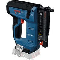
- Montage
- General Safety Rules for Pneumatic Tools
- 1) Work area safety
- 2) Pneumatic tool safety
- 3) Personal safety
- 4) Pneumatic tool use and care
- 5) Service
- SafetyWarnings for Compressed-air Nailers/Staplers
- | English
- Functional Description
- Read all safety warnings and all instructions.
- Intended Use
- Product Features
- Noise/Vibration Information
- Wear hearing protection!
- | English
- Declaration of Conformity C
- Assembly
- Connecting the Air Supply (see figure A)
- Connecting the Air Supply to the Pneumatic Tool
- Loading the Magazine (see figures B1-B2)
- Operation
- Actuation systems
- - Single actuation with safety run
- - Contact actuation
- Starting Operation
- Working with Single Actuation (see figure C)
- Working with Contact Actuation (see figure D)
- Working Advice
- | English
- Emptying the Magazine
- Adjusting the Depth Stop (see figure E)
- Clearing Jams (see figures F1-F3)
- Changing a Magazine Rail (see figure G)
- Changing the Workpiece Protector (see figure H)
- Stationary Use of the Pneumatic Tool (see figure I)
- Transport and Storage
- Maintenance and Service
- Maintenance and Cleaning
- Lubricating the Pneumatic Tool (see figure J)
- | English
- Maintenance Schedule
- Correction of Malfunctions
- | English
- Accessories
- After-sales Service and Customer Assistance
- www.bosch-pt.com
- Great Britain
- Ireland
- Australia, New Zealand and Pacific Islands
- Republic of South Africa
- Customer service
- Gauteng - BSC Service Centre
- KZN - BSC Service Centre
- Western Cape - BSC Service Centre
- Bosch Headquarters
- Disposal
- Montaje
- Montagem
- Montaggio
- Montering
- Tilslutning til luftforsyningen (se Fig. A)
- Avfallshantering
- Asennus
- Συναρμολόγηση
- Suvtnpnon kal Service
- Montaj
- Hava ikmalinin baglanmasi (Bakiniz: Sekil A)
- Montaž
- Montáz
- Pripojeni na zdroj vzduchu (viz obr. A)
- Zprcovani odpadu
- Montáž
- Összeszerelés
- IpoaHTaTe N yuHTbBaTe BCE
- 218|Pycckn
- Ottncahne yHKcnn
- PnmuHeHne To Ha3HaueHHIO
- H306paXeHHbIe coCTaBbIe qactn
- AaHbIe IIO wMy n Bn6paun
- OeBaIte HayHnKn!
- C6opka
- TIOKIAUOeHne K HCTouHHky CxAtoro BO3aYxa (cm.pnc.A)
- TPhcoeAnHeHne THTaHn CXKaTbIM BO3dYxOM K THeBMOHHCTpymEnty
- 3apraKa maraunHa (cm. pnc. B1-B2)
- Hcnoab3yTeToaBkoOpnHnHaHbHbIe TpHHaAeXHoCTN Bosch (cm. 一 TexHmecKe
- Pa6ota c HcTpymeHTOM
- CnCTemblcnycka
- - Odnapa30BbI cnYcK C BbldepkkoJ
- -KoHTaKTHbIcTnyck
- BkIoueHne
- Pa6oTa c OAnHopa3OBbIM CnYcKOM (cm. pnc. C)
- 222|Pycckn
- Pa6ota c KOHTAKTHbIM CNyckOM (CM. PHC. D)
- Yka3aHHI TO TIPMHHeHHIO
- OnopoKHeHMeMa3nHa
- Hactpoika orpaHnHTeRA rAynHbI (cm.pnc.E)
- YdaHHe 3aCtpBbux rBo3eM (cm.pnc.F1-F3)
- IIaH TOAdepKKn B 6e3yIpeuHOM TexHHueckOM COCTOHHN
- 3o6paxehi KOMTOHEHTN
- 232|YkpaIHcbKa
- MOHTAX
- TIIkAIOueHHo AKepea TOBiTpra (ANB.MaA.A)
- TIIaKluoehnI IOBITpDo THeBMaTHuHOrO pHaAdy
- 234|YkpaHcbKa
- 3aTOBHeHHMaRa3Ha (AIB.MaHOHKn B1-B2)
- Eknpnyatauaia
- CnCTEmn nycky
- - ODHopa3OBH NpCK 3 Pny3OIO
- -KoHTaKTHm Tyck
- Touatok po60tn
- Po6ota i3 oDHopa3OBHM TycKOM (AHB.MaA.C)
- Po6oTaI3 KOHTAKTHM TnycKOM (ANB.MaA.D)
- Bka3iBkn 0oDo po6oTu
- TpeaTHM,AK HAcTPOIBaTH PnHaA,MiHrTH TpnaAa46o BiKaIactn IHeBMaTHuHH NpHaA,BUMKHITb NOBITp. Li nTopeaKaAblHi
- CtoopoxHeHHa Mara3Ha
- HactpoIOBAHHo6MExyBaHa rAN6HHn (mB.MaA.E)
- BndaenH3 3aCPTpAunx uBxiv (MBA. MaA. F1-F3)
- 3amHa peKm MaarHnA (Mn. MaG)
- 3maeHHH THeBMOITpHaAdy (mB.MaJ)
- IIaH IIATpIMKn B 6e3dOraHHOMy texHiHOMy cTaHi
- Montare
- Racordarea la instalata de alimentare cu aer (vezi figura A)
- Eliminare
- yka3aHna 3a 6e3oPacha pa6ota
- 06u yka3aHn 3a 6e3oTncha pa6ota c THeB MaTHnHH HnCTpyMeHTn
- BHIMAHIME
- CbxpaHbAte yka3aHnTa 3a 6e0nacha pa6oTa rPnxnBO.
- 1)Be30nachOHT Ha pa6oTHOTO MCTO
- 2) Be3oNaChpa6Ota c THeBMaTHuHn HhCTpyMeHTn
- 3) Be3o3nacnoct Ha xopa
- Yka3aHHa 3a 6e3oTachpa6oTa C THEBMATHH MaHHn 3a 3a6hBaHe
- Pa6oTeTe c PpeAa3Hn OuaHa.
- Ako KpeTeKHeEeMeHcTe 3aKaHHN B THeBMaTHHHH HcTpMEnT, PpeKbChTe He3a6abHO PoDaBaHeTo Ha CbCTeh Bb3dYx.
- HnΦopmaun3a n3bYBaH yum n Bn6paun
- Pa6oTeTe C wymo3aRyWHTeAN!
- Aekapaua 3a cbOTBETBNE C
- MOnTnpaHe
- BkAIOU4BaHe KbM CnCTemata 3a CrbCTe H Bb3dYx (BnXTeΦnR.A)
- BkUOHaHe hcnTeMaTa 3a crbcTeH Bb3Axy KbM THEBMaTHHHN HhCTpyMeHT
- 3apexKaHe Ha Mara3nHa (BnXTe nHyprn B1-B2)
- Pa6ota
- ChcTemHaH3CTpeBAhe
- -EDHHHNO H3cTpeABAHe c Ae6AoKnpaHe Ha TpeAa3nteA
- -KoHTaKTHO H3CTpeAbaHe
- BkIouBaHe
- Pa6oTa c eAnHnHn H3ctpeAa (BHXTe FmR.C)
- Pa6oTa c KOHTaKTHO H3CTpeABAHe (BnKTe fHr. D)
- Yka3aHnHa 3a pa6ota
- H3Pp3BaHe Ha Mara3nHa
- HactpoBaHe Ha bA6OHHNOrpaHHnTeA (BnXTeΦnR.E)
- N3BaXdaHe Ha 3aKAnHeH KpeTeXeH eAeMeHT (BnXTe fHyprn F1-F3)
- CmHa Ha WnHaTa Ha Mara3Hb (BHXTe pHyp a G)
- CMHa Ha rymHpHaTa IIpeIa3Ha BLoKKa (BnXTe fHpya H)
- CtauHapno H3IOA3BaHe Ha THeBMaTHUHHN HHCTpyment(BHXTeΦnI)
- TpaHcIopTpHaNe HcbXpaHbBaHe
- TIOAdbpxKaHe n cepBn3
- TIOADBpKaHe NTOUNCBaHe
- OTCTpaHbAhe Ha TIOBpeAn
- Montaža
- Prikljucak na snabdevanje vazduhom (pogledajte sliku A)
- Prikljucak za snabdevanje vazduhom na pneumatski alat
- Transport is spremanje
- Gaisa padeve (attels A)
- Pneimatiska instrumenta pievlenosana gaisa spiedientiklam
- Magazinas uzpildisana (skatit attelus B1-B2)
- Montavimas
- Prijungimas prie suslègto oro tiekimo sistemas (ziür. pav. A)
- (B1-B2, gall)
- i1jxylg
- Joull
- Jaaai Jaaai
- a_i a a_i 的最小值为 k .
- Lc:wsLjSjB
- S
- aLc:ww,2jLgogag gjjolal
Brand : BOSCH
Model : GSN 9034 DK Professional
Category : Stapler