BS 75 - Sander FESTOOL - Free user manual and instructions
Find the device manual for free BS 75 FESTOOL in PDF.
Frequently Asked Questions - BS 75 FESTOOL
User questions about BS 75 FESTOOL
0 question about this device. Answer the ones you know or ask your own.
Ask a new question about this device
Download the instructions for your Sander in PDF format for free! Find your manual BS 75 - FESTOOL and take your electronic device back in hand. On this page are published all the documents necessary for the use of your device. BS 75 by FESTOOL.
USER MANUAL BS 75 FESTOOL
Original Instructions - Belt sander 11

natural_image
Close-up of a Festool electric drill press tool with green mesh tube and black housing (no visible text or symbols)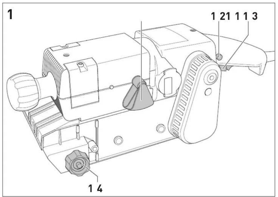
text_image
1 1 21 1 1 3 1 4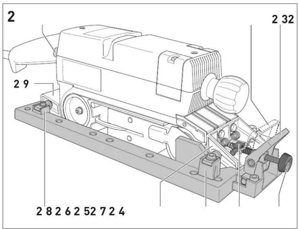
text_image
2 2 9 2 8 2 6 2 52 7 2 4 2 32
text_image
3 3 1 3 2 3 3 3 4 3 5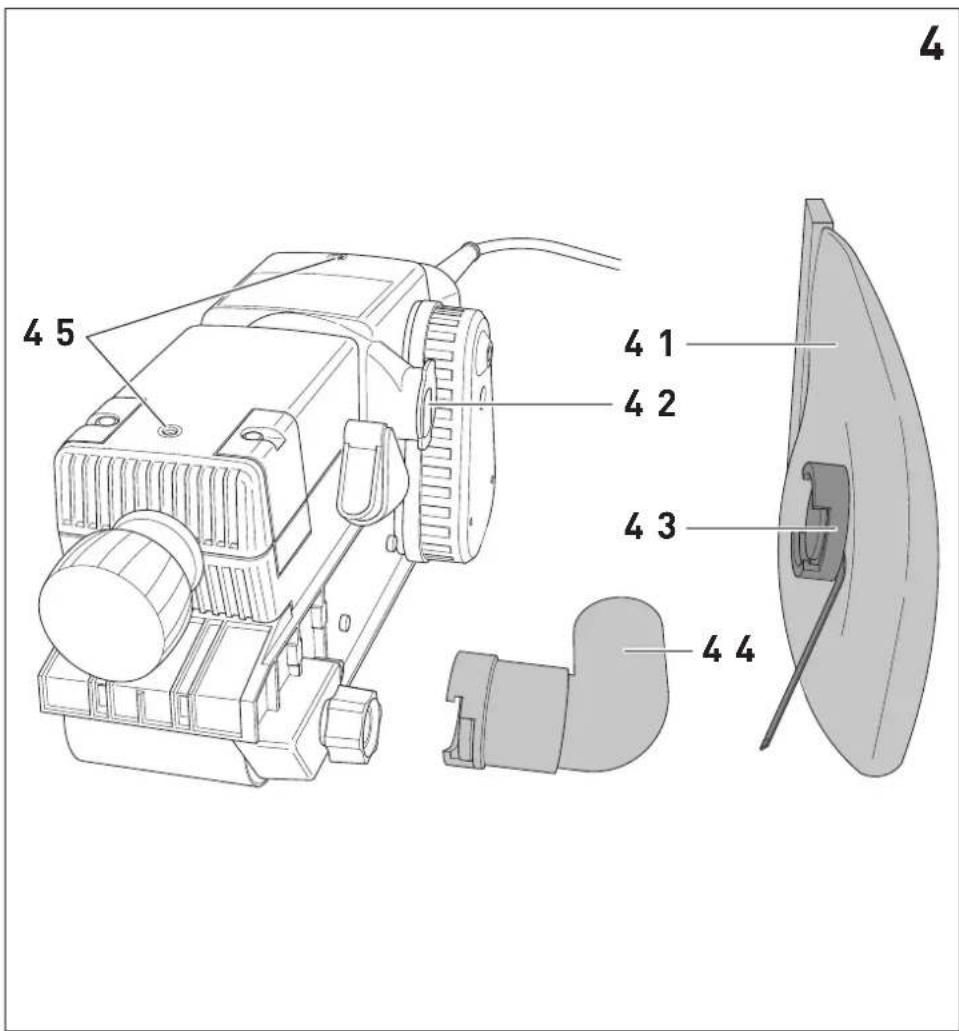
text_image
4 4 5 4 1 4 2 4 3 4 4 4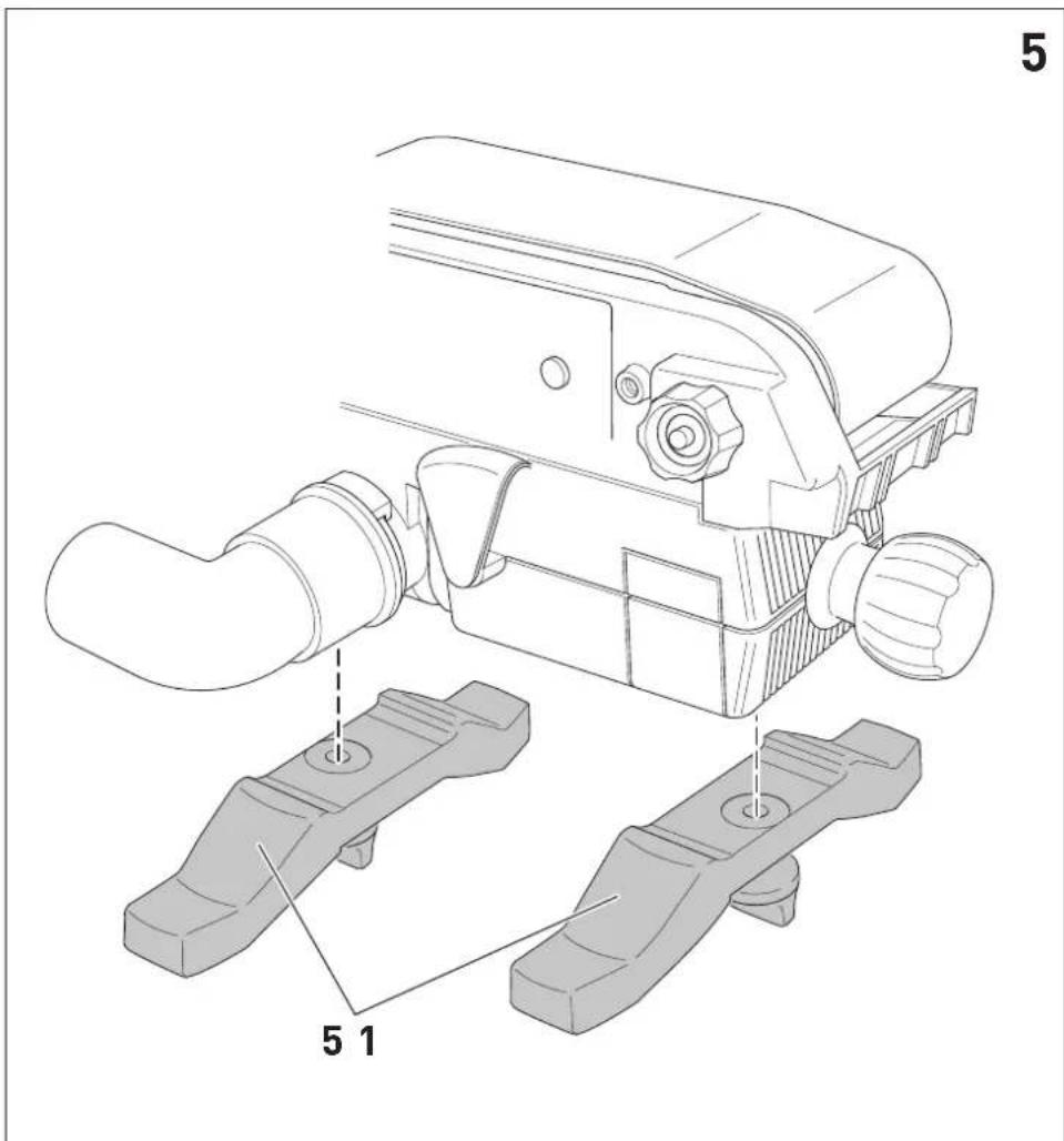
text_image
5 5 1en EC-Declaration of Conformity. We declare under our sole responsibility that this product is in conformity with all relevant provisions of the following directives including their amendments and complies with the following standards:
Markus Stark Head of Product Development
text_image
i.V. R C b x a v o t tRalf Brandt Head of Product Conformity
| Schleifen | a_h = 6,0 m/s^2 |
| K = 2,0 m/s^2 |
Power consumption 1010 W
Belt speed
no-load 200 - 380 m/min
rated load 150 - 320 m/min
Weight
according to EPTA-Procedure 01:2014 4.0 kg
The specified illustrations can be found at the beginning of the operating instructions.
Graphical symbols

tion. Danger!

d the operating instructions/notes

ar ear protection!

Wear a dust mask!

Wear protective goggles!

Wear protective gloves!
Safety class II

Do not dispose of it with domestic waste.
1 Safety warnings
1.1 General power tool safety warnings

WARNING! Read all safety warnings, instructions, illustrations and specifications provided with this power tool.
Failure to follow all instructions listed below may result in electric shock, fire and/or serious injury.
Save all warnings and instructions for future reference.
The term „power tool“ in the warnings refers to your mains-operated (corded) power tool or battery-operated (cordless) power tool.
1.2 Tool-specific safety warnings
- Hold the power tool by insulated gripping surfaces, because the sanding surface may contact its own cord. Cutting a "live" wire may make
exposed metal parts of the power tool "live" and could give the operator an electric shock.
- Use clamps or another practical way to secure and support the workpiece to a stable platform mainly in case of grinding small pieces. Holding the work by your hand or against the body leaves it unstable and may lead to loss of control.


Wear suitable personal protection equipment: ear protection to reduce the risk of damaging your hearing; protective goggles; protective gloves when handling tools and coarse materials.
- Harmful/toxic dusts can occur during your work (e.g. lead-containing paint, some types of wood). Contact with these dusts, especially inhaling them, can represent a hazard for operating personnel or persons in the vicinity. Comply with the safety regulations that apply in your country. Connect the electric power tool to a suitable extraction system. To protect your health, wear a P2 protective mask.
- The manufacturer's handling and processing instructions must be observed without fail if explosive or self-igniting dusts are likely to occur during sanding.
- Before doing any work to the machine, first remove the plug from the mains.
- Only insert plug when machine is switched off.
- Use the machine only for dry sanding.
- Always connect to a dust bag or external dust extraction device.
- When sanding take care the cable does not come into contact with the sanding belt.
- Check the plug and the cable regularly in order to prevent a hazard. In the event of damage, these must be replaced by an authorised service workshop only.
- Do not use torn or damaged sanding belts.
- Only for AS/NZS: The tool shall always be supplied via residual current device with a rated residual current of 30 mA or less.
1.3 Emission levels
Typically, the noise levels that are determined in accordance with EN 62841 (see EC declaration of conformity) are as follows:
| BS 75 E | |
| Sound pressure level | L_PA = 88 dB(A) |
| Sound power level | L_WA = 99 dB(A) |
| Uncertainty | K = 3 dB |

ear protection!
Vibration emission value ah (vector sum for three directions) and uncertainty K measured in accordance with EN 62841 (see EU Declaration of Conformity):
| Sanding | a_h = 6.0 m/s^2 |
| K = 2.0 m/s^2 |
The specified emissions values (vibration, noise)
- are used to compare machines.
- They are also used for making preliminary estimates regarding vibration and noise loads during operation.
- They represent the primary applications of the power tool.

CAUTION
The noise emissions during actual use of the power tool can differ from the declared values depending on the ways in which the tool is used especially what kind of workpiece is processed.
Identify safety measures to protect the operator that are based on an estimation of exposure in the actual conditions of use (taking account of all parts of the operating cycle such as the times when the tool is switched off and when it is running idle in addition to the trigger time).
2 Intended use
All-purpose sander for sanding wood, plastics and building materials; using the appropriate sanding belts, surfaces, edges, lippings and rebates can be rough or fine sanded; with the Type BS 75 E – Set, using the sanding frame, high-grade workpiece surfaces such as veneers etc., can be sanded.
The operation and application of the sander can be extended with the accessories listed.
Metals and materials that contain asbestos must not be processed. Sparks may be created when processing metals, which increase the risk of fire. Generally accepted accident prevention regulation and the enclosed »Safety Instructions« for the avoidance of accidents when working with the electric tools, must be complied with.
The manufacturer is not liable for damages caused by unauthorized changes or the use of external accessories with the machine.

The user is liable for damage and injury resulting from incorrect usage!
3 Mains supply
The mains voltage must match the voltage on the rating plate.
Fuse for 230 V: 10 Amp slow action or equivalent automatic cut-out.
Connection is also possible to sockets without an earthing contact, as protective insulation (Class II) is present.
Only use a run out extension lead with a cross section of 3 × 1.5 mm^2 , max. 20 m, ( 3 × 2.5 mm^2 , max. 50 m). When tool is used outdoors, use only extension cords intended for use outdoors and so marked.
4 Electronic adaptation of belt speed on types BS 75 E

The control electronics permits the infinitely variable adaptation of the belt speed.
| Setting of set wheel Belt speed(no load) | |
| 1 200 m/min | |
| 2 240 m/min | |
| 3 300 m/min | |
| 4 340 m/min | |
| 5 360 m/min | |
| 6 380 m/min | |
The most suitable belt speed must be found by trial and error when starting work, because there are several prime factors which influence the choice, such as the surface and quality of the workpiece, the make of abrasive belt and grit, skill of the operator etc.
The figures shown in the table are only recommended values.
| Application Setting | of set wheel | Grit |
| Solid wood, fine 4 - 6 | 100 | |
| Veneer 3 - 4 120 | ||
| Chipboard | 5 - 6 100 | |
| Plastics | 1 - 4 100 | |
| Steel | 2 - 4 | 80 |
| Paint remova | 1 - 3 | 24 |
The belt speed is infinitely adjustable up to the maximum setting while work is in process.
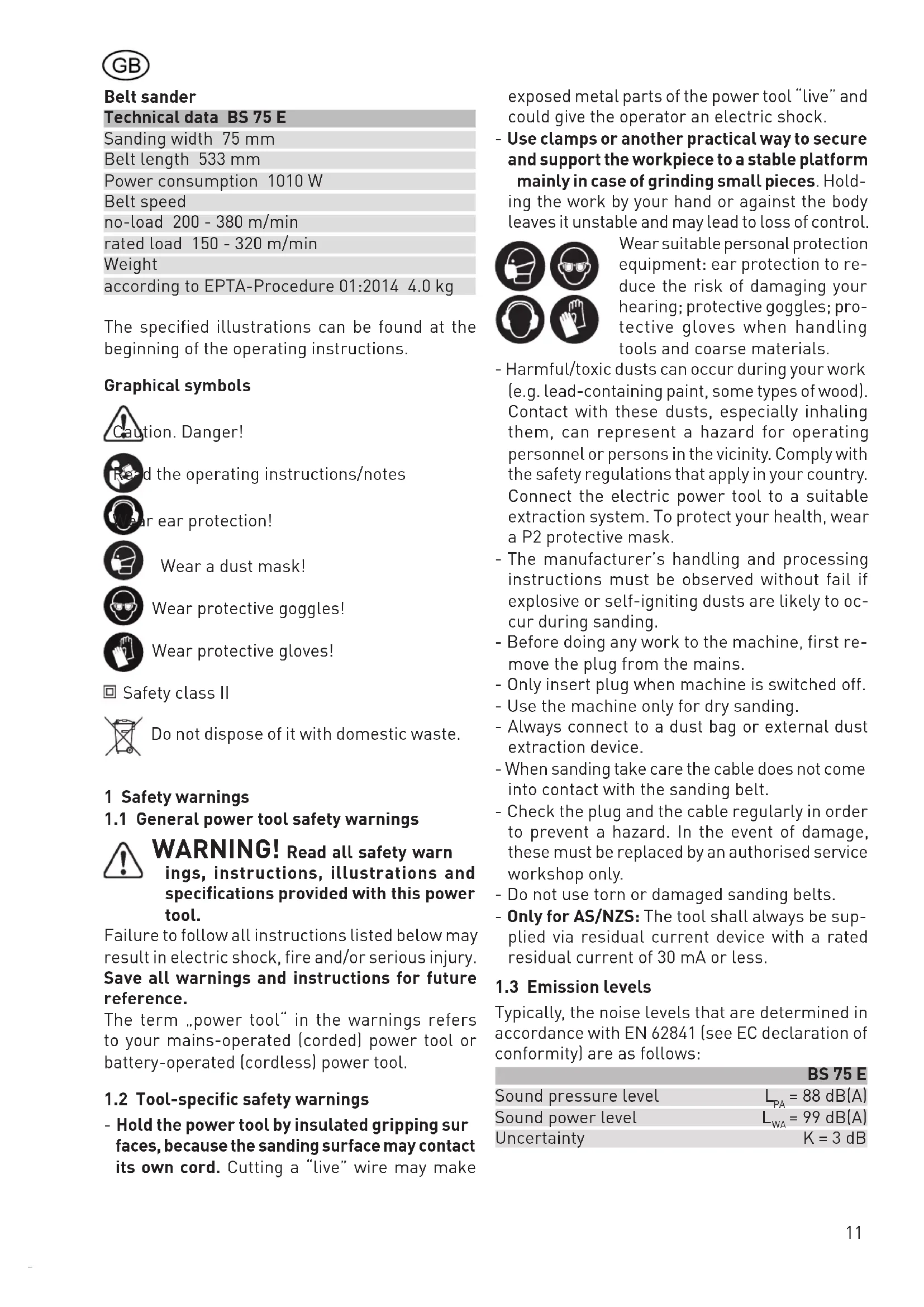
This is done by turning the set wheel [2 1]. It must be remembered that at low speed settings the sander has a lower power output. In order to
avoid overloading, therefore, the speed has to be increased by turning the set wheel if it turns out that the belt speed falls sharply while working.
5 Operation
Only to be switched on when the machine is raised. Using the lock on button [1-2] , the switch [1-3] can be locked in the ON position. Before sanding, check the alignment of the belt and if necessary, adjust by turning the adjusting knob [1-4] until the belt is flush with the outside edge of the sanding face.
Using both hands, place the machine straight onto the workpiece to be sanded.
The actual weight of the machine provides adequate sanding pressure to produce good sanding quality.
The expelled cooling air can be guided in the most favourable direction by the ducting flap [1-1].
5.1 Working with the sanding frame in the case of type BS 75 E - Set
Set the machine with the knurled head screw [2-4], so that when it is placed on the workpiece surface the sanding belt does not engage.
The sanding belt is engaged by turning the knurled head screw towards the plus symbol until the belt makes contact.
Continue turning the knurled screw to achieve the desired depth of stock removal (1 complete turn corresponds to a height adjustment of 0.4 mm). When interrupting or on completing work, the sander is raised from the working position [2-3] set to a position of rest [2-2] by means of an eccentric lever.
By swinging the eccentric lever back to working position the depth of stock removal set previously is again obtained.
5.2 Taking the sanding frame off
Press down the knurled head screw [2-4] until the shank [2-5] springs out of the spring catch and the machine can be withdrawn from the rear.

The sander and sanding frame are aligned for optimum accuracy at the factory by suitable adjustment of the guiding struts.
For this reason do not remove the guiding struts.
5.3 Assembling the sanding frame
Make sure that the glide pins [2-6, 2-8] fixed to the sanding frame engage front and back in the grooves of the guide struts [2-7, 2-9] . Slide the sander downwards along the grooves until the shank [2-5] engages.
5.4 Changing the sanding belt
Pull the lever [3-5] forward; the belt is now slack and can be removed.
When inserting the sanding belt, make sure that the running direction of the belt (usually indicated by an arrow on the inside) matches the running direction of the machine [3-4].
Tighten the belt again with the lever and align when running.
5.5 Dust extraction
The dust produced while working can be detrimental to health, combustible or explosive. Suitable safety measures are necessary.
The dust bag [4-1] with the adopter [4-3] is attached to the exhaust duct [4-2] by means of a bayonet catch by turning to the right.
The dust bag is removed for emptying by turning it to the left.
At the time of fixing, ensure that the leaf spring stud touches the belt housing.
The dust extraction system will continue to function effectively as long as the bag is emptied in good time.
For working with the protection of the environment in mind it is advisable to use the Festool dust extraction system.
The connecting socket from the suction hose can be connected using the adapter [4-4] which is supplied as standard.
5.6 Stationary use (partly accessories)
- Attach both feet [5-1] via the two threaded holes [4-5]. Important: the straight edges of the feet must face inwards.
- Make sure that the machine is standing firmly: use clamps to attach the feet to the base.
- Do not work with oversized and heavy workpieces that could damage the tool.
6 Service and maintenance

Always remove the power supply plug from the socket before carrying out any work on the machine.

All maintenance and repair work which requires the motor casing to be opened may only be carried out by an authorised service centre.

Customer service and repair. Only through manufacturer or service workshops: Please find the nearest address at:: www.festool.com/service
Use only original Festool spare parts!
Order No. at: www.festool.com/service
plementation in national law, used electric power tools must be collected separately and handed in for environmentally friendly recycling.
Information on REACH:
www.festool.com/reach
When the graphite coating on the pad lining [3 3] is heavily worn this has to be replaced. To do this the 3 cheese-head screws [3 1] are loosened and the strip [3 2] removed.
A sanding support for rough work at high removal rates is available.
The belt sander requires practically no maintenance.
The lubrication for the antifriction bearings and gears is designed to last for the service life of the machine.
It is advisable to clean the air intake and outlet ports and the dust suction and extraction channel occasionally with compressed air while the sander is running and at standstill.
This will prevent the openings from becoming clogged with dust.
The special carbon brushes only wear down to a minimum length.
Thereafter the power cuts out automatically and the sander comes to a stop.
The motor housing may only be opened by an authorised Festool service workshop, since specialist knowledge is required for assembly.
7 Accessories
The accessory and tool order number can be found in your Festool catalogue or on the Internet under "www.festool.com".
Sanding belts
Resin bonded X cloth belts:
sanding wood and fibreboard.
Combination belts:
for removing paint and remains of concrete, sanding plaster surfaces.
8 Disposal
Do not throw the power tool in your household waste! Dispose of the machine, accessories and packaging at an environmentally-responsible recycling centre! Observe the valid national regulations.
EU only: In accordance with European Directive on waste electrical and electronic equipment and im-
F
Ponceuse à bande
| Ponçage | a_h = 6,0 m/s^2 |
| K = 2,0 m/s^2 |
| Lijado | a_h = 6,0 m/s^2 |
| K = 2,0 m/s^2 |
secondo procedura EPTA 01:2014 4,0 kg
| Levigatura | a_h = 6,0 m/s^2 |
| K = 2,0 m/s^2 |
conform EPTA-procedure 01:2014 4,0 kg
| Schuren | a_h = 6,0 m/s^2 |
| K = 2,0 m/s^2 |
| Slipning | a_h = 6,0 m/s^2 |
| K = 2,0 m/s^2 |
| Hionta | a_h = 6,0 m/s^2 |
| K = 2,0 m/s^2 |
Vekt iht. EPTA-Procedure 01:2014 4,0 kg
De bildene det vises til finner du foran i bruker-veiledningen.
Symboler

Advarsel mot generell fare

Anvisning/les merknader!

øreklokker!

Bruk støvmaske!

Bruk vernebriller.

Bruk vernehansker!

Beskyttelsesklasse II

| Sliping | a_h = 6,0 m/s^2 |
| K = 2,0 m/s^2 |
EPTA-Procedure 01:2014 4,0 kg
| Lixar a | _h = 6,0 m/s^2 |
| K = 2,0 m/s ^2 |
EPTA-Procedure 01:2014 4,0 kg
| Szlifowanie | a_n = 6,0 m/s^2 |
| K = 2,0 m/s | ^2 |