EAG750RS - Grinder RYOBI - Free user manual and instructions
Find the device manual for free EAG750RS RYOBI in PDF.
| Product type | Grinder (angle grinder) |
| Brand | RYOBI |
| Model | EAG750RS |
| Grinding wheel diameter | 115 mm |
| Grinding wheel thickness | 6 mm |
| Supply voltage | 230-240 V ~50 Hz |
| Rated power | 750 W |
| No-load speed | 11 000 min⁻¹ |
| Maximum peripheral speed | 4 800 m/min |
| Spindle thread | M14 |
| Total length | 310 mm |
| Net weight | 2,35 kg |
| Sound pressure level (Lp) | 87,5 dB(A) (K=3 dB) |
| Sound power level (Lw) | 98,5 dB(A) (K=3 dB) |
| Vibration level (ah) | 5,9 m/s² (K=1,5 m/s²) |
| Double insulation | Yes |
| Switch | Sliding with continuous locking |
| Protective guard | Adjustable (max rotation 90° each side) |
| Auxiliary handle | Included (threaded) |
| Power-on indicator | Yes (lights up when connected to mains) |
| Spindle lock button | Yes |
| Service wrench | Included |
| Maintenance | Regular cleaning of ventilation slots; annual lubrication at an authorised service centre |
| Included accessories | Auxiliary handle, service wrench, grinding disc (depending on country) |
Frequently Asked Questions - EAG750RS RYOBI
User questions about EAG750RS RYOBI
0 question about this device. Answer the ones you know or ask your own.
Ask a new question about this device
Download the instructions for your Grinder in PDF format for free! Find your manual EAG750RS - RYOBI and take your electronic device back in hand. On this page are published all the documents necessary for the use of your device. EAG750RS by RYOBI.
USER MANUAL EAG750RS RYOBI
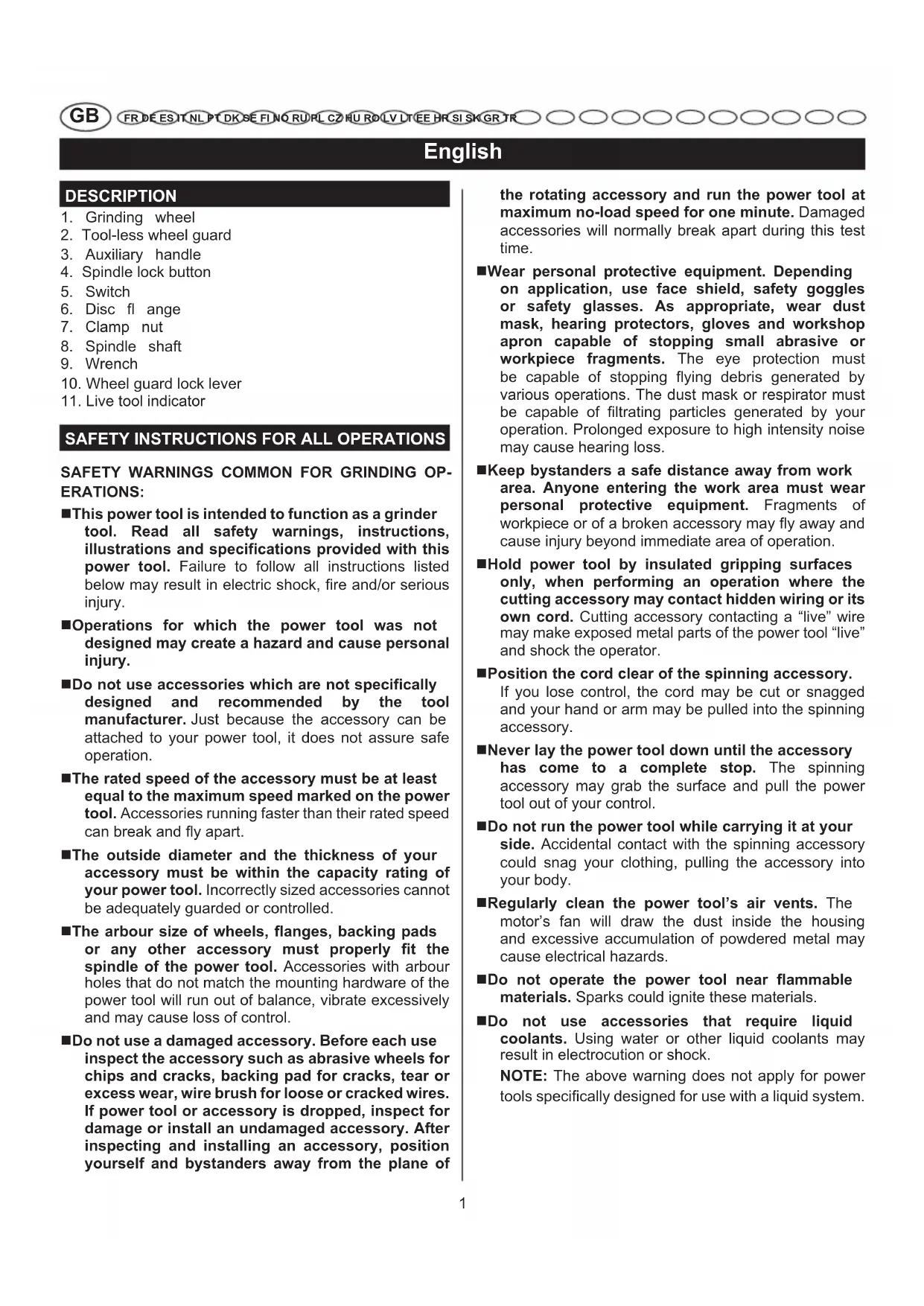
natural_image
Technical line drawing of a YOBL angle grinder with visible brand mark and no textual annotations


natural_image
Technical line drawing of a mechanical device with no visible text or symbols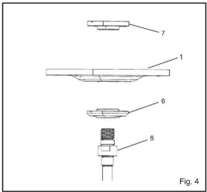
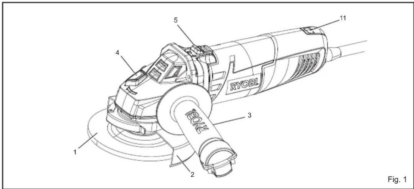
Important! It is essential that you read the instructions in this manual before operating this machine.
- Grinding wheel
- Tool-less wheel guard
- Auxiliary handle
- Spindle lock button
- Switch
- Disc fl ange
- Clamp nut
- Spindle shaft
- Wrench
- Wheel guard lock lever
- Live tool indicator
SAFETY INSTRUCTIONS FOR ALL OPERATIONS
SAFETY WARNINGS COMMON FOR GRINDING OPERATIONS:
■This power tool is intended to function as a grinder tool. Read all safety warnings, instructions, illustrations and specifications provided with this power tool. Failure to follow all instructions listed below may result in electric shock, fire and/or serious injury.
■Operations for which the power tool was not designed may create a hazard and cause personal injury.
■Do not use accessories which are not specifically designed and recommended by the tool manufacturer. Just because the accessory can be attached to your power tool, it does not assure safe operation.
■The rated speed of the accessory must be at least equal to the maximum speed marked on the power tool. Accessories running faster than their rated speed can break and fly apart.
■The outside diameter and the thickness of your accessory must be within the capacity rating of your power tool. Incorrectly sized accessories cannot be adequately guarded or controlled.
■The arbour size of wheels, flanges, backing pads or any other accessory must properly fit the spindle of the power tool. Accessories with arbour holes that do not match the mounting hardware of the power tool will run out of balance, vibrate excessively and may cause loss of control.
■Do not use a damaged accessory. Before each use inspect the accessory such as abrasive wheels for chips and cracks, backing pad for cracks, tear or excess wear, wire brush for loose or cracked wires. If power tool or accessory is dropped, inspect for damage or install an undamaged accessory. After inspecting and installing an accessory, position yourself and bystanders away from the plane of
the rotating accessory and run the power tool at maximum no-load speed for one minute. Damaged accessories will normally break apart during this test time.
■Wear personal protective equipment. Depending on application, use face shield, safety goggles or safety glasses. As appropriate, wear dust mask, hearing protectors, gloves and workshop apron capable of stopping small abrasive or workpiece fragments. The eye protection must be capable of stopping flying debris generated by various operations. The dust mask or respirator must be capable of filtrating particles generated by your operation. Prolonged exposure to high intensity noise may cause hearing loss.
■Keep bystanders a safe distance away from work area. Anyone entering the work area must wear personal protective equipment. Fragments of workpiece or of a broken accessory may fly away and cause injury beyond immediate area of operation.
■Hold power tool by insulated gripping surfaces only, when performing an operation where the cutting accessory may contact hidden wiring or its own cord. Cutting accessory contacting a "live" wire may make exposed metal parts of the power tool "live" and shock the operator.
■Position the cord clear of the spinning accessory. If you lose control, the cord may be cut or snagged and your hand or arm may be pulled into the spinning accessory.
■Never lay the power tool down until the accessory has come to a complete stop. The spinning accessory may grab the surface and pull the power tool out of your control.
■Do not run the power tool while carrying it at your side. Accidental contact with the spinning accessory could snag your clothing, pulling the accessory into your body.
■Regularly clean the power tool's air vents. The motor's fan will draw the dust inside the housing and excessive accumulation of powdered metal may cause electrical hazards.
■Do not operate the power tool near flammable materials. Sparks could ignite these materials.
■Do not use accessories that require liquid coolants. Using water or other liquid coolants may result in electrocution or shock.
NOTE: The above warning does not apply for power tools specifically designed for use with a liquid system.
English
FURTHER SAFETY INSTRUCTIONS FOR ALL OPERATIONS
Kickback and related warnings
Kickback is a sudden reaction to a pinched or snagged rotating wheel, backing pad, brush or any other accessory. Pinching or snagging causes rapid stalling of the rotating accessory which in turn causes the uncontrolled power tool to be forced in the direction opposite of the accessory's rotation at the point of the binding.
For example, if an abrasive wheel is snagged or pinched by the workpiece, the edge of the wheel that is entering into the pinch point can dig into the surface of the material causing the wheel to climb out or kick out. The wheel may either jump toward or away from the operator, depending on direction of the wheel's movement at the point of pinching. Abrasive wheels may also break under these conditions.
Kickback is the result of power tool misuse and/or incorrect operating procedures or conditions and can be avoided by taking proper precautions as given below.
■Maintain a firm grip on the power tool and position your body and arm to allow you to resist kickback forces. Always use auxiliary handle, if provided, for maximum control over kickback or torque reaction during start-up. The operator can control torque reactions or kickback forces, if proper precautions are taken.
■Never place your hand near the rotating accessory. Accessory may kickback over your hand.
■Do not position your body in the area where power tool will move if kickback occurs. Kickback will propel the tool in direction opposite to the wheel's movement at the point of snagging.
■Use special care when working corners, sharp edges etc.. Avoid bouncing and snagging the accessory. Corners, sharp edges or bouncing have a tendency to snag the rotating accessory and cause loss of control or kickback.
■Do not attach a saw chain woodcarving blade or toothed saw blade. Such blades create frequent kickback and loss of control.
ANGLE GRINDER SAFETY PRECAUTIONS
■Check that the speed marked on the grinding wheel is equal to or greater than the rated speed of the tool.
■Ensure that the dimensions of the grinding wheel are compatible with the tool and that the wheel fits the spindle.
■Grinding wheels must be stored in a dry place.
■Do not store objects on top of the grinding wheels.
■Grinding wheels must not be used for any operation other than grinding.
■Grinding wheels must be stored and handled with care in accordance with the manufacturer's instruction.
■Inspect the grinding wheel before use to ensure that it is not chipped or cracked. Chips or cracks can cause the wheels to shatter, resulting in possible serious injury.
■Ensure that the wheel is fitted in accordance with this manual.
■Ensure that the grinding wheel is correctly mounted and tightened before use and run the tool at no-load speed for 30 seconds in a safe position. Stop immediately if there is considerable vibration or if other defects are detected. If this condition occurs, check the tool to determine the cause.
■Do not use separate reducing bushings or adapters to adapt large hole grinding wheels.
■Check that the work piece is properly supported.
■Use only recommended accessories.
■Ensure that sparks resulting from use do not create a hazard, e.g., do not hit people, or ignite flammable substances.
■Always use protective safety glasses and ear protectors.
■Use other personal protective equipment such as gloves, apron and helmet when necessary.
■Never place the tool on the floor or other surfaces while it is running. Grinding wheels continue to rotate after the tool is switched off. Never touch the wheel or place it on the floor or other surfaces while it is rotating.
■The flange and clamp nut must have same outer diameter.
■Use the tool only for approved applications. Never use coolants or water or use the tool as a fixed tool.
■Grip the tool securely with both hands while operating.
SPECIFICATIONS
Model EAG750RS EAG750RB
Wheel diameter 115 mm (4.5 in) 125 mm (5 in)
Thickness 6 mm 6 mm
Voltage 230 V - 240 V \~ 230 V - 240 V \~ 50 Hz 50 Hz Input 750 W 750 W
Spindle thread M14 M14
English
Rated speed 11,000 min ^-1 11,000 min ^-1
Overall length 310 mm 310 mm
Net weight 2.35 kg 2.4 kg
NOTE: Be sure to check the nameplate on the product, because the voltage is subject to change depending on the area in which the product is to be used.
Maximum circumferential speed of grinding wheel: 4,800 m/min
Example of calculation:
3.14 × 125 × 11,000/1,000 = 4,320
Circumferential speed of grinding wheel 4,320
Wheel diameter 125
Rated speed of grinder 11,000
STANDARD ACCESSORIES
■ Auxiliary handle
Wrench
A grinding wheel is included in the standard accessories for some countries.
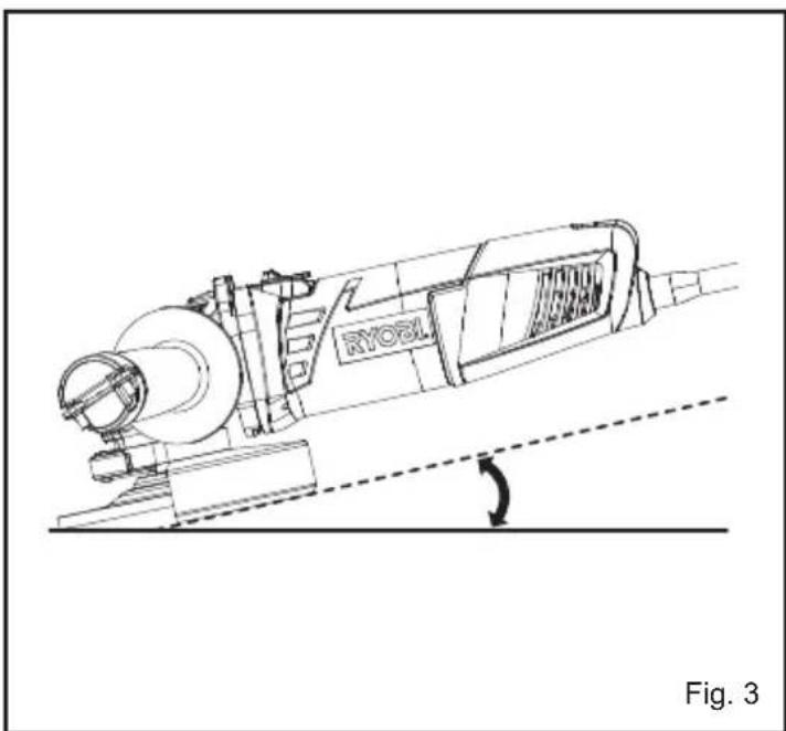
OPERATION
See Figure 3.
WARNING
Keep safety guards in place. Never cover the air vents since they must always be open for proper motor cooling.
The key to efficient operating is controlling the pressure and surface contact between the disc and work piece. Flat surfaces are ground at an acute angle, usually 10 to 20 degrees with the work piece. Allow the disc to reach full speed before starting to grind. Too great an angle causes concentration of pressure on a small area which may gouge or burn work surface.
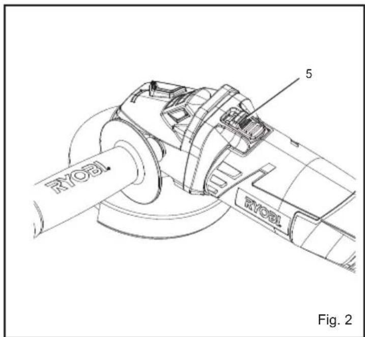
SWITCH
See Figure 2.
■ This tool is started and stopped by sliding and releasing the switch.
■ For the convenience of continuous operation, slide the switch along then press the front end down to lock it.
■ To release the lock, press the rear end of the switch.
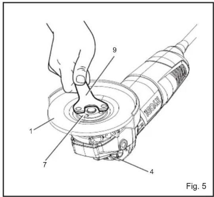
MOUNTING THE GRINDING WHEEL
See Figure 4-5.
■ Attach the disc flange and the wheel on the spindle before fitting the clamp nut.
■ Ensure that the wheel is correctly seated over the boss on the disc flange and clamp nut.
■ Depress the lock button located on the right side of gear case.
■ Using the wrench provided, tighten the clamp nut in a clockwise direction.
WARNING
Check carefully whether or not there are cracks in the wheel. Replace a cracked wheel immediately.
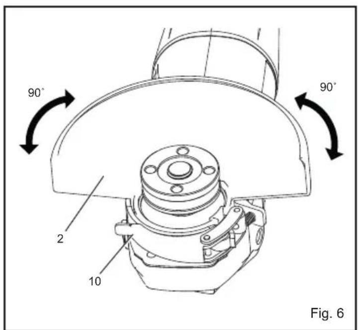
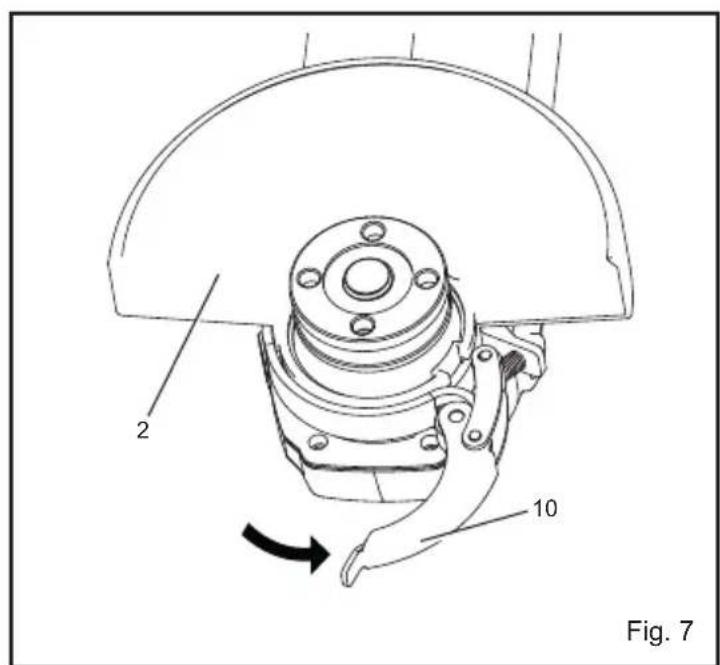
TOOL-LESS WHEEL GUARD
See Figure 6-7.
Release the wheel guard lock lever then turning the tool-less wheel guard to the desired position. The maximum turning axle is 90° on either side; otherwise the guard can't be locked.
LIVE TOOL INDICATOR
This tool features a live tool indicator which illuminates as soon as the tool is connected to the supply. This warns the user that the tool is connected and will operate when the switch is pressed.
MAINTENANCE
After use, check the tool to make sure that it is in good condition.
It is recommended that you take this tool to a Ryobi Authorized Service Center for a thorough cleaning and lubrication at least once a year.
WARNING
Do not make any adjustments while the motor is in motion.
Always disconnect the power cord from the socket before changing removable or expendable parts (grinding disc, cutting disc, etc.), before lubricating or working on the unit.
WARNING
To ensure safety and reliability, all repairs should be performed by an authorized service center or other qualified service organization.
English
Save these instructions.
ENVIRONMENTAL PROTECTION
Recycle raw materials instead of disposing of as waste. The machine, accessories and packaging should be sorted for environmental-friendly recycling.
SYMBOL

Safety Alert
V Volts
Hz Hertz

Alternating Current
Watts
no No-load speed
min ^-1 Revolutions or reciprocations per minute

CE Conformity

Double insulation

Wear ear protection

Wear eye protection

Please read the instructions carefully before starting the machine.
Waste electrical products should not be disposed of with household waste. Please recycle where facilities exist. Check with your Local Authority or retailer for recycling advice.
Français
DESCRIPTION
Modelo EAG750RS EAG750RB
Modello EAG750RS EAG750RB
Model EAG750RS EAG750RB
Schijf-diameter 115 mm (4.5 in) 125 mm (5 in)
Dikte 6 mm 6 mm
| Spanning | 230 V - 240 V ~50 Hz | 230 V - 240 V ~50 Hz |
| Input | 750 W | 750 W |
| Schroefdraad van as | M14 | M14 |
| Nominaal toerental | 11,000 min-1 | 11,000 min-1 |
| Totale lengte | 310 mm | 310 mm |
| netto gewicht | 2.35 kg | 2.4 kg |
Modelo EAG750RS EAG750RB
Model EAG750RS EAG750RB
Slibeskivens diameter
115 mm (4.5 in) 125 mm (5 in)
Tykkelse
6 mm
6 mm
Dansk
Malli EAG750RS EAG750RB
Suomi
Model EAG750RS EAG750RB
Model EAG750RS EAG750RB
Model EAG750RS EAG750RB
Modelis EAG750RS EAG750RB
Diska diamets 115 mm (4.5 in) 125 mm (5 in)
Biezums 6 mm 6 mm
| Spriegums | 230 V - 240 V ~ | 230 V - 240 V ~ |
| 50 Hz | 50 Hz |
Ieeja 750 W 750 W
| Vārpstas vītne M14 | M14 |
VISU DARBU VEIKSMU SAUGOS INSTRUKCIJOS
ÜLDISED OHUTUSJUHISED
ABRASIIVLÕIKAMISEL JÄRGIGE ALLPOOL ESITA-TUD JUHISEID:
POSEBNA SIGURNOSNA PRAVILA
■Provjerite je li brzina označena na brusu jednaka ili viša od nominalne brzine alata.
■Provjerite je li promjer brusa usklađen s alatom te je li brus pravilno umetnut na osovinu.
■Bruseve treba spremiti na suho mjesto.
■Ne stavljajte predmete na brusove.
■ Bruseve treba upotrebljavati samo za brušenje, a ne u druge svrhe.
■Oprezno spremajte i koristite se brusevima u skladu s uputama proizvođača.
■Prije uporabe brusa uvjerite se da nije okrnjen te da na njemu nema pukotina. U protivnom brus moæe puknuti, što moæe dovesti do teških tjelesnih ozljeda.
Model EAG750RS EAG750RB
| Wheel diameter | 115 mm (4.5 in) | 125 mm (5 in) |
| Debljina 6 mm | 6 mm | |
| Napon | 230 V - 240 V ~ 50 Hz | 230 V - 240 V ~ 50 Hz |
| Ulaz | 750 W | 750 W |
| Navoj osovine M14 | M14 | |
| Nazivna brzina | 11,000 min ^-1 | 11,000 min ^-1 |
| Ukupna dužina | 310 mm | 310 mm |
| neto težina | 2,35 kg | 2.4 kg |
Model EAG750RS EAG750RB
Premer koluta 115 mm (4.5 in) 125 mm (5 in)
Slovensko
Debelina 6 mm 6 mm
| Napetost | 230 V - 240 V ~ | 230 V - 240 V ~ |
| 50 Hz | 50 Hz |
Vhod 750 W 750 W
Navoj vretena M14 M14
| Nazivna hitrost | 11,000 min ^-1 | 11,000 min ^-1 |
| Skupna dolžina | 310 mm | 310 mm |
| neto teža | 2.35 kg | 2.4 kg |
Model EAG750RS EAG750RB
Priemer kotúča 115 mm (4.5 in) 125 mm (5 in)
Debelina 6 mm 6 mm
| Napätie | 230 V - 240 V ~ | 230 V - 240 V ~ |
| 50 Hz | 50 Hz |
Vstup 750 W 750 W
| Závit vretena | M14 | M14 |
| Menovitá rýchlost' | 11,000 min ^-1 | 11,000 min ^1 |
Release the wheel guard lock lever then turning the toolless wheel guard to the desired position. The maximum turning axle is 90° on either side; otherwise the guard can't be locked.
Always disconnect the power cord from the socket before changing removable or expendable parts (grinding disc, cutting disc, etc.), before lubricating or working on the unit.
⚠️ ПРОЕІДОПОІНЗН
Model EAG750RS EAG750RB
| Wheel diameter | 115 mm (4.5 in) 125 mm (5 in) |
Kalınlık 6 mm 6 mm
| Gerilim | 230 V - 240 V ~ | 230 V - 240 V ~ |
| 50 Hz | 50 Hz |
Giriş 750 W 750 W
Mil dişleri M14 M14
| Nominal hiz | 11,000 min ^1 | 11,000 min ^1 |
| Toplamuzunluk | 310 mm | 310 mm |
| net ağırlık | 2.35 kg | 2.4 kg |
GB Conformance to technical regulations
FR Conformité aux normes techniques
All Ryobi products are guaranteed against manufacturing defects and defective parts for a period of twenty four (24) months from the date stated on the original invoice drawn up by the retailer and given to the end user.
Deterioration caused by normal wear and tear, unauthorised or improper use or maintenance, or overload are excluded from this guarantee as are accessories such as battery packs, light bulbs, blades, fittings, bags, etc. In the event of malfunction during the warranty period, please take the NON-DISMANTLED product, along with the proof of purchase, to your retailer or nearest Authorised Ryobi Service Centre.
This warranty in no way affects your legal rights concerning defective products.
FR
GARANTIE - CONDITIONS
The vibration emission level given in this information sheet has been measured in accordance with a standardised test given in EN 60745 and may be used to compare one tool with another. It may be used for a preliminary assessment of exposure. The declared vibration emission level represents the main applications of the tool. However if the tool is used for different applications, with different accessories or poorly maintained, the vibration emission may differ. This may significantly increase the exposure level over the total working period.
An estimation of the level of exposure to vibration should also take into account the times when the tool is switched off or when it is running but not actually doing the job. This may significantly reduce the exposure level over the total working period. Identify additional safety measures to protect the operator from the effects of vibration such as: maintain the tool and the accessories, keep the hands warm, organisation of work patterns.
FR
AVERTISSEMENT
DECLARATION OF CONFORMITY
We declare under our sole responsibility that this product is in conformity with the following standards or standardized documents: 2006/42/EC, 2006/95/EC, 2004/108/EC, EN55014-1, EN55014-2, EN61000-3-2, EN61000-3-3, EN60745-1, EN60745-2-3, EN62233. Noise level [K=3dB(A)]: Lp=87.5dB(A) Lw=98.5dB(A) Vibration level [K=1.5m/s ^2 ]: ah=5.9m/s ^2
FR
DÉCLARATION DE CONFORMITÉ
Type: EAG750RS / EAG750RB

Jun 2010

Techtronic Industries
Name of company: TECHTRONIC INDUSTRIES CO. LTD.
Address: 24/F, CDW BUILDING, 388 CASTLE PEAK ROAD, TSUEN WAN, HONG KONG.
Web: www.ttigroup.com
Name/Title: Brian Ellis / Vice President - Engineering
Signature:

Technical File at
Name of company: TTI EMEA
Address: MEDINA HOUSE, FIELDHOUSE LANE, MARLOW, BUCKS, SL7 1TB, UNITED KINGDOM.
Web: www.ttigroup.com
Name/Title: Carl A. Jeffries / Head of Ryobi Product Marketing
Signature:
Trademarks:
The use of the trademark Ryobi is pursuant to a license granted by Ryobi Limited.