
ME 545 C - Lawn mower VIKING - Free user manual and instructions
Find the device manual for free ME 545 C VIKING in PDF.
| Product type | Electric lawn mower with traction |
| Brand | Viking |
| Model | ME 545 C |
| Dimensions (L x W x H) | 147 x 48 x 102 cm |
| Weight | 32 kg |
| Power supply | 230 V ~ 50 Hz, 10 A |
| Power consumption | 1600 W |
| Cutting width | 43 cm |
| Cutting height | 25 to 80 mm (7 positions) |
| Cutting height adjustment | Centralized |
| Grass catcher | 60 L, with fill indicator |
| Blade type | Cutting blade (sharpenable, interchangeable) |
| Blade speed | 2800 rpm |
| Wheel drive | Vario rear wheel drive (2.4 to 4.0 km/h) |
| Front/rear wheel diameter | 180 mm / 200 mm |
| Guaranteed sound power level (LWA) | 94 dB(A) |
| Vibration level (ahw) | 5.20 m/s² |
| Safety | Blade brake, thermal protection, 30 mA residual current circuit breaker recommended |
| Maintenance | Cleaning after each use, regular sharpening and balancing of the blade |
| Common spare parts | Blade (ref. 6340 702 0100), blade screw, grass catcher |
| Repairability | Have repairs carried out by an authorized Viking dealer |
| Warranty | Warranty subject to compliance with the operating instructions |
Frequently Asked Questions - ME 545 C VIKING
User questions about ME 545 C VIKING
0 question about this device. Answer the ones you know or ask your own.
Ask a new question about this device
Download the instructions for your Lawn mower in PDF format for free! Find your manual ME 545 C - VIKING and take your electronic device back in hand. On this page are published all the documents necessary for the use of your device. ME 545 C by VIKING.
USER MANUAL ME 545 C VIKING
natural_image
Exterior view of a lawn mower with adjustable handle and wheels (no text or symbols visible)DE Gebrauchsanleitung
EN Instruction manual
FR Manuel d'utilisation
NL Gebruiksaanwijzing
IT Istruzioni per l'uso
ES Manual de Instrucciones
PT Manual de utilização
NO Bruksanvisning
SV Bruksanvisning
Fl Käyttöohjeet
DA Betjeningsvejledning
PL Instrukcja obstugi
SK Návod na použitie
TR Kullanım Kılavuzu
HU Használati útmutató
CS Návod k použití
LT Naudojimo instrukcija
EL Οδηγίες χρήσης
0478 121 9909 E. M2. A13. Eco. Printed in Germany © 2006 - 2013 VIKING GmbH, A - 6336 Langkampfen / Kufstein
2002/96/EC, 2004/108/EC,
2006/95/EC, 2006/42/EC
Thank you for choosing a VIKING quality product.
This product has been produced using state-of-the-art production methods and extensive quality assurance procedures, because our goal is only achieved if you, the customer, are satisfied with your appliance.
If you have any questions concerning your appliance, please contact your dealer or our sales department directly.
I hope that your VIKING appliance will give you great enjoyment.

Dr. Peter Pretzsch
Manager
VIKING is continually striving to further develop its range of products; we therefore reserve the right to make alterations to the form, technical specifications and equipment level of our standard equipment.
The information and illustrations in this manual are therefore subject to alterations.
Table of contents
Notes on the instruction manual 2
Appliance overview 2
For your safety 2
Preparatory measures 3
Mowing procedure 4
Maintenance and repairs 5
Warning - dangers caused by
electrical current 6
Description of symbols 6, 19
Standard equipment 6
Preparing the appliance
for operation 6
Assembling the handlebar 6
Upper handlebar 7
Installing the cable guide 7
Assembling the grass catcher bag 8
Height adjustment of the handlebar 8
Central cutting height adjustment 8
Attaching and detaching the
grass catcher bag 8
Notes on mowing and mulching 8
Mowing on slopes 9
Correct motor load 9
Thermal motor overload protection 9
If the mowing blade blocks 9
Initial operation of appliance 9
Electrical connection 10
Strain relief 10
Switching on the lawn mower 10
Switching off the lawn mower 10
Switching on the wheel drive 10
Switching off the wheel drive 11
Level indicator 11
Emptying the grass catcher bag 11
Maintenance 11
Cleaning the appliance 12
Electric motor, wheels and gearbox 12
Upper handlebar 12
Mowing blade maintenance 12
Removing the mowing blade 13
Sharpening the mowing blade 13
Checking the balance of the
mowing blade 13
Installing the mowing blade 14
Adjusting the wheel drive cable 14
Storage (winter break) 14
Environmental protection 15
Standard spare parts 15
Minimising wear and preventing damage 15
Troubleshooting 16
Technical specifications 18
Circuit diagram 19
CE - Manufacturer's declaration of conformity 19
Transport 19
Service schedule 20
Note:
This instruction manual constitutes original manufacturer's instructions in the sense of EC Directive 2006/42/EC.
Notes on the instruction manual
Illustration symbols

This symbol serves to link the Figs. on the illustration pages with the corresponding text passages in the instruction manual.
The illustrations can be found at the front of the instruction manual
Designation of text passages
The operating steps described may be designated in different ways.
Operating step without direct reference to a figure.
Example:
- Sharpen blades evenly to prevent vibration due to imbalance.
Operating step with direct reference to the relevant figure to be found in the illustration pages (at the front of the instruction manual), with a corresponding reference to the item number in the figure.
Example:
Loosen
1=bolt
2= lever ...
General lists, which do not refer to the illustrations.
Example:
- use of the product for sporting or competitive events
In addition to descriptions of operating steps, this instruction manual includes text passages containing important additional information. Such passages are identified using the symbols described below in order to especially emphasise them in the instruction manual:

Danger of accident and risk of injury to persons and serious damage to property.

Information for better use of the appliance and in order to avoid possible operating errors, which may result in damage to the appliance or to the individual components.
Viewing direction when “left” and “right” is used in the instruction manual: the user is standing behind the appliance (working position) and is looking forwards in the direction of travel.
Appliance overview

A Upper handlebar with controls
C Rotary handle
D Motor cover
E Carrying handle
F Upper housing
G Protection bumper
H Cutting height display
I Central cutting height adjustment
J Rotary handle for handlebar height adjustment
K Grass catcher bag
L Cable anti-kink protection
M Ejection flap
N Level indicator
For your safety

These safety regulations must be observed when working with the lawn mower.

Read the whole instruction manual before using the appliance for the first
time and keep in a safe place for future reference.
Ensure that you are familiar with the controls and use of the appliance. Never allow children or other persons who are not familiar with the instruction manual to use the lawn mower. The lawn mower must not be used by children under the age of 16. Local regulations may specify a minimum age for using the mower.
Never mow in the vicinity of other persons, particularly children, or animals.
Be aware that the person operating the appliance or the user is responsible for accidents involving third parties or their property.
- This appliance is not suitable for use by persons (including children) with impaired physical, sensory or mental faculties or those lacking the appropriate experience and/or knowledge, unless supervised by a person responsible for their safety or having received instructions on use of the appliance from such person. Children must be supervised, in order to ensure that they do not play with the appliance.
The lawn mower should not be operated after the consumption of alcohol, medications which impair reactions, or drugs.
Before initial use, advice should be obtained from the vendor or another expert.
Caution!
The lawn mower is only intended for mowing lawns; its use for other purposes is not permitted and may be dangerous or result in damage to the appliance.
Risk of accident!
Due to the physical danger to the user, the lawn mower must not be used, for example, for the following applications (incomplete list): for trimming bushes, hedges and shrubs, for cutting creepers, for care of lawn roofs and of balcony boxes, for clearing paths (vacuuming, blowing, clearing snow),
for shredding and chopping tree and hedge cuttings, for levelling earth mounds, e.g. mole hills
or for transporting cuttings (except in the grass catcher bag provided).
Preparatory measures

- Always wear robust shoes and long
trousers when mowing. Never mow barefoot or in sandals.
- Carefully inspect the complete area on which the appliance is to be used and remove any stones, sticks, wires, bones and other foreign objects which could be thrown up by the appliance.
- Before using the appliance, always ensure that the cutting tool, the fastening bolts and the entire cutting unit are in good condition.

- Caution! Danger of electric shock!
Particularly important for electrical safety are the mains cable, plug, on/off switch and connection cord. Damaged cables, connectors and plugs, or connection cords that do not conform to regulations must not be used, to prevent any risk of electric shocks. Therefore, check the connection cord regularly for signs of damage or ageing (brittleness).
- Never use the mower with damaged safety devices or safety guards, without functioning blade brake or attached safety devices, e.g. without the ejection flap or the grass-catching unit.
-
For safety reasons, always use an undamaged grass catcher bag.
-
The switch mechanisms installed in the appliance must not be removed or bypassed, e.g. by fixing a control lever to the handlebar.
- Only give (or lend) the appliance to persons who are familiar with this model and how to operate it. Always provide them with the instruction manual.
- Please observe the local regulations regarding permitted operation times for motor-driven gardening tools.
Mowing procedure

- Keep other persons away from the danger area.
- Place the appliance on an even surface for start-up. The appliance must not be tilted when starting the motor.
-
Follow the instructions for switching on the motor and only switch on when your feet are a safe distance away from the cutting tools.
-
Do not mow wet grass or mow in the rain. The risk of accidents is higher if the grass is wet (Danger of slipping).
- Only mow during the day or when there is enough light.
- Only mow at walking speed. Working quickly with the appliance increases the risk of injury due to stumbling, slipping etc.
- Always ensure good stability on slopes. Avoid mowing on excessively steep slopes in order to prevent loss of control of the appliance.
- Only mow at right-angles to the slope and never up or down the slope, in order to avoid being run over by the running lawn mower in the case of loss of control of the appliance or of falling.
- Be particularly careful when changing direction on a slope in order to prevent loss of control.
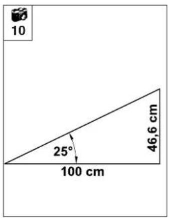
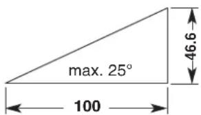
- For safety reasons, the appliance must not be used on slopes with an incline of more than 25° (46.6 %).
Risk of injury!
A slope inclination of 25^ corresponds to a vertical height increase of 46.6 cm for a 100 cm horizontal distance.
- Caution!
Be particularly careful when moving backwards and when pulling the lawn mower.
Risk of stumbling!
- Be particularly careful when turning the mower around or pulling it towards you.
- Switch off the motor if tilting of the mower is necessary when transporting over surfaces other than grass, and when pushing the mower to and from mowing areas.

Never open the grass ejection flap and/or
remove the grass catcher bag when the mowing blade is running. Rotating blades can cause injury.
- Avoid switching the appliance on repeatedly within a short period of time; particularly avoid "playing" with the on/off switch. Risk of motor overheating.
- Owing to the voltage fluctuations caused by this appliance during the run-up period, other devices connected to the same circuit may be subject to interference in the case of unfavourable power supply conditions. In this case, appropriate steps should be taken (e.g. connection to a different circuit than the one used by the affected device, or operation of the appliance using a circuit with a lower impedance).
- Never attach any objects to the handlebar (e.g. work clothing). Extension cables must never be wrapped around the handlebar.

- Caution!
Never put your hands or feet on or underneath
rotating parts. Never touch the rotating blade. Always keep away from the ejection aperture. Always observe the safety distance indicated by the handlebar.
Risk of injury!
- Never lift or carry a mower with the motor running or the mains lead connected.
- Switch off the motor and disconnect the plug:
- Before remedying blockages, including those in the ejection chute;
-
If the cutting tool has hit a foreign object. The cutting tool needs to be checked for possible damage;
-
Before checking, cleaning or working on the mower;
- If the mower begins to vibrate excessively. The cutting tool must be checked immediately;
- Before leaving the appliance unattended;
- Before lifting, or carrying the appliance;
- Before transporting the appliance.

STOP
- Beware of the cutting tool running on for several seconds coming to a still.
Maintenance and repairs

Before performing any work on the appliance, before adjusting or cleani
the mower, or before checking whether the connection cord is entwined or damaged, switch off the mower and disconnect the plug.
Only carry out maintenance work that is described in this instruction manual.
All other procedures should be carried out by a specialist dealer.
VIKING recommends that you have maintenance operations and repairs performed exclusively by a VIKING specialist dealer.
VIKING specialist dealers regularly attend training courses and are provided with technical information.
Only use high-quality tools, accessories and spare parts. Otherwise, there may be a risk of accidents resulting in personal injury or damage to the appliance.
VIKING recommends the use of original VIKING tools, accessories and spare parts. Their properties are optimally adapted to the appliance and the user's requirements.
VIKING original spare parts can be recognised by means of the VIKING spare parts number, the VIKING lettering and where applicable the VIKING spare parts symbol. The symbol alone may also feature on small parts.
- Ensure that all nuts, pins and bolts are securely tightened, so that the appliance is in a safe operating condition.
- If the cutting tool or the lawn mower hits an obstacle or a foreign object, the motor must be switched off, the plug disconnected, and an inspection performed by a specialist.
- The lawn mower must not be operated with a damaged or bent crankshaft.
Risk of injury through defective parts!
- Check the grass-catching unit regularly for wear, damage or for loss of functionality.
- In the interests of safety, replace all worn or damaged parts.
- Replace danger signs and warnings on the appliance which have become illegible. Your VIKING dealer has a stock of replacement stickers.
Warning - Dangers caused by electrical current
- The cord must be kept away from the blade when mowing.
- Only use extension cables that are insulated against moisture for outdoor use (see section: Initial operation).

- Although the drive motor is splashproof,
do not use the lawn mower when it is raining or in wet environments.
- Do not leave the appliance unprotected in the rain.
- Detach connection cords at the plug and socket and not by pulling on the connection cord.
- When operating the appliance, the socket must be fitted with a residual current operated device (max. trigger current: 30 mA), or such a device must be inserted when connecting the appliance. Your electrician can provide further information.
Description of symbols (1)
Caution!
Read the instruction manual before initial use.
Risk of injury!
Keep other persons away from the danger area.
Risk of injury!
Beware of the sharp mowing blade. The mowing blade runs on for several seconds after switching off (motor / blade brake). Before performing any work on the cutting tool, before carrying out maintenance and cleaning work, before checking whether the connection cord is entwined or damaged, or before leaving the mower unattended, switch off the motor and disconnect the plug.
Danger of electric shock!
Keep the connection cord away from the cutting tool.
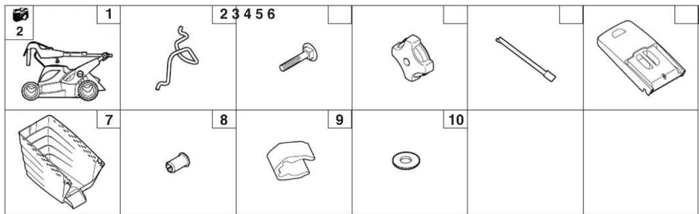
Standard equipment

Item Designation Qty.
1 Basic unit 1
2 Cable anti-kink
protection
ME 545, ME 545 C 1
ME 545 V 2
3 Flat head bolt 2
4 Rotary handle 2
5 Cable guide 1
(ME 545 C, ME 545 V)
6 Upper part of grass catcher bag 1
7 Lower part of grass catcher bag 1
8 Pin 2
9 Cable clip 2
(ME 545)
10 Washer 2
(ME 545)
• Instruction manual 1
Preparing the appliance for operation
NOTE

Place the appliance on level and firm ground to perform this work.
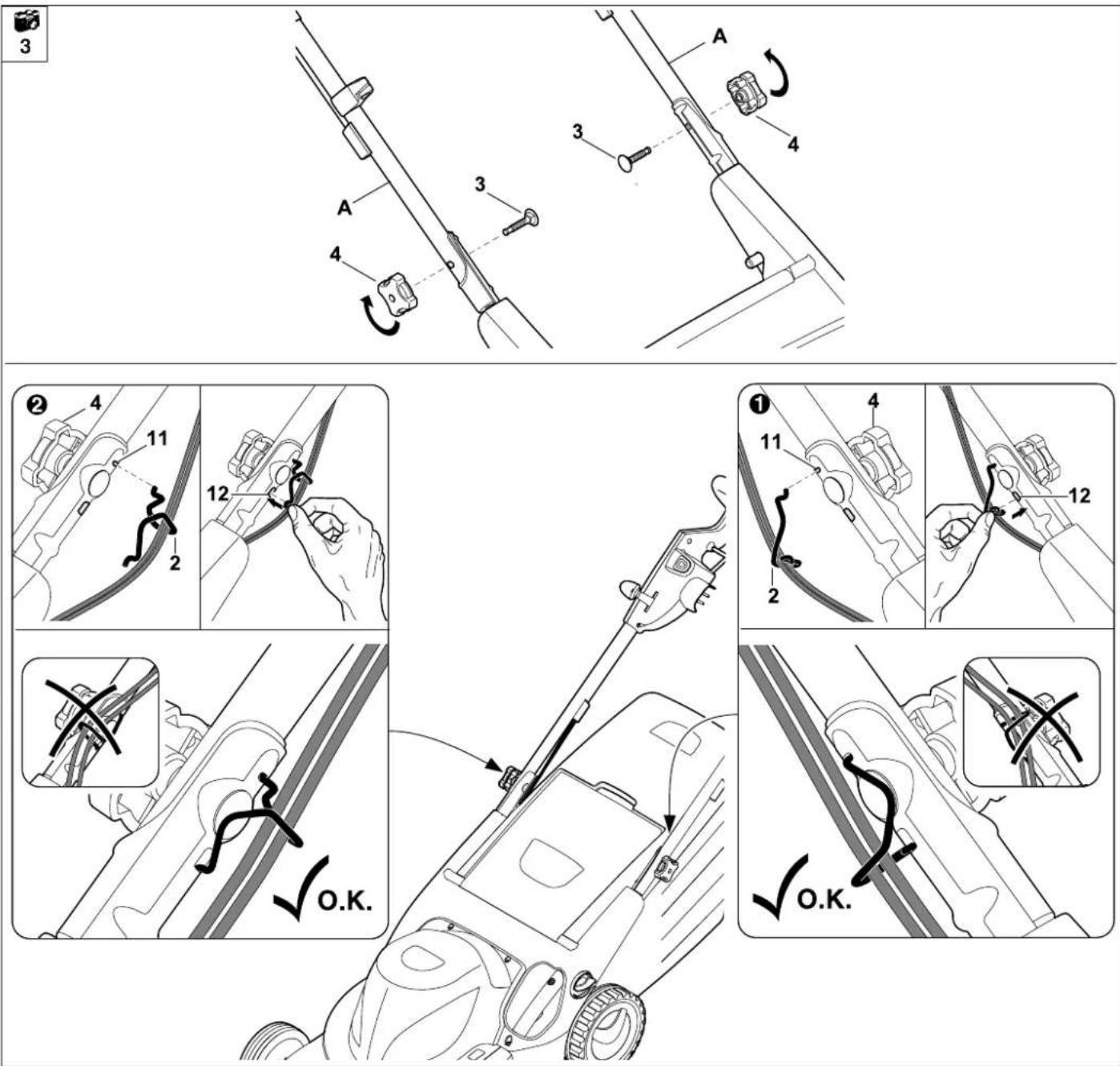
Assembling the handlebar

Assemble the handlebar:
Attach
A= handlebar to both parts of lower handlebar.
Insert
3= flat head bolts through bore from the inside to the outside and tighten securely with
4= rotary knobs.
NOTE

The machined grooves in the threads prevent the rotary handles from becoming completely detached from the bolts (safeguard against loss).
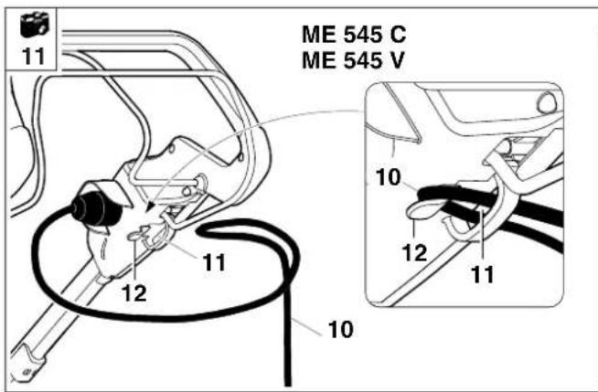
① Installing left anti-kink cable protection:
NOTE
Attach anti-kink cable protection (2) only as shown. Cables must be routed under the handlebar. Loosen the rotary handle (4) prior to assembly.
Insert all cables in 2= anti-kink cable protection. First insert the anti-kink cable protection into 11= upper bore of lower handlebar. Then engage anti-kink cable protection in 12= lower slot of lower handlebar.
② Installing right anti-kink cable protection:
NOTE
On model ME 545, there are no cables on the right-hand side of the handlebar. Only the left anti-kink cable protection (2) must therefore be installed on this lawn mower.
Assembly of the 2= right anti-kink cable protection is performed in the same way as on the left side.
Fold down the handlebar:
CAUTION
Risk of injury:
Before folding down the handlebar, switch off the machine and disconnect the power cable. No loads must be placed on the upper handlebar (e.g. hanging work clothing over the handlebar).
Danger of pinching!
The handlebar can be folded down by releasing the rotary knobs. For this reason, always hold the upper handlebar (A) with one hand at its highest point when you unscrew the rotary knobs.
Fold down the handlebar for cleaning, for space-saving transport and for storage of the appliance:
Loosen the
4= rotary handles until they move easily backwards and forwards in the machined grooves.
- Fold down the upper handlebar and rest it on the lower housing.
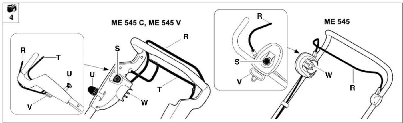
Upper handlebar
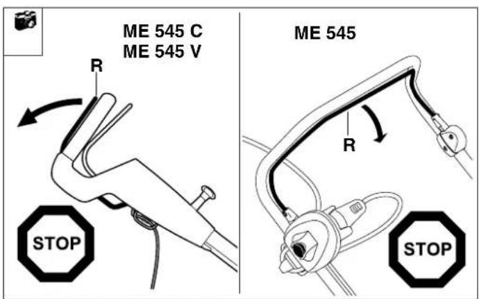
R= Motorstop lever
S= Start button
T= Wheel drive lever ME 545 V
U= Vario drive lever ME 545 V
V= Strain relief for connection cord
W= mains connection
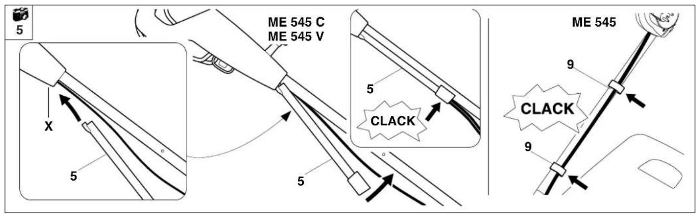
Installing the cable guide
ME 545 C, ME 545 V:
Insert 5= cable guide into the recess in the X= housing and turn towards the upper handlebar. Make sure that all cables are in the cable guide. Allow the cable guide to engage in the two bores provided using slight pressure.
ME 545:
Fasten cable to the upper handlebar using 9= cable clips.
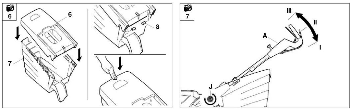
Assembling the grass catcher bag

Fit
6= upper part of grass catcher bag onto
7= lower part of grass catcher bag.
Press
8= pins through the apertures provided from the inside. Allow the grass catcher bag upper part to engage in the lower part using slight pressure.
Tighten the J= rotary handle again by turning clockwise.
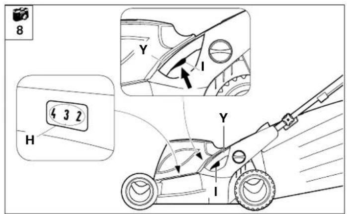
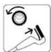
Central cutting height adjustment

CAUTION
Risk of injury!
The motor must be switched off before adjusting the cutting height. Ensure that you keep your feet far enough away from the cutting tool.
Height adjustment of the handlebar

The working height of the handlebar can be set to the following positions
I (low),
II (medium) and
III (high):
Loosen the
J= rotary handle for handlebar height adjustment by turning anti-clockwise (approx. five turns). Hold the
A= upper handlebar with both hands and bring to the desired position by moving up or down.
There are seven cutting height adjustment settings ranging from 25 mm to 80 mm.
Level 1 = lowest cutting height
Level 7 = highest cutting height
The
I= adjustment lever for the central height adjustment is located on the left side of the appliance (see illustration).
Hold the appliance at the
Y= handle and pull the
I= adjustment lever upwards and hold, in order to release the detent mechanism.
- Set the required cutting height by moving the appliance upwards or downwards.
This can be read off the
H= cutting height indicator.
Release the
I= adjustment lever again and allow the height adjustment to engage.
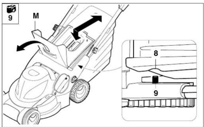
Attaching and detaching the grass catcher bag
CAUTION
Risk of injury!
The motor must be switched off before attaching and detaching the grass catcher bag.
Attaching:
Open the
M= ejection flap and hold it open.
The grass catcher bag is attached by engaging the
8= recesses in the grass catcher bag to the
9= mounting on the appliance.
Close the
M= ejection flap again manually.
Detaching:
Open the
M= ejection flap and hold it open.
Lift the grass catcher bag upwards, detach from the
9= mounting and remove.
Close the
M= ejection flap again manually.
Notes on mowing
NOTE

To ensure a perfect, thick lawn, mow regularly and keep the grass short.
Do not cut too short in hot, dry conditions as the lawn will dry out or burn in the sun and become unsightly.
The cutting pattern will be better with a sharp blade than with a blunt one. The blade must therefore be sharpened regularly (VIKING dealer).
CAUTION

Risk of injury!
Untangle any knots in the cord immediately.
If using a cable drum, the connection cord must be unwound completely, otherwise electrical resistance may cause loss of power and overheating.
NOTE
Ensure that handlebar adjustment is the same on the left and right sides.

Guide the connection cord behind you when mowing. Connection cords can be inadvertently cut when mowing and therefore involve a high accident risk. For this reason, mow so that the connection cord is always visible in the area of grass that has already been cut.
Mowing on slopes

For safety reasons, the lawn mower must not be used on inclines of more than 25°. A slope inclination of 25° (46.6%) corresponds to a vertical height increase of 46.6 cm for a 100 cm horizontal distance.
Correct motor load
Do not switch on the mower in tall grass or at the lowest cutting height.
The lawn mower load must never cause the motor speed to drop significantly. If the speed drops, select a higher cutting height setting and/or reduce the rate of feed.
Thermal motor overload protection
If an overload of the motor occurs during operation, the built-in thermal overload protection device automatically deactivates the motor.
Causes for an overload:
- mowing excessively high grass or with cutting height adjusted too low
- excessive rate of feed
- unsuitable or excessively long connection cord (voltage loss) (see section "Electrical connection")
- inadequate cleaning of the cooling air guide (inlet slots)
To recommence operation:
Resume normal operation of the appliance following a cooling period of approx. 10 min (depending on the ambient temperature) (see section "Initial operation")
If the mowing blade blocks
Switch off the motor immediately and disconnect the plug. Then eliminate the cause of the fault.
Initial operation of appliance
CAUTION

- Carefully inspect the complete area on which the appliance is to be used and remove any stones, sticks, wires, bones and other foreign objects.
- Start the motor in accordance with the instructions.
- Be particularly careful when turning the mower around or pulling it towards you.
- Risk of injury! Never put hands or feet on or underneath rotating parts.
- Always wear robust shoes and long trousers when mowing. Never mow barefoot or in sandals.
- Never mow in the vicinity of other persons, particularly children, or animals.
Electrical connection
Power supply and operating voltage must correspond (see identification plate).
The mains supply voltage must correspond to the specified rated voltage of the appliance.
The power supply cord must be adequately protected by fuse (see section “Technical specifications”).
Only connection cords which are no lighter than rubber sheathed cables H07 RN-F DIN/VDE 0282 and have a minimum cross section of 3 x 1.5 mm ^4 for cable lengths up to 25 m and 3 x 2.5 mm ^4 for cable lengths up to 50 m must be used.
The connectors of the connection cord must be made of rubber or have a rubber cover and conform to the standard DIN/VDE 0620.
This machine is intended for operation with a power supply having a system impedance of Z_max at the transfer point (house connection) of maximum 0.47 ohms (at 50Hz).
The user must ensure that the machine is only operated with a power supply which meets this requirement. If necessary, this information can be obtained from the local electric power company.
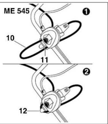
Strain relief

11
During mowing work, the strain relief prevents any unintentional disconnection of the connection cord and resulting possible damage to the mains connection on the appliance.
For this reason, the connection cord must be fed through the strain relief.
Form a loop with the
10= connection cord and guide it through the
11= opening.
Pass the loop over the
12= hook and tighten.
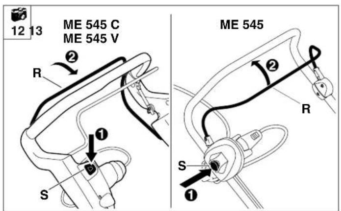
Switching on the lawn mower

12
NOTE

Do not start the motor in high grass or when the mower is set to the lowest cutting height, as this makes starting difficult.
Step 1 :
Press
S= start button and hold it down.
Step ② :
Press
R= Motorstop lever to the handlebar and hold.
- The start button can be released again after moving the motorstop lever.
Switching off the lawn mower

13
Release the
R= motorstop lever.
The motor and blade come to a standstill following a brief run-down time.
CAUTION

Risk of injury!
Always disconnect the mains plug when leaving the lawn mower unattended.
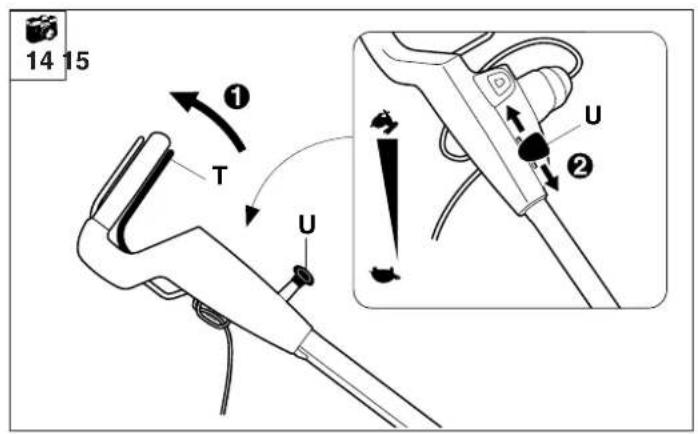
Switching on the wheel drive ME 545 V

14
NOTE

The wheel drive functions only when the motor is running.
The vario drive lever (U) must not be operated when the motor is stopped as this may result in damage to the drive mechanism (lever is blocked).
Step 1 :
Pull the
T= wheel drive lever to the handlebar and hold.
The wheel drive engages.
Step②:
For continuously variable speed increase, pull back the
U= vario drive lever; to reduce the speed, push the lever forwards.
Drive speed:
Continuously variable, from
2.4 km/h to 4.0 km/h
NOTE

The speed of the vario drive can be freely adjusted during drive operation, without switching the wheel drive off.
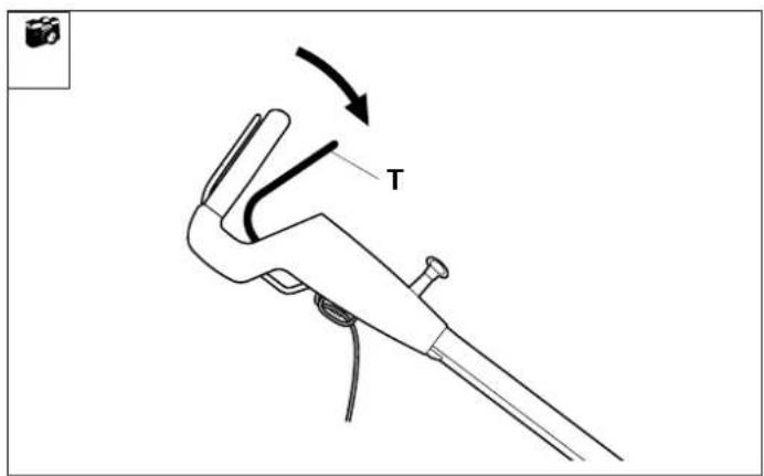
Switching off the wheel drive

To switch off the wheel drive, release the T= wheel drive lever.
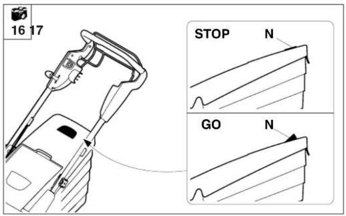
Level indicator

16
The grass catcher bag is equipped with a N= level indicator on the upper part of the grass catcher bag.
The flow of air that is created by the rotary movement of the mowing blade and is responsible for filling the grass catcher bag raises the level indicator:
The grass catcher bag is filled with cuttings.
When the grass catcher bag is full, this flow of air is reduced and the level indicator drops:
The grass catcher bag is full and must be emptied (see section "Emptying the grass catcher bag").
Emptying the grass catcher bag

18
CAUTION

Risk of injury!
The motor must always be switched off prior to emptying the grass catcher bag.
NOTE

A completely filled grass catcher bag can weigh up to 16 kg.
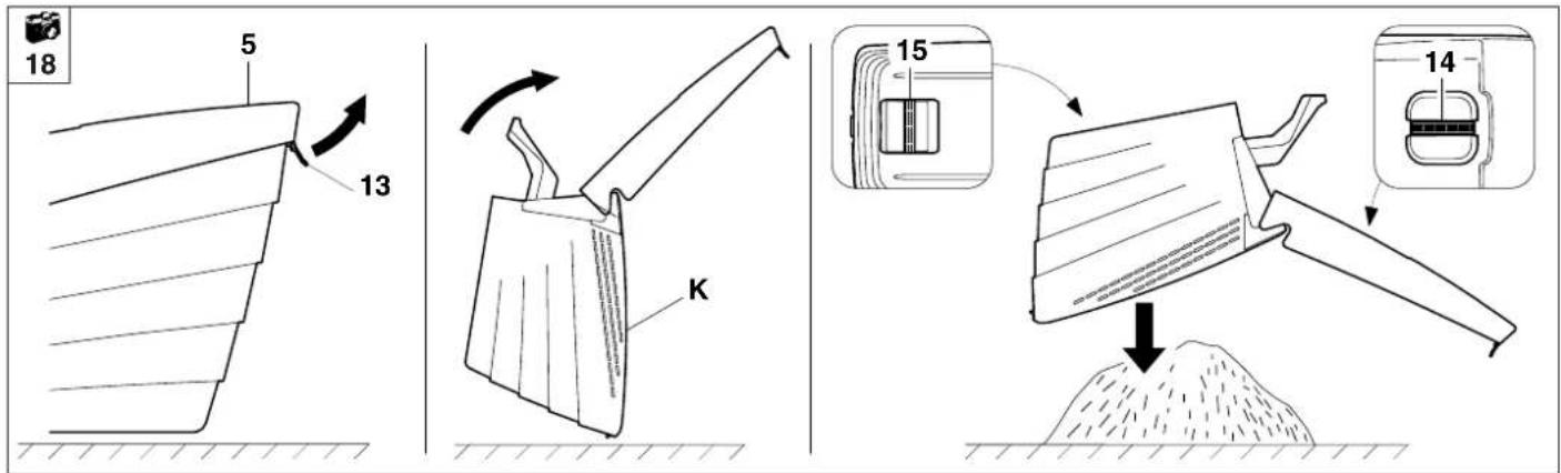
- Detach the grass catcher bag from the appliance (see section "Attaching and detaching the grass catcher bag"). Open the grass catcher bag at the
13= tab and open the 5= upper part of the grass catcher bag upwards.
Fold back the full
K= grass catcher bag.
The grass catcher bag can be held securely and emptied easily using the
14= handle (upper part of grass catcher bag) and the
15= handle (lower part of grass catcher bag).
Maintenance
CAUTION


Risk of injury!
In order to prevent inadvertent
starting of the motor, always disconnect the power cord prior to all maintenance and cleaning work, and prior to work on the mowing blade.

Risk of injury! Always wear gloves.
Do not touch the mowing blade until it has come to a standstill.
If you do not have the necessary expertise or auxiliary equipment, please always contact a specialist dealer.
VIKING recommends that you have maintenance operations and repairs performed exclusively by a VIKING specialist dealer.
VIKING recommends the use of original VIKING tools, accessories and spare parts.
Cleaning the appliance

Maintenance interval: Each time the appliance is used
Clean the appliance thoroughly each time it has been used. Care of the appliance will protect it against damage and extend its service life.
Remove dirt from the cooling air guide (inlet slots) between the motor cover and the lower housing to ensure that the motor is adequately cooled.
Clean the mowing blade. Clean the underside of the mower with water and a brush. Detach accumulated cutting deposits in the housing and in the ejection chute beforehand using a stick.
Never spray water onto motor components, seals, bearing points or electrical parts such as switches. This would result in expensive repairs.
Do not use aggressive cleaning agents. These cleaners can damage plastics and metals, impairing safe operation of your VIKING mower.
If you are unable to remove the dirt with water, using a brush or a cloth, VIKING recommends the use of a special cleaner (e.g. STIHL special cleaner).
CAUTION

Risk of injury!
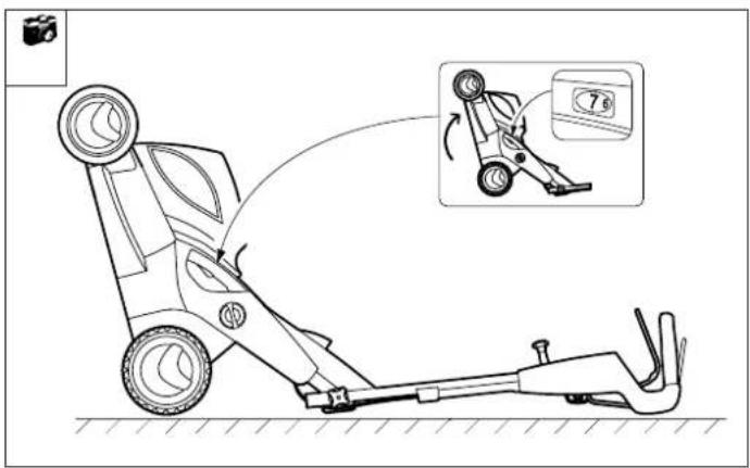
Before tilting upwards, place the mower on firm, horizontal and level ground and adjust it to the highest cutting level (level 7), otherwise the mower might tilt forwards again.
NOTE

Tilt up the front of the mower when carrying out cleaning or maintenance work. Before tilting, detach the grass catcher bag, fold down the upper handlebar (see section "Assembling the handlebar") and lift the ejection flap.
Electric motor, wheels and gearbox
The electric motor is maintenance-free.
The ball bearings of the wheels are maintenance-free.
The vario gearbox (ME 545 V) is maintenance-free.
Upper handlebar
Maintenance interval: Before each use
The upper handlebar is covered with a coating of insulation. Should this insulating coating become damaged, the upper handlebar must be replaced.
Risk of injury from an electric shock!
Mowing blade maintenance

CAUTION
Risk of injury!
If you do not have the necessary expertise or auxiliary equipment, please always contact a specialist dealer. (VIKING recommends VIKING specialist dealers).
VIKING recommends the use of original VIKING spare parts.
Maintenance interval: Before each use
Tilt the mower upwards into the cleaning position.
- Clean the mowing blade and check it for damage (notches or cracks) and wear; replace if necessary.
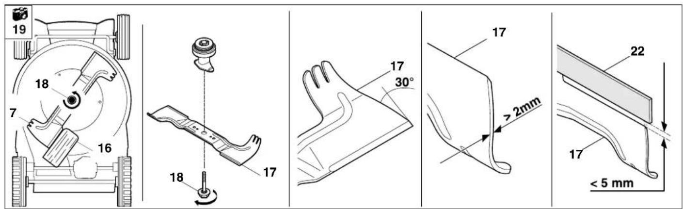
Wear limits:
The blade thickness must be at least 2 m m at any point. (Check using slide calliper).
The blades may not be ground back by more than 5 m m during sharpening.
When inspecting, place a 22= ruler against the front blade edge and check for wear.
CAUTION
If the supplied standard blade is not installed in the lawn mower, but e.g. the mulching blade, which is available as a special accessory, different wear limits apply.
CAUTION
Risk of injury!
A worn blade may break off and cause serious injuries. The instructions for blade maintenance must therefore always be observed.
Blades are subjected to differing degrees of wear depending on the location and duration of use. If you use the mower on sandy ground or use it frequently under dry conditions, the blade will be subjected to greater loads and will wear more quickly than the average.
Always replace the blade fastening screw (18) when replacing the mowing blade.

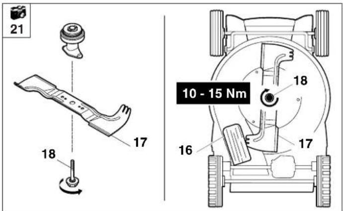
Removing the mowing blade

Risk of injury! Always wear gloves.
For removal, use a
16= wooden block (approx. 60 x 60 mm) to counterhold the
17= mowing blade. Unscrew the
18= blade fastening screw using an A/F 24 spanner. Remove the
17= mowing blade.
Sharpening the mowing blade
The following points must be observed when re-sharpening the mowing blade:
- Cool the mowing blade when sharpening, e.g. with water. The blade must not be allowed to display blue colouring, as this would reduce its cutting quality.
- Sharpen blades evenly to prevent vibration due to imbalance.

CAUTION
Risk of injury!
Check blade for damage before installing. The blade must be replaced if notches or cracks are identified, if the blades are worn back by 5 mm, or if the blade is thinner than 2 mm at any point (wear limits).
The sharpening angle of the blade is 30^ .
Checking the balance of the mowing blade


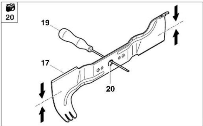
Guide the
19= screwdriver through the 20= central bore of the
17= mowing blade and align the blade horizontally. If the mowing blade is properly balanced it will remain in this horizontal position.
- If the blade leans to one side, re-sharpen this side until the blade is evenly balanced.
Installing the mowing blade

Adjusting the wheel drive cable


Risk of injury! Always wear gloves.
Install the
17= mowing blade with the curved wings pointing upwards.
For installation, use a
16= wooden block (approx. 60 x 60 mm) to counterhold the mowing blade.
Tighten the
18= blade fastening screw to a torque of 10 - 15 Nm.
CAUTION

Risk of injury!
Observe the specified torque of 10 - 15 Nm when tightening the blade fastening screws, as the secure attachment of the cutting tool depends on this. Additionally secure the blade fastening screw (18) with Loctite 243.
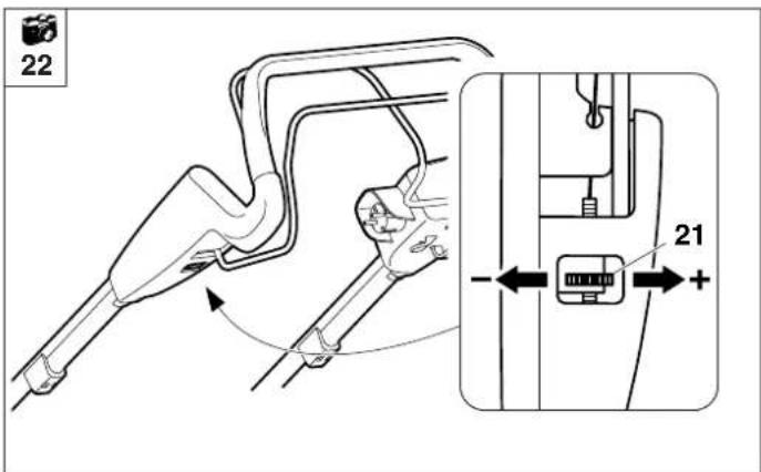
Maintenance interval: As required (wheel drive does not engage when the wheel drive lever is actuated)
The tension of the cable is adjusted correctly at the factory. However, the cable may have to be adjusted again following an extended period of use.
The adjustment is made via an
21= adjustment screw located on the left of the upper handlebar.
Correct adjustment:
Actuate the drive lever while pulling the lawn mower backwards.
The driving wheels must lock after approx. one third of the lever travel.
The cable tension is increased by turning the 21= adjustment screw in the “+” direction, turning it in the “-” direction reduces the tension.
CAUTION

Risk of injury!
If, when pulling back, the driving wheels are locked when the drive lever is not actuated, the cable is adjusted incorrectly and the mower drive is permanently activated.
As a result, the mower may start to move unintentionally immediately when started and this may result in injury or damage to the appliance.
The adjustment must be repeated (if necessary, contact a specialist dealer; VIKING recommends VIKING specialist dealers).
Storage (winter break)
The storage room should be dry and free of dust. The mower should also be stored out of reach of children.
Any appliance faults must be remedied prior to storage in order to maintain a safe operating condition.
Note the following points when storing the mower for long periods (winter break):
- Carefully clean all external parts of the appliance.
- Thoroughly lubricate/grease all moving parts.
Environmental protection
Lawn cuttings should be composted and not disposed of in household waste.
The appliance, its packaging and accessories are all produced from recyclable materials and must be disposed of accordingly.
By disposing of materials separately, and in an environmentally-friendly manner, valuable resources can be re-used. For this reason, the appliance should be disposed of for recycling after completion of its useful life.
Standard spare parts
Mowing blade 6340 702 0100
NOTE
i
The fastening elements of the mowing blade (e.g. blade fastening screw, lock washer) must be replaced when replacing the blade or when installing the blade. Spare parts are available from a VIKING specialist dealer.
Minimising wear and preventing damage
Important information on maintenance and care of the product group
Electric lawn mowers
Please always observe the following important information for the prevention of damage or excessive wear to your VIKING appliance:
1. Wearing parts
Some parts of the VIKING appliance are subject to normal wear even when used properly and must be replaced in due time depending on type and duration of use.
These include:
- Blade
- Grass catcher bag
- Protection bumpers
- V-belt (ME 545 V)
2. Observance of the information in this instruction manual
The VIKING appliance must be used, maintained and stored with the care described in this instruction manual. Any damage caused by non-observance of the safety, operating and maintenance instructions is the sole responsibility of the user.
This applies in particular to:
- inadequately dimensioned power cords (cross section)
- incorrect electrical connection (voltage)
- product modifications not approved by VIKING
- the use of tools or accessories which are not approved or suitable for the appliance, or are of inferior quality.
- improper use of the product
- use of the product for sporting or competitive events
- resultant damage due to continued use of the product with defective components
3. Maintenance operations
All work listed in the section "Maintenance" must be performed regularly. If these maintenance operations cannot be carried out by the user himself, a specialist dealer must be commissioned to do it.
VIKING recommends that you have maintenance operations and repairs performed exclusively by a VIKING specialist dealer.
VIKING specialist dealers regularly attend training courses and are provided with technical information.
If these operations are neglected, faults may arise which are the responsibility of the user.
These include:
- damage to the drive motor as a result of inadequate cleaning of the cooling air guide (inlet slots)
- corrosive and other resultant damage caused by incorrect storage
- damage to the appliance through the use of inferior-quality spare parts.
- damage due to untimely or inadequate maintenance or damage due to maintenance or repair work not performed in the workshops of specialist dealers.
Troubleshooting
| Fault Possible cause | Remedy Page Illustration | |||
| - Motor will not start | - No mains voltage- Connection cable/plug or plug connector or switch defective- Start button not pressed- Thermal motor overload protection has been triggered- Mower housing is blocked | - Check fuse- Check, replace if necessary- Press start button- Allow appliance to cool, then try again to start- Clean mower housing (disconnect mains plug before cleaning) | 9×10⁸, 9, ×11 | 1116 |
| - Frequently tripped mains fuse | - Unsuitable connection cord- Power overload- Appliance is overloaded due to mowing grass which is too long or too wet | - Use suitable connection cord- Connect the appliance to another circuit- Work at appropriate cutting height and mowing speed for mowing conditions | 997, 9 | 7 |
| - Excessive vibration during operation | - Blade fastening screw is loose- Motor mounting is loose- Blade imbalance due to incorrect re-sharpening or fracture | - Tighten blade fastening screw- Tighten motor fastening bolts- Re-sharpen (balance) or replace blade | 12, ××12, × | 1918, 19 |
| - No response when wheel drive lever is actuated (on ME 545 V) | - Wheel drive cable incorrectly adjusted- V-belt worn- Wheel drive cable damaged (e.g. kinked)- Gearbox is defective | - Re-adjust wheel drive cable- Replace V-belt- Replace wheel drive cable- Replace gearbox | 13××× | 20 |
see motor instruction manual
If necessary, contact a specialist dealer; VIKING recommends VIKING specialist dealers.
| Fault Possible cause | Remedy Page Illustration | |||
| - Vario drive speed control not functioning (on ME 545 V) | - Lever moved in wrong direction- Vario drive cable disengaged or damaged | - Move lever in right direction- Attach or replace vario drive cable | 10✘ | 13 |
| - Poor cut, lawn turning yellow | - Mowing blade is blunt or worn- The rate of feed is too high in relation to the cutting height | - Re-sharpen or replace mowing blade- Reduce rate of feed and/or select correct cutting height | 12,✘7 | 197 |
| - Starting problems or deteriorating motor performance | - Mowing grass which is too long or too wet- Mower housing is blocked | - Work at appropriate cutting height and mowing speed for mowing conditions- Clean mower housing (disconnect mains plug before cleaning) | 711 | 716 |
| - Ejection chute blocked | - Mowing blade is worn- Mowing grass that is too long or too wet | - Replace the mowing blade- Work at appropriate cutting height and mowing speed for mowing conditions | 12,✘7 | 197 |
see motor instruction manual
If necessary, contact a specialist dealer; VIKING recommends VIKING specialist dealers.
Technical specifications
| Unit ME 545.1 ME 545.0 V | ME 545.0 C | ||
| Serial number 6340 6340 | |||
| Motor, design Electric motor Electric motor | |||
| Manufacturer ATB ATB | |||
| TypeBSRBF 0,75/2-C74 BSRBF 0,75/2-C74 | |||
| Voltage Volt [V~] 230 | 230 | ||
| Power input | Watt [W] 1600 1600 | ||
| Fuse | Ampere [A] | 10 | 10 |
| Frequency | Hertz [Hz] | 50 | 50 |
| Protection class | II | II | |
| Type of protection | IPX 4 | IPX 4 | |
| Cutting utilities | Cutter bar | Cutter bar | |
| Cutting width | cm | 43 | 43 |
| Speed of cutting utilities | rpm | 2800 | 2800 |
| Cutter bar drive: | permanent | permanent | |
| In accordance with Guideline 2000/14/EC: | |||
| Guaranteed sound power level L_WAd | dB(A) | 94 | 94 |
| In accordance with Guideline 2006/42/EC: | |||
| Sound pressure level at workplace L_pA | dB(A) | 78 | 78 |
| Uncertainty K_pA | dB(A) | 1 | 1 |
| Specified vibration characteristic in accordance with EN 12096: | |||
| measured value a_hw | m/sec ^2 | 5,20 5,20 | |
| Uncertainty K_hw | m/sec ^2 | 2,08 2,08 | |
| Measurement in accordance with EN 20 643 | |||
| Tightening torque for blade fastening screw | Nm | 10 - 15 | 10 - 15 |
| Wheel drive, rear wheel | - | Vario | |
| Wheel diameter (front) | mm | 180 | 180 |
| Wheel diameter (rear) | mm | 200 | 200 |
| Cutting height | mm | 25 - 80 | 25 - 80 |
| Grass catcher bag | l | 60 | 60 |
| L/W/H | cm | 147x48x102 | 147x48x102 |
| Weight | kg | 26 / 30 | 32 |
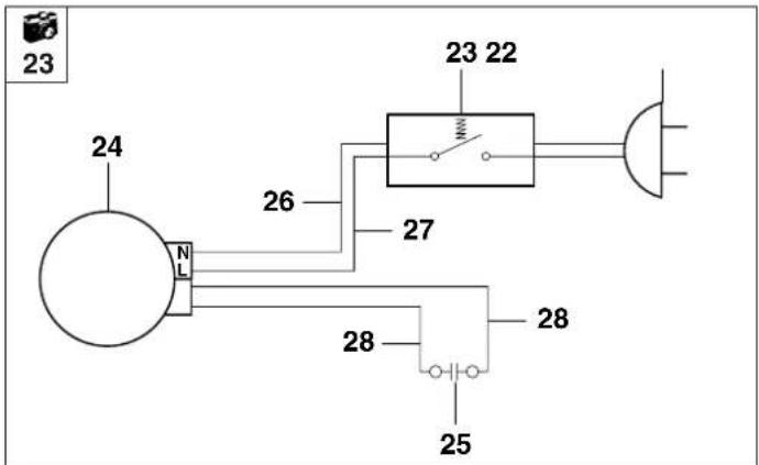
Circuit diagram

22 Mains connection
23 On/off switch
24 Motor
25 Capacitor
26 blue
27 brown
28 black
Description of symbols (2)
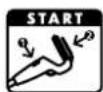
Start the engine
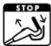
Stop the engine
ME 545 V
Switch on the wheel drive
CE - Manufacturer's declaration of conformity
We,
VIKING GmbH
declare, that the machine,
Lawn mower, manually-operated and mains-powered
Manufacturer's
brand: VIKING
Type: ME 545.1
ME 545.0 C
ME 545.0 V
Serial number: 6340
conforms to the following EU guidelines:
2000/14/EC, 2002/95/EC,
2002/96/EC, 2004/108/EC,
2006/95/EC, 2006/42/EC
The product has been developed in conformance with the following standards:
EN 60335-1,
EN 60335-2-77
Applicable conformity
assessment
procedure:
Appendix VIII (2000/14/EC)
Name and address of relevant, named location:
TÜV Rheinland LGA Products GmbH
Tillystraße 2
D-90431 Nürnberg
Compilation and storage of technical documentation:
Johann Weiglhofer
VIKING GmbH
Measured sound power level: 92 dB(A)
Guaranteed sound power level:
94 dB(A)
The year of manufacture and serial number appear on the identification plate of the machine.
Langkampfen,
02.01.2013
VIKING GmbH
Weiglhofer
Research and Product
Development Manager
Transport

Always wear gloves in order to prevent injuries
due to sharp-edged and hot components.
- Switch off the mower prior to transport, disconnect power cable and allow the blade to come to a stop.
- Only transport the appliance once the motor has cooled down.
• The mower must always be carried by two persons. - Use suitable loading aids (loading ramps, lifters).
- Secure the appliance on the load floor using adequately-dimensioned fastening material (belts, ropes etc.).
- When transporting the machine, always observe regional legislation, especially regarding load security and the transport of objects on load floors.
Service schedule
Please give this instruction manual to your VIKING specialist dealer when you have maintenance work performed on your VIKING product.
Your VIKING specialist will confirm the correct performance of the required service operations in the "Service schedule" section.
Model: ME ____ ____ ____
Serial number:

Handed over
Date: ____ ____ ____ ____

Next service
Date: ____ ____ ____ ____
Date: ____ ____ ____ ____

Next service
Date: ____ ____ ____ ____ ____
Date: ____ ____ ____ ____ ____

Next service
Date: ____ ____ ____ ____
Date: ____ ____ ____ ____

Next service
Date: ____ ____ ____ ____
Date: ____ ____ ____ ____

Next service
Date: ____ ____ ____ ____ ____
Date: ____ ____ ____ ____ ____

Next service
Date: ____ ____ ____ ____ ____
Date: ____ ____ ____ ____

Next service
Date: ____ ____ ____ ____ ____
Chère cliente, cher client,
2002/96/EC, 2004/108/EC,
2006/95/EC, 2006/42/EC
Het product is in
2002/96/EC, 2004/108/EC,
2006/95/EC, 2006/42/EC
2002/96/EC, 2004/108/EC,
2006/95/EC, 2006/42/EC
El producto ha sido
Koble inn fremdriften 10
Koble ut fremdriften 11
Nivåindikator 11
R= Hendel for motorstopp
S= Startknapp
T= Fremdriftshendel ME 545 V
U= Hendel for Vario-drift ME 545 V
2002/96/EC, 2004/108/EC,
2006/95/EC, 2006/42/EC
2002/96/EC, 2004/108/EC,
2006/95/EC, 2006/42/EC
Risiko for at snuble!
2002/96/EC, 2004/108/EC,
2006/95/EC, 2006/42/EC
2002/96/EC, 2004/108/EC,
2006/95/EC, 2006/42/EC
2002/96/EC, 2004/108/EC,
2006/95/EC, 2006/42/EC
2002/96/EC, 2004/108/EC,
2006/95/EC, 2006/42/EC
natural_image
Black-and-white photo of various lawn and lawn tools including lawn covers, grassing machines, and lawn cutters (no visible text or labels)
0478 121 9909 E