USER MANUAL SP 36 STIGA
natural_image
Illustration of hands operating a manual lawn tool on grass (no text or symbols)

Gentile Cliente,
COMANDI E RIFORNIMENTI
natural_image
Icon of a person reading a book inside a circle (no text or symbols)

natural_image
Black and white icon of a person wearing a helmet and sunglasses, enclosed in a circle (no text or symbols)
thank you for choosing one of our products. We hope that you will be completely satisfied with this machine and that it fully meets your expectations. This manual has been compiled in order to provide you with all the information you need to get acquainted with the machine and use it safely and efficiently. Don't forget that it is an integral part of the machine, so keep it handy so that it can be consulted when necessary, and pass it on to a further user if you resell or loan the machine.
Your new machine has been designed and manufactured in pursuance with current regulations, and is safe and reliable if used in compliance with the instructions provided in this manual (proper use). Using the machine in any other way, or non-compliance with the safety specifications relative to use, maintenance and repair is considered "improper use" which will invalidate the warranty, relieve the manufacturer from all liabilities, and the user will consequently be liable for all and any damage or injury to himself or others.
Since improvements are periodically made to our products, you may find slight differences between your machine and the descriptions contained in this manual. Certain modifications can be made to the machine without prior warning and without the obligation to update the manual, although the essential safety and function characteristics will remain unaltered. In case of any doubts, please contact your dealer. And now enjoy your work!
CONTENTS
- Identification of the main components ...... 2
- Symbols.... 3
- Safety requirements.... 4
- Machine assembly....7
- Preparing to work....8
- How to start - Use - Stop the engine.... 10
- Using the machine.... 11
- Maintenance and storage 13
- Identification of faults 17
- Accessories.... 18
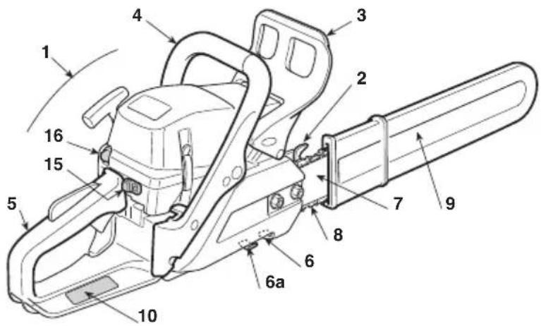
1. IDENTIFICATION OF MAIN COMPONENTS
MAIN COMPONENTS
- Power unit
- Spiked bumper
- Front hand guard
- Front handgrip
- Rear handgrip
- Chain catcher
6a. Chain catcher (only for mod. 46/52)
- Bar
- Chain
- Bar cover
- Identification plate
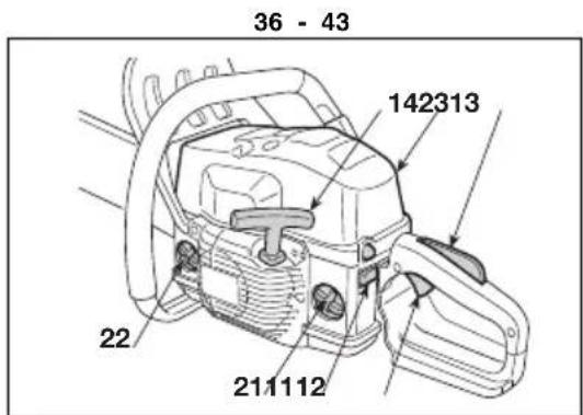
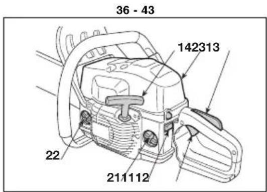
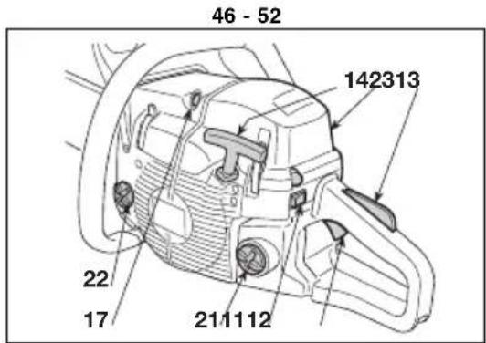
CONTROLS AND FILLING POINTS
- Engine stop switch
- Throttle trigger
- Throttle trigger lockout
- Starter
- Choke
- Primer
-
Decompression valve (only for mod. 46/52)
-
Fuel tank cap
- Chain oil tank cap
- Air cleaner cover

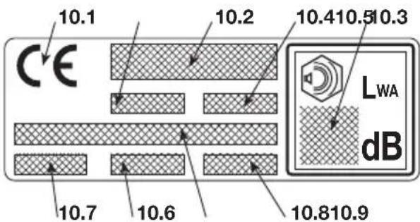
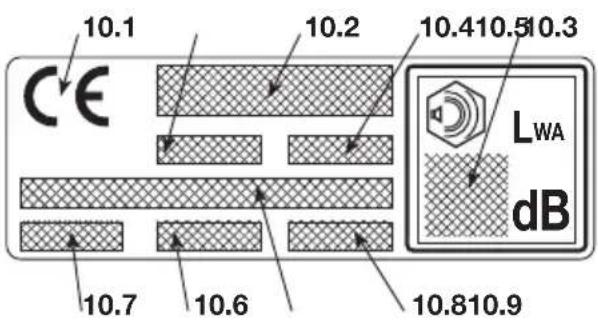
IDENTIFICATION PLATE
10.1) Conformity marking in accordance with Directive 2006/42/EC
10.2) Name and address of the manufacturer
10.3) Acoustic output level LWA in accordance with directive 2000/14/EC
10.4) Manufacturer's model of reference
10.5) Machine model
10.6) Serial number
10.7) Year of manufacture
10.8) Article Code
10.9) Emission number
| Maximum noise and vibration level§1] | Model | 36 43 | 46 52 | | |
| Operator ear noise pressure level (ISO 22868) dB(A) 98,9 98,9 10 | 2,3 101,6 | | | | |
| - Measurement uncertainty (2006/42/EC - EN 27574) | dB(A) | 2,5 | 2,5 | 2,5 | 2,5 |
| Measured acoustic output level (ISO 22868) | dB(A) | 108,1 108,1 | 113 | 113,4 | |
| - Measurement uncertainty (2006/42/EC - EN 27574) | dB(A) | 2,5 | 2,5 | 2,5 | 2,5 |
| Vibration level (ISO 22867) | m/sec ^2 | 7,5 - 6,2 | 7,5 - 6,2 | 4,9 - 3,6 | 5,7 - 4,9 |
| - Measurement uncertainty (2006/42/EC - EN 12096) | m/sec ^2 | 0,5 | 0,5 | 0,5 | 0,5 |
| TECHNICAL SPECIFICATIONS |
| Engine (2-stroke single cylinder) – displacement | cm ^3 | 36,3 40,2 | 45 | 52 | |
| Fuel (petrol/oil) | % | 50:1 = 2 % | 50:1 = 2 % | 50:1 = 2 % | 50:1 = 2 % |
| Power | kW | 1,5 | 2,0 | 2,2 | 2,4 |
| Idle RPM | 1min | 2800 ± 150 | 2800 ± 150 | 2800 ± 150 | 2800 ± 150 |
| Maximum admissible rpm without load with chain installed | 1min | 11300 | 12000 | 12500 | 12500 |
| Fuel tank capacity | cm ^3 | 370 | 370 | 500 | 500 |
| Maximum power specific consumption | g/kWh | 490 | 410 | 510 | 500 |
| Oil tank capacity | cm ^3 | 190 | 190 | 300 | 300 |
| Chain pinion teeth | | 6 | 7 | 7 | 7 |
| Weight (with empty tank) | kg | 4,2 | 4,1 | 4,7 | 4,7 |
[1] WARNING! The vibration value may vary according to the usage of the machine and its fitted equipment, and be higher than the one indicated. Safety measures must be established to protect the user and must be based on the load estimate generated by the vibrations in real usage conditions. In this regard, all the operational cycle phases must be taken into consideration, such as switching off or idle running.
2. SYMBOLS

natural_image
Icon of a person reading a book inside a circle (no text or symbols)

natural_image
Black and white icon of a person wearing a helmet and sunglasses, enclosed in a circle (no text or symbols)
1) Read the instruction manual before using the machine.
2) If you are using the machine every day in normal conditions, you can be exposed to a noise level of 85 dB (A) or higher. Wear a protective helmet, ear plugs and goggles.
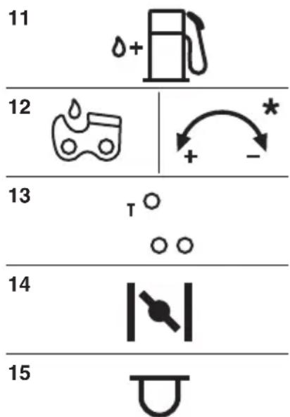
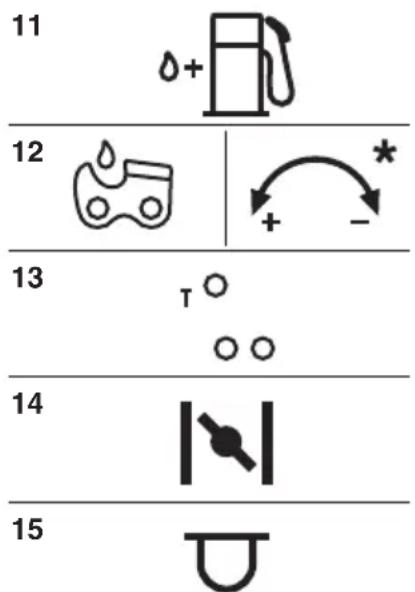
EXPLANATORY SYMBOLS ON THE MACHINE (if present)
11

12


13
T ^0
○○
14

15

11) Fuel tank
12) Chain oil tank and oil flow adjuster (only for mod. 46/52)
13) Carburettor adjustments
T = idle speed adjuster
(L) = low speed mixture adjuster
(H) = high speed mixture adjuster
14) Choke
15) Primer
3. SAFETY REQUIREMENTS
A) TRAINING
1) Read the instructions carefully. Become acquainted with the controls and the proper use of the machine. Learn how to stop the engine quickly.
2) Only use the machine for the purpose for which it was designed, that is for "felling, bucking and delimbing trees with dimensions suitable for the length of the bar" or wooden objects with the same characteristics. Any other use may be dangerous and damage the machine.
Examples of improper use may include, but are not limited to:
- trimming hedges;
- intaglio carving;
– sectioning pallets, crates and various packing materials;
– sectioning furniture or other materials with nails, screws or other metal components;
– butchering meat;
- using the machine to lift, move or split objects;
– using the machine while fastened to fixed supports.
3) Never allow children or persons unfamiliar with these instructions to use the machine. Local regulations may restrict the age of the operator.
4) The machine must never be used by more than one person.
5) Never use the machine:
– when people, especially children or pets are in the vicinity;
– f the user is tired or unwell, or has taken medicine, drugs, alcohol or any substances which may slow his reflexes and compromise his judgement;
- if the user is not capable of holding the machine firmly with two hands and/or remaining standing on the ground whilst working.
6) Remember that the operator or user is responsible for accidents or hazards occurring to other people or their property.
B) PREPARATION
1) Always wear adequate clothing which does not hamper movements when using the machine.
- Always wear slim-fitting protective clothing, fitted with shear-proof protection devices.
- Always wear a helmet, protective gloves, eye-goggles, a half-mask respirator and safety anti-shear boots with non-slip soles.
– Always wear ear and hearing protection devices.
- Never wear scarves, shirts, necklaces, or any hanging or flapping accessory that could catch in the machine or in any objects or materials in the work area
- Tie your hair back if it is long.
2) WARNING: DANGER! Fuel is highly flammable:
- keep the fuel in containers which have been specifically manufactured and homologated for such use;
– never smoke when handling fuel;
– slowly open the fuel tank to allow the pressure inside to decrease gradually;
– top up the tank with fuel in the open air, using a funnel;
- add fuel before starting the engine. Never remove the fuel tank cap or add fuel while the engine is running or when the engine is hot;
- if you have spilt some fuel, do not attempt to start the engine but move the machine away from the area of spillage and avoid creating any source of ignition until the fuel has evaporated and fuel vapours have dissipated;
– immediately clean up all traces of fuel spilt on the machine or on the ground;
– never start the machine in the same place you refilled it with fuel;
- make sure your clothing does not come into contact with the fuel, on the contrary, change your clothes before starting the engine;
– always put the tank and fuel container caps back on and tighten well.
3) Replace faulty or damaged silencers.
4) Before using the machine, check its general condition and in particular:
– the throttle trigger and the safety lever must move freely, they must not need forcing and should return automatically and rapidly back to the neutral position;
- the throttle trigger must remain locked until the safety lever is pressed;
- the engine stop switch must easily move from one position to the other;
- the electric cables and in particular the spark plug cable must be in perfect condition to avoid the generation of any sparks, and the cap must be correctly fitted on the spark plug;
– the machine handgrips and protection devices must be clean and dry and well fastened to the machine;
– the chain brake must be in perfect working order;
– the bar and the chain must be fitted correctly;
– the chain must be tensioned correctly.
5) Before starting your work, make sure that all the protection devices are correctly fitted.
C) OPERATION
1) Do not operate the engine in a confined space where dangerous carbon monoxide fumes can collect. Make sure air circulates when working in pits, holes or similar.
2) Work only in daylight or good artificial light.
3) Take on a firm and well-balanced position:
- where possible, avoid working on wet, slippery ground or in any case on uneven or steep ground that does not guarantee stability for the operator;
- avoid using unstable ladders or platforms;
– do not work with the machine above your shoulders;
– never run, but walk carefully paying attention to the lay
of the land and any eventual obstacles.
- avoid working alone or in an isolated place, in case you have to find help after an accident.
4) Make sure the machine is securely locked when you start the engine:
- start the motor in an area at least 3 metres from where you refuelled;
– check that there are no persons in the vicinity of the machine;
– do not direct the silencer and therefore the exhaust fumes towards inflammable materials.
– watch out for flying debris caused by the movement of the chain, especially when it hits obstacles or foreign objects.
5) Do not change the engine tuning and do not rev the engine excessively at maximum speed.
6) Do not strain the machine too much and do not use a small chain-saw for heavy-duty sawing. If you use the right machine, you will reduce the risk of hazards and improve the quality of your work.
7) Check that when the machine is running idle, there is no movement of the chain and, after pressing the throttle trigger, the engine quickly returns to minimum speed.
8) Take care not to hit the bar hard against foreign objects or flying debris caused by the movement of the chain.
9) Stop the engine:
– whenever you leave the machine unattended;
– before refuelling.
10) Stop the engine and disconnect the spark pl
cable:
– before cleaning, checking or working on the machine;
– after striking a foreign object. Inspect the machine for any damage and make repairs before restarting it again;
- if the machine begins to abnormally vibrate (Immediate look for the cause of the vibrations and take for necessary controls at a Specialised Centre).
– when the machine is not in use.
11) Avoid exposure to dust and sawdust produced by the chain when cutting.
1) Keep all nuts, bolts and screws tightly fastened to be sure the equipment is in safe working condition. Routine maintenance is essential for safety and for maintaining a high performance level.
2) Do not store the machine with fuel in the tank in an area where the fuel vapours could reach an open flame, a spark or a strong heat source.
3) Allow the engine to cool before storing in any enclosure.
4) To reduce fire hazards, keep the engine, exhaust silencer and fuel storage area free from sawdust, branches, leaves, or excessive grease; never leave containers with the cut debris inside the storage area.
6) If the fuel tank has to be emptied, this should
done outdoors once the engine has cooled down.
7) Make sure the chain is well sharpened. Any work on the chain and bar require specific experience and special tools. For safety purposes, we recommend you contact your dealer to ensure work is done correctly.
8) For safety reasons, never use the machine with worn or damaged parts. Damaged parts are to be replaced and never repaired. Only use original spare parts. Parts that are not of the same quality can seriously damage the equipment and compromise safety.
9) Before putting the machine away, check you have removed wrenches or tools used for maintenance.
10) Store the machine out of the reach of children!
E) TRANSPORTATION AND HANDLING
1) Whenever the machine is to be handled or transported you must:
- turn off the engine, wait for the chain to stop and disconnect the spark plug cap;
- mount the bar cover;
- only hold the machine using the handgrips and position the bar in the opposite direction to that used during operation.
2) When using a vehicle to transport the machine, position it so that it can cause no danger to persons and fasten it firmly in place to avoid it from tipping over, which may cause damage or fuel spillage.
F) CHAIN SAW SAFETY WARNINGS:
- Keep all parts of the body away from the saw chain when the chain saw is operating. Before you start the chain saw, make sure the saw chain is not contacting anything. A moment of inattention while operating chain saws may cause entanglement of your clothing or body with the saw chain.
- Always hold the chain saw with your right hand on the rear handle and your left hand on the front handle. Holding the chain saw with a reversed hand configuration increases the risk of personal injury and should never be done.
- Wear safety glasses and hearing protection. Further protective equipment for head, hands, legs and feet is recommended. Adequate protective clothing will reduce personal injury by flying debris or accidental contact with the saw chain.
- Do not operate a chain saw in a tree. Operation of a chain saw while up in a tree may result in personal injury.
- Always keep proper footing and operate the chain saw only when standing on fixed, secure and level surface. Slippery or unstable surfaces such as ladders may cause a loss of balance or control of the chain saw.
- When cutting a limb that is under tension be alert for spring back. When the tension in the wood befibres is released the spring loaded limb may strike the
operator and/or throw the chain saw out of control.
- Use extreme caution when cutting brush and saplings. The slender material may catch the saw chain and be whipped toward you or pull you off balance.
- Carry the chain saw by the front handle with the chain saw switched off and away from your body. When transporting or storing the chain saw always fit the guide bar cover. Proper handling of the chain saw will reduce the likelihood of accidental contact with the moving saw chain.
- Follow instructions for lubricating, chain tensioning and changing accessories. Improperly tensioned or lubricated chain may either break or increase the chance for kickback.
- Keep handles dry, clean, and free from oil and grease. Greasy, oily handles are slippery causing loss of control.
- Cut wood only. Do not use chain saw for purposes not intended. For example: do not use chain saw for cutting plastic, masonry or non-wood building materials. Use of the chain saw for operations different than intended could result in a hazardous situation.
G) CAUSES AND OPERATOR PREVENTION OF KICKBACK:
Kickback may occur when the nose or tip of the guide bar touches an object, or when the wood closes in and pinches the saw chain in the cut.
Tip contact in some cases may cause a sudden reverse reaction, kicking the guide bar up and back towards the operator.
Pinching the saw chain along the top of the guide bar may push the guide bar rapidly back towards the operator.
Either of these reactions may cause you to loose control of the saw which could result in serious personal injury. Do not rely exclusively upon the safety devices built into your saw.
As a chain saw user, you should take several steps to keep your cutting jobs free from accident or injury.
Kickback is the result of tool misuse and/or incorrect operating procedures or conditions and can be avoided by taking proper precautions as given below:
by the manufacturer. Incorrect replacement bars and chains may cause chain breakage and/or kick-back.
- Follow the manufacturer's sharpening and maintenance instructions for the saw chain. Decreasing the depth gauge height can lead to increased dy.kickback.
H) CHAIN-SAW OPERATING TECHNIQUES
Always observe the safety regulations and use the most suitable sawing techniques (see chapter 7 for instructions and examples).
J) RECOMMENDATION FOR THE FIRST-TIME USERS
Before felling or delimbing for the first time, make sure:
- you have been specifically trained to use this type of equipment;
– you have carefully read the safety regulations and user instructions contained in this manual;
- you practise first on logs on the ground or attached to trestles, in order to get familiar with the machine and the most suitable cutting techniques.
K) HOW TO READ THE MANUAL
Certain paragraphs in the manual contain particularly significant information and are marked with various levels of highlighting with the following meaning:
NOTE
or
IMPORTANT
These give details or further in-
formation on what has already been indicated, and aim to prevent both damage to the machine, and the machine from causing damage.

WARNING!
Non-observance will result
in the risk of injury to oneself or others.

DANGER!
Non-observance will result
in the risk of serious injury or death to oneself or
- Maintain a firm grip, with thumbs and fingers en-others.
circling the chain saw handles, with both hands on the saw and position your body and arm to allow you to resist kickback forces. Kickback forces can be controlled by the operator, if proper precautions are taken. Do not let go of the chain saw.
- Do not overreach and do not cut above shoulder height. This helps prevent unintended tip contact and enables better control of the chain saw in unexpected situations.
- Only use replacement bars and chains specified
4. MACHINE ASSEMBLY
IMPORTANT
The machine is supplied with the bar and chain dismantled and the oil and fuel tanks empty.

WARNING!
Unpacking and completing the assembly should be done on a flat and stable surface, with enough space for machine handling and its packaging, always making use of suitable equipment.
- Disposal of the packaging should be done in accordance with the local regulations in force.

WARNING!
Always wear heavy-duty
dling the bar and chain. Mount the bar and chain very carefully so as not to impair the safety and efficiency of the machine. If in doubt, contact your dealer.
Before fitting the bar, make sure the chain brake is not engaged; this is done by pulling the front hand guard right back towards the body of the machine.

WARNING!
Perform all operations
with the engine off.
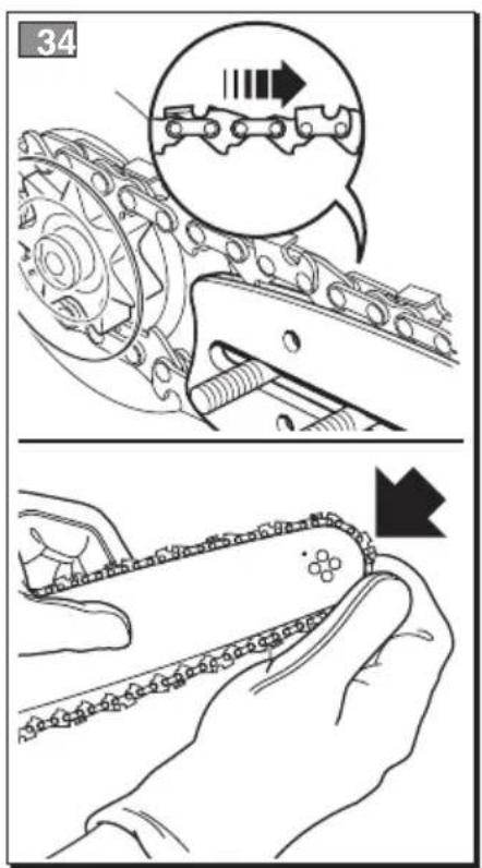
- Mount the bar (4) by inserting the stud bolts in the groove and push it towards the back of the machine body (Fig. 2).
- Mount the chain in the right direction around the drive sprocket and along the bar rail (Fig. 3). If the tip of the bar has a nose sprocket, make nd sure the drive links fit correctly in the sprocket rims.
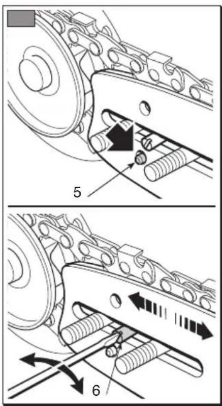
- Check that the chain tension adjuster pin (5) is fitted properly in the hole on the bar; if it isn't, turn the chain tension adjuster screw (6) using a screwdriver until the pin is completely inserted (Fig. 4).
- Fit the guard back on without tightening the nuts.
- Turn the chain tension adjuster screw (6) to adjust the chain tension (Fig. 5).
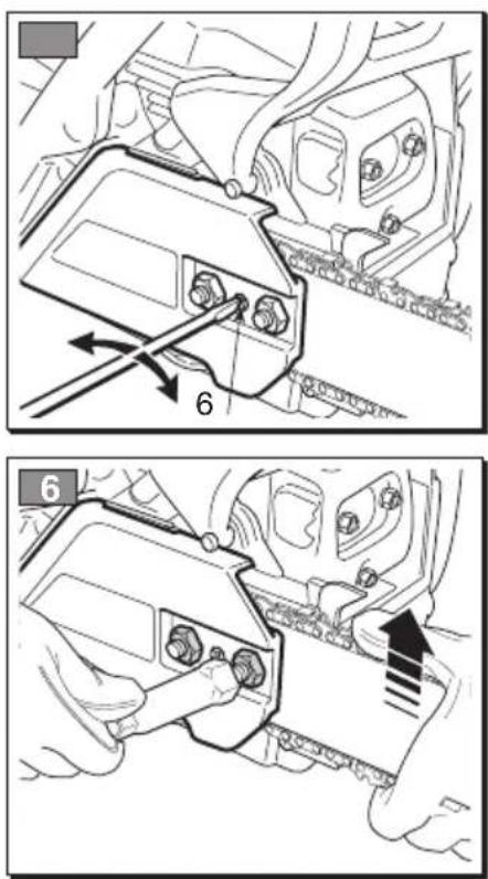
- Raise the bar and tighten the guard nuts securely using the wrench (Fig. 6).
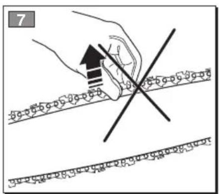
- Check the chain tension. The tension is correct when the drive links do not slip out of the chain guides if you hold the chain in the middle of the bar (Fig. 7).
- Using a screwdriver, make the chain run along the guides to check it moves smoothly without resistance.
1. SPIKED BUMPER ASSEMBLY (if not already factory assembled)
- Unscrew the nuts (1) and remove the clutch cover (2).
- Secure the spiked bumper (3) to the machine frame using the two supplied screws (4) (Fig. 1).
2. BAR AND CHAIN MOUNTING
- Unscrew the nuts and remove the clutch cover to get to the drive sprocket and point where the bar is to be fitted (Fig. 2).
- Remove the two cardboard spacers, (3); these spacers must be used exclusively when transporting the machine in its packaging and must not be used at any other time (Fig. 2).
5. PREPARING TO WORK
1. PREPARING THE FUEL
This machine is fitted with a two-stroke engine which requires a mixture of petrol and lubricating oil.
IMPORTANT
Using petrol alone will dam-
age the motor and will cause for invalidation of the warranty.
IMPORTANT
Only use quality fuels and
oils to maintain high performance and guarantee the duration of the mechanical parts over time.
• Petrol characteristics
Only use unleaded petrol with a fuel grade of at least 90 N.O.
IMPORTANT
Unleaded petrol tends to cre-
ate deposits in the container if preserved for more than 2 months. Always use fresh petrol!
- Oil characteristics
Only use top quality synthetic oil specifically for two-stroke engines.
Your dealer can provide you with oils which have been specifically developed for this type of engine, and which are capable of guaranteeing a high level of protection.
The use of these oils makes it possible to prepare a 2% mixture, consisting in 1 part oil to 50 parts petrol.
- Preparation and preservation of the fuel mixture

DANGER!
Petrol and the fuel mixture are highly inflammable!
- Keep the petrol and fuel mixture in homologated fuel containers, in safe place, away from any flames or heat sources.
- Never leave the containers within the reach of children.
- Never smoke whilst preparing the mixture and avoid inhaling the petrol fumes.
The chart indicates the amount of petrol and oil to use to prepare the fuel mixture according to the type of oil used.
| Petrol Synthetic oil 2-stroke |
| liters liters cm | 3 |
| 10,02 | 20 | |
| 20,04 | 40 | |
| 30,06 | 60 | |
| 50,10 | 100 | |
| 10 | 0,20 | 200 |
To prepare the fuel mixture:
- Place about half the amount of petrol in a homologated tank
- Add all the oil, according to the chart.
- Add the rest of the petrol.
- Close the top and shake well.
IMPORTANT
The fuel mixture tends to
age. Do not prepare excessive amounts of the fuel mixture to avoid deposits from forming.
IMPORTANT
Keep the petrol and fuel mix-
ture containers separate and easily identifiable to avoid the mistake of using one in place of the other.
IMPORTANT
Periodically clean the petrol
and fuel mixture containers to remove any eventual deposits.
2. REFUELLING

DANGER!
Never smoke whilst refu-
elling and avoid inhaling the petrol fumes.

DANGER!
Add fuel before starting
-the engine. Never remove the fuel tank cap or add fuel while the engine is running or when the engine is hot.

WARNING!
Carefully open the tank
top as pressure could have formed inside.
Before refuelling:
- Shake the fuel mixture container well.
- Place the machine on a flat stable surface, with the fuel tank cap facing upwards.
- Clean the fuel tank cap and the surrounding area to avoid any dirt from entering the tank during refilling.
- Carefully open the fuel tank cap to allow the pressure inside to decrease gradually. Use a funnel to refill and avoid filling the tank to the brim.
– check that the chain is sharp and there are no signs of any damage;
– check that the air filter is clean;
- check that handgrips and protection devices are clean and dry, correctly mounted and well fastened to the machine;
– check that the handgrips are well fastened;
– check that the chain brake is working efficiently;
– check the chain tension.
5. CHECKING THE CHAIN TENSION

WARNING!
cap firmly.
Always close the fuel tank

WARNING!
WARNING! Immediately clean all traces of fuel which may have dripped on the machine or the ground and do not start the gine until the petrol fumes have dissipated.

WARNING!
Perform all operations
with the engine off.
- Loosen the cover nuts, using the supplied wrench (Fig. 6).
en-Turn the chain tension adjuster screw (6) to adjust the chain tension (Fig. 5).
- Raise the bar and tighten the guard nuts securely using the wrench (Fig. 6).
3. CHAIN LUBRICANT
IMPORTANT
IMPORTANT Only use special oil for chain saws or adhesive oil for chain saws. Do not use oil containing impurities so as not to block the oil filter and to prevent irreparable damage to the oil pump.
IMPORTANT
IMPORTANT The special oil for lubricating the chain is biodegradable. Use of a mineral oil or engine oil causes serious damage to the environment.
It is essential that you use good quality oil to lubricate the cutting parts effectively. Used or poor quality oil does not guarantee good lubrication and reduces the duration of the chain and bar.
It is always worth topping up the oil tank completely (using a funnel) every time you refuel. Since the oil tank capacity is enough to guarantee that the fuel runs out first, you will avoid the risk of operating the machine without lubricant.
4. CHECKING THE MACHINE
Before starting work please:
– fill the relevant tanks with fuel and oil;
- check that all the screws on the machine and the bar are tightly fastened;
This machine is equipped with a safety brake system.
In the event of a kickback while working, following an irregular contact of the tip of the bar, with a brusque upward movement that causes the hand to strike the front guard. In this case, the brake blocks chain movement and must be released manually in order to disengage it.
This brake can be operated manually by pushing the front guard forward. To release the brake, pull the front guard towards the handgrip until you hear a click.
To check that the brake works efficiently, proceed as follows:
- Make sure you are holding the machine firmly with both hands when you start the engine
- Use the accelerator level to keep the chain moving, push the brake lever forwards using the back of you left hand; the chain must stop immediately.
- When the chain has stopped, immediately release the accelerator lever.
- Release the brake.

WARNING!
Do not use the machine if
the chain brake does not function correctly and have it inspected by your dealer.
6. HOW TO START - USE - STOP THE ENGINE
STARTING THE ENGINE
WARNING!
The engine must be started in an area at least 3 metres from where you refilled the fuel tank.
Before starting the engine:
- Place the machine firmly on the ground.
- Take off the bar cover.
- Make sure the bar is not touching the ground or any other object.
- Cold starting
NOTE
A "cold" start of the engine means starting it after at least 5 minutes from when it was switched off or after refuelling.
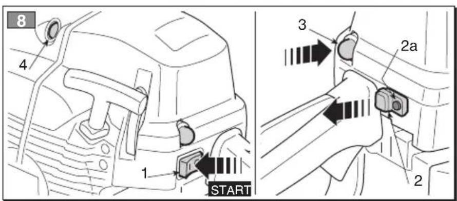
To start the engine (Fig. 8):
- Check that the chain brake is engaged (with the front hand guard pushed forward).
- Set the switch (1) to «START».
- Pull the knob (2) as far as possible to engage the starter.
- Press the primer device button (3) at least 5 times to prime the carburettor.
- Press the decompression valve button (4 - only for Mod. 46 and 52); the device turns off and the button automatically returns to its original position immediately after the engine starts.
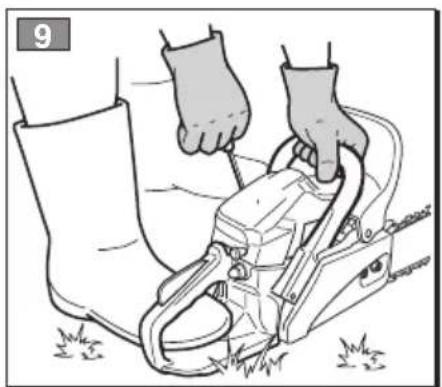
- Hold the machine firmly on the ground, with your hand on the handgrip and your foot in the rear handgrip, to avoid losing control during starting (Fig. 9).
DANGER!
Never start the chain saw by holding on to the starter cable and allowing it to fall. This is an extremely dangerous method as you lose complete control over the machine and the chain.
IMPORTANT
To avoid breaking the starter rope, do not pull the whole length of it or let it slide along the edge of the cable guide hole. Release the starter gradually, to avoid letting it fly back uncontrollably.
- Retract the starter knob (2); this condition is indicated by the protruding red pin (2a).
- Pull the starter rope again until the engine starts as normal.
NOTE
If the starter rope is pulled repeatedly with the choke on, it may flood the engine and make starting difficult. If you have flooded the engine, remove the spark plug and gently pull the handle on the starter rope to eliminate any excess fuel; then dry the spark plug electrodes and replace it on the engine.
- When the engine has started, press the throttle trigger to disconnect the starter and allow the engine to idle.
IMPORTANT
Do not let the engine run at high power with the chain brake engaged, as this could cause overheating and damage to the clutch.
- Let the engine run idle for at least 1 minute before using the machine.
- Hot starting
WARNING!
If the machine is not held firmly, the force of the engine could cause the user to lose his balance or direct the bar towards him or an obstacle.
- Pull the starter rope slowly for 10 - 15 cm until you feel some resistance, then tug it hard a few times until you hear the engine turn over.
WARNING!
Never wind the starter cable around your hand.
For hot start (immediately after turning off the engine) pulling the starting cord normally suffices.
In the event of difficulty:
– Pull the starter knob (2) fully out and push it back in so that the red pin (2a) protrudes.
– Pull the starter cord grip until the engine starts as normal.
- When the engine has started, press the throttle trigger to disconnect the starter and allow the engine to idle.
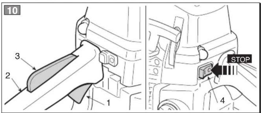
USE OF THE ENGINE (Fig. 10)
IMPORTANT
Always disengage the chain
brake, pulling the lever towards you before using the accelerator.
The chain speed is regulated by the throttle trigger (1) on the rear handgrip (2).
The throttle trigger only works if the lockout (3) is pressed at the same time.
The movement is transmitted from the engine to the chain by a centrifugal mass clutch that prevents the chain from moving when the engine is running at minimum speed.

WARNING!
Do not use the machine if the chain moves when the engine is running idle; in this case, contact your dealer.
The correct running speed will be achieved by pressing the throttle trigger (1) as far as possible.
IMPORTANT
Avoid using the engine at full power for the first 6-8 working hours.
STOPPING THE ENGINE (Fig. 10)
To stop the engine:
- Release the throttle trigger (1) and allow the engine to run idle for a few seconds.
- Set the switch (4) to "STOP".

WARNING!
When you have reduced speed to a minimum, it may take a few seconds for the chain to stop.
IMPORTANT
If the machine does not turn off, pull the starter to flood and stop the engine and immediately contact the dealer to find the cause of the problem and request necessary repairs.
7. USING THE MACHINE
IMPORTANT
Always remember that an incorrectly used chain-saw may disturb others and have a serious impact on the environment.
To respect people and the environment:
- Avoid using the machine in environments or at times of the day when it may disturb others.
- Scrupulously comply with local regulations and provisions for the disposal of waste materials after sawing.
- Scrupulously comply with local regulations and provisions for the disposal of oils, damaged parts or any elements which have a strong impact on the environment.
- A certain amount of chain lubricating oil is released into the environment when the machine is running, so only use biodegradable oils made specifically for this use.
- To avoid the risk of fire, do not leave the machine with the engine hot on leaves or dry grass.
the most suitable accident-prevention devices to guarantee your safety. Wear anti-vibration gloves. All the above-mentioned precautions do not however guarantee the prevention of certain risks - i.e. Raynaud's phenomenon or Carpal tunnel syndrome. For operators who use this machine for prolonged periods, it is therefore recommended to have periodic check-ups on the hands and fingers. If any of the above mentioned symptoms should appear, please contact a physician immediately.

DANGER!
This machine's starter unit generates an average sized electromagnetic field, but it is not however possible to exclude the possibility of interference on any active or passive medical devices that operators may be wearing; this could be risky for their health conditions. All those using medical devices should always consult their GP, or the device manufacturer, before using this machine.

WARNING!
Always wear suitable clothing when using the machine. Your dealer can provide you with all the information on

WARNING!
It takes specific training to use the machine for felling and delimbing.
1. CHECKS DURING WORK
- Checking the chain tension
The chain tends to stretch gradually as you work, so you need to check its tension frequently.
IMPORTANT
During the first period of use (or after replacing the chain), it must be checked more frequently due to settling of the chain.
WARNING! When running, the machine must always be firmly held in both hands, with the right hand on the front hand-grip and the left hand on the rear handgrip, even if the operator is left-handed.
WARNING! Stop the engine immediately if the chain stops during sawing. Beware of kickback, which can occur if the bar contacts an obstacle.

WARNING!
Never work with the chain loose, as it can be hazardous if the chain slips out of its guides.
To adjust the chain tension, follow the instructions in Chapter 5.5.
- Checking the oil delivery
IMPORTANT
Never use the machine without lubrication! The oil tank may get almost empty every time the fuel runs out. Make sure you top up the oil tank every time you refuel the chain-saw.
- Delimbing (Fig. 13)

WARNING!
Make sure there is nothing or nobody in the area where the branches will fall.
- Stand opposite the branch you want to cut.
- Start cutting lower branches followed by the higher ones.
- Cut downwards to prevent the bar from getting jammed.
• Felling (Fig. 14)

WARNING!
Make sure the bar and the chain are in place when you check the oil delivery.
Start the engine, keep it running at medium power and check if the chain oil is delivered as shown in the figure (Fig. 12).
Only for mod. 46 and 52
You can adjust the chain oil flow using a screw-driver on the adjuster screw (1) of the oiler, which is on the bottom of the machine (Fig. 12).
2. DIRECTIONS FOR USE AND CUTTING TECHNIQUES
Before felling or delimbing for the first time, practise sawing logs on the ground or on trestles, so that you can get familiar with the machine and the most suitable sawing techniques.

WARNING!
When felling on slopes, always stand uphill from the tree and check that the felled trunk cannot cause damage if it rolls down the hill.
- Decide where the tree should fall – you should consider the wind, the natural lean of the tree, the position of the heaviest branches and how easy the work is after felling, etc.
- Clear the area around the tree and find a stable place to stand.
- Plan obstacle-free escape routes at a 45^ angle back and away from the direction of fall. These routes must allow you reach a safe area at a distance of about 2.5 times the length of the tree to be felled
- On the side of the fall, mark a felling notch around a third of the trunk's diameter.
- Cut the tree on the other side, slightly above the bottom of the notch, leaving the uncut wood to act as a "hinge" (1) of approx. 5-10 cm.
- Reduce the thickness of this hinge without pulling out the bar, until the tree falls.
- In particular or unstable conditions, you can complete felling by inserting wedges (2) on the
opposite side of the fall, and hitting them with a hammer until the tree falls.
•Bucking (Fig. 15)

WARNING!
Be careful of where the branches are lying on the ground, the risk of them being under tension, the direction the branch may go during cutting and the risk of the tree being unstable after the branch has been cut.
- Check the direction in which the branch is attached to the tree
- First cut on the side where the branch bends and then finish cutting on the opposite side.
- Sawing logs (Fig. 16)
It is easier to saw a log using the spiked bumper.
- Dig the spiked bumper into the log and use it as a pivot. Cut with an arched motion to make the bar penetrate the wood.
- Repeat several times if necessary, changing the point where you plant the spiked bumper.
- Sawing a log on the ground (Fig. 17)
Cut up to half the diameter, roll the log over and finishing sawing on the other side.
- Sawing a raised log (Fig. 18)
- If you are sawing the overhanging end of a supported log (A), first cut a third of the diameter from the bottom upwards, then finish from the top.
-
If you are sawing between two supports (B), cut a third of the diameter from the top downwards, then finish from the bottom.
-
END OF OPERATIONS
When you have finished your work:
- Switch off the engine as indicated above (Chap. 6).
- Wait for the chain to stop and allow the machine to cool.
- Loosen the rod fastening nuts to reduce chain tension.
- Remove any traces of sawdust or oil deposits from the chain.
- If there is excessive dirt or resin build-up, disassemble the chain and place it in a container with a specific cleanser. Then rinse it with clean water and treat it with a suitable anticorrosive spray, before reassembling on the machine.
- Fit the bar cover before reassembling the machine.

WARNING!
Allow the engine to cool before storing in any enclosure.
To reduce fire hazards, clean the machine thoroughly to get rid of any sawdust, branches, leaves or excess grease, never leave containers with the cut debris inside the storage area.
8. MAINTENANCE AND STORAGE

WARNING!
For your safety and that
of others:
- Correct maintenance is essential to maintain the original efficiency and safety of the machine over time.
- Keep all nuts, bolts and screws tight to be sure the equipment is in safe working condition.
- Never use the machine with worn or damaged parts. Damaged parts are to be replaced and never repaired.
- Only use original spare parts. Parts that are not of the same quality can seriously damage the equipment and compromise safety.

WARNING!
During maintenance operations:
Remove the spark plug cap.
Wait until the engine is sufficiently cold.
Use protective gloves when handling the bar and chain.
Keep the bar protection devices on, except when intervening directly on the bar or the chain.
Never dispose of oils, fuel or other polluting materials in unauthorised places.
CYLINDER AND SILENCER (Fig. 19)
To reduce fire risks, periodically clean the cylinder flaps with compressed air and clear the silencer area to get rid of sawdust, branches, leaves or other debris.
STARTING SYSTEM
To avoid overheating and damage to the engine, always keep the cooling air vents clean and free of sawdust and debris.
The starter rope must be replaced as soon as it shows signs of wear.
CLUTCH UNIT (Fig. 20)
Keep the clutch bell free of sawdust and debris, remove the casing (as illustrated in Chap. 4.1) and replace it correctly when the operation has been completed. Have your dealer check the greasing of the internal bearing every 30 hours (approx.).
CHAIN BRAKE
Regularly check the efficiency of the chain brake and the condition of the metal band around the clutch bell, remove the casing (as illustrated in Chap. 4.1) and replace it correctly when the operation has been completed.
CHAIN SPROCKET
Regularly check the condition of the sprocket with your local retailer and replace it when wear exceeds the accepted limits.
Do not mount a new chain with a worn sprocket or vice-versa.
LUBRICATION HOLE (Fig. 21)
Periodically remove the casing (as illustrated in Chap. 4.1) remove the bar and check that neither the machine lubrication holes (1) or the bar (2) are clogged.
CHAIN CATCHER
This is an important safety device that restrains the chain if it breaks or degrooves.
Regularly check the condition of the pin and replace it if damaged.
NUTS AND SCREWS
Periodically check that all the nuts and screws are securely tightened and the handgrips are tightly fastened.
CLEANING THE AIR FILTER
IMPORTANT
Cleaning the air filter is essential to guarantee the efficiency and duration of the machine. Do not work with a damaged filter or without a filter, as this could permanently damage the engine.
It must be cleaned after every 8-10 working hours.
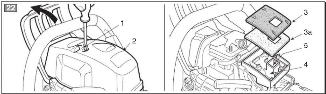
- Models 36 and 43
To clean the filter (Fig. 22):
- Move the front hand guard forward.
– Unscrew the screw (1) and remove the cover (2).
- Remove the sponge pre-filter (3a) and filter element (3).
- Slightly hit the filtering element (3) to remove dirt.
- If necessary, clean the sponge pre-filter (3a) and filtering element (3) with hot soapy water or detergent or clean with a jet of compressed air.
- Eliminate all sawdust and dirt residue in the filter housing (4) being careful it does not penetrate in the suction duct (5).
- Reassemble the filtering element (3) and sponge pre-filter (3a) only when thoroughly dry.
- Remount the cover (2).
- Models 46 and 52
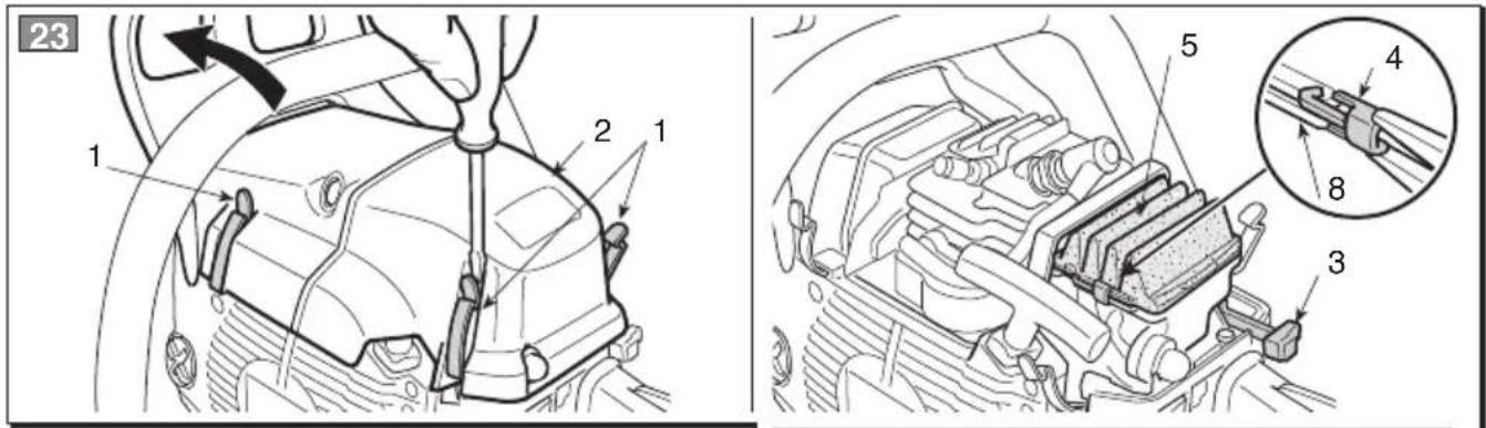
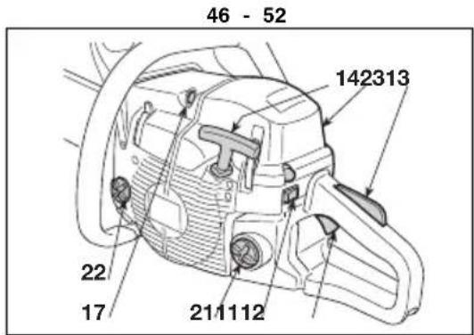
To clean the filter (Fig. 23):
- Move the front hand guard forward.
- Using a screwdriver, remove the three side springs (1) and the cover (2).
- Extract the starter knob (3) and, using pliers, extract the two side stops (4).
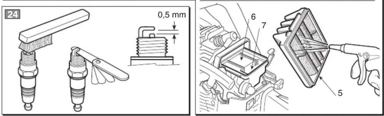
- Remove the filter element (5) and tap it gently to remove any dirt and, if necessary, clean it with hot soapy water or detergent. If you are using compressed air, aim the jet so that it blows from the inside towards the outside.
- Eliminate all sawdust and dirt residue in the filter
housing (6) being careful it does not penetrate in the suction duct (7).
- Reassemble the filter element (5) only when thoroughly dry, being careful to perfectly line up the two side protrusions (8) with the filter housing protrusions.
– Reassemble the two side stops (4).
- Reassemble the cover (2) and hook the three springs (1).
CHECKING THE SPARK PLUG (Fig. 24)
The spark plug can be accessed by removing the air filter cover.
Periodically remove and clean the spark plug using a metal brush to get rid of any deposits.
Check and reset the correct distance between the electrodes.
Replace the spark plug and fasten it firmly using the supplied wrench.
The spark plug must be replaced with one with the same characteristics whenever the electrodes have burnt or the insulation has worn, and in any case every 100 working hours.
TUNING THE CARBURETTOR
The carburettor is tuned by the manufacturer to achieve maximum performance in all situations, with a minimum emission of toxic gas in compliance with the regulations in force.
When performance is poor, first check that the chain runs smoothly and the bar rails are not distorted, then contact your dealer to check the carburetion and the engine.
• Tuning minimum speed

WARNING!
The chain must not move when the engine is running idle. If the chain moves when the engine is running idle, contact your dealer to correctly regulate the engine.
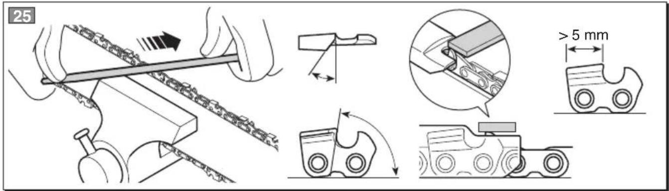
SHARPENING THE CHAIN

WARNING!
To ensure that the chainsaw works safely and efficiently, it is essential that the cutting components are well-sharpened.
Sharpening is necessary when:
• The sawdust looks like dust.
• Cutting becomes more difficult.
- The cut is not straight.
• Vibrations increase.
- Fuel consumption increases.

WARNING!
If the chain is not suffi-
the kick-back's risk in-
A specialized centre will sharpen the chain using the right tools to ensure minimum removal of material and even sharpness on all the cutting edges.
If you sharpen the chain yourself, use special round-section files with the right diameter depending on the type of chain (see “Chain Maintenance Table”). You need a certain amount of skill and experience to avoid damaging the cutting edges.
Sharpen the chain as follows (Fig. 25):
- Switch off the engine, release the chain brake and secure the bar with the chain in a vice so that the chain can run smoothly.
– Tighten the chain if it is loose.
- Mount the file in the guide and then insert it in the tooth at a constant angle from the cutting edge.
- Sharpen in a forward motion a few times and repeat this on all the cutting edges facing the same way (right or left).
- Turn the bar over in the vice and repeat on all the other cutting edges.
- Check that the limiter tooth does not stick out further than the inspection instrument and file any projecting parts with a flat file, rounding off the edge.
– After sharpening, remove all traces of filing and dust and lubricate the chain in an oil bath.
Replace the chain whenever:
- The length of the cutting edges reduces to 5 mm or less;
– There is too much play between the links and the rivets.
Chain maintenance table

WARNING!
The specifications of the chain and the bar homologated for this machine
are shown in the "EC Conformity Statement" provided. Do not use other types of chains or bars for safety reasons.
The table gives the sharpening data for different types of chains, but this does not mean you can use different chains from the homologated one.
| Chain pitch Limiter | tooth level (a) File diameter (d)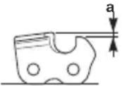 | 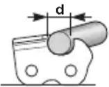 |
| inches mm | inches mm inches mm | | | | |
| 3/8 Mini | 9.32 0.018 0.45 | 5/32 | 4.0 | | |
| 0.325 | 8.25 0.026 0.65 | 3/16 | 4.8 | | |
| 3/8 | 9.32 0.026 | 0.65 13/64 | 5.2 | | |
| 0.404 | 10.26 | 0.031 | 0.80 | 7/32 | 5.6 |
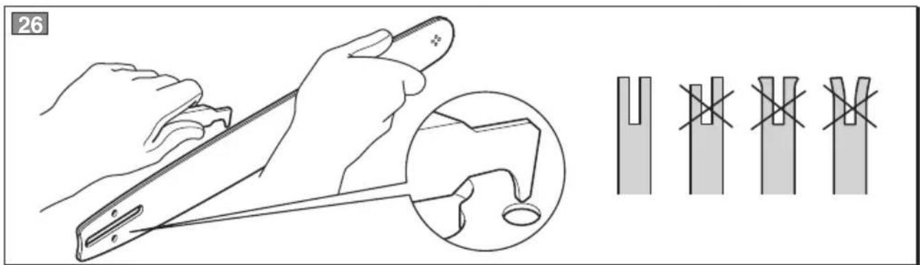
BAR MAINTENANCE (Fig. 26)
To avoid asymmetrical wear on the bar, make sure it is turned over periodically.
To keep the bar in perfect working order, proceed as follows:
– grease the bearings on the nose sprocket (if present) with the syringe;
- Clean the bar groove with the scraper (not included);
– clean the lubrication holes;
– with a flat file, remove burr from the edges and level off the guides.
Replace the bar whenever:
– the groove is not as deep as the height of the drive links (which must never touch the bottom);
– the inside of the guide is worn enough to make the chain lean to one side.
All maintenance operations not foreseen in this manual must be performed exclusively by your dealer.
All and any operations performed in unauthorised centres or by unqualified persons will totally invalidate the warranty.
STORAGE
After every work stint, clean the machine thoroughly to remove all dust and debris, and repair or replace any faulty parts.
The machine must be stored in a dry place away from the elements and with the bar cover correctly fitted.
LONG PERIODS OF DISUSE
IMPORTANT
If you are not going to use
the machine for a period of more than 2-3 months, we recommend you do a few things before putting it away. This will make it easier when you want to use the machine again and will also prevent permanent damage to the engine.
- Storage
Before putting the machine away:
- Unscrew the two nuts, remove the guard and remove the chain and rod.
- Empty the oil tank, fill with about 100-120 cc of specific liquid detergent and plug the cap.
- Fit the guard back on without tightening the nuts.
- Start the engine and keep it running until all detergent is used.
- Start the engine and run it idle until it uses up all
the fuel that is left in the tank and the carburet-tor.
- Remove the spark plug after the engine cools.
- Pour a teaspoon of (new) 2-stroke engine oil into the spark plug slot.
- Pull the starter grip several times to deliver oil to the cylinder.
- Replace the spark plug with the piston in the dead end upper position (visible from the spark plug slot when the piston is at maximum stroke).
- Restarting work
When you wish to start using the machine again:
- Remove the spark plug.
– Pull the starter rope a few times to eliminate excess oil.
- Check the spark plug as described in chapter "Checking the spark plug".
– Prepare the machine as indicated in the paragraph entitled “Preparing for work”.
9. TROUBLESHOOTING
PROBLEM LIKELY CAUSE SOLUTION
| 1) The engine will not start or will not keep running | - Incorrect starting procedure | - Follow the instructions (see chapter 6) |
| - Dirty spark plug or incorrect distance between the electrodes | - Check the spark plug (see chapter 8) |
| - Air filter clogged | - Clean and/or replace the filter (see chapter 8) |
| - Carburetion problems | - Contact your dealer |
| 2) The engine starts but is lacking in power | - Air filter clogged | - Clean and/or replace the filter (see chapter 8) |
| - Carburetion problems | - Contact your dealer |
| 3) The engine runs irregularly and lacks in power when revved | - Dirty spark plug or incorrect distance between the electrodes | - Check the spark plug (see chapter 8) |
| - Carburetion problems | - Contact your dealer |
| 4) The engine gives off an excessive amount of smoke | - Incorrect composition of the fuel mixture | - Prepare the fuel mixture according to the instructions (see chap. 5) |
| - Carburetion problems | - Contact your dealer |
| 5) No oil is released | - Bad quality oil | - Empty the tank, clean it and pipes with liquid detergent and change the oil. |
| - Lubrication holes are clogged | - Clean |
10. ACCESSORIES
The table contains a list of all possible combinations between bar and chain, indicating those which may be used on each machine, marked with the symbol “*

WARNING!
In consideration that the selection, application and usage of bar and
chain are actions made solely by the user, the latter assumes responsibility for damages of any kind due to such actions. When in doubt or if lacking knowledge of the specificity of each bar or chain, contact your retailer or specialised gardening centre.
Bar and chain combinations
| Pitch BAR CHAIN Model | | |
| Inches | LengthInches / cm | Groove widthInches / mm | Code Code | | 36 43 45 52 | | |
| 3/8" | 14" / 35 cm | 0,050"/1,3mm | 118800623/0 | 4113703 | * | | | |
| 325" | 15" / 38 cm | 0,058"/1,5mm | 118800624/0 | 4113724 | | * | * | |
| 325" | 18" / 45 cm | 0,058"/1,5mm | 118800625/0 | 4113722 | | | * | * |
Cher Client,
COMMANDES ET RAVITAILLEMENT
natural_image
Icon of a person reading a book inside a circle (no text or symbols)

natural_image
Black and white icon of a person wearing a helmet and sunglasses, enclosed in a circle (no text or symbols)
natural_image
Icon of a person reading a book inside a circle (no text or symbols)

natural_image
Black and white icon of a person wearing a helmet and sunglasses, enclosed in a circle (no text or symbols)
natural_image
Icon of a person reading a book inside a circle (no text or symbols)

natural_image
Black and white icon of a person wearing a helmet and sunglasses, enclosed in a circle (no text or symbols)
natural_image
Icon of a person reading a book inside a circle (no text or symbols)

natural_image
Black and white icon of a person wearing a helmet and sunglasses inside a circle (no text or symbols)
natural_image
Icon of a person reading a book inside a circle (no text or symbols)

natural_image
Black and white icon of a person wearing a helmet and sunglasses, enclosed in a circle (no text or symbols)
PROBLEMA CAUSA PROVÁVEL SOLUÇÃO
1. TAYTOTHTA TΩN KYPIOTEΡΩΝ ΕΞAPTHMATΩΝ
ΒΑΣΙΚΑ ΕΞΑΡΤΗΜΑΤΑ
natural_image
Icon of a person reading a book inside a circle (no text or symbols)

natural_image
Black and white icon of a person wearing a helmet and sunglasses, enclosed in a circle (no text or symbols)
KUMANDALAR VE İKMALLER
natural_image
Icon of a person reading a book inside a circle (no text or symbols)

natural_image
Black and white icon of a person wearing a helmet and sunglasses, enclosed in a circle (no text or symbols)
MOTOR STOPU (Res. 10)
STEROWANIE I NAPEŁNIANIE
natural_image
Icon of a person reading a book inside a circle (no text or symbols)

natural_image
Black and white icon of a person wearing a helmet and sunglasses, enclosed in a circle (no text or symbols)
UPRAVLJANJE IN POLNJENJE GORIVA
| Maksimalne vrednosti hrupa in vibracij [1] | Model | 36 43 | 46 52 | | |
| Nivo akustičnega pritiska na ušesa operate(ISO 22868) | dB(A) 98,9 | 98,9 | 102,3 | 101,6 | |
| - Nezanesljivost meritve (2006/42/CE - EN 27574) | dB(A) | 2,5 | 2,5 | 2,5 | 2,5 |
| Nivo akustične moči izmerje(ISO 22868) | dB(A) | 108,1 | 108,1 | 113 | 113,4 |
| - Nezanesljivost meritve (2006/42/CE - EN 27574) | dB(A) | 2,5 | 2,5 | 2,5 | 2,5 |
| Nivo vibracij ISO 22867) | m/sec ^2 | 7,5 - 6,2 | 7,5 - 6,2 | 4,9 - 3,6 | 5,7 - 4,9 |
| - Nezanesljivost meritve (2006/42/CE - EN 12096) | m/sec | 0,5 | 0,5 | 0,5 | 0,5 |
| TEHNIČNI PODATKI |
| Motor (enocilindrski dvotaktni 2 stopnji) - prostornina | cm ^3 | 36,3 | 40,2 | 45 | 52 |
| Mešanica (bencin / olje) | % | 50:1 = 2 % | 50:1 = 2 % | 50:1 = 2 % | 50:1 = 2 % |
| Moč | kW | 1,5 | 2,0 | 2,2 | 2,4 |
| Število obratov na minimumu | 1min | 2800 ± 150 | 2800 ± 150 | 2800 ± 150 | 2800 ± 150 |
| Maksimalno dovoljeno število obratov brez obremenitve z montirano verigo 1min | | 11300 | 12000 | 12500 | 12500 |
| Prostornina rezervoarja za gorivo | cm ^3 | 370 | 370 | 500 | 500 |
| Specifična poraba pri največji moči | g/kWh | 490 | 410 | 510 | 500 |
| Prostornina oljnega rezervoarja | cm ^3 | 190 | 190 | 300 | 300 |
| Zobje pastorka verige | | 6 | 7 | 7 | 7 |
| Teža (s praznim rezervoarjem) | kg | 4,2 | 4,1 | 4,7 | 4,7 |
natural_image
Icon of a person reading a book inside a circle (no text or symbols)

natural_image
Black and white icon of a person wearing a helmet and sunglasses, enclosed in a circle (no text or symbols)
UPORABA MOTORJA (Slika 10)
POMEMBNO
DALJŠE OBDOBJE NEUPORABE
natural_image
Silhouette of a person reading a book inside a circle (no text or symbols)

natural_image
Black and white icon of a person wearing a helmet and sunglasses, enclosed in a circle (no text or symbols)
UPRAVLJAČKI ELEMENTI I NADOLIJEVANJE
- Prekidač za zaustavljanje motora
- Ručica gasa
- Osigurač gasa
- Ručica za paljenje
- Gumb čoka (Starter)
- Gumb uređaja za ubrizgavanje (Primer)
-
Ventil za dekompresiju (samo za mod. 46/52)
-
Poklopaca spremnika za mješavinu
- Poklopac spremnika ulja za lanac
- Poklopac filtera za zrak


PLOČICA S PODACIMA
10.1) Oznaka sukladnosti u skladu s direktivom 2006/42/EZ
10.2) Naziv i adresa proizvođača
10.3) Razina zvučne snage LWA u skladu s direktivom 2000/14/EZ
10.4) Proizvođačeva oznaka modela
10.5) Model stroja
10.6) Serijski broj
10.7) Godina proizvodnje
10.8) Šifra Artikla
10.9) Broj emisija

| Maksimalne vrijednosti buke i vibracija [1] | Model | 36 43 | 46 52 | | |
| Razina zvučnog tlaka na ušima rukovatel (ISO 22868) | dB(A) 98,9 98,9 102,3 101,6 | | |
| – Mjerna nesigurnost (2006/42/EZ - EN 27574) | dB(A) | 2,5 | 2,5 | 2,5 | 2,5 |
| Izmjerena razina zvučne snag (ISO 22868) | dB(A) | 108,1 108,1 | 113 | 113,4 | |
| – Mjerna nesigurnost (2006/42/EZ - EN 27574) | dB(A) | 2,5 | 2,5 | 2,5 | 2,5 |
| Razina vibracija ISO 22867) | m/sec ^2 | 7,5 - 6,2 | 7,5 - 6,2 | 4,9 - 3,6 5 | 7 - 4,9 |
| – Mjerna nesigurnost (2006/42/EZ - EN 12096) | m/sec | 0,5 | 0,5 | 0,5 | 0,5 |
| TEHNIČKI PODACI |
| Motor (jednocilindrični, 2-taktni) – radni obujam | cm ^3 | 36,3 40 | 2 45 | 52 | |
| Mješavina (benzin-ulje) | % | 50:1 = 2 % | 50:1 = 2 % | 50:1 = 2 % | 50:1 = 2 % |
| Snaga | kW | 1,5 | 2,0 | 2,2 | 2,4 |
| Broj okretaja na minimumu | 1/min | 2800 ± 150 | 2800 ± 150 | 2800 ± 150 | 2800 ± 150 |
| Najveći dopušteni broj okretaja bez opterećenja, s montiranim lancet | min | 11300 | 12000 | 12500 | 12500 |
| Zapremina spremnika goriva | cm ^3 | 370 | 370 | 500 | 500 |
| Specifična potrošnja pri maksimalnoj snazi | g/kWh | 490 | 410 | 510 | 500 |
| Zapremina spremnika ulja | cm ^3 | 190 | 190 | 300 | 300 |
| Zupci lančanika | | 6 | 7 | 7 | 7 |
| Težina (s praznim spremnikom) | kg | 4,2 | 4,1 | 4,7 | 4,7 |
natural_image
Silhouette of a person reading a book inside a circle (no text or symbols)

natural_image
Black and white icon of a person wearing a helmet and sunglasses, enclosed in a circle (no text or symbols)
SIMBOLI NA STROJU (ako su prisutni)
UPORABA MOTORA (SI. 10)
VAŽNO
INNEHÅLLSFÖRTECKNING
KOMMANDON OCH PÄFYLLNING
natural_image
Icon of a person reading a book inside a circle (no text or symbols)

natural_image
Black and white icon of a monkey wearing a helmet and sunglasses, enclosed in a circle (no text or symbols)
VIVUT JA TÄYTÖT
natural_image
Icon of a person reading a book inside a circle (no text or symbols)

natural_image
Black and white icon of a person wearing a helmet and sunglasses, enclosed in a circle (no text or symbols)
1. POLTTOAINESEOKSEN VALMISTUS
BETJENINGER OG PÄFYLDNINGER
natural_image
Icon of a person reading a book inside a circle (no text or symbols)

natural_image
Black and white icon of a person wearing a helmet and sunglasses, enclosed in a circle (no text or symbols)
KONTROLLER OG ETTERFYLLING
- Bryter for stans av motoren
- Gasskontroll
- Blokkering av gassen
- Startsnor
- Choke-kontroll (Starter)
- Pumpekommando (Primer)
-
Dekompresjonsventil (kun for modellene 46/52)
-
Lokk til drivstofftanken
- Lokk til kjedeoljetanken
- Lokk til luftfilter
TYPEPLAATJE
| TEKNISKE DATA [1] | Model | 36 43 | 46 52 | | |
| Maksimale verdier for støy og vibrasjoner (ISO 22868) | dB(A) | 98,9 | 98,9 | 102,3 | 101,6 |
| - Måleusikkerhet (2006/42/EG - EN 27574) | dB(A) | 2,5 | 2,5 | 2,5 | 2,5 |
| Lydtrykknivå på operatørens øre (ISO 22868) | dB(A) | 108,1 | 108,1 | 113 | 113,4 |
| - Måleusikkerhet (2006/42/EG - EN 27574) | dB(A) | 2,5 | 2,5 | 2,5 | 2,5 |
| Vibrasjonsnivå (ISO 22867) | m/sec ^2 | 7,5 - 6,2 | 7,5 - 6,2 | 4,9 - 3,6 | 5,7 - 4,9 |
| - Måleusikkerhet (2006/42/EG - EN 12096) | m/sec ^2 | 0,5 | 0,5 | 0,5 | 0,5 |
| TEKNISKE DATA |
| Motor (ensylindret, totakts) – slagvolum | cm ^3 | 36,3 | 40,2 | 45 | 52 |
| Blanding (bensin/olje)) | % | 50:1 = 2 % | 50:1 = 2 % | 50:1 = 2 % | 50:1 = 2 % |
| Effekt | kW | 1,5 | 2,0 | 2,2 | 2,4 |
| Turtall ved tomgang | 1min | 2800 ± 150 | 2800 ± 150 | 2800 ± 150 | 2800 ± 150 |
| Maks tillatt turtall uten belastning med montert kjede | 1min | 11300 | 12000 | 12500 | 12500 |
| Drivstofftankens kapasitet | cm ^3 | 370 | 370 | 500 | 500 |
| Forbruk ved maks effekt | g/kWh | 490 | 410 | 510 | 500 |
| Oljetankens kapasitet | cm ^3 | 190 | 190 | 300 | 300 |
| Kjededrevets tenner | | 6 | 7 | 7 | 7 |
| Vekt (med tom tank) | kg | 4,2 | 4,1 | 4,7 | 4,7 |
natural_image
Icon of a person reading a book inside a circle (no text or symbols)

natural_image
Black and white icon of a person wearing a helmet and sunglasses, enclosed in a circle (no text or symbols)
D) VEDLIKEHOLD OG LAGRING
5. KONTROLL MED KJEDETS SPENNING

ADVARSEL!
lokket, og skru
3d#ED ARBEIDETS SLUTT gre-
Ved arbeidets slutt:
8. VEDLIKEHOLD OG LAGRING

ADVARSEL!
OVLÁDACÍ PRVKY A DOPLŇOVÁNÍ
natural_image
Icon of a person reading a book inside a circle (no text or symbols)

natural_image
Black and white icon of a person wearing a helmet and sunglasses, enclosed in a circle (no text or symbols)
1. KONTROLY, KTERÉ JE TŘEBA PROVÁDĚT BĚHEM PRACOVNÍ ČINNOSTI
JEDNOTKA SPOJKY (Obr. 20)
OBDOBÍ DLOUHODOBÉ NEČINNOSTI
DŮLEŽITÉ
natural_image
Icon of a person reading a book inside a circle (no text or symbols)

natural_image
Black and white icon of a person wearing a helmet and sunglasses, enclosed in a circle (no text or symbols)
MAGYARÁZÓ JELZÉSEK A GÉPEN (ha vannak)
| Максимални вредности за бучава и вибрации [1] | Модел | 36 43 | 46 52 | | |
| Нивото на акустичен притисок врз ушите на операторот (ISO 22868) | dB(A) 98,9 | 98,9 102,3 | 101,6 | | |
| – Несигурност за мерење (2006/42/EY - EN 27574) | dB(A) | 2,5 | 2,5 | 2,5 | 2,5 |
| Ниво на измерена акустична моќност (ISO 22868) | dB(A) | 108,1 | 108,1 | 113 | 113,4 |
| – Несигурност за мерење (2006/42/EY - EN 27574) | dB(A) | 2,5 | 2,5 | 2,5 | 2,5 |
| Ниво на вибрации (ISO 22867) | m/sec ^2 | 7,5 - 6,2 | 7,5 - 6,2 | 4,9 - 3,6 | 5,7 - 4,9 |
| – Несигурност за мерење (2006/42/EY - EN 12096) | m/sec ^2 | 0,5 | 0,5 | 0,5 | 0,5 |
| ТЕХНИЧКИ ПОДАТОЦИ |
| Мотор (моноцилиндричен двотактен) – зафатнина | цм ^3 | 36,3 40,2 | 45 | 52 | |
| Мешавина (бензин/масло) | % | 50:1 = 2 % | 50:1 = 2 % | 50:1 = 2 % | 50:1 = 2 % |
| Моќност | kW | 1,5 | 2,0 | 2,2 | 2,4 |
| Број на вртежи на минимум | ^1 /мин | 2800 ± 150 | 2800 ± 150 | 2800 ± 150 | 2800 ± 150 |
| Број на дозволени вртежи на максимум без оптоварување со поставен ланец | ^1 /мин | 11300 | 12000 | 12500 | 12500 |
| Капацитет на резервоарот за гориво | цм ^3 | 370 | 370 | 500 | 500 |
| Специфична потрошувачка на максимальна моќност | g/kWh | 490 | 410 | 510 | 500 |
| Капацитет на резервоарот за масло | цм ^3 | 190 | 190 | 300 | 300 |
| Запци на ланецот | | 6 | 7 | 7 | 7 |
| Тежина (со празен резервоар) | кг | 4,2 | 4,1 | 4,7 | 4,7 |
natural_image
Silhouette of a person reading a book inside a circle (no text or symbols)

natural_image
Black and white icon of a person wearing a helmet and sunglasses, enclosed in a circle (no text or symbols)
KOMANDOS IR PRIPILDYMAI
natural_image
Icon of a person reading a book inside a circle (no text or symbols)

natural_image
Black and white icon of a person wearing a helmet and sunglasses, enclosed in a circle (no text or symbols)
AIŠKINAMIEJI SIMBOLIAI ANT JRENGINIO (jeigu yra)

5. PASIRUOŠIMAS DARBUI
1. MIŠINIO PARUOŠIMAS
SUTEPIMO ANGA (Pav. 21)
VADĪBAS IERĪCES UN UZPILDE
natural_image
Icon of a person reading a book inside a circle (no text or symbols)

natural_image
Black and white icon of a person wearing a helmet and sunglasses inside a circle (no text or symbols)
PASKAIDROJOŠI SIMBOLI UZ MAŠINAS (ja ir)

COMENZI ŞI DOTĂR
natural_image
Silhouette of a person reading a book inside a circle (no text or symbols)

natural_image
Black and white icon of a person wearing a helmet and sunglasses, enclosed in a circle (no text or symbols)
КОМАНДИ И ЗАРЕЖДАНЕ
| Максимални стойности на шум и вибрации [1] | Модел | 36 | 43 | 46 | 52 |
| Ниво на акустично налягане в ухото на оператора (ISO 22868) | dB(A) | 98,9 | 98,9 | 102,3 | 101,6 |
| – Несигурност на измерване (2006/42/CE - EN 27574) | dB(A) | 2,5 | 2,5 | 2,5 | 2,5 |
| Измерено ниво на акустична мощност (ISO 22868) | dB(A) | 108,1 | 108,1 | 113 | 113,4 |
| – Несигурност на измерване (2006/42/CE - EN 27574) | dB(A) | 2,5 | 2,5 | 2,5 | 2,5 |
| Ниво на вибрация (ISO 22867) | m/sec ^2 | 7,5 - 6,2 | 7,5 - 6,2 | 4,9 - 3,6 | 5,7 - 4,9 |
| – Несигурност на измерване (2006/42/CE - EN 12096) | m/sec ^2 | 0,5 | 0,5 | 0,5 | 0,5 |
| ТЕХНИЧЕСКИ ДАННИ |
| Двигател (едноцилиндров двутактов) – обем на цилиндъра | cm ^3 | 36,3 | 40,2 | 45 | 52 |
| Смес (бензин / масло) | % | 50:1 = 2 % | 50:1 = 2 % | 50:1 = 2 % | 50:1 = 2 % |
| Мощност | kW | 1,5 | 2,0 | 2,2 | 2,4 |
| Брой обороти минимум | 1/мин | 2800 ± 150 | 2800 ± 150 | 2800 ± 150 | 2800 ± 150 |
| Брой максимально допустими обороти без натоварване при монтирана верига | 1/мин | 11300 | 12000 | 12500 | 12500 |
| Вместимост на горивния резервоар | cm ^3 | 370 | 370 | 500 | 500 |
| Специфичен разход при максимальна мощност | гр/кВч | 490 | 410 | 510 | 500 |
| Вместимост на масления резервоар | cm ^3 | 190 | 190 | 300 | 300 |
| Зъбци на пиньона на предавателна верига | | 6 | 7 | 7 | 7 |
| Тегло (с празен резервоар) | кг | 4,2 | 4,1 | 4,7 | 4,7 |
natural_image
Icon of a person reading a book inside a circle (no text or symbols)

natural_image
Black and white icon of a person wearing a helmet and sunglasses inside a circle (no text or symbols)
JUHTIMISSEADMED JA TANKIMINE
- Mootori seiskamise lüliti
- Gaasihoob
- Gaasihoova pidur
- Käivitamisnupp
- Rikastusseade (Starter)
- Külmstardi membraanpump (Primer)
-
Dekompressor (ainult mudelile 46/52)
-
Segumahuti kork
- Ketiõli mahuti kork
- Ōhufiltri kaas

MATRIKLIETIKETT
10.1) Vastavusmärgistus vastavalt direktiivile 2006/42/CE
10.2) Ehitaja nimi ja aadress
10.3) Müra tase LWA vastavalt direktiivile 2000/14/CE
10.4) Ehitaja viitemudel
10.5) Masina mudel
10.6) Matriklinumber
10.7) Valmistusaasta
10.8) Artiklikood
10.9) Emissioni number
natural_image
Icon of a person reading a book inside a circle (no text or symbols)

natural_image
Black and white icon of a person wearing a helmet and sunglasses, enclosed in a circle (no text or symbols)
PILTSÜMBOLID MASINAL (kui on olemas)

SAELATI HOOLDUS (Joon. 26)