DWC 184500 Li - Screwdriver FESTOOL - Free user manual and instructions
Find the device manual for free DWC 184500 Li FESTOOL in PDF.

| Product type | Cordless drywall screwdriver |
| Brand | Festool |
| Model | DWC 184500 Li |
| Motor voltage | 18 V |
| No-load speed (model 2500) | 0 – 2500 rpm |
| No-load speed (model 4500) | 0 – 4500 rpm |
| Screwing torque (soft/hard) – model 2500 | 7 / 18 Nm |
| Screwing torque (soft/hard) – model 4500 | 5 / 14 Nm |
| Bit holder in spindle | 1/4" DIN 3126 / ISO 1173 |
| Weight (without battery pack) | 1.1 kg |
| Weight with depth stop (without battery) | 1.2 kg |
| Weight with magazine (without battery) | 1.5 kg |
| Power supply | Li-Ion battery 18 V (type BP, BPS, BPC) |
| Charger | TCL 3 (for Festool NiMH, NiCd, Li-Ion batteries) |
| Main functions | Automatic screwing, depth adjustment (±0.1 mm), reversible rotation direction, AUTO/MAN mode, depth stop, adjustable screw magazine |
| Maintenance and cleaning | Cleaning with compressed air, lubrication of the guide bush, replacement of worn parts |
| Safety | Automatic stop at the end of screwing, overload and overheating protection, warning acoustic signals |
| Spare parts and repairability | Use only original Festool parts; repairs only by authorized service center |
| General information | CE compliant, CE marking 2013, sound pressure level 78 dB(A), sound power level 89 dB(A), hand-arm vibration < 3.5 m/s² |
Frequently Asked Questions - DWC 184500 Li FESTOOL
User questions about DWC 184500 Li FESTOOL
0 question about this device. Answer the ones you know or ask your own.
Ask a new question about this device
Download the instructions for your Screwdriver in PDF format for free! Find your manual DWC 184500 Li - FESTOOL and take your electronic device back in hand. On this page are published all the documents necessary for the use of your device. DWC 184500 Li by FESTOOL.
USER MANUAL DWC 184500 Li FESTOOL
natural_image
Two black electric spray machines with attached base plates, no visible text or symbols on the main body.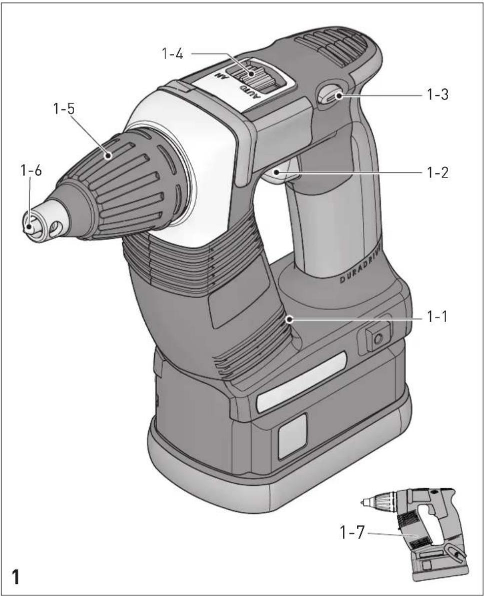
natural_image
Technical line drawing of a mechanical component with directional arrows indicating rotation or movement (no text or symbols)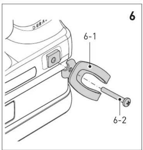
natural_image
Line drawing of a mechanical device with no visible text or symbolsTCL 3
 | [BPC 12, BPC 15, BPC 18]BPS 12, BPS 15, BPS 18BP 12, BP 15, BP 18 | ||
 | V~ | 220 - 240 | |
| Hz | 50/60 | ||
 | V= | 10,8 - 18 | |
 | A | 3 | |
| [±687] | °C | -5 - 45 | |
| [WK02] | II | ||
 | ||
| Lilon 4,2 Ah | min. | ~70 |
| Lilon 5,2 Ah | min. | ~90 |
| BPC 18 Li | ||
 | T18+3, PDC 18, DRC 18, DWC 18,BHC 18, TSC 55, PSC 420,PSBC 420, KAL II | |
 | V= | 18 |
 | Ah | 5,2 |
| [SADC] | kg | 0,68 |
DWC 18-2500 a_h = 2.8 m/s^2
$$ K = 1, 5 \mathrm{m} / \mathrm{s} ^ {2} $$
DWC 18-4500 a_h=3,5 m/s^2
$$ K = 1, 5 \mathrm{m} / \mathrm{s} ^ {2} $$
Original operating manual
1 Symbols
Symbol Significance

Warning of general danger

Risk of electric shock

Read operating instructions and safety notices!

Wear ear protection.

Wear protective gloves.

Wear a dust mask.

Wear protective goggles.

Do not dispose of with domestic waste.

Tip or advice

Handling instruction
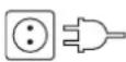
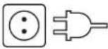
Mains voltage (input) and frequency

Voltage (output)

Rapid charging max.

Permitted temperature range

Safety class II

Charging times

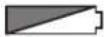
Capacity

Weight
2 Safety instructions
2.1 General safety instructions

WARNING! Read all safety warnings and all instructions. Failure to follow the warnings and instructions may result in electric shock, fire and/or serious injury.
Save all warnings and instructions for future reference.
The term "power tool" in the warnings refers to your mains-operated (corded) power tool or battery-operated (cordless) power tool.
2.2 Machine-related safety instructions
- Hold power tool by insulated gripping surface, when performing an operation where the fastener may contact hidden wiring Fasteners con-
tacting a "live" wire may make exposed metal parts of the power tool "live" and could give the operator an electric shock.
- Use suitable detectors to determine if utility lines are hidden in the work area or call the local utility company for assistance. Contact with electric lines can lead to fire and electric shock. Damaging a gas line can lead to explosion. Penetrating a water line causes property damage or may cause an electric shock.

natural_image
Four black circular icons representing different workplace safety symbols: helmet, glasses, head, and hand (no text or labels)- Wear suitable protection: such as ear protection, safety goggles, a dust mask for work which generates dust, and protective gloves when working with raw materials and when changing tools.

CAUTION! Power tool can block and cause sudden kickback! Switch off immediately!
- Hold the power tool firmly in your hand. Adjust the torque correctly for screwing. Be prepared for a high reaction torque, which may cause the power tool to turn and possibly lead to injury.
- Do not use the power tool in the rain or in damp surroundings. Moisture in the power tool may cause a short circuit and burning.
- Do not lock the on/off switch permanently!
- Connecting the magazine attachment and dry-wall screwdriver results in a device, which is subject to the safety regulations and instruction for the drywall screwdriver.
2.3 Battery pack and charger safety instructions
- This charger can be operated by persons with reduced physical, sensory or mental capabilities or a lack of practical experience and knowledge, provided they are supervised or have been instructed to use the machine safely and understand the dangers of machine operation. Children are not allowed use or play with the machine.
- Do not open the battery pack or the charger!
- Prevent metal parts (e.g. metal chips) or fluids from entering the charger!
-
Do not use power adapters or battery packs form other manufacturers to operate the cordless power tool. Do not use any charger from other manufacturers for charging the battery pack. The use of impermissible accessories may result in electric shock and / or serious accidents!
-
Protect the battery pack from excessive heat > 50 °C or constant heat sources such as sunlight or naked flames!
- Never use water to extinguish burning li-ion battery packs! Use sand or a fire blanket.
- Check the plug and the cable regularly and should either become damaged, in order to avoid a hazard, have them replaced by an authorised after-sales service workshop.
- Always pull the mains plug out of the socket when the charger is not in use.
- Only for AS/NZS: The tool shall always be supplied via residual current device with a rated residual current of 30 mA or less.
2.4 Emission levels
Levels determined in accordance with EN 60745 are typically:
Sound pressure level
$$ L _ {P A} = 7 8 \mathrm{dB(A)} $$
Sound power level
$$ L _ {W A} = 8 9 \mathrm{dB(A)} $$
Uncertainty
$$ K = 3 \mathrm{dB} $$

Wear ear protection.
Vibration emission value a_h (vector sum for three directions) and uncertainty K measured in accordance with EN 60745:
DWC 18-2500
$$ a _ {h} = 2, 8 m / s ^ {2} $$
$$ K = 1, 5 \mathrm{m} / \mathrm{s} ^ {2} $$
DWC 18-4500
$$ a _ {h} = 3, 5 \mathrm{m} / \mathrm{s} ^ {2} $$
$$ K = 1, 5 \mathrm{m} / \mathrm{s} ^ {2} $$
The specified emissions values (vibration, noise) – are used to compare machines.
– They are also used for making preliminary esti-
4 Technical data
mates regarding vibration and noise loads during operation.
- They represent the primary applications of the power tool.
Increase possible for other applications, with other insertion tools or if not maintained adequately. Take note of idling and downtimes of machine!
3 Intended use
The drywall screwdriver is designed for the following works:
DWC 18-2500
- Gypsum fibreboards on metal and wooden constructions - Drywall screws with milling ribs
- Chip boards/OSB on wooden constructions bis D 5 mm - Wood construction and chip board screws up to dia. 5 mm
DWC 18-4500
- Gypsum plaster boards on metal profile rails ( ≤slant 0.88 mm) - Drywall screws with fine thread
- Gypsum plaster boards on metal profile rails ( ≤ 2.25 mm) - Drywall screws, self-drilling
- Gypsum plaster boards on wooden constructions
- Drywall screws with coarse thread
Charger TCL 3 suitable for
- charging Festool battery packs: BP, BPS and BPC (NiMH, NiCd, li-ion are recognised automatically.)
- indoor use only.

The user is liable for improper or non-intended use; this also includes continuous industrial operation.
| Cordless drywall screwdriver | DWC18-2500 | DWC18-4500 |
| Motor voltage | 18 V | 18 V |
| Idle speed* | 0 - 2500 min ^-1 | 0 - 4500 min ^-1 |
| Torque (hard / soft) | 7 / 18 Nm | 5 / 14 Nm |
| Chuck | 1/4 '' DIN 3126 / ISO 1173 | 1/4 '' DIN 3126 / ISO 1173 |
| Weight (without battery pack) | 1,1 kg | 1,1 kg |
| Weight with depth stop (without battery pack) | 1.2 kg | 1.2 kg |
| Weight with magazine attachment (without battery pack) | 1.5 kg | 1.5 kg |
* Speed specifications with fully charged battery pack.
i Further technical data on the charger and battery packs can be found on page 6.
5 Machine features
[1-1] Bit store
[1-2] On/Off switch
[1-3] Right/left switch
[1-4] AUTO/MAN switch
[1-5] Depth stop
[1-6] Bit
[1-7] Insulated gripping surfaces (grey shaded area)
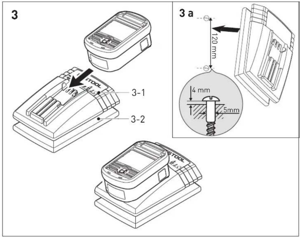
[3-1] LED-Display
[3-2] Cable holder
[3a] Wall mount for charger
Accessories shown or described are sometimes not included in the scope of delivery.
The specified illustrations appear at the beginning of the Operating Instructions.
6 Operation
6.1 Charger cable holder [3-2]
![FESTOOL DWC 184500 Li - Charger cable holder [3-2] - 1](/content/2026/02/396736/images/d6ba49ed7cb9ee5c453e1ef55da6dfffdcb88b9bba83b225e4dda7bb7f230813.jpg)
Unwind the cable completely from the recess before using the charger.
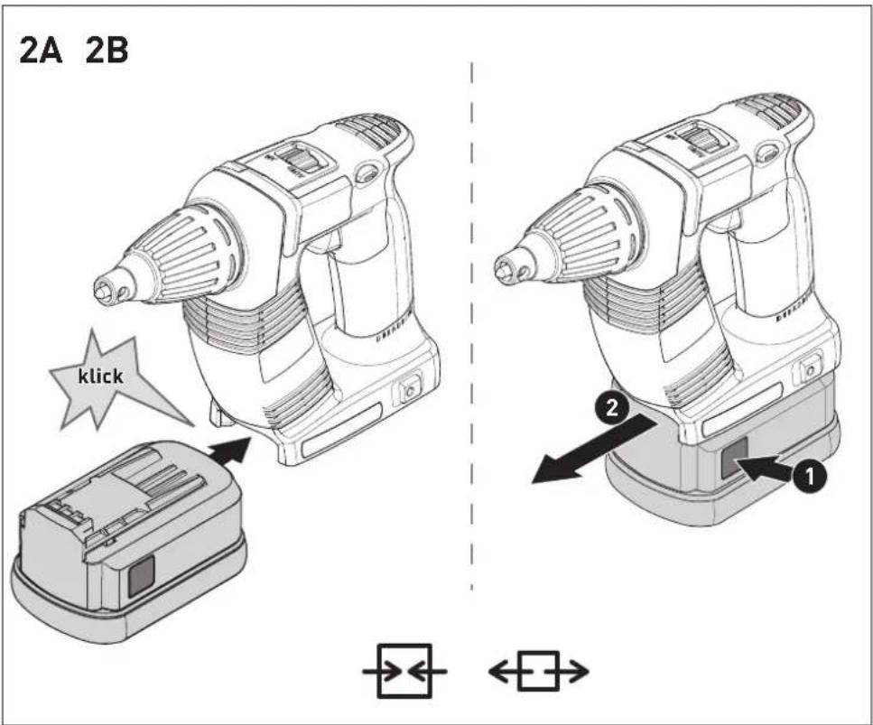
6.2 Changing the battery pack
Inserting the battery pack [2 A]
Removing the battery pack[2 B]
① Battery pack is ready for use immediately upon delivery and can be charged at any time.
6.3 Charging the battery pack [3]
The LED [3-1] on the charger indicates the respective operating status of the charger.
![FESTOOL DWC 184500 Li - Charging the battery pack [3] - 1](/content/2026/02/396736/images/f912fbbb82982686b9f0a1f7c131ace4713bf61e0e1a0733190661e9164d8254.jpg)
![FESTOOL DWC 184500 Li - Charging the battery pack [3] - 2](/content/2026/02/396736/images/5b418b58d31f7e482ae19f263eed9093b849eb070377213e61a925dbc63e7b70.jpg)
LED yellow - lit continuously
Charger is ready to use.

LED green - flashes quickly
Battery pack is charged to maximum capacity.


LED green - flashes slowly
Battery pack is charged with reduced current. Li-ion is charged to 80 %.


LED green - lit continuously
Charging is complete or is not restarted as current charge status is greater than 80%.


LED red - flashes
General fault indication, e.g. incomplete contact, short circuit, defective battery pack, etc.


LED red - lit continuously
Battery temperature is outside the permitted range.
7 Settings

CAUTION
Risk of injury
▶ Always switch off the power tool before adjusting settings!
7.1 Changing direction of rotation [1-3]
- Switch to the left = clockwise rotation
- Switch to the right = counterclockwise rotation
8 Tool holder, attachments

WARNING
Risk of injury
▶ Always disconnect the battery pack before performing any type of work on the machine!
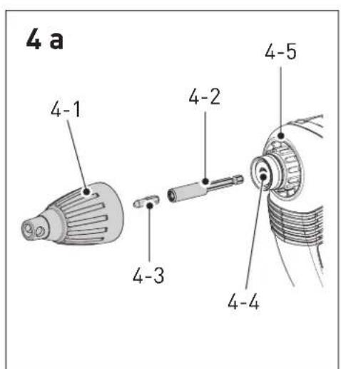
8.1 Bit holder
The bit holder is used for fast replacement of bits.


CAUTION
Hot and sharp tools
Risk of injury
▶ Do not use insert tools that are blunt or defective.
▶ Wear protective gloves.
Bit holder assembly
▶ Set the switch [1-4] into MAN position.
▶ Set the bit holder[4-2] completely to the hexagonal spindle opening[4-4].
▶ Attach bit into the holder[4-3].
▶ Then attach the depth stopper on the gear box as specified in chapter 9.2.
Bit holder disassembly
▶ Remove the depth stopper as specified in chapter 9.2.
▶ Use power to pull out the holder from the spindle opening.
8.2 Bit replacement
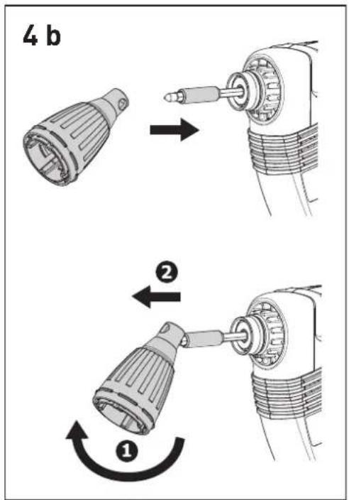
You can use the depth stopper [1-6] for the bit replacement [1-5] .
▶ Attach the depth stopper on the bit (see figure [4b]).
▶ By means of jamming the depth stopper with the bit and concurrent pulling, it is possible to pull out the bit.
▶ Then attach a new bit in the holder.
9 Working with the machine
9.1 On/Off switch [1-2]
① Pressing only the switch[1-2] does not start the machine – it is not a machine fault
① Upon screwing to the required depth, the power tool switches off!
The machine can be switched on by means of several methods:
a)
▶ Set the forward / reverse switch [1-3] into machine clockwise operation.
▶ Set the switch[1-4] into MAN position.
In order to switch on the power tool, apply the switch [1-2] and concurrently press the bit on the screw.
Use the switch [1-2] to gradually regulate the speed.
b)
▶ Set the forward / reverse switch [1-3] into machine clockwise operation.
▶ Set the switch [1-4] into AUTO position.
▶ Press the bit on the screw and the power tool will switch on.
Switch [1-2] does not need to be pressed. Maximum speed is set automatically.
b)
▶ Set the forward / reverse switch [1-3] into machine anti-clockwise operation.
▶ In order to start the power tool, press the switch [1-2].
The switch MAN/AUTO[1-4] is in any position.
Use the switch [1-2] to gradually regulate the speed.
① If the forward / reverse switch is set to anticlockwise operation, the screwdriver can be started only by pressing the switc[1-2] without additional pressure on the bit.
① It is not necessary to remove the depth stopper in order to unscrew screws.
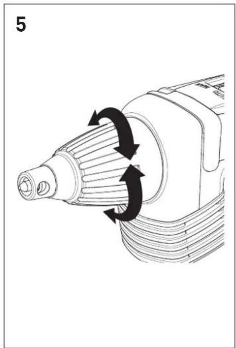
9.2 Depth stop
Turning the depth stopper [1-5] sets the screwing depth – see figure [5]. The setting accuracy is approx ± 0,1 mm.
Anti-clockwise screws are inserted deeper rotation
Clockwise rotation screws are inserted to lower depth
Upon setting the depth, set some screws to test and adjust the depth.
Depth stop assembly
▶ Fit the depth stop [4-1] on the gear box [4-5].
▶ Press until it engages in the groove.
Depth stop disassembly
▶ Remove the depth stop from the gear box by pulling it.
9.3 Scaffolding holder and belt clip
Use the belt clip[6-1] to temporarily attach the screwdriver on the working clothing – it can be attached by means of a screw[6-2] to the left or right of the power tool, and it is suitable for right and left handed people – see figure[6].
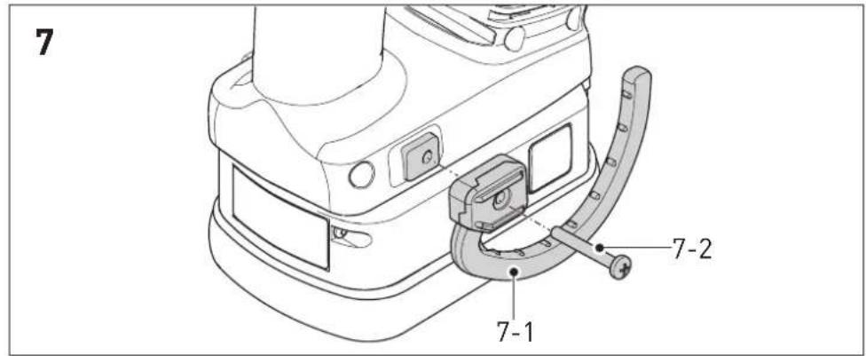
The screwdriver is equipped with a scaffolding holder [7-1] which is used for occasional machine suspension. It can be attached to the left or right of the power tool, by means of a screw [7-2] – see figure [7] .
9.4 Magazine attachment
The magazine attachment enables to work continuously, without unnecessary delays.
Fitting the magazine attachment
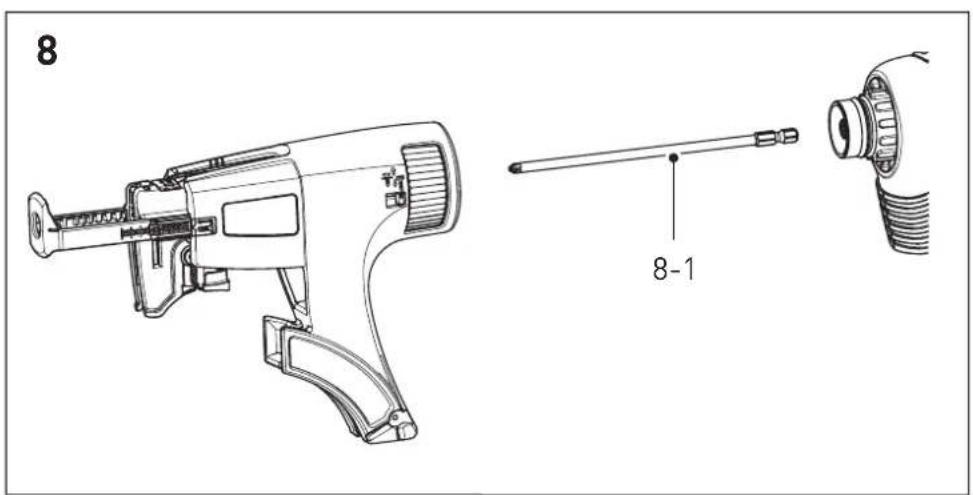
▶ At first remove the depth stopper [4-1] and bit, bit holder [4-2] as specified in chapter 8.
▶ Set the switch[1-4] into MAN position.
▶ Push the long bit[8-1] completely to the hexagonal spindle opening[4-4].
▶ Then fit the magazine attachment on the gear box. Push the attachment until it engages in the groove of the gear box.
▶ The attachment can be mounted at 30^ steps.
Removing the magazine attachment
▶ Use power to carefully pull the magazine attachment from the gear box.
Setting the screw length
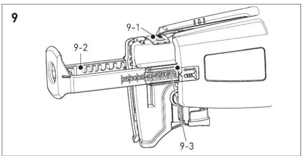
▶ Press button [9-1] to remove and insert the depth stop [9-2] and set the required screw length.
Read the set screw length on the depth stop sides [9-3].
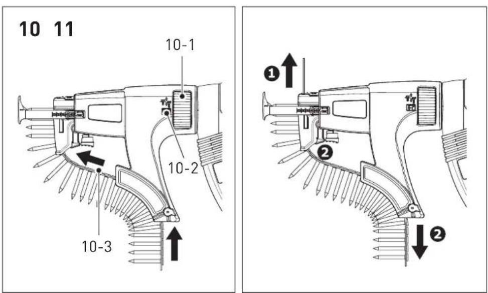
Inserting collated screw strips
▶ Pull the collated screws[10-3] through the bottom guiding of the attachment, then push the strip through the second guiding until it engages in the working position.
Pull the belt slightly to make sure that it is safely fitted.
Make sure that the first screw is in the screwing axes - see figure[10].
▶ Use the wheel[10-1] to set the required screwing depth.
▶ Turn to the right for inserting the screws deeper, and to the left to screw to lower depth. The actual setting position is visible on the presetting indicator [10-2].
Upon setting, set some screws for testing and use the wheel [10-1] to adjust the depth, if required. Each setting change complies with the stop shift o ± 0.1 mm.
① We recommend to screw in automatic mode – see point 9.1 b).
Removing the collated screws
▶ Pull upwards to remove the belt (figure[11] ①) or press the transport lever and concurrently pull the belt downwards (figure[11] ②).
10 Working instructions
- The magazine attachment must not be held in the depth stop area as there are moving parts!
- Each screw adjustment must be completed. Interrupted fastening or releasing of the pressure during adjustment can result in unsatisfactory machine function.
- The collated screws and the magazine attachment can only be replaced when the power tool is turned off.
- Never use the magazine attachment in any other way than specified in this instruction manual.
- Use only original screwing bits.
- Use only original collated screws.
- Always store the collated screws in original packaging.
- Always work in right angle against the attached board.
10.1 Maintenance of the magazine attachment
The attachment generally does not require any maintenance. After long period use, we recommend to clean with pressurized air.
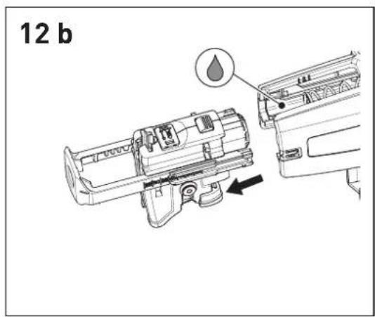
The magazine attachment may be lubricated in the area of the carriage guide (see picture[12b]).
Prior to cleaning, dismantle the attachment, as specified above.
Prior to cleaning, remove the collated screws from the attachment, as specified in the chapter 9.4 point
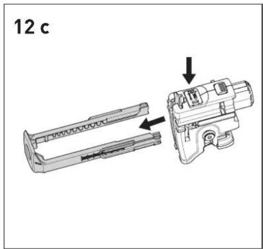
Pull the magazine attachment from the drywall screwdriver.
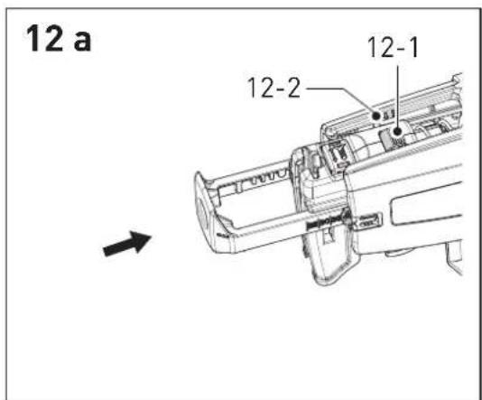
Disassembly of the slides
▶ Push the depth stopper [9-2] into the housing until the arresting button[12-1] is at the level of the sign for dismantling the slides [12-2] – see figure [12a].
▶ Press the arresting button [12-1] and concurrently remove the slides from the holder – see figure [12b].
▶ Press the button[9-1] and concurrently release the depth stopper – see figure[12c].
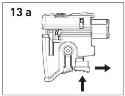
Transport lever disassembly
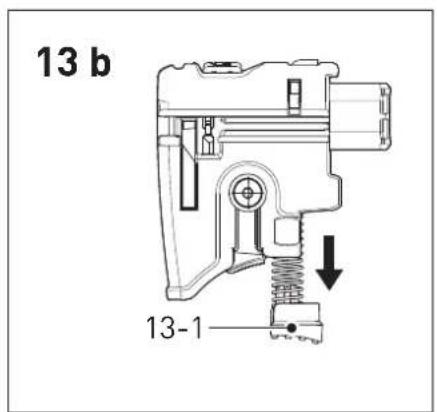
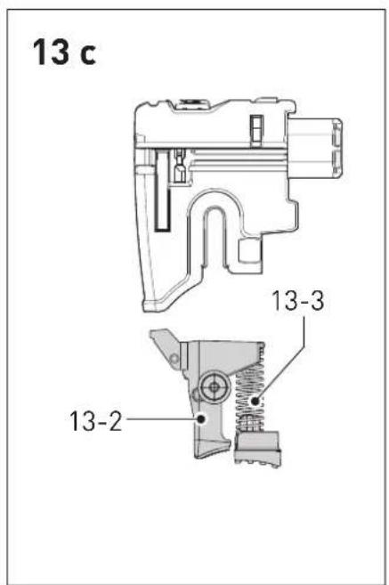
▶ Press the button[13-1] and concurrently pull it out – see figure [13a].
▶ Remove the released button [13-1] (figure [13b]) with the transport lever [13-2] and the spring [13-3] from the slides (figure[13c]).
▶ Clean individual parts, replace defective or worn parts, and assemble in the opposite sequence.
During reassembly of the transport lever into the slides, pay due care to correct fitting of the spring [13-3] in the transport lever. In-correct assembly may result in dysfunction of the belt transport.
10.2 Acoustic warning signals
Acoustic warning signals sound and the machine switches off in the following operating states:

peep — —
Battery flat or machine overloaded.
- Change the battery.
- Place the machine under reduced stress.

peep peep —
Machine is overheating.
- You must allow the machine to cool before using again.

peep peep peep
Lilon battery pack is faulty or has overheated.
- Once the battery pack has cooled, perform a functional check using the charger.
11 Service and maintenance


WARNING
Risk of injury, electric shock
▶ Always disconnect the battery pack from the machine before any maintenance or care work!
▶ All maintenance and repair work which requires the motor housing to be opened, must only be carried out by an authorised service workshop.

Customer service and repair only through manufacturer or service workshops: Please find the nearest address at: www.festool.com/service
Use only original Festool spare parts! Order No. at: www.festool.com/service
Note the following information:
- Keep the ventilation slits on the machine free and clean to ensure adequate cooling.
- Keep the contacts on the machine, charger and battery pack clean.
Information on battery packs
- Store in a cool, dry place at a temperature between 5^ and 25^ .
- Protect battery packs from moisture, water and heat.
- Do not leave flat battery packs in a charger disconnected from the mains power supply for longer than one month. Danger of deep discharge!
- If you intend to store li-ion battery packs for longer periods without use, you should charge them to 40 % capacity (approx. 15 min charging time).
- To avoid short circuits the battery pack should be stored in the packaging supplied.
– Significantly shorter operating times after each charge indicate that the battery pack is worn and should be replaced with a new one.
12 Environment
Do not dispose of the device in household waste! Recycle devices, accessories and packaging. Observe applicable national regulations.
EU only: In accordance with European Directive on waste electrical and electronic equipment and implementation in national law, used electric power tools must be collected separately and handed in for environmentally friendly recycling.
Return used or faulty battery packs to your local specialist retailer, Festool after-sales service or nearest public waste management facility (observe applicable regulations). Batteries must be discharged on return. Battery packs will then be recycled.
EU only: In accordance with the European Directive on batteries and implementation in national law, defective or used battery packs/batteries must be collected separately and handed in for environmentally friendly recycling.
Information on REACH: www.festool.com/reach
13 Transport
The lithium-ion batteries are subject to the requirements of the legislation on hazardous goods. A li-ion battery pack alone falls below the applicable limit value and certified as per UN manual ST/SG/AC.10/11/rev. 3 part III, subsection 38.3. However, dangerous goods regulations may apply when several battery packs are transported For shipping by third parties (e.g. air transport or freight forwarding company) special requirements with regard to packaging and labelling must be observed. For the preparation of the package an expert on hazardous goods must be consulted. Please observe any further national regulations.
Only return the battery pack if the housing is undamaged. Tape over the exposed contacts and wrap the battery pack so that it cannot move inside the packaging.
14 EU Declaration of Conformity
| Cordless drywall screwdriver | Serial no |
| DWC 18-2500 | 767850 |
| DWC 18-4500 | 767898 |
| Year of CE mark: 2013 | |
We declare under sole responsibility that this product complies with all the relevant requirements in the following directives, standards and normative documents:
2006/42/EG, 2004/108/EG, 2011/65/EU, EN 60745-1, EN 60745-2-2, EN 55014-1, EN 55014-2.
| Charger | Serial no. |
| TCL 3 | 10002345, 10004911 |
| Year of CE mark: 2013 | |
GB DURADRIVE
We declare under sole responsibility that this product complies with all the relevant requirements in the following directives, standards and normative documents:
2004/108/EC, 2006/95/EC, 2011/65/EU, EN 60335-1, EN 60335-2-29, EN 61000-3-2, EN 61000-3-3, EN 55014-1, EN 55014-2.
Festool GmbH
Wertstr. 20, D-73240 Wendlingen, Germany
ppa. Dr. Johann Stainel
Head of Research, Development and Technical Documentation
2014-11-06
Accupack inbrengen [2 A]
6.3 Accupack laden [3]
Machine is oververhit.
- Na afkoeling kunt u de machine weer in gebruik nemen.

Li-ion-accupack is oververhit of defect.
6.1 Kabeloppvikling for lader [3-2]
![FESTOOL DWC 184500 Li - Kabeloppvikling for lader [3-2] - 1](/content/2026/02/396736/images/2e912ece6f6e0d4fc095fff63ec3439f6b4a1c3f6df58e37355486de60bdc346.jpg)