
POWX1365MB - Saw PowerPlus - Free user manual and instructions
Find the device manual for free POWX1365MB PowerPlus in PDF.
| Product type | Mini plunge circular saw |
| Brand | PowerPlus |
| Model | POWX1365MB |
| Rated voltage | 220-240 V |
| Frequency | 50 Hz |
| Rated power | 600 W |
| Rotational speed | 5500 rpm |
| Blade diameter | 89 mm |
| Max cutting depth (softwood) | 28.5 mm |
| Max cutting depth (slate) | 8 mm |
| Max cutting depth (aluminum) | 3 mm |
| Laser generator | Yes, with switch |
| Protective guard | Tiltable |
| Dust extraction | Yes, hose included |
| Miter support | Included (adjustable 0-60°) |
| Blades included | 3 (wood, diamond, high-speed steel) |
| Protection class | II (double insulation) |
| Warranty | 36 months |
| Maintenance | Regular cleaning with soft brush |
| Safety | Safety lock, protective guard |
| Commonly cut materials | Wood, aluminum, tile, stone |
Frequently Asked Questions - POWX1365MB PowerPlus
User questions about POWX1365MB PowerPlus
0 question about this device. Answer the ones you know or ask your own.
Ask a new question about this device
Download the instructions for your Saw in PDF format for free! Find your manual POWX1365MB - PowerPlus and take your electronic device back in hand. On this page are published all the documents necessary for the use of your device. POWX1365MB by PowerPlus.
USER MANUAL POWX1365MB PowerPlus
1x support a onglets

10/03/2021, Lier - Belgium
1 APPLICATION 3
2 OVERVIEW COMPONENTS: MINI SIRCULAR SAW (FIG A) ......3
3 OVERVIEW COMPONENTS: MITRE BASE (FIG. B) 3
4 PACKAGE CONTENT LIST 3
5 SYMBOLS 4
6 GENERAL POWER TOOL SAFETY WARNINGS 4
6.1 Work area 4
6.2 Electrical safety 4
6.3 Personal safety 5
6.4 Power tool use and care 5
6.5 Service 6
7 SPECIFIC SAFETY WARNINGS FOR CIRCULAR SAWS.6
8 ASSEMBLY 6
8.1 Setting the cutting depth (Fig .1). 6
8.2 Changing a saw blade 6
9 OPERATION 7
9.1 Holding and switching ON/OFF 7
9.1.1 Switching on the tool: 7
9.1.2 Releasing the plunge stop 7
9.2 Setting the guide fence 7
9.3 Laser line generator 7
9.4 Line following. 8
9.5 Dust extraction 8
10 CUTTING 8
11 CUT-OUTS 9
12 CUTTING PARTICULARLY TOUGH OR ABRASIVE MATERIALS 9
12.1 Sheet metal: 9
12.2 Ceramic tiles, slates etc: 9
12.3 Plasterboard: 9
13 MITRE BASE. 10
13.1 Cutting angle adjustment 10
13.2 Installing and adjusting the clamp 10
13.3 Adjusting position of work platform with angle scale (22) 10
13.4 Cutting with workbench 11
14 CLEANING AND MAINTENANCE 11
14.1 Blades 12
15 TECHNICAL DATA 12
16 NOISE 12
17 WARRANTY 13
18 ENVIRONMENT 13
19 DECLARATION OF CONFORMITY 14
MINI CIRCULAR SAW 600W + MITRE BASE POWX1365MB
1 APPLICATION
This machine is primarily intended for the sawing, longitudinally and transversely, of solid wood, chipboard, plywood, aluminium, tiles and stone held in a fixed position. Please note that the blade pre-installed in the saw as supplied is intended for use with wood only. Any other use or modification to the device shall be considered as improper use and could give rise to considerable dangers. Not suitable for commercial use.

WARNING! Read this manual and general safety instructions carefully before using the appliance, for your own safety. Your power tool should only be passed on together with these instructions.
2 OVERVIEW COMPONENTS: MINI SIRCULAR SAW (FIG A)
- Laser generator
- Laser generator switch
- Safety lock button for mechanical plunge stop
- Cutting depth scale
- ON/OFF switch trigger
- Lock-off button
- Cutting depth setting clamp with lock lever
-
Clamping screw with plain washer
-
Saw blade
- Guide fence slot
- Lock screw for guide fence
- Tiltable protective cover
- Storage for hexagon wrench
- LED Power-on indicator
- Soft grip
- Spindle lock button
- Dust extraction nozzle
- Base plate
3 OVERVIEW COMPONENTS: MITRE BASE (FIG. B)
- Guide rails
- Clamp
- Lock lever for litre scale
- Work platform with angle scale
- Extension rod with extended unction
- Tiltable support
-
-60^ 0^ / 0^ 60^ angle scale
-
0^ 45^ angle scale
- Scale window
- Pointer
- Mounting column clamp
- Lock knob
4 PACKAGE CONTENT LIST
- Remove all packing materials.
- Remove remaining packaging and transit supports (if existing).
- Check the completeness of the packing content.
- Check the appliance, the power cord, the power plug and all accessories for transportation damages.
- Keep the packaging materials as far as possible till the end of the warranty period. Disposet it into your local waste disposal system afterwards.

WARNING Packing materials are no toys! Children must not play with plastic bags! Danger of suffocation!
1x tool 1x manual
POWX1365MB EN
1x saw blade with hardened metal teeth
(A): suitable for: softwood, hardwood, boards of all type
1x diamond saw blade (D): suitable for: ceramic, tile
1x HSS saw blade (E): suitable for: soft metal, aluminium
1x dust extraction hose (B)
1x inner hexagon wrench (F)
1x guide fence (G)
1x litre base

When parts are missing or damaged, please contact your dealer.
5 SYMBOLS
In this manual and/or on the machine the following symbols are used:
| ! | Denotes risk of personal injury or damage to the tool. | Class II - The machine is double insulated; Earthing wire is therefore not necessary. | |
| Read the manual carefully before use. | Always wear safety goggles. | ||
| CE | In accordance with essential requirements of the European directive(s). | Wear gloves. |
6 GENERAL POWER TOOL SAFETY WARNINGS
Read all safety warnings and all instructions. Failure to follow all warnings and instructions may result in electric shock, fire and/or serious injury. Save all warnings and instructions for future reference. The term "power tool" in the warnings refers to your mains operated (cored) power tool or battery operated (cordless) power tool.
6.1 Work area
- Keep work area clean and well lit. Cluttered and dark areas invite accidents.
- Do not operate power tools in explosive atmospheres, such as in the presence of flammable liquids, gases or dust. Power tools create sparks which may ignite the dust or fumes.
- Keep children and bystanders away while operating a power tool. Distractions can cause you to lose control.
6.2 Electrical safety

Always check that the power supply corresponds to the voltage on the rating plate.
- Power tool plugs must match the outlet. Never modify the plug in any way. Do not use any adapter plugs with earthed (grounded) power tools. Unmodified plugs and matching outlets will reduce risk of electric shock.
- Avoid body contact with earthed or grounded surfaces such as pipes, radiators, ranges and refrigerators. There is an increased risk of electric shock if your body is earthed or grounded.
- Do not expose power tools to rain or wet conditions. Water entering a power tool will increase the risk of electric shock.
POWX1365MB EN
- Do not abuse the cord. Never use the cord for carrying, pulling or unplugging the power tool. Keep cord away from heat, oil, sharp edges or moving parts. Damaged or entangled cords increase the risk of electric shock.
- When operating a power tool outdoors, use an extension cord suitable for outdoor use. Use of a cord suitable for outdoor use reduces the risk of electric shock.
- If operating a power tool in a damp location is unavoidable, use a residual current device (RCD) protected supply. Use of an RCD reduces the risk of electric shock.
6.3 Personal safety
- Stay alert, watch what you are doing and use common sense when operating a power tool. Do not use a power tool while you are tired or under the influence of drugs, alcohol or medication. A moment of inattention while operating power tools may result in serious personal injury.
- Use safety equipment. Always wear eye protection. Safety equipment such as dust mask, non-skid safety shoes, hard hat, or hearing protection used whenever conditions require will reduce personal injuries.
- Avoid accidental starting. Ensure the switch is in the off position before plugging in. Carrying power tools with your finger on the switch or plugging in power tools that have the switch on invites accidents.
- Remove any adjusting key or wrench before turning the power tool on. A wrench or a key left attached to a rotating part of the power tool may result in personal injury.
- Do not overreach. Keep proper footing and balance at all times. This enables better control of the power tool in unexpected situations.
- Dress properly. Do not wear loose clothing or jewellery. Keep your hair, clothing and gloves away from moving parts. Loose clothes, jewellery or long hair can be caught in moving parts.
If devices are provided for the connection of dust extraction and collection facilities, ensure these are connected and properly used. Use of these devices can reduce dust related hazards.
6.4 Power tool use and care
- Do not force the power tool. Use the correct power tool for your application. The correct power tool will do the job better and safer at the rate for which it was designed.
- Do not use the power tool if the switch does not turn it on and off. Any power tool that cannot be controlled with the switch is dangerous and must be repaired.
- Disconnect the plug from the power source before making any adjustments, changing accessories, or storing power tools. Such preventive safety measures reduce the risk of starting the power tool accidentally.
- Store idle power tools out of the reach of children and do not allow persons unfamiliar with the power tool or these instructions to operate the power tool. Power tools are dangerous in the hands of untrained users.
- Maintain power tools. Check for misalignment or sticking of moving parts, breakage of parts and any other condition that may affect the power tool's operation. If damaged, have the power tool repaired before use. Many accidents are caused by poorly maintained power tools.
- Keep cutting tools sharp and clean. Properly maintained cutting tools with sharp cutting edges are less likely to stick and are easier to control.
- Use the power tool, accessories and tool bits etc., in accordance with these instructions and in the manner intended for the particular type of power tool, taking into account the working conditions and the work to be performed. Use of the power tool for operations different from intended could lead to a hazardous situation.
6.5 Service
- Have your power tool serviced by a qualified repair person using only identical replacement parts. This will ensure that the safety of the power tool is maintained.
7 SPECIFIC SAFETY WARNINGS FOR CIRCULAR SAWS
- Keep hands away from cutting area and blade. Keep your second hand on auxiliary handle or motor housing.
- Do not reach underneath the workpiece.
- Adjust the cutting depth to the thickness of the workpiece.
- Never hold piece being cut in your hands or across your leg. Secure the workpiece to a stable platform.
- Hold power tool by insulated gripping surfaces when performing an operation where the cutting tool may contact hidden wiring or its own cord.
- When ripping always use a rip fence or straight edge guide.
Always use blades with correct size and shape (diamond versus round) of arbor holes. - Never use damaged or incorrect blade washers or bolt.
- Don't use any abrasive wheels with this machine!
- Avoid overheating the blade tips during use!
- This tool should always be used with the dust hose connected and attached to a suitable vacuum cleaner/dust extractor.
8 ASSEMBLY
8.1 Setting the cutting depth (Fig .1)

NOTE: If possible we recommend that the cutting depth is set approximately 2 mm deeper than the material thickness. This should help to ensure you achieve a clean cut.
Unclamp the lock lever of the cutting depth setting clamp (7), set the required cutting depth on the scale (4) and re-clamp the lock lever.
8.2 Changing a saw blade

WARNING: Incorrect positioning of the blade can permanently damage the tool.
- Ensure the tool is unplugged from the mains supply.
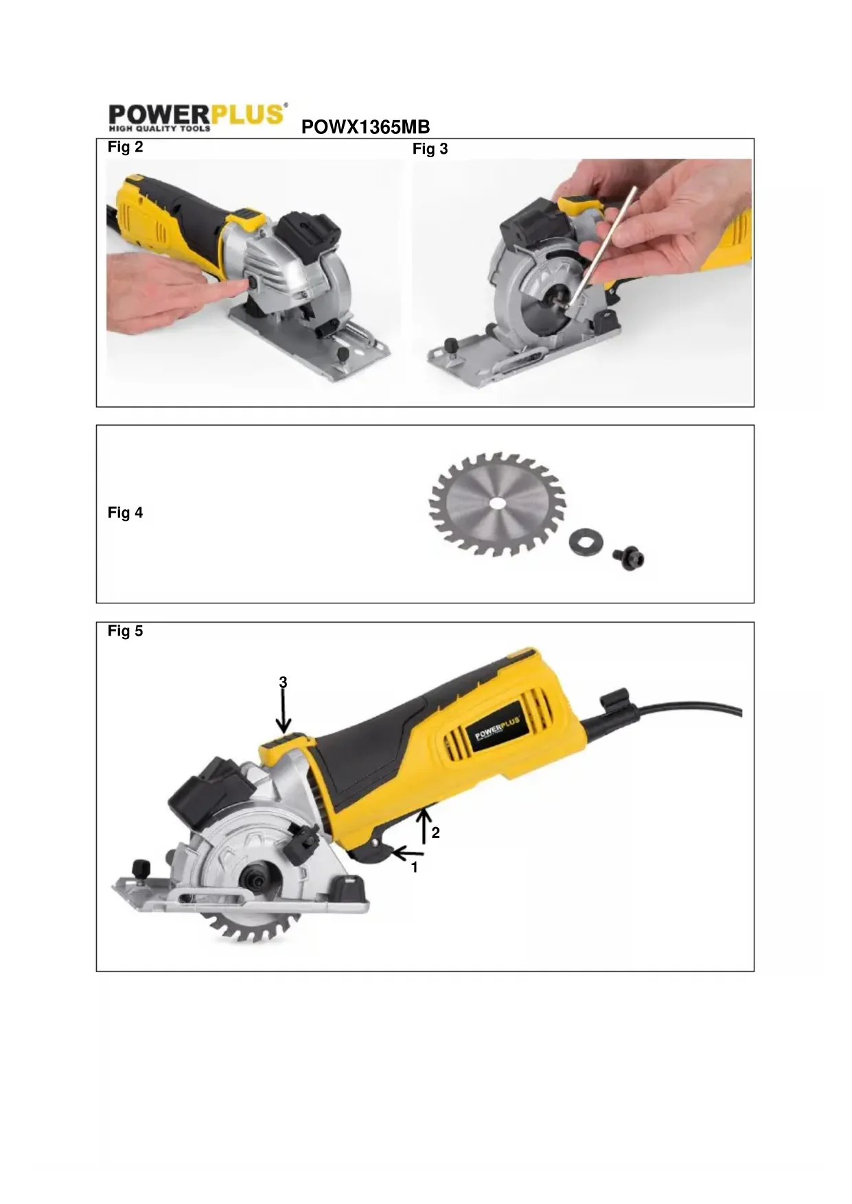
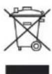
- Press and hold the spindle lock button (16) on, release the clamping screw with plain washer (8) by using the inner hexagon wrench (f) (turn clockwise to open). Remove the clamping screw with plain washer (see Fig. 2, 3 and 4).
- Set the cutting depth to the maximum. (See "Setting the Cutting Depth" section)
- Lift up the base plate (18).
- Remove the saw blade.
- The installation of a saw blade is done in the reverse order.
- Press the spindle lock button (16) (until it engages) and tighten the clamping screw (8) firmly.

NOTE: The arrow on the saw blade must agree with the arrow showing the direction of rotation (running direction shown on the device).
9 OPERATION
9.1 Holding and switching ON/OFF

WARNING: Before engage the ON/OFF switch, check that the saw blade is properly fitted and runs smoothly, and that the blade clamp screw (8) is well tightened.
Connect the plug to the power supply. The LED power-on indicator (14) is illumed until the tool is disconnect from the power mains.
9.1.1 Switching on the tool:
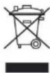
Push the lock-off button (6) forward with the forefinger (refer to the direction of arrow ① on Fig. 5), depress ON/OFF switch trigger (5) firmly inwards and keep it pressed at the same time (refer to the direction of arrow ② on Fig. 5).
When you release the trigger, the main switch returns automatically to initial position and the tool turns off.
Warning: The saw blade continues to rotate after the tool is switched off.
9.1.2 Releasing the plunge stop
Press the rear position of safety lock button (3) downwards and keep it pressed (refer to the direction of arrow ③ on Fig. 5).

NOTE: Pressing the safety lock button (3) unlocks the plunge cut mechanism at the same time, so that the motor can be moved downwards. The saw blade emerges from the tiltable protective cover (12).
9.2 Setting the guide fence
Release the lock screw for guide fence (11) on the base plate (18) and set the guide fence (g) in the guide fence slot (10). Set a desired width and retighten the lock screw for the guide fence (11).
9.3 Laser line generator

Warnings: Do not stare directly at the laser beam, do not deliberately aim the beam at personnel and ensure that it is not directed towards the eye of a person for longer than 0.25s.

When you make the line of the cut on the work piece, the laser line generator can help you get better alignment.
The laser generator switch (2) locates at the front of safety lock button for mechanical plunge stop (3).
Turn on: Press the laser generator switch (2) to "I" position, the laser generator (1) works.
Turn off: Press the switch (2) to "O" position again.
- Make sure line of the cut is on the work piece.
- Adjust the depth of cut as required.
- Plug in the machine and start the motor.
- When the blade is at its maximum speed (approximately 5 seconds), place the saw on the work-piece.
POWX1365MB EN
- Switch on the laser generator (1) from the laser aperture using the laser generator switch (2).
- Align the beam with the mark on the work-piece and slowly push the saw forward using both hands, keeping the red light beam on the mark.
- Switch off the laser beam when completion of the cut.
9.4 Line following
A V-shaped pointer and pointer locate at the front and the rear position of the base plate (18) which allow a line to be followed, when cutting. (Refer to Fig. 6)
9.5 Dust extraction
The circular saw is a powerful tool capable of producing a large amount of dust. As the tool has a fully enclosed blade, forced dust extraction is particularly efficient. Forced dust extraction should be used for all but small trimming jobs.
- Push the dust extraction hose (b) on to the dust extraction nozzle (17).
- Connect a vacuum device approved for the extraction of sawdust and splinters to the dust extraction hose (b).
10 CUTTING

WARNING! Before using the machine, need to check the function of tiltable protective cover (12) can be used properly.

WARNING: Always cut in a forward direction. Never draw the tool backwards. If you are a novice user, practice by cutting thin wood until proficient.
- Check the specifications to ensure the suitability of the material to be cut.
- Fit the correct blade ensuring it is sharp and not damaged.
- Set the depth of cut. (See "Setting the cutting depth" section)
- Place the material to be cut onto a flat surface such as a workbench, table or floor. Use a piece of scrap material underneath it:
- You do not wish to damage the work surface.
- The work surface is likely to damage the blade. E.q. a concrete floor.
- Plug into mains supply.
- Grasp the tool firmly (See "Holding & switching ON/OFF" section) and rest its metal base plate onto the surface to be cut. Ensure that the rear half of the base plate overhangs the work surface. Do not plunge the blade into the material.
- Switch on the tool and wait for a moment for the blade to run up to speed. Next, depress the safety lock button (3) and plunge the blade into the material slowly and gently, but firmly. Then push the tool forwards along the line to be cut. If necessary, switch on the laser generator (1).
NOTE: Never draw the tool backwards. - Very little force should be used to feed the tool along the cut. Excess force will cause operator fatigue and excessive wear to the blade and tool. Excess force is also likely to cause the temperature cut-out to trip, resulting in delays.
- Ensure that the base plate is always held flat on the material being cut. This is particularly important at the start or finish of a cut or if thin strips are being cut where the base plate is not fully supported.
- Once the cut has been finished, lift the tool from the work surface before switching off. If a lot of dust has been created, keep switched on for a few seconds extra to allow the dust to clear from within the tool.
11 CUT-OUTS
- Plunge cutting may not be possible in some hard materials.
- Choose a suitable saw blade for hard materials and change to it. Set the depth of cut (See "Setting the Cutting Depth" section), plug in the mains supply and then place the metal base plate (18) onto the work surface. Ensure that the front indication mark on the base plate aligns with the start line (See "Line Following" section).
- Switch on the tool and wait for a moment for the blade to run up to speed. Next, plunge the blade into the material slowly and gently, but firmly. Then push the tool forwards along the line to be cut. (Never draw the tool backwards)
-
Once the finish line has been reached, lift the tool from the work surface before switching off. If a lot of dust has been created, keep switched on for a few seconds extra to allow the dust to clear from within the tool.
Cutting out tips: -
If the cut is to be covered, for example by a vent cover, the corners can be overlapped to ensure that the waste material is completely detached.
II. If the cut out is to be seen, do not overlap the corners. In this circumstance, as the cutting blade is circular, the waste material will not be fully detached. The corners will therefore, require finishing with a knife. If the material is thin and the back surface unimportant, the waste material can just be pushed out.
III. Where there is access to the back surface of the material to be cut, the cut out can be marked out with an over cutting allowance. The cut is then made from the back surface to ensure perfect corners on the front surface.
12 CUTTING PARTICULARLY TOUGH OR ABRASIVE MATERIALS
Learn to use the tool by cutting wood before attempting to cut anything tougher. When cutting tougher material, such as metals, more force is required to hold the work piece and clamping may be required.
Never cut materials that produce toxic dust or fumes such as PTFE or asbestos.
12.1 Sheet metal:
- Always set the depth adjustment to at least 1mm deeper than the material thickness to avoid the blade riding up over the surface. Scrap material is required underneath the work surface.
- Remove burrs and rust as these impede the feed across the material.
- Thick beeswax (furniture polish) applied to the base plate of the tool makes metal cutting easier.
Only suitable for cutting brass, copper, lead, aluminium or galvanised mild steel. - Every 2 minutes of metal cutting should be followed by a rest of at least 3 minutes.
12.2 Ceramic tiles, slates etc:
- Only use a blade specifically designed for this purpose.
- Always use with a suitable vacuum cleaner or dust extractor connected as the dust can be hazardous to the operator and prevent the guard operating correctly.
12.3 Plasterboard:
-
The plunge saw is only recommended for making occasional cut outs in plasterboard and always us it with a suitable vacuum cleaner or dust extractor connected. The dust can prevent the guard operating correctly.
-
Conventional tools such as keyhole saws or knives generally give excellent results, though the plunge saw can be used if a particularly neat, dust free cut is required or if there is a danger of cutting pipes or cables.
13 MITRE BASE
13.1 Cutting angle adjustment

NOTE: The angle scale (25) shows metre angles from 0^ to 60^ to the left, and 0^ to 60^ to the right.

There are four degree scales is 0^ , 15^ , 30^ and 45^ on the angle scale (26) which these locations represent the most common angles for cutting operation.
Take out clamp (20), lift the lock lever for metre scale (21) and loose extension rod (23).
- If the desired angle is one of the most common angles for cutting, set the right edge of extension rod (23) align scale mark to the required degree measurement on the angle scale (26).

Note: The pointer of the display scale window (27) indicates the above required degree measurement on the angle scale (25) at the same time. (Refer to Fig. 7)
- If the desired angle is not one of the most common angles for cutting, set the pointer (28) of the display scale window (27) align scale mark to the required degree measurement on the angle scale (25).
- Tighten the lock lever (21) and make sure the extension rod (23) fixes firmly.
13.2 Installing and adjusting the clamp
- Place the clamp subassembly (20) on the mounting column clamp(29) of work platform with angle scale (22).

NOTE: There are no screws to secure clamp. The clamp subassembly will secure itself to the work platform (22) when turning the knob to clamp the work-piece.

Do not use your other hand to hold the clamp when tightening. Only turn the knob to secure clamp to work platform.

NOTE: prior to estimate thickness of work-piece, adjust the height of clamp to higher than work-piece which convenient for clamping work-piece quickly.
13.3 Adjusting position of work platform with angle scale (22)
There is a lock knob on (30) the bottom of work platform (22) which adjusts position of work platform at the workbench. Loose the work platform (22) by turning lock knob anticlockwise and slide the work platform to desired position as similar to Fig. 8 shows. Finally tighten the lock knob firmly.
13.4 Cutting with workbench

WARNING: Always cut in a forward direction. Never draw the tool backwards. If you are a novice user, practice by cutting thin wood until proficient.
- Set cutting angle of workbench. (See Cutting angle adjustment Section)
- Place the work-piece onto the workbench and clamp the work-piece with clamp subassembly (20). (See Installing and adjusting the clamp Section)

NOTE: if the length of the work-piece is longer than normal level, you can use extended function of extension rod (23), hold the Tiltable support (24) and pull the extension rod to a suitable position for current work-piece. (Refer to Fig. 9 and Fig. 10)
- Fit the correct blade ensuring it is sharp and not damaged.
- Set the depth of cut. (See Setting the Cutting Depth Section)
- Grasp the tool firmly (See Holding and Switching ON/OFF Section), switch on the tool and wait for a moment for the blade to run up to speed. Next, depress the safety lock button (3) and plunge the blade into the material slowly and gently, but firmly. Then push the tool forwards along the guide rails (19) to be cut.

NOTE: Never draw the tool backwards.
- Once the cut has been finished, lift the tool from the workbench before switching off. If a lot of dust has been created, keep switched on for a few seconds extra to allow the dust to clear from within the tool.

NOTE: if cutting without workbench, you can refer to the below descriptions:
- Check the blade whether is correct and ensuring it is sharp and not damaged.
- Set the depth of cut, switch on the tool and wait for a moment for the blade to run up to speed.
- Depress and hold the safety lock button (3) on, plunge the blade into the material slowly and gently, but firmly.
- Push the tool forwards along the line to be cut. If necessary, switch on the laser generator (1). (Refer to Laser line generator Section)
14 CLEANING AND MAINTENANCE
Regular cleaning is required for the safe operation of the tool, as an excessive build up of dust will prevent the tool from operating correctly.
The dust extraction hose (b) may block and require cleaning occasionally, especially if damp wood is being cut.
- Unplug from mains supply.
- Clean thoroughly with a small soft brush, like a paint brush.
- Keep the cooling vents on the motor housing clean and unobstructed at all times.
- Never use any caustic agents or solvents to clean the plastic parts.
14.1 Blades
Always use a sharp blade.
If the tool does not cut as well as expected or if it overheats (temperature cut out may trip) the most common cause is a blunt blade.
- It is difficult to see or feel if the blade is blunt. When in doubt use a new blade.
- Blades are consumable items.
- Beware when changing blades as they can become hot during use. Allow the blade some time to cool before replacing it.
15 TECHNICAL DATA
| Rated voltage | 220-240 V |
| Rated frequency | 50 Hz |
| Rated power | 600 W |
| Rotation speed | 5500 min-1 |
| Blade size | Ø 89 mm |
| Max. cutting depth soft wood | 26.5 mm |
| Max. cutting depth tile | 8 mm |
| Max. cutting depth aluminum | 3 mm |
16 NOISE
Noise emission values measured according to relevant standard. (K = 3)
Acoustic pressure level LpA 95 dB(A)
Acoustic power level LwA 106 dB(A)

ATTENTION! Wear hearing protection when sound pressure is over 85 dB(A).
aw (Vibration):
2.8 m/s²
K = 1.5 m/s²
17 WARRANTY
This product is warranted as provided by law for a 36 -month period effective from the date of purchase by the first user.
- This warranty covers all material or production flaws excluding : batteries, chargers, defective parts subject to normal wear & tear such as bearings, brushes, cables, and plugs, or accessories such as drills, drill bits, saw blades, etc. ; damage or defects resulting from maltreatment, accidents or alterations; nor the cost of transportation.
- Damage and/or defects resulting from inappropriate use also do not fall under the warranty provisions.
We also disclaim all liability for any bodily injury resulting from inappropriate use of the tool.
- Repairs may only be carried out by an authorised customer service centre for Powerplus tools.
- You can always obtain more information at the number 00 32 3 292 92 90.
- Any transportation costs shall always be borne by the customer, unless agreed otherwise in writing.
- At the same time, no claim can be made on the warranty if the damage of the device is the result of negligent maintenance or overload.
- Definitely excluded from the warranty is damage resulting from fluid permeation, excessive dust penetration, intentional damage (on purpose or by gross carelessness), inappropriate usage (use for purposes for which the device is not suitable), incompetent usage (e.g. not following the instructions given in the manual), inexpert assembly, lightning strike, erroneous net voltage. This list is not exhaustive.
- Acceptance of claims under warranty can never lead to the prolongation of the warranty period nor commencement of a new warranty period in case of a device replacement.
Devices or parts which are replaced under the warranty therefore remain the property of Varo NV
- We reserve the right to reject a claim whenever the purchase cannot be verified or when it is clear that the product has not been properly maintained. (Clean ventilation slots, carbon brushes serviced regularly, etc.).
- Your purchase receipt must be kept as proof of date of purchase.
- Your appliance must be returned undismantled to your dealer in an acceptably clean state, (in its original blow-moulded case if applicable to the unit), accompanied by proof of purchase.
18 ENVIRONMENT
Should your appliance need replacement after extended use, do not discard it with the household rubbish but dispose of it in an environmentally safe way. Waste produced by electrical machine items should not be handled like normal household rubbish. Please recycle where recycle facilities exist. Check with your Local Authority or retailer for recycling advice.
VARO N.V. - Vic. Van Rompuy N.V. Joseph Van Instraat 9 - BE2500 Lier - BELGIUM, declares that,
Product: Mini circular saw 600W
Trade mark: POWERplus
Model:POWX1365MB
is in conformity with the essential requirements and other relevant provisions of the applicable European Directives, based on the application of European harmonized standards. Any unauthorized modification of the apparatus voids this declaration.
European Directives (including, if applicable, their amendments up to the date of signature):
2011/65/EU
2006/42/EC
2014/30/EU
European harmonized standards (including, if applicable, their amendments up to the date of signature):
EN62841-1:2015
EN62841-2-5:2014
EN55014-1:2017
EN55014-2:2015
EN IEC61000-3-2:2019
EN61000-3-3:2013
Keeper of the Technical Documentation : Philippe Vankerkhove, VARO - Vic. Van Rompuy N.V.
The undersigned acts on behalf of the company CEO,
Mertens Ludo
Ludo Mertens
Regulatory Affairs - Compliance Manager
10/03/2021, Lier - Belgium
10/03/2021, Lier - Belgium
Regulatory Affairs - Compliance Manager
10/03/2021, Lier - Belgium
1 APLICACAO 3
2 VISTA GERAL DOS COMPONENTES: MINI SERRA CIRCULAR (FIG. A) 3
3 VISTA GERAL DOS COMPONENTES: BASE ANGULAR (FIG. B) 3
4 CONTEUDO DA EMBALAGEM 3
5 SIMBOLOS. 4
6 PROCEDIMENTOS GERAIS DE SEGURANCA 4
6.1 Area de trabajo 4
6.2 Seguranca eltrica 5
6.3 Seguranta persona 5
6.4 Manuseamento e lavoro de ferramentas eletricas com precauacao 6
6.5 Assistance Tecnica 6
7 INSTRUÇÉS DE SEGURANÇA ADICIONAIS PARA SERRAS CIRCULARES 6
8 MONTAGEM 7
8.1 Ajustar a profundidade de corte (Fig. 1)
8.2 Substituiruma lamina.. 7
9 OPERACAO 7
9.1 Segurar e LIGAR/DESLIGAR 7
9.1.1 Ligara ferramenta: 7
9.1.2 Soltar o batente de penetracao 8
9.2 Ajustar a guia de protecao 8
9.3 Gerador da linha laser 8
9.4 Acompanhar a LINha 8
9.5 Extração de pó 8
10 CORTAR 9
11ENTALHES 9
12 CORTAR MATERIALS PARTICULARMENTE DUROS OU ABRASIVOS 10
12.1 Folha de metal: 10
12.2 Telhas de ceramica, azulejos, etc: 10
12.3 Gesso cartonado: 10
13 BASE ANGULAR 10
13.1 Ajuste do angulo de corte 10
13.2 Instalar e ajustar o grampo 11
13.3 Ajustar a posicao da plataforma de trabalho com escala angular (22) 11
13.4 Cortar com banca de trabajo 11
14 LIMPEZA E MANUTENCAO 12
14.1 Laminas 12
15 DADOS TECNICOS 13
16 RUIDO 13
17 GARANTIA 13
18 MEIO-AMBIENTE 14
19 DECLARACAO DE CONFORMIDADE 14
MINI SERRA CIRCULAR 600 W + BASE ANGULAR POWX1365MB
1 APLICACAO
1x chave sextavada interior (F)
10/03/2021, Lier - Belgium
1 BRUKSOMRADE 3
2 OVERSIKT OVER KOMPONENTER: MINISIRKELSAG (FIG. A)..3
3 OVERSIKT OVER KOMPONENTER: GJAERINGSANLEGG (FIG. B) 3
4 PAKKENS INNHOLD 3
5 SYMBOLER 4
6 GENERELLE SIKKERHETSADVARSLER 4
6.1Arbeidsplassen 4
6.2 Elektrisk sikkerhet 4
6.3 Personsikkerhet 5
6.4 Vær noyaktig og omhyggelig nár du omgås elektroverktoy 5
6.5 Service 5
7 ANBEFALTE SIKKERHETSREGLER FOR SIRKELSAGER...6
8 MONTASJE 6
8.1 Stille inn sagdybden (Fig. 1)
8.2 Skifte sagblad.. 6
9 BRUK. 7
9.1 Holde verktoyet og sla P/AV 7
9.1.1 Sla pa verktoyet: 7
9.1.2 Frigjore dybdestoppen 7
9.2 Stille inn styringsanslaget 7
9.3 Laserstralen 7
9.4 Følge en strek 8
9.5 Stovavssug. 8
10 SAGING 8
11UTSKJAERINGER. 9
12 SAGING AV SPESIELT HARDE ELLER UJEVNE MATERIALER 9
12.1 Platemetall: 9
12.2 Keramiske fliser, heller osv.: 9
12.3 Gipsplater: 9
14 RENGJØRING OG VEDLIKEHOLD
10/03/2021, Lier - Belgium
1 ANVENDELS
2 BESKRIVELSE: MINI-RUNDSAV (FIG. A) 3
3 OVERSIGT OVER GERINGSSTATIONENS KOMPONENTER (FIG. B) 3
4 MEDFØLGENDE INDHOLD 3
5 SYMBOLER 4
6 ALMINDELIGE SIKKERHEDSANVISNINGER FOR EL-VAERKTØJ
10/03/2021, Lier - Belgium
10/03/2021, Lier - Belgium
1 EΦAPMOrH 3
2 ΠΕΡΑΦΗ ΕΕAPTHMATΩΝ: MINI KYΚΑΙΚΟ ΠΡΙΝΙ (EIK. A).3
3 έNEPIΓPAΦH EΞAPTHMATΩN: BAΣH ΦΑΛΤΟΓΩNIAΣ (EIK. B) 3
4 ΛIΣTA ΠΕΠΕXΟΜΕΝΟ ΣΥΣΚΕYΑΣΙΑΣ 3
5 SYMBOAA 4
6 TENIKE Σ ΠPOEΙΔΟΝΙΗ ΕΙΣ ΑΣΦΑΛΕΙΑΣ ΓΙΑ TA HΑEKΤΡΙΚA EΓΑΛΕΙΑ 4
6.1 Xwpoc epyaos
6.2 Hεκτρική ασφάλεια 5
6.3 Atoiikn aovapaleia 5
6.4 Xpnoa kai povtia rwo nAekpiikwv epyaAeiwV 6
6.5 2ερβις
7 IPOsOETE OADHIEAΦAIAIg IA DIKONPIONA 6
8 SYNAPMOAOH
8.1 PuOiOtn rou aOouc KOnns (Eik. 1)
8.2 Aaayn nC npiovlaep
9 AEITOYPIA 7
9.1 Kpatnua kai /
9.1.1 ΘeON e λειουργia tou εργαλείου: 7
9.1.2 ATEeUePomegaTnc unxavikns payns BuOioans.. 8
9.2 Kpatnma kai Eekivnma/otapatnma 8
9.3 8
9.4 AkoIoouoIOn Tns ypaumc Konns 8
9.5 Exiaywyn oKovns 8
10 KONH 9
11 ANOKONH 10
12 KONH IIAITEPA ΣKΛHPQN ḋ ΑΕIANTIKΩN YAIKΩN 10
12.1 Aapapiva: 10
12.2 Kepaikia PAAkacia, oioToAio kA.. 10
12.3 Furooavla: 11
13 BAeH 4AANTcOgNIAE 11
13.1 Puroion ts yovia c konns 11
13.2 Eykaradostao n kalpuoioan rou ophiyknipa 11
13.3 Pooion ts eon ts emapveiae pyaoiae klapaka ywviae (22) 12
13.4 Konj navw onn baoon paalrooywviac 12
14 KAoAPIeMOs KAI yNTHPHsH 13
14.1 Aεπiδεζ 13
15 TEXNIKA XAPAKTHPIETIKA 13
16 0OPYBOE 13
17 ERTYH
18 IEPIBAON 14
19 AHAN2EH SYMMOPΦΩ2H
MINI KYKAIKO IPIONI 600W + BA∑H ΦAANTΣOΓΩNIAZPOWX1365MB
1 EΦAPMÖΓ
AutoTo uynxavma TPOOPIcTai KupiwC yia TPIOVioa, kata mnkoc kai Eykapoi, oTepeou Euou, voBottav, Kovtpa TAAke, aoumuivou, TALakiowv kai TETpac Tou KpatiouTai Oe Otaepn Theon. 2neiwoTE otI n LEITIDA Tous exei TPOEYkataotaThei OTO Tpiovki Kata Tnv Tnapadoon TPOOPIcTai yia xpono mvo e Lua. OTIOAdbntote aALn Xpnon n TpoTOninon Tou uynxavnuatoC th a Ewnpthe ioepaalvev n xpnon kai mtopei va dnoiupynoeikivouc. Ev evai katalnnlo yia emtropikn xpnon.

IPOEIAONOIHSH! Ia Tn Dikn Oac aopaleia, diaaote TpooeKTiKa auto To EYxepio kai TIC YEVIKec oOnyiec aopaleia cTPIV XpnoipotoineTe to mXavna. Av dwoete TO nAektpiko epyaleio e allo xpntn, 0a TpeTt va dwoete ma zi kai autc Tc odnyies.
10/03/2021, Lier - Belgium
1 PRIMJENA 3
2 OPIS: MINI KRUZNA PILA (SLIKA A) 3
3 OPIS: DRZACA ZA IZREZIVANJE POD KUTOM (SLIKA B) 3
4 POPIS SADRžAJA PAKETA 3
5 SIMBOLI 4
6 OPÇA UPOZORENJA O SIGURNOSTI RUKOVANJA
ELEKTRICNIM ALATIMA 4
6.1 Radno mesto 4
6.2 Elektricna sigurnost 5
6.3 Osobna sigurnost 5
6.4 Uporaba i odrzavanje elektricnog alata 5
6.5 Servis 6
7 POSEBNA SIGURNOSNA UPOZORENJA ZA KRUZNE PILE 6
8 SKLAPANJE 6
8.1 Postavljanje dubine rezanja (slika 1) 6
8.2 Promjena lista pile 7
9 RAD 7
9.1 Drzanje, uključivanje i isključivanje 7
9.1.1 Uključivanje alata: 7
9.1.2 Oslobadanje ubodnog graničnika 7
9.2 Postavljanje granicne vodilice 8
9.3 Generator laserske crte 8
9.4 Pracenje crte 8
9.5 Izvlačenje prăšine 8
10 REZANJE 8
11 IZREZIVANJE 9
12 IZREZIVANJE POSEBNO TVRDIH ILI ABRAZIVNIH MATERIJALA10
12.1 Metalni lim: 10
12.2 Keramičke pločice, škriljac i sl: 10
12.3 Gipsane ploche: 10
13 DRZAC ZA IZREZIVANJE POD KUTOM 10
13.1 Podesavanje kuta izrezivanja 10
13.2 Ugradnja i podesavanje stezača 11
13.3 Podesavanje poloza radne podloge skutomjerom (22) 11
13.4 Rad na radnoj povrsini 11
14 CIsCENJE I ODRZAVANJE 12
14.1 Listovi pile 12
15 TEHNICKI PODACI 12
16 BUKA 12
17 JAMSTVO 13
18 OKOLIŠ 13
19 IZJAVA O SUKLADNOSTI 14
MINI KRUŽNA PILA 600 W + DRŽAĆ ZA IZREZIVANJE POD KUTOM POWX1365MB
1 PRIMJENA
Stroj je prvenstveno namijenjen piljenju, uzduznom i poprečnom, tvrdog drveta, iverice, sperploče, aluminija, pločica i kamera učvršćenih u stalnom položaju. Primijetite da je nož koji je postavljen u isporučenu pilu namijenjen za upotrebu samo za drvo. Bilo koji drugi način uporabe ili preinaka urežaja smatratće se nepravilnom uporabom i može predstavljati značajnu opasnost. Nije namijenjeno za komercijalnu uporabu.

UPOZORENJE! Prije uporabe alata, a radi vase vlastite sigurnosti pažljivo procitajte ovaj prisucnik i opce upute o sigurnosti. Ove upute cine sastavni dio opreme elektricnog alata, pa i u slučaju prodaje drugom vlasniku.
2 OPIS: MINI KRUZNA PILA (SLIKA A)
1 Generator lasera
2 Sklopka generatora lasera
3 Sigurnosni gumb za blokadu mehaničkog ubodnog graničnika
4 Mjerilo dubine rezanja
5 Gumb sklopke za uključivanje i isključivanje
6 Gumb za otključavanje
7 Stezaljka za postavljanje dubine rezanja s ručicom za blokadu
8 Vijak stezaljke s ravnom podloznom plocicom
9 List kružne pile
10 Utor granicne vodilice
11 Vijak za blokadu za graničnik vodilice
12 Nagibni zašitniPoklopac
13 Spremieste za šesterobridni ključ
14 LED indicator napajanja
15 Mekirukohvat
16 Gumb za blokadu osovine
17 Mlaznica za isisavanje prasine
18 Ploča stalka
3 OPIS: DRZACA ZA IZREZIVANJE POD KUTOM (SLIKA B)
19 Vodilice
25Kutomjer -60^ 0^ / 0^ 60^
20 Stezač
26 Kutomjer 0^ 45^
10/03/2021, Lier - Belgium
1 PRIMENA 3
2 PREGLED KOMPONENTI: MINI KRUZNA TESTERA (SL. A) 3
3 PREGLED KOMPONENTI: POSTOLJE ZA KOSO SEÇENJE (SL. B) 3
4 SPISAK SADRZAJA PAKOVANJA 3
5 SIMBOLI 4
6 OPŠA BEZBEDNOSNA UPUTSTVA ZA ELEKTRICNE ALATE... 4
6.1 Radna oblast 4
6.2 Elektricna bezbednost 4
6.3 Lična bezbednost 5
6.4 Korisćenje i održavanje elektrčnog alata 5
6.5 Servisiranje 6
7 POSEBNA BEZBEDNOSNA UPOZORENJA ZA KRUŽNE TESTERE 6
8 SKLAPANJE 6
8.1 Postavljanje dubine secenja (SI. 1) 6
8.2 Zamena lista testere 6
9 RAD 7
9.1 Drzanje i uključivanje/isključivanje 7
9.1.1 Uključivanje alata u rad: 7
9.1.2 Otpustanje graničnika za uranjanje 7
9.2 Postavljanje granichika 7
9.3 Generator laserske linije 8
9.4 Pracenje linije 8
9.5 Odstranjivanje prašine 8
10 SEcENJE 8
11 ISECANJE 9
12 SEÇENJE IZUzetNO ZILAVIH ILI ABRAZIVNIH MATERIJALA.... 9
12.1 Metalni limovi: 10
12.2 Keramičke pločice, škriljac, itd.: 10
12.3 Gipsane ploche: 10
13 POSTOLJE ZAKOSO SEÇENJE 10
13.1 Podesavanje ugla secenja 10
13.2 Postavljanje i podesavanje stege 10
13.3 Podesavanje poloza radne povrsine sa ugaonom skalom (22) 11
13.4 Sechenje sa radnim stolom 11
14 CIscENJE I ODRZAVANJE 12
14.1 Listovi testere 12
15 TEHNICKI PODACI 12
16 BUKA 12
17 GARANCIJA 13
18 ZIVOTNA SREDINA 13
19 IZJAVA O USKLADENOSTI 14
MINI KRUZNA TESTERA 600 W SA POSTOLJEM ZA KOSO SEČENJE POWX1365MB
1 PRIMENA
Ova mašina je prvenstveno namenjena za sečenje, podužno i poprečno, punog driveta, iverice, sperploče, aluminijuma, pločica i kamena koji se drže u fiksiranom položaju. Imajte u vidu da je list koji se nalazi u testeri prilikom isporuke namenjen samo za upotrebu sa drivetom. Bilo koja drugacija upotreba ili modifikacije ovg uredja ce se smatrati nepravilnom upotrebom i mogu prouzrokovati znatnu opasnost. Ovaj alat nije pogodan za komercijalnu upotrebu.

10/03/2021, Lier - Belgium
1 OBLASTPOUZITI 3
2 POPIS: MINI OKRUZNI PILA (OBR. A) 3
3 PREHLED KOMPONENT POKOSOVZAKLADNY (OBR.B)....3
4 SEZNAM OBSAHU BALENI 3
5 SYMBOLY 4
6 OBEÇNA BEZPEČNOSTNI UPOZORNÉNÍ PRO ELEKTRICKÉ NASTROJE 4
9.1 Pridrzeni a prepnutI ON/OFF

13.4 Rezani's pracovnim stolem

10/03/2021, Lier - Belgium
1 DOMENII DE UTILIZARE 3
2 PREZENTARE GENERALÄ COMPONENTE: MINIFERÄSTRÄU CIRCULAR (FIG. A) 3
3 PREZENTARE GENERALÀ A COMPONENTELOR SUPORTULUI DE TAIERE IN UNGHI ASCUÇIT 3
4 CONTINUTUL PACHETULUI 3
5 SIMBOLURI 4
6 AVERTISMENTE GENERALE DE SIGURANÀ PRIVIND APARATUL ELECTRIC 4
6.1 Zona de lucru 4
6.2 Siguranţa electrică 5
6.3 Sigurantha personala 5
6.4 Folosirea 山 intretnerea aparatului electric.. 5
6.5 Service 6
7 AVERTISMENTE SPECIFICE DE SIGURANÀ PENTRU FERÄSTRAIELE CIRCULARE 6
8 MONTAREA 6
8.1 Reglarea adancimii de taiere (Fig. 1). 6
8.2 Schimbarea discului ferastrului 7
9 MOD DE UTILIZARE 7
9.1 Apucarea si pornirea si oprirea 7
9.1.1 Pornirea aparatului: 7
9.1.2 Eliberareaopritorului deplonjare 7
9.2 Reglarea grilajului de ghidare 8
9.3 Generatorul fasciculului laser 8
9.4 Urmairrea liniei 8
9.5 Extragerea prafului 8
10 TAIEREA 8
11 DECUPAJELE 9
12 TAIEREA MATERIALDURE SAU ABRAZIVE 10
12.1 Tabla: 10
12.2 Placile ceramicice, gresia etc.: 10
12.3 Ghips-carton: 10
13 SUPORT DE TAIERE IN UNGHI ASCUTIT. 10
13.1 Reglarea unghiului de taiere 10
13.2 Montarea 山 reglarea clementi 11
13.3 Reglarea pozitiei platformei de lucru cu raportor (22) 11
13.4 Tajierea pe bancul de lucru 11
14 CURATAREA SINTRETINEREA 12
14.1 Discurile 12
15 DATE TEHNICE 12
16 ZGOMOT 13
17 GARANTIE 13
18 MEDIU 14
19 DECLARATIA DE CONFORMITATE 14
MINIFERÁSTRÁU CIRCULAR 600 W + SUPORT DE TÄIERE IN UNGHI ASCUTIT POWX1365MB
1 DOMENII DE UTILIZARE
10/03/2021, Lier - Belgium
1 ZASTOSOWANIE 3
2 PRZEGLAD CZESCI: MINIPILARKA TARCZOWA (RYC. A) .......3
3 PRZEGLAD CZEŚCI: PODSTAWA DO CIECIA UKOSNEGO (RYC. B) 3
4 SPIS CZESCI 3
5 OZNACZENIA 4
6 OGOLNE ZASADY BEZPIECZNEJ PRACY
ELEKTRONARZEDZIAMI 4
10/03/2021, Lier - Belgium
10/03/2021, Lier - Belgium
1 OBlaCTb PIPMEHEHn3
2 O63OP KOMNOHETOB LNPKUJIAPHOI MNH-PIJIbI (PNC. A) 3
3 O63OP KOMNOHEHTOB DEPKATEJIЯ DKOCOB (PNC. B)
4 CODEPJKMOE YNAKOBKN 4
5 YCIOBhIE OBO3HAUHnA 4
6 OBJA HCTPyKcIg IO TEXHnke B3OpACHOCTN PPN PABOTE C 3JIeKTPoHCTPymEHTOM
6.1 Pa6ooye Mecmo 5
6.2 3neKmpo6e30nacHocmb... 5
6.3 5
6.4 3Kcnnnyamauua u yxod 3a 3neKmpouHcmpyMeHmOM
6.5 06cnyxueaHue 6
7 OCObIe MEPbI PPeIOCTOPOXHOCTN IJIa CHPKUJIAPHbIX NII 6
8 C6OPKA 7
8.1 Hacmpoika 2ny6uHb nponuna (Puc. 1)
8.2 Cmeha nulbho 0 ducka
9 3KcPnyATAU8
9.1 YdepxueHue u EKIOyeHue Uu EblKnIOeHue... 8
9.1.1 BkIIOueHHe IHcTpymeHTa 8
9.1.2 OTnyckaHne orpaHnHTeIe BepTKaJIbHoro nepemeueHna 8
9.2 YcmaHo6Ka HnpaenJIOuei PnaHku 8
9.3 Tenepeamop naepnoi nuu.. 8
9.4 Cnedeogahue Juhuu 9
9.5 YdaJIeHue onuJok 9
10 NIIJIeHnE 9
11 BblPE3bl 10
12 ПИЛЕНЕ ТРУДноOBРАБATыIBAEMbIX ИЛN АБР3ИВнБIX MATEРПAJIOB 10
12.1 Iucmosou Memann: 10
12.2 Kepamuueckue numku, wufephble numku u m.d. 11
12.3 FuncokapmoH 11
13 DEPKATEJIb IJIa CKOCOB 11
13.1 Peaynupo6ka yana pe3ku 11
13.2 YcmaHOeKa u peaynupoeKa npuxuma.. 11
13.3 PeaynpoKa nonoKeHna pa6oeu noCmaKu c yanoOou wkaNo (22) 12
13.4 Pe3ka c bepcmaKOM 12
14 YNCTKA N OBCJNYKIBAHNE 13
14.1 13
15 TEXHnueCKNE DAHHbIE 13
16 11YM 14
17 TAPAHTNA 14
18 OKPYKAIUJIACPEDA 15
19 DEKJIAPAUHCAOTBETCTBnA 15
LIPKUYJIAPHAR MHHI-PIJIA 600 BT + DEPJKATEJB DJIYCKOCOBPOWX1365MB
1 OBJACTb IPIPIMEHEHnA
Пла прднэзауен Дпл рpoДьнги Nпоpeчног рacnIOBkn MaccNBHOn DpeBecnbl, IamHnpOBaHHoJ dpeBecnbl, DCN, phapebl, anHOMHn, PnTOK n Kamry, ydepxHBaembIX BФNKcnpOBaHHom NOLOXeHn.ОбразITE BHMaHne Ha To, YTO DNCK, yCTaHOBJIeHbI B NIIe npn NOCTaBKe,прднэзаун TOLko ДплпeHn DpeBecnbl. Пюбoe Dpyroe IcNoIb3OBAHne NIIпрдeКа ПИЛы paccMaTPnBaETCK kAICnoIb3OBAHne He NO Ha3HaueHInO MoKET npINBeCTN K ONaCHbIM CNTyaUzma. OHa He прdHa3HaueHa dЯ KOMMpeYeCKOrO INCNoIb3OBAHn.

IPEyPExEHE! DaBae NnHOn 6e3oNacHO TtatebHo O3HaKOMbTeCb C daHHbIM pyKOBOcTBOM N o6uMn yKa3aHnMaNo NO Texnke 6e3oNacHOCTn nepeTem, KaK npucTyuNTb K pa6Ote C ycToiCtBOM. Pn nepeDaue 3TOrO 3JeKtpuYeCKoro INHCTpyMeHTa DnA NOJIb3OBaHnA dpyrIm NlUam 68aTeNbHO npNJIOXHTe daHHbIe IHCTpyKcun.
2 O63OP KOMNHOHTOB LIPKUJARPHOIMNHIN-PIJIbI (PNC.A)
1 Na3epHbI reHepaTOp
2 BbiklnoyateIb Ia3epHoro rehepaTopa
3 PpeoxpaHntbHa 6JIOKIpOBOuHa KHOJa DnA MExaHueCKOro OpahNuHeHn BePTkakbHOro nepemeueHn
4 Shkana rny6nHb Bbipe3a
5 NyckoBbIKIOaTeNb (BKn/BBIKn)
6 Khonka pa36JIOKINPOBKN
7XomytHactpoKnIy6HbI npOnnacpbYuArOMΦNKcauIN
8 3axmHOB BNTC PIOCKO Wai6oI
9ПиьндИСК
10 Na3 dny HappaBnaIooe nHaNKn
11 CToOpHbI BnHT JnHa npBaJIIOUe INaHKn
12 OTKnDHO3aUNTHbIK KOxyX
13 MecTo xpaHEnn IeCTnIrpaHHoro KInOua
14 CBeToDIOHbI INHdNkAtOp BKJIIOUeHnI NITaHnI
15 Márka pykɔrTa
16ФИКСАТОПшINHДЕЯ
17 PaIpy6ok nbJIe6bOpHnka
18 OchoBaHne
3 O63OP KOMNOHEHTOB DEPXATEJIЯ DKOCOB (PNC. B)
19 HanpaBnaioune
20 PnpKIM
21 PbyarФикcaunnДЯшкалсokca
22 Pa6o7a nOCTabKa c yrIIOBOn ⅢKanoi
23 HaicTabka c cyHKunei paCunpeHn
24 OtknHa pa6oay noCTaBka
25 YrnoBa ykaJa -60°~0°/0°~60°
26 YrnoBaIuKaJa 0°~45°
27 Ppope3n ukaJIbI
28 Yka3aTeIb
29 3axmMOHTaXHOOnOpbl
30ФИКСИРУОДАpyИKA
4 CODEPXXUMOE YNAKOBKN
- YdaJIInTe BCE ynaKOBOUHbIe MaTePnAJIbI.
- YdaJInte octaTkn ynaKOBKn I TpaHCnOpTnpOBOUHbIe KpeJIeHn (ecJIn OH n eCTb).
- POBePbTe NOHOTy KOMNJIeKtA NOCTaBKn.
- Поверьтae annapat, сиюов Кабь, wTeNCel b BCE npHaIeKHOCTn Ha npeMET nobpeXdHn npu TpaHCnpTupOBke.
XpaHnTe ynaKOBOHyIe MaTePnaIbI, NO BO3MOxHOCTN, DO nCTeYeHnraPaHTnHOrO cpoKa. Iocne 3Toro n36aBbTEcB OT HIX, nCNoIb3yMa CmCTHyO CnCTeMy yTnIN3aCnn 6bITOBbIX OTXODOB.

BHIMAHHE! YnakoBoHbIe MaTePnAbI - 3TO He nrpyuKIn! He no3BOnJaTe DeTAM nRpaTb c PnactNKOBbIMn naKeTaM! EcTb onaChocb ydyWeHna!
1 INHCTpyMeHT
1 pyKOBOdTO BO NO 3KcNpyaTuaH
1 NnBHyI DnCK C 3y6bMyN3 3aKaJIeHHoI CTaII (A): IJIa MmKoI NTBePdO IpeBecHbl, fHaHepbl IIO6oro Tnna
1 aIma3HbI nIbHbI dNcK (D): IJI KepaMnK, IINTKN
1 nHbHbI dNcK n3 6bICTpOeKyuei CTaII (E):JIA MRAKO MetaJINa, aIIOMNHa
1 wlaHn nbIe6Opnka (B)
1 KIIOU C BHyTpeHHIM WecTnIRpaHHNKOM (F)
1 HanpaBnaIoua nnAHaKa (G)
1 depkaTeIb dnnCKOCOB

Ecn n deTaN OTCyTCTBYOT Nn NOBpeXdHbI, 6paNTecb K CBOemy dNlepy.
5 YCJIOBHBIE OBO3HAUEHNIA
B daHOM pykoBOcTbe n/nn Ha camo nnne nCNoIb3yIOc TcNe dyUOune CmMBOJIb:
|  | Овознayaет рис各项工作。ПИЛ ПОВраздени ИНСТРУМЕNTA. |  | Клас II - Машина я�沫п Двойню ИЗOLЯЦИ; NOэТOMу правор заимлени He TpeбуETся. |
|  | Прочиайт e Виимаел bно ryково distractо ripeед Исплъзовашием. |  | Всяда наDESБаITE 3aцIntье oчк. |
|  | СоOTВETCTBYET OCHOВныIM Tpeбованям Ероpeckixи діректів. |  | Надевайт e 3aцIntьe nepчатки. |
He nCnoJIb3yIte 3NeKToHnCTpyMeHTbl BO B3pbBOOnaCHOkpyKaIOUe CpeDe, HApDmep,B pncvTCTBnOrHeONaCHbIX XuDKoCTe.Ra3OB Nnn Nblnn.
3JIeKTPoHnCTpyMeHTbI NpOxJaOT NCKpbI, KOTOpBIE MOryT BOCnJaMeHnTB NblN INNNCnapeHn.
Pn pa6ote nHCTpyMeHTa detn Ha6IIOdaTeJIN DOJXhbl HaxOHTbcra Ha 6e3Onachom pacctOHH. OTBJeHHe BHMaHnMoKET PnBECTu K NOTEpe VnpabJIeHNr.
6.2 3neKmpo6e3onacHocmb

Bcerda npOBepaIte, cyo6bI HanpJxHne B cetn COOTBeTCTBOBaNo HapJxHIO, yka3aHHOMy Ha Ta6JIuYKe C TexHueeCKIMN daHHbIMN.
- ⅢTENCEJI N3JENKTPONHCTPymENTOB DOJXHBI COOTBETCTBOBaTb PO3ETKE. HIKORda He BMEUINBAIteCb B KOHCTpyKUIO WTeNCEJI. He IcNoJIb3yIe HNKAKne aIaNTepbl C 3a3EMJIHHbIMN 3JENKTPONHCTPymEHTAMN. OpiRnHaJIbHbIe ⅢTENCEJI N COOTBETCTBYIOUJIne IM PO3ETKN YMeHbIaT PNUCK IOPaXeHNA 3JENKTPUNyeCKM TOKOM.
He npikacaiTecb K 3a3eMneHHbIM NOBepxHocTm, HapnpMEp, K Tpy6am, paDnAToPAM, KxyOHhbIM PINTAM IN XOIOINbHnKam. Ppi 3a3eMneHn TeNa Bo3paCTaET pNCK NODaKeHnA 3NEKTOUeCKM TOKOM.
He noDbepraTe 3neKtpOnHCTpyMeHTbI BO3deJeCTBnIO DoJgN ININ BnaXHOcpeDbI. Pnp nonaHaHN BOdbIB 3neKtpOnHCTpyMeHT BO3paCTaET PNCK NopaxeHNA 3neKtpnuecknM TOKOM.
I36eraaTe NOBpeKdEHHa Ka6eH. HIKoHa He NoJb3yIteCb Ka6eJIem dIa NpeHoCA, BbITraBaHn IIN OTcoeDInHeHHa HcTpymEt aT po3ETKn. XpaHnte Ka6eN bNoaIbWe OT NCTOCHKOBTenIIa, HeFTePNOyKTOB, OCTpbIX KpaEB N DBHXUxxCr DeTaJeI. IOBpeKdEHHbIe INI 3aNyTaHHbIe Ka6eN yBeHNuHBaIOT pNCK NopaxHn EJIeKTPnuCeKN M TOKOM.
Pn pa6oTe c 3neKtpOnHCTpyMeHTOM BHe NOMEeHIN NOJb3yTEcB ydNInHTeJIbHbIM Hhypom, npedHa3NaueHHbIM dJa NCNoIb3OBaHnBHE NOMEeHn. NcNoIb3OBAHne Uhpya, npedHa3NaueHHoro dJa pa6oTbI BHe NOMEeHn, yMeHbWnt PnCK nopaxeHn EKeKToUeCKM TOKOM.
Ecnpa6oTa c3neKtpOnHcTpymeHTOM BO Bnaxhbx yCnoBnx Hen36exHa, noIb3yTecb yCTpOcTBOM 3aunTHoro OTKnUoyehnry (Y3O) ToKa. IcNoJb3OBaHne Y3O yMeHbUnr PnCK nopaxHeHn 3NEKTPuYeCKM TOKOM.
6.3 Luyna 6e3oNaChocmb
Будьтse 6ДиTeIbHbI, спeДиTe 3a CBOIMN DeiCTBnAIM n pyKOBoIDCTByTEcB 3dpaBBIM CmblcIOM npn pa6ote c HnCTpyMeHToM. He noIb3yInTeCb 3JNeKTPoIHnCTpyMeHToM, KOrda Bbl yCTaII INn HaxOINTEcb NOd BJIINHnEM HApKOTnueCKnx IpeNaPatoB, aIKOROJI INn JekapCTB. IontepaBnMaHnI npn pa6ote c 3JNeKTPoIHnCTpyMeHTamN JINsb Ha MTHOBeHne MOKeT pINBeCTN K cepBe3HOJ TpaBMe.
IcnoIb3yIte 3aunTHoe chapxHne. Bcerda HadeBaIte OCKn dJa 3aunTbI rna3. 3aunTHoe cnapxHne, B uactHOCTn IpOTNBONblNEBOI peCnnpaTOp, oSyBc npedoxpaHIOUeI OT CKoJIbXeHn IIOOuBOI, 3aunTHbI JIeM IIN CpeCTBa 3aunTbI OPOraHOB CNYxA, NcNoIb3VEmble B COOTBETCTBVIOUX VcNOBHX, YMeHbIaT PNCK TpaBMbl.
He donyckaIte HepeHaMepeHHO BKIOUeHn. Pepe IOnKIOUeHnEM K cetn y6eNTecb, YTO BbIKIOuATEIb HaxOHTcB B BbIKIOUeHHOM NIOJOxHn. IpeHoCKa 3JIeKTPoIHCTpyMeHTOB, KOrda IaNeU HaxOHTcR Ha BbIKIOUaTeIe, IIN IOnCOeDINHeHne 3JIeKTPoIHCTpyMeHTOB B cETb, KOrda BbIKIOUaTeIb HaxOHTcR BO BKIOUeHHOM NIOJOxHn, MOrY T PnIBEChN K HeCuaCTHbIM CJvuaM.
POWX1365MB RU
- Y6epnte BCE perynpoBOHbIe IIN raeHbIe KIOUH npeD BKNIOueHnem 3JIeKTPoIHcTpymEnTa. PerynpoBOHbI INr RaeyhBKnIOU, OCTaBJeHHbI BO BpaauOuEcncaactn 3JKeTPOIHcTpymEnTa, MoXET PnIBecTN K TpaBMe.
He TAHINTEcB cInuKOM daNeKO. Bcerda coxpaHnTe yCTOnuBOcTB npaBHOBecne. 3To NO3BOJNT JyUWe ynpabJIaTb 3NEKTPoHnCtpymeHTOM B HnpeBnDEHHbIX CNTyaLnx.
OeBaITeCb COOTBETCTByUcIM o6pa3OM. He HaeBaIte IpoCTOpHyIO OeJy NIn IOBeIINPbIE N3DeJIa. IepKITe BOLOCb, OeJy IN nepuATKn NOaJIbWe OT DBNkUxxCra YacteINHCTpyMeHTa. IpoCTOpHaI OeJda, IOBeIINpHbIE N3DeJIa NIn DnHHbIE BOLOCb MOYr 3actpTb B DnNkUxxCra YactX.
- Ecnn npedymOTpeHbI yctpoNCTBa IJRA OTBODa N c6opa nbIN, y6eINTecb B TOM, YTO OHn NOcOeHNHeHbI INCNOJIb3yOTcR HaNDexKaUIM 06pa3OM. INcNoJIb3OBaHne TaKnx yCTPOINCTB MOKET UMeHbWNTb ONACHOCTb, CB83AHHyO C nbINbIO.
6.4 3Kcnnyamauua u yxod 3a 3neKmpouHcmpymom
He neperpuykaite 3neKtpOHCTpyMeHT. NcnoJIb3yIte 3neKtpOHCTpyMeHT B COOTBETCTBnC eero Ha3NaYeHem. IpaBnJIbHO NOIO6paHHbI 3neKtpOHCTpyMeHT BBINOHNPT pa6Oty JnyWe H NaEckHee B TOM peXmme,Ha KOTOpBI OH paccHTaH.
He nCnoJIb3yIte 3JekTpOHHCTpyMeHT C HeNCpABHBIM BbIKIOHcyTeJIeM. 3JekTpOHHCTpyMeHT C HeNCpABHBIM BbIKIOHcyTeJIeM ONaceH IOJNEXKIT pEMOH TY.
OTcoeHNHTe 1TEnCeIb OT NCTOuHnKa NITaHnpepeyInpOBKo, CMeHO npHaJnxHocTe IIN XpaHeHnEM 3JeKTponHcTpymeHToB. TaKe npEynpeDnteHbIe MEPbI 6e3OnaChOCTn yMeHbUaT pNCK HnpeDnHaMepeHHOrO BKnIOueHnra 3JeKTponHcTpymeHTa.
XpaHnTe HEnCNoJIb3yEmIe 3JekTPoIHcTpyMeHTbl B HeIOCTynHbIX DnIaTeN MeCTax N He NO3BOJIaTE JIOdAM, He 3HaKOMbIM C 3JekTPoIHcTpyMeHTOM IIN C DaHHbIMN IHCTpyKUmaM, pa6OtaTB C 3JekTPoIHcTpyMeHTOM. 3JekTPoIHcTpyMeHTbl IppeCTabJIaOT NOTEHUnJIbHyIO NaCHOCTB B pyKaX HenoIroTOBHeHHbIX NoJIb3OBaTeNeI.
Copejnte 3nKtpOHCTpymeHTb B nCnpaBHOCTN. CneIte 3a TeM, YTO6bHe 6bIO CmeueHn nn 3aeDAnHn DnKUxHx qAcTei, NOBpeJdeHn DeTanei nn KaKOro-NIO DpyrTOO 6cToAeTbCTBa, KOToPOe MOKeT NOBnAeTB Ha FyHKUHOHPoBAHne 3nKTPOHCTpymeHTOB. Ecnn 3nKtpOHCTpymeHT nobpeXdE, eR Heo6XoIMO OTPeMOHTuPoBaTb. MHOxEcTBO HecuaCTbIX CNyAeB Bbl3BaHO NcNoJIb3OBAHNEM 3nKTPOHCTpymeHTOB, c KOTOpBIMn He oBaJauNCb HADJeKaUIM O6pa3OM.
CoepKHe pexyIe HnCTpyMeHTbIO cTpbIMN uHcTBIMN. PpaBnIbHO 06cnyknaeMbIe pexyIe HnCTpyMeHTbIC OCTpbIMN pexyIe KpOMKaM MeHbIe 3aedAOT n IerYe ynpabJIraTcR.
IcnoIb3yIte 3JIeKTPoHCTpyMeHT, npHaIeJXHOCTN, HacaIK N T.I. B COOTBETCTBUN C DaHHbIMn IHCTpyKUJAMM N Ha3HaueHHeM KOHKpeTHOFO TINa 3JIeKTPoHCTpyMeHTa, npHIMa BO BHMaHne YCIOBn I XapaKTep BbINOJIHReMoN pa6TbI. IcNoIb3OBAHne 3JIeKTPoHCTpyMeHTa He No Ha3HaueHIO MOKeT npNBecT N K NOTeHuaJIbHO ONaCHbIM CNTyaUJAM.
6.5 06cnykuhaue
-Доверяп Te obcnyxHbHne BaWero 3JIeKtpOHnHCTpyMeHTa KBaJINФицPoBaHHOMy cNeuaHnCTy no peMOHTy, KOTOpBи NCNoIb3yeT ToIbKO IDeHTuHbIe 3aNaChbIe YacTN. 3To obecneuT noIdepXaHne 6e3ONaCHOCTN 3JIeKtpOHnHCTpyMeHTa.
7OCOBbIE MEPbI INPEIOCTOPOXHOCTNДЯ CINPKUJIAPHBIXПИ
He noctabnIte pyKu B 30Hy pe3Kn I NOI dNcK. IepKHTe BTOPO pyKoI DonOHNTeBHyO pyKoTky IIN KOpNyc DnRaTeIa.
- YbnpaIte pykn n3-noD o6pa6aTbIbAemO 3aTOBKn.
OtperynpyTe rnynHy nponna Ha ToIunHy 3aorTOBKn.
POWX1365MB RU
Hikorda He depknte OTnlnBaemyo 3arotobky pykamn nn Ha KOJehx. 3akpenjTe 3arotobky Ha yctOnuBOI NOCTaBKe.
-ДеркпгЕлКТрОнHCTPуМENTаИЗOLINPOВaHHbIe NOBepXHOCTN3aXBaTApn BbINOJIHeHn pa6Otbl, KOrda peKxUm INHCTpyMeHT MOxET KOHTaKTIpOBaTb CO CKpbITOn 3JIeKTPoPpOBOJcKIOIIcBOIM CO6CTBeHHbIM Ka6JIem.
- Ppi npoioBHO pe3Ke Bcerda nCnoIb3yTe ynpHyIO nn npaJIeBHyIO HnpaBnIOU.
Bcerda nCnoJb3yIe DnCKn C npaBnHbIMn pa3MepamN φopMO (aJMa3HbI B OTnue O T KpyIoro) ueHTPOBOrO OTBepCTnI.
He nCnoB3yIte NOBpeKdEHHbIe nn HecOoTBcTcByIOUne Wai6blnn 6oNT dNnCKOB.
He nCnoB3yIte a6pa3nHBhIe kpyrnc 3ToI nnOi.
I36eatapepeba 3y6beB dNcKa BO Bpemr nCnoJb3OBAHnra!
3TOT INHCTpyMeHT CNeDyET NcNOJb3OBaTb TOnbKO CO UJNaHROM nbIeYdaNEHnA, COeINHeHHbIM C COOTBeTCTByUcIM nbIeCOCOM nII nbIeSc6OpHNKOM.
8 CBOPKA
8.1 Hacmpouka any6unbl nponuna (Puc. 1)

ПРИМЕЧАHЕ: Пп ВОЗМохнocти, peKOMeHdyeTcY cTaHaBЛВaТь rIy6nHy npOnnla npIMepHo Ha 2 MM rIy6xTe TJIuINHbI MaTePnAJa. 3TodoJIXHO oOecneuHTb YIcTbI npOnnI.
Ocna6bTe pbyar fNkcaunxomyTa hactpoynrnybHbponnla (7), yctaHOBNTe Tpe6yemyo rnybHy npOnnHa nzkane (4) n cHOba 3axmnte pburf fNkcaun.
8.2 CmeHa nulbHOzo ducka

PNEyIeKHeH: HnpaBnIbHoe No3uHOpBaHne Dncka MoKeT npBeCTn K HeycTaHmOMy NOpeXeHNo IHcTpymEHTa.
- Y6eI NTecb, yTO INHCTpyMeHT OTKIOUcH eN OT 3JIeKTpOcETn.
HaXMMTe u ydepXnBaIte KONky fHKcaTopa WnHdJIe (16), ocJa6bTe 3axMHOB BVHT C nlocko waiboi (8) c nOmoUIO KIOUa C BHyTpeHHM WeCTNRpaHHKOM (F) (JIA OTKpbITNA NOBOPaYBaIte No YacOB O CTpeNke). CHIMITE 3axMHOB BVHT C PNOCKO Iwaiboi (cm. Pnc. 2, 3 n 4). - YctaHOBInTe rny6nHy npoHnHa Ha MaKcMym. (Cm. pa3dEn «HactpoiKa rny6nHbI npoHnA»)
-ПоДнHMnTe OCHOBaHne(18). - CHIMTE NJIbHbI DNCK.
- YctaHOBka NnIbHoro DnCKa BbINOJIHReTcB O6paTHOM nopRdKe.
Haxmnte KhoNky cKcTopa uHHnEa (16) (o 3aueeHna) n Tyro 3aTAHnte 3axmHOB BnHT (8).

9.1.1 BkIIOUeHHe INHCTpyMeHTa
HaxmTe KhoNky pa36JIOKnpOBKn (6) Bnpeyka3aTeJbHbIM naIbUeM (cM. HappaBHeHne cTpeKN 1 Ha Pnc.5), OndHOBeMeHHo HaxmTe NysCKOBoB BbIKJIooYateJIb (5) KpeNKo BHyTpB n DePknTe erO HaxatbIM (cM. HappaBHeHne cTpeKN 2 Ha Pnc.5).
Korda Bbl OTnyCTnte BBIKHouaTeIb, OH BepHeTcABTomatUeCKN B HaayJIbHOe NOIOXKeHne, INHCTPYMEHT BBIKHIOUHTcR.
PpeDynpexJeHne: NJIbHbI DnCK npOdoJXaET BpaaTbcra nocne BBIKIOueHn HNCTpyMeHTa.
9.1.2 OtnyckaHne orpaHnHTeJI BepTkaJIbHOro nepMeueHn
HaxmTe 3aHIOU qactb npedoxpaHntbHO6IOKpOBOuHOH KHOKN (3) Bn3 n depxNte ee Haxatoi (cm. HapabHeHne cTpeKn ③ Ha Pnc.5).

IPIMUEAHNE: HaxaTne npedoxpaHntbHO6NOKnpoBOUHOKHOKN (3) OndOBpeMeHHo pa36Joknyet MexaHnueckn OrpaHnHTeJI BepTKaJIbHoro nepeMeuneHn TaK, YTO6bl DBnraTeJIb MOR nepeMeaTbcBHN3. NIIbHbI DnCK BbiIDET n3 OTKnDHorO 3aunTHoro Koxyxa (12).
9.2 YcmaHOeKa HnpaBraHoueu nHaHKU
Ocna6bTe cTOnOpHbI BnHT dJa HnPaBJIooSei PAnHKn (11) Ha OCHOBaHN (18) n UcTaHOBIne HnPaBJIIOUo PAnHKy (G) B na3 HnPaBJIIOUe i PAnHKn (10). YcTaHOBIne HyKHyO uipHny I 3aHOBO 3aTJHIne 3aOpHbI BnHT dJa HnPaBJIIOUe i PAnHKn.
9.3 Fehepamop naephou nuhuu

IpeynpexdeHn: He cmoptne npmaHa na3epHbI lyu Hn HnpaBnTe pndHamepeHHo lyu Ha nepcoHaJ n CJeDIne 3a Tem, YTO6bl Lyu He CBETN B rna3 yeNoBeKa dOJIbWe 0,25 c.

Korda Bbl DeJaeTe JINHIO npOnnHa Ha 3arOTOBKe, reHepaTOp Ja3epHoi JINHHMOXET NOMOyB Bam o6ecneuTh Jyuuee ueHTpnpoBaHne.
BbiknouateIb na3epHoro reHepaTopa (2) pacnoJoxeH ha nepeDnei cTOpOHe npedoxpAHntelbHO6IoknpoBOOH KOHN dJIa MexAHueCKORo OrpaHHTeJI BepTKaIbHoro nepemeuEHHA (3).
Bknouehne: Haxmte BbiknoyateNB na3epHoro rehepatopa (2) B noIOxKeHne «I», na3epHbI rehepatop (1) pa6oTaet.
BbIKIOueHHe:HaXMMTe BbIKIOUaTeIb (2) B noJIOKeHne «O».
POWX1365MB RU
- Y6eIITecb B HAIyHIN JINHIN IPOPnJa Ha 3aROTOBKe.
OtperyuynyTe rIy6Hv npOnnla, npn Heo6xOaMocTn.
I OJKJIIOUHTe K 3JEKTPOCETn NIVN 3aNYCTHTe DBNrTaTeJIb.
Korda nckpackpyntcrao MaKcmaJIbHOcKOpocTn (npMepHo uepe3 5ceHyd), NOBEdNTe NIV K 3aTOBKe.
BknHouTe Ia3epHbI rHeepatop (1) n3 anepTpby Ia3epHoro n3JyuYeHnC nOMOuBb BbIKIOUaTeJIa3epHoro rehepaTopa (2).
Cobmectte NyC OTMeKo Ha 3arotOBKe n MeDneHNO NOBEdnte NnIy Bnpeed oBeHMn PVkAMu, VdopxmbaNy Kpachoro CBeta Ha OTMeTke.
Bbiklouhnte na3ep nocne 3aBepeHn npoHna.
9.4 CneoBHe JnHuu
V-06pa3HbI yka3aTeBn 3aoCTpeHHbI yka3aTeBpacnoJoxeHb IBpeEIN c3aUN OCHOBAHN (18) n o6JIerTuKOT CJIeOBAHne JInHn npn nnHn. (CM.Pnc.6)
9.5 YdaJIeHue onuJok
Lcnpknypna nna raBnraTcMoUHbIM HNCTpyMeHOM, KOTOpb MoKet npOn3BOdntb 60nbwoe konuueCTBO onnIOK. TaK KaK INHCTpyMeH TMEET NOHOCTBIO 3aKpbIbY DnCK, OcObeHNO 3oΦpeKTNBbIM RaBnETCRA pInHyDITeMbIOTCOC ONJIOK. PInHyDITeMbIOTCOC ONJIOK cneNyET NCNoJIb3OBaTb IJa BCex pa60T, KpOme He60nbux pa60T no NODpaBHnBaHIO.
HaJeHbTe WlaHr nbIeSc6OpHnka (B) Ha naTppy6ok nbIeSc6OpHnka (17).
- PoiDcoEHHnTe nbIeCoc, npedHa3HaeHHbI dIra OTCocA ONJIOK N IeNOK K IuaHry nbIeSc6OpHnka (B).
10ПИЛЕНЕ

IPEyIPEKJDEHNE!peepncnoJIb3OBAHHemnnJIbHeo6xoJIMO y6eHTbcraB nCnpaBHOCTn OTKnIDHOrO 3aunTHoro Koxyxa (12).

IPEyPExEHNHe: Bcerda BbInonHnTe NnHeB HnPaBHeHHn Bnepei. HnkOrda He TnHTe IHCTpyMeHT Ha3aI. EcII Bbl HOBnOK B 3TOM DeIe, nonpaTKyIeCb ChauHa HA TOHKo IpeBeCInHe.
- Поверътспибикади На COOTBETCTBNE Tpe6OBaHЯm PACNINIBaEMORO MaTePnJa.
- YctaHabnBaIte npaBnBbI dNcK, yBeINBUnCb B TOM, UTO OH OCTpbI H He NobpeXJHe.
- YctaHOBHTe rny6Hny npoHnla (Cm. pa3JeN «HaCTpoHka rny6HbI npoHnla»)
- PONOXITE PACNNINBAEMBI MaTePnAJI Ha NIOCKYIO NOBepXHOCTb, TAKYIO KAK BepCTaK, CTOL HNI NODI PONOXITE NOI HUM KYCOK HEHVKHO MATEPnAJI.
Cneinte 3a TeM, yTo6bI He nobpeiNb pa6oyu NOBepxHocTb.
Pa6oyaI NOBepxHOCTb MOKeT NOBpeDnTb DnCK. HAp., 6eToHHbI NOJ. - IopKnHouNte NnJy K 3neKtpocTeN.
Bo3bMnte HnCTpyMeHT KpeNko B pyKn (CM. pa3dJe «YdepxNbAHne N BkIIOueHne IIN BBIKIOueHne) n OboPnTe erO metaJIInuYeCKoe OCHOBaHne Ha pacININNAeMyo NOBepxHOCTb. Y6eINTecb, yTO 3aJHra IIOOBHa OCHOBaHna BbICTyNaet Na pa6Oyei NOBepxHOCTbIO. He norpykaTe DnCK B MaTepnaI.
BKnIOHTe INCTpyMeHr IOXINTEcB, KOrda NnCK paKpyTITcRdo NOJHO CKOPoCTn. 3aTeMaXmIte IpeOxpaHNTeJIbHyO 6NoKIpOBOUHyO KHOJKy (3) n MeJneHNO n PnABHO, HO yBepeHNO, Norpy3nte DnCK B MaTePnaI. 3aTe MnoDaBaTe INCTpyMeHr BnpeD BDOJIb JInHn IIpoIINa.Ipn Heo6xoIIMOCtN, BKnIOHTe Na3epHbI rHeepatOp (1). - INPIMEYAHNE: HnKOrda He TAYHTE NHCtpymeHT Ha3aI.
IINHHe YCNJNA pNBEVT K yCTaIOCTn ONepaTopa N Upe3MePHOMY n3HOy DNCKA H
HCTpyMeHTa. NnHHe yCnJIna MOry T npBecT K cpa6aTBiBaHNIO TePMOBbIKIOuataJIa, pe3yIbTaTOM Yero 6dyT 3aepKKn B pa6oTe.
- Āржкite Bcerda ochobahne poBHO Ha paCnJIInBaem MATEpnaJe. 3To ocO6eHBO BaxHO B HauJaIe n npn 3aBepseHnnpoHnla, INJn ecJn paCnJIInBaHOTc TOHKNe 3aTObKN, IN npn 3TOM ochOBAHne He IMeET NOHOn ONOpbl.
Kak TOnbKO npOJI3aBepWeH, NOHMnTe nHCTpymeTc pa6oey NOBepXHOCTn nepeero BbIKNoyeHem. Ecn O6pa3yETc MHOrO ONIOK, NOEpxNTE nHCTpymeHTBKIOUeHHbIM HeCKoJIbKO CeKYH, YTO6bl YdaIITb ONJIKN 13 INHCTpymeHTa.
11 BblPE3bl
Bpe3aHHe B 3aROTOBky MOXeT 6bITb HeBO3MOXHbIM B HEKOTOpbIX TBepbIX MaTePnaJiaX.
BbIePte IooXoAun nnIbHbI dNcK IJyBepDOrO MaTePnAJa u yCTaHOBtE erO. YcTaHOBtE rIy6uHy npOnnla (Cm. pa3JeN «HaCtpoRka rIy6uHbI npOnnla»), POKIOUHTe INCTpymENT K 3NeKTPocETn 3aTEM O6OpnTc MeTAJIINueCKoe OCHOBAHne (18) Ha pa6Ouyo nobepxHocTh. CJeNTe 3a Tem, UTO6blpeHNy yKa3aTeNBHaer MetKa Ha OCHOBAHn COBnadaJa c HauJIbHOJ JInHei (Cm. pa3JeN «CJeIOBaHne JInHHN»).
BknHouHTe HNCTpyMeHT NdoKdntecb, KOrda DNCK packpyTNTc DO NOHNOH CKOPoCTN. 3aTeM MeDJIeHNO IINABHO, HO yBepeHNO, NORpy3nTE DnCK B MaTePnaI. 3aTeM NOaBAaIte HNCTpyMeHT Bneped BDOJb JINHm npOnnna.(HnkOrda He TAnHTe HNCTpyMeHT Ha3aI)
Kak TOnbko DoCTnHyTa KOHeuHa JINHna, NOHNMTe INHCTpyMeHT c pa6oey NOBepxHOCTn NepeI erO BblIOUeHHeM. Ecnn O6pa3yETc MHOrO ONJIOK, NOpeXtTe INHCTpyMeHT BKJIQUeHHbIM HeCKoJIbKO CEkyHd, YTO6bl VdaJIITb ONJIKN I3 INHCTpyMeHTa.
COBeTbI NO Bbipe3aM:
I. Ecnn Bbipe3 6ydet 3akpbBaTbcra, Hapnpmep, KpbIKoB BeHTnJRAUHOHOROTBepCTna, yrbl MOryT nepeKpbBaTbcra, YTO6bl OTXOdb MaTePnanaNONHOCTbO VdaJIaNNCb.
II. Ecnn Bbipe3 DoJxeh 6bItb BNIMbIM, He nepeKpbIbAte yrbl. B 3TOM cnyae, TAK KAK peKyuui DNCK ABnEeTcR KpyrIbIM, OTXoDbI MaTePnana He 6ydyT nonHOCTbU ydaJIaTBcR. NToTomy yIbI npuTeTcR OTdeJaTb HOxOM. Ecnn MaTePnAn ToHKn, a 3aHnra NOBepXHOCTb He ABnEeTcR BaXHoN, OTXoDbI MaTePnAna MoXHO IPOCTO BblabNTb.
III. TaM, rIe ecTb DoCTyn K 3aJHei NOBepxHocn paCnnuNbaEMoro MaTePnAJa, BbIpe3 MOXHO pa3MeTnTB c DOnyckOM Ha 3ape3. PaCnnl TOrda BblnoJHareTcra 3aJHei NOBepxHocTN, YTO6bI NOnyUHTb 6e3ynpeHbIe yrIbI Ha nepeDHei NOBepxHocTN.
12 ПИЛЕНЕ TPyДнHOОБРАБATыIBAEMbIX ИПАБР3ИВHBIX MATEРПАЛOB
Hayntecb chayana pacnnnibatb dpebecnhy, npexde yem nbitaTbcra pacnnnibaTb 6oone TBepdbie MaTePnaIbl. Ppi nHHeHH 6Oone TBepdbx MaTePnaIOB, TaKx KaK MetaJIbl, Notpebyetc8 6oIbwe ycHIn dIy UdepXaHn 3aTOBKn, I dIy 3TORO MoKET NOHaDoBtbcr 3aXmuHne.
He pacnnuBaTe MaTePnaJIb, KOToPbIe BbIeJIaHT TOKcNHyIO NbJIb IJIu TOKcNHyIe napbl, TaKne KaT PTH3 nJn a6pa3NbI.
12.1 JucmoBu Memann:
Bcerda HactpaunBaIte rny6nHy npimepHo Ha 1 MM rny6xte TOnuHbMaTePnaHa, YTo6bHn36exaTb Cbe3XaHnA DNCKa No NOBepxHOCTN. POp pa6oyu NOBepxHOCTb CJeDyET NIOJXHT HeVXHb MaTePuaI.
CHIMITE 3ayceHcbl n pKabHy, TAK KAK OHN MOryT 3aTpduHHTb NOaCy NnIbI Yepe3 MaTePuaI.
POWX1365MB RU
ToIcTbI CNO BOCKa (Me6eJIbHOI naHITypbl), HAnHeceHHoH Ha OCHOBaHne IHCTpyMeHTa, oBJeHaET pacnII metaIIa.
IpnrodeH ToIbKO dJa paCnna NaTyHn, Mei, aIOMHHa NIn OcIHKOBaHHoMaIOyRnePOndCTOn CTann.
Yepe3 kaxdbie 2 MNHyTbI paCnna metaJna cneDyET deJaTb nepepbIB MNHmym Ha 3 MNHyTbI.
12.2 Kepamueckue numku, wufephble numku u m.d.
IcnoJb3yIe TOnbKO dNCK, cneuaJIbHO npedHa3NaYeHHbI dJa 3ToI cJIIn.
Bcerda noDCoeHNHnTe noXoJn nnleoc nnn nIe6bOpHK, TAK KAK ONNKN MOryT npedctabnOnaCHOCTb dna onepaTopa n npenrTcBOBaT 6e3onacHO pa6Ote.
12.3 FuncokapmoH
IorpyxHnna peKomeHdyetc TOnbKO nBnBbIOJIHeHn HeperyJrphbIX Bblpe3OB BrncokapToHe, n ee cNeDyET Bcerda NcNOJb3OBaT npN NOcOeDInHeHn NOxOJaero nbIeocca nn nbIeSc6OpHnka. OnnKn MOryt npenrT CTBOBaT 6e3onacHO pa6ote.
TpaHIOHbIe HcTpymeHTbl, TaKne KaK JIo63nKn UIN HOxN O6bUHO daHOT OTnUHbIe pe3yNbTaTbI, XOTa NorpykHa NIIa MoKET NCNOJb3OBaTbcR, KOrDa Tpe6yeTcR Oco6eHHo aKKypathbI npONn 6e3 ONINOK, INN ECNI CyuectByet ONaCHOCb OBpe3Kn Tpy6 INN ka6enei.
13 DEPSEXIELДЯ CKOCOB
13.1 Pezylupoega ya na pe3ku

ПРИМЕЧАНЕ:Ha yrnoBoi shkaJe (25) noka3bIbaOTcra yrIbI cKoca ot 0o Do 60^ BnEBO, n ot 0^ do 60^ BnpaBO.

IMeetc qYeIpe rpaDychbIX OTMeTKn 0^ 15^ 30^ n 45^ Ha yrNoBOJ shKaJe (26), n 3TN OTMeTKn ppeCTabJIaHOT cMbIe pacnpocTpaHeHHbIe yrIbI dnn onepaun pe3Kn.
-
I3BneKeNTe npixm (20), noHnmtTe pbiar fKcaun dna WkaJIby yrnoB ckoca (21) nocna6bTe Hndctabky (23).
-
Ecni HyxHbI yrOJyBJIeTcOdHM n3 camblx pacnpoCTpaHeHHbIX yrNoB pe3Kn, ycTaHOBtE npraMoYroJIbHyIO KpOMky npnxKIma (23) n COBmecTNe OTMeTKy ShkaJIb C HyxHbIM yrnom Ha yrloBoi shkane (26).

Приимechан:Одноьемену указаел nbnpopeeшkaны (27) nOKa3bIBaet BblweynomЯHyTBi HxKhI yroJHa yrnoBoW shkaNe (25).(Cm. Pnc.7)
- Ecni HyxHbI yrOJI He ABJAEcra ODHm n3 camblx paCnpocTpaHeHHbIX yrIOB pe3K, yCTaHOBtE yka3aTeIb (28) npope3eI uKaIbI (27) n COBMeCTIte OTMeTKy uKaJIbI C HxHbIM yrIOM Ha yrIIOBOI uKaJIe (25).
3aTaNHe pIyIar fNkcaun (21) n y6eIITecb, YTO HAdCTaBka (23) HaJeXHO 3aΦnKcnpoBaHa.
13.2 YcmaHOBa u peayIupoKa npuxuma
15 TEXHnueCKNE DAHHbIE
| HominahalbHoe haipraJxHeNe | 220 - 240 B |
| HominahalbHaj yacToTa | 50 Γι |
| HominahalbHaj moUHocTb | 600 Bτ |
| YncIoo oboPoTob | 5500 o6/MnH |
| Pa3MepbI pIIbHoro dincka | Ø 89 MM |
| Makc. rIy6bHa npOPIHa mIgKoI dpeBecInbI | 26,5 MM |
| Makc. rIy6bHa npOPIHa pIIITkn | 8 MM |
| Makc. rIy6bHa npOPIHa aJIOMHNia | 3 MM |
16 WYM
3naeHn ypoBnIyMa, n3MepeHHbIe cOJIaCHO COOTBeTCTByIOUcEmy CTaHapTy (K=3)
YpoBHe 3ByKOBOrO daBneHnla LpA 95 n6 (A)
YpoBeHb 3BykoBoM MoHocTn LwA 106 dB (A)

BHIMAHHE! HadeBaTe cpeCTBa 3aunTbI opraHOB clyxa, ecn 3BykoBoe daBHeHne npEByiShaet 85 d5 (A).
aw (Bùnbānǚ):
2,8 m/c²
K=1,5M/c²
17 TAPAHTNU
B COOTBeTCTBmC 3aKHOdaTeJIbHbIMn Tpe6oBaHnMa, DaHHbI npOdyKT o6ecneuHaetcra rapaHTne Ha cpoK 36 Meca, uCNCJembI C daTbI npNo6peTeHnepBBIM NOKyNaTeJeM.
JaHHa rapaHTnpaCnpocTpaHareTcHa Bce DeeKbMaTePnaIOB n npOn3BOdCTBa, Ho OHa He BkIIOaET DeEeKTHbIE DeTaN, NOBBepraEMbIe eCTeCTBeHHOMy N3HOcy, TaKne KaN IOUHNIKN, UeTKN, KaEBNI uTEnCeNBbIE BUNKN, INN pINHAJIeXHOCTN, TAKne KAK CBepNa, TOLOBKn CBepl, NIIbHbIe NIOITHa N. D.; NOBpeJDeHNA INN DeEeKbI, BO3HnKAHOUINE BCNEIDCTBVE HeHaIJIeXaUeRO ObpaSeHNA, HecuaCTHBIX ClyuAeB INN BHeCEHNA I3MeHHeN B KOHCTpyKcUH, a TAKKe HE BkIIOaET TpaHCnOpTHbIe paCXOdbI.
IobpeKdHnna n/nnn deΦeKtbl, Bo3HnkaIOUne BCJeCDTBne HEnpaBnBHOJ 3KcnpnyatauH, TAKKe He noDnadaHT NOr rapaHTnHbte O6ra3aTeJIbCTBa.
Mbl TaKke OTKa3bIbAemCRAOTBCex O6ra3aTeJIbCTB B OTHOWeHn IIO6bIX TeNEChbIX IOBpeKJeHn, BO3HnKAIOUx BCJeDCTBne HEnpaBUNbHO 3KcNpyaTaUIN NHCTpyMeHTa.
- Pemont MoXeT BbINONHrTbcra TOnbKO B aBtOpN3OBAHHOM cEHTpe 06cIyKINBaHnnoKynaTeNe INCTpyMeHTOB Powerplus.
IOnonHnTeNbHyIO INHΦopMaunIO Bbl Bcerda MoKeTe NOJyHTb no TeNefoHy 00 32 3 292 92 90.
Bce TpaHcnopThbIe pacxoDbI nokpbBaIOrTa NOKyNaTeJeM, ecn He corlacobaHO HHOE B nncbMeHHo fOpMe.
BmecTe c Tem, He MOKeT 6bITb npeDbYBHeHO HnKaKoN npTeH3nNo rapaHTn, ecnn NOBpeXdEHNc yCTpOJCTBa YBnETCa pe3yJIbTaTOM He6peXHOrO o6CnyXnBaHnI nn neperpy3kn.
I3 rapaHTnOnpeJeHNO NCKJIIOUaTeTc NOBpeXDeHne, BO3NkaOuee BCJeCTBne IpoHNKHOBeHnJ XIKKOCTN, CNJBHO 3aNbJIeHnJ, YMbIJIeHHOro NOBpeXDeHnJ (npedHaMepeHNO INNo rpy6oH He6peXHoCTn), HEnpaBnJbHOr EKCpIyatauIN (NCnoJIb3OBaHHe yCTPOiCtBa He No Ha3NaueHIO), HEnpaBOMOuHOro NCnoJIb3OBaHnA (HaNPmEp, HecobIoJeHnIHCTpyKUn, PnpBeDEHHbIX B pykoBoDcTBe), HEKBaIINFnCuPObAHHO c6OpKn, pa3pJa MoHnH, HEnpaBnJbHOr HO NaPjKeHnCeTn. DaHHbI cncOK He JaBnaTeC nCuePbIBaHOzIM.
IpnHrTne npTeH3nNo rapaHTnHe ABnETCa OCHOBaHNem dJa IpoDNeHra rapaHTnHOrO nepoDa nHa3NaueHna HOBOrO rapaHTnHOrO nepnoDa B cIyae 3aMeHbI yCTpOJcTBA.
- YcTpoIcTBa IIN DeTaII, 3aMeHeHHbIe No rapaHTn, OCTaHOTc CO6CTBeHHOCTbIO KOMNaHIn Varo NV.
MbI coXpaHReM 3a CO6oI npaBO OTka3aTb B yIOBJIeTBOpEHn IpeTeH3mN BO BCEx CnyaX, KOrDa He MoXeT 6bITb IOdTBepXJdeH fAKT NOKyPkN, INI KOrDa OueBnIDHO, YTO 3a H3JeHNem He IPOUN3BOINJcR HaNDexKaUH yOxO. (OuNCtKa BEHTNJraUHbIX OTBepCTn, peryIparHoe o6CnyKINBaHne yroJIbHbIX UeTOK n T. n.).
Дя noDTBepKdEHH DaTbI NOKyNk CneDyeTe XpaHnTb YeK.
Bahe yctpoiCTBO cneDyET Bo3BpaaATb NOCTaBUNky B Hepa3o6paHHom BnDE, B npneMJIeMo YnCTOM COCTOHN, (B OpiINHaJIbHOI pOTINBOUdAPHOYnAKOBKe, ecNI TaKOBa IMeNaCb), npINOJKB DOKyMeHT O NOKyNke.
18 OKPYXAIOUIA CPEDA
EcnB Baa annapat Tpe6yeT 3aMeHb Iocne dIITeJIbHOro NcIOJIb3OBaHnA, He Bbl6paCbIbAaTe erO BmecTe C DomaUHM Mycopom, a NCIOJIb3yIte 3KoJIoIuYeCKn 6e3OpacHb cnOCo6 dIra erO yTIIN3aun.
C OTxOdaMn 3NeKtpnuecknx MaunH HeJb3Я NOCTyNaTb, KaK C O6bIuHbIMN Domaunm OTxOaMn. P03a6oTbTeCb 6yTuIn3aUnn TaM, rDe IJr 3TOrO eCTb COOTBeTcByUOuHe yctaHOBKn. IpOKOHcyJbTnpuYteCb y MeCThblx OprAHOB BnaCTn INy npOdaBua O BO3MOXHOCTn yTuIN3aUnn.
10/03/2021, Lier - Belgium
1 IPEdHA3HauEHNHe HA EJEKTPOHCTPymeHTA. 3
2 OINCAHNE: MHNI LIPKUYJIPEH TPNOH (ФИ.А)............3
3 IPERJIeH HA KOMHOHEHTIe HA OCHOBATA 3A PRA3AHE IOd bIbI (ΦИΓ.В) 3
4 CnncbK HA CbIbPjXAHNETO HA ONAKOBKATA 3
5 CnMBOJIH 4
6 OBsI INPEdUINPEKJDEHnA 3A BE3ONACHOCT INI IN3IOJI3BAHE HA EJEKTPOINHCTPymeHTN. 4
6.1 Pa6omHo Mrcmo.. 4
6.2 EneKmpo6e3onachocm 5
6.3 JIuHa 6e3oNaChocm .5
6.4 3noJ38aHe u epuXu 3a eJeKmpouHcmpyMeHa...
6.5 Cepu3Ho 06cIyXbaHe 6
7 CNEUΦNHN IPEyIpeXeHn 3A B63O1ACHOCT PPN PABOTACUNPKyJAPN
8 CΓIO6BAHE. 7
8.1 Hacmpouka Ha dbIb6OuHa Ha p3aHe (Fue. 1)
8.2 CmHa Ha peKeu, duck 7
9 PABOTA 7
9.1 3axeaane u nppeKIOueaHe ON/OFF (ek./u3K).
9.1.1 BkIIOUBaHe Ha HnCtpyMeHTa: 8
9.1.2 Ocb06xdaBaHe Ha cTonepa 3a Bp3BaHe 8
9.2 HacmpoBaHe Ha eodeuua luHea.. 8
9.3 Tenepeop Ha Iaepen Ib4 8
9.4 Cnedeane Ha JUNHua 9
9.5 Ipxoxoynoeumen 9
10 P3AHE 9
11 KOHTYPN HA N3PRA3BAHE 10
12 P83AHE HA OCOSEHO TBbPdN NJIH ABPA3NBHN MATEPNAJN 10
12.1 Memalnu nucmu: 10
12.2 KepamuHu nlou, noKpuBu Hn loou u dp: 10
12.3 FuncokapmoH: 11
13 OCHOBA 3A PRA3AHE IOd bIbI 11
13.1 Haempoika Ha bebna Ha piahe 11
13.2 HcmanupaHe u Hacmpouka Ha ckobama 11
13.3 Iozuua 3a hacmpouka Ha pa6omhama nnamphiMa c baoea ckana (22).... 12
13.4 P83aHe c pa6omHa Maca 12
14 IOUHCTBAHEIIOIDPbJXKA 13
14.1 Duckooe 13
15 TEXHnueCKn DAHHN 13
16 13
17 TAPAHU 14
18 OKOHATA CPeIa 14
19 DEKJIAPAUJRA 3A CbOTBETCTBNE 15
MNHU CINPKUJIPEH TPNOH 600 W + OCHOBA 3APR3AHE IOd bIbJIPOWX1365MB
1 ПЕДHA3HAUEHNE HA ELEKTPOHCTPymeHTA
MaunhaTe o OCHOBn IpeHa3HauHe 3a P83ane, NO DbJxHnHa HnapeHo, Ha CoINdHO dbpBO, N4U, Wneepnpat, anymnHn, nOoKu KAMbK DbpxaHn BvB fNkCnpaHa No3nucn. MoIy o6bpHete BnImaHne, Ye DNCKbT, KOITe MOHTpan KbM cIpKyjra pPi NOCTaBka e npedHa3Hauhen 3a n3NoJ3BaHe cAmO 3a DbpBO. BcKO dpYrO n3NoJ3BaHe nI npomeHn PO yCTpOICTBOTO 5e 6bDat CHTaHn 3a He npabUnHa yN0Tppe6a n M0xe da IpeDn3BnKaT 3NaHTeJIHN OnaCHOctn. He e NDoXoJaU 3a npocecnoHaJIHO HATOBapBaHe.

IpeynpexdeHne! Ipei Da n3noJ3BaTe HnCTpyMeHTa, npoTeTe BHNMaTeJIHO TOBA pKOBODCTBO n 06uNTe HnCTpyKcNn 3a 6e3OnacHOCT, 3apaN BaWata co6CTBeHa cnHyPHOCT. BaWNr eJeKTPoHHCTpyMeHT Tp6Ba Da ce IpeDaBa Ha dpyr cAmO 3aeDHO C hAcTOraUnte HnCTpyKcNn.
2 OПИСАHЕ: МИн LИРКУЛЯPEH TPNOH (ФИГ. A)
- JIa3epen reHepaTop
- Kliou Ha nahepnerrehepaTop
- ByToH 3a 6e3oNaCHO 3aKJIIOuBaHe Ha MExaHnUHnA CTOneP 3a NotaIRe
- Ckana 3a Dbl60uHa Ha pra3aHe
- Cnycbk Ha npekbcba 3a ON/OFF (BKN./n3kn)
- ByToH 3a ocB06JdaBaHe
- Cko6a 3a HacTpoBae Ha Dbl6OuHa Ha p3aHe c loct 3a 3aKnIOyBaHe
- 3akpenBaunBnHTcnnockawaib6a
9.ДиСКЗИнРКУЛР
10. KaHaJ 3a BoDeeun JInHeaJ
11. 3aKpenBaU BnHT 3a BoDeuNJIHeaJ
12. HaklaHraIca ce 3aunTHa o6BnBka
13. NocTabka 3a KJIIOU wecToRpAM
14. CBeToDIONoEN INHdNkATOp 3a BKNIOUeHO 3axpaHbHe
15. Meka pbkoxBaTka
16. ByToH 3a 3aKJIIOUcBaHe Ha IINHdena
17. Ⅱo3a 3a OTBexJaHe Ha npax
18.Базова плоча
3 IPERJIeH HA KOMHOHEHTIe HA OCHOBATA 3A PRA3AHE IOD bIbI (ΦNΓ. B)
19 HanpaBnaBau npCn
20 Cko6a
21 3actonopraBaJIoCT 3a cKaIaTa 3a pR3aHe nO bTbJ
22 Pa6oTHa nlaTΦopMa c bIIOBa ckana
23 yIbJnxTeHn npbT cyIbJnxTeJIHa 1yHKuY
24HaKlaHra ce onopa
25 BrnoBa ckana -60^ - 0^ / 0^ 60
26brnoBa cka 0\~45°
27 PpO3Opue Ha cKaJaTa
28 CtpeIka
29 Cko6a 3a MOHTaXHa KOJIOHa
30 PbkoXbaTka 3a qNKcnpaHe
4 CπисьК HA CьДьРЖAHNETO HA ONAKOBKATA
- OTCpaHete BCnKoIaKOBbUHN MaTePnAJI.
-
OtctpaHete octaHaNTe onaKOBbUHN IN BpeMeHHN NOCTaBKN (aKO nMa TaKnBa).
PpOBepeTe daHn naKeTbT CbIbpxa BCNUK KOMNoHEHTN.
IpoBepTe daH ypeBt, 3axpaHbAunrKa6en, uencelT n akcecoapnte He ca 6nnn noBpeDeH np TpaHcnpTupaHe. -
Ipa3eTe onakOBbUHnTe MaTePnAIn NouTn Do KpaHa rapaHcNooHHnepnoD. CneI ToBa n3XbPnTe B nyHKT 3a cb6npaHe Ha OTnaDbuN.

BHIMAHHE! OnakOBbUHnTe MaTePnAnHe ca nrpauKn! He no3BOJBAaTe Ha deca da nprpT c HauNoHOBt Top6uKn! Puck OT 3aDywaBaHe!
1x nHcTpymeHT;
1xpbkoBOdCTBO;
1x pexeunck cbc 3a3paBHeN MeTaNH 3b6cN (A): noXoJn, 3a MeKa IbpBecnHa, TBpdaIbPBeCnHa, DbCKN OT BcKaKbB BnD;
1x Dnamanteh pexeun Dnck (D): noxdoan3a: kepaMka, nlooukn;
1x 6bp30pe3eh pexeunck (E): noxdoxa3a: mek metan, anymnni;
1x Mapkyu 3a OTBekDahe Ha npax (B);
1x npnloxeKJIou cheTorpm (F);
1x BOeU JInHeaJ (G);
1xOCHOBa3aPra3aHe NOI bIbJI

B cIyua, ye HraKoN qactn IINCBaT NJI Na NOBpeDeH, CBbpxeTe ce C MeCTHna dNCTpN6byTop.
5 CUMBOJIH
B HactoIurHapbUHNnHa HNCTpyMeHTa Ca n3NOJ3BaHn CJeHNTe CUMBOJI:
|  | ПокаЗВа риСК OT Лynchно наранявае или поврEDA на ИНструмЕNTа. |  | Машина OT II Клас – Двойна изOLAцЯ – He Ви e Heобховим 3a3eMeH ΣeNCEЛ. |
|  | Прedeи дa ИзюлЗВаTe машинаТа, почетete ръководстВOTO. |  | Виharу НoscTe пreedпа3ни очILA. |
|  | В сьOTВETCTВИЕ с ОCHOВиITE ИЗСКВанЯ на ЕврорейскДиPECТИВИ. |  | HoscTe 3aшиТи ръкавици. |
9.1.1 BkIIOUbaHe Ha HnHCTpyMeHTa:
HaTnCHHe T HAppeI, C noka3aJeU, 6yToHa 3a OCBO6OJaBaHe (6) (BHXTe NOCOKaTa Ha CTpeKna ① HaΦnR.5),HaknoHete cnycbKa Ha ON/OFF KJIoua (5) cInHO HABbTpE, KaTO rDbpxHTe HaTnCHat Ipe3 TOBa BpeMe (BHXTe NOCOKaTa Ha CTpeKna ② HaΦnR.5). Korato OCBO6OJNTe cnycbKa, rIaNHNr KJIouc Ce Bpbu aBtOMaTHNo B nbpBOHaJHa IO3nCnI INHCTpyMeHTbT Ce n3KJIIOvBa.
PpeynpeKdene: PexeunrT nck npobnkaBa da ce BbpTu cnei KaTo INHCTpyMeHTbTe n3KJIIOUeH.
9.1.2 Ocbo6oxdaBaHe Ha cTonepa 3a Bp3BaHe
HaIIOy 3aHaT aact Ha 6yToHa 3a 6e3oNaCHO 3aKJIIOUBAHe I rO dpbXTe HATNCAT (BIXTE NOCOKaTa Ha cTpeJka ③ Ha .5)

3A6EJIEXKKA:HaTnCKaHeTo Ha 6yToHa 3a 6e3OnacHo 3aKnIOuBaHe (3) eNHOBpeMeHNO OTKJIIOvBa MexAHN3Ma 3a pR3aHe Ype3 BpR3BaHe, Taka Ye DBrTaTeJrTa Da MoKe Da 6bIe NpeMeCteH HAnOly. NcKbT 3a pR3aHe N3n3a OT HaKnaHyaTaCe 3aUnTHa O6BvBka (12).
9.2 Hacmpoubahe Ha eodeuua luhean
Ocbo6oTe 3aknouBaunBnHT 3a Bodeunn nnHean (11) ot 6a3OBata nnoa (18) n HacptpoTe Boeunn nnHean (g) B kaHana (10). HactpoTe JeaHata WnpHa n 3aterheTe 3aknouBaun BnHT 3a Boeunn nnHean (11).
9.3 TneHepamop Ha na3epeH Ib4

IpeynpexdeHne: He rnaTe dpeKTHo KbMa3epnHa Ib. He HacouBaTe yMnJeHO Ibua KbMa nepcoHaHa n ce yBepTe, ye Toi He e Haocueh KbMa OHTe Ha YOBek 3a No-DbIbI nepnoD ot 0,25 cek.

Korato npaBnte IHHn 3a pa3pe3 B pa60THnI deTaN, reHepaTOpt Ha Ia3epen Ib4 MOKe Da BN NOMORHe da NOLyUHTe NO-dO6po NOpaBHaHe.
Klnu 3a na3epnra rehepaTOp (2) e pa3noJoxeH nped 6yToHa 3a 6e3oNaCHO 3aKnUoyBaHe Ha cTopepa 3a MexaHnHO Bp3BaHe (3).
BkIIOUbaHe:HaTnCHTe KJIoua Ha JIA3epHnra reHepaTop (2) Ha no3nua "I".JIA3epHnraT reHepaTop (1) e BkIIOueH.
I3KJIIOUBAHe: HatINCHeTe OTHOBO KJIIOUa (2) Ha no3nua "O".
Hapabete liHHraHa pa3pe3a Bbpx deTaNla.
HacpoTe Heo6xOaMaTa DbIbOuHa Ha pa3pe3a.
BknHoyete MaunHaTa n CTapTnpaTe Dnuratela.
Korato DnckbT DoCTNRHe MaKcMajHaTa cn ckopocT (npn6n3ntenHo cnei 5 cek.) NOCTABETe uNPkyjraPa Bbpxy DeTaNla.
Bknoyete na3epa (1) ot nasepHaTa dnaoparma n3noJ3BaIKn KIOUHa Ha Na3epHnrehepatop (2).
IoppaBHeTe JbUa C MapKnpOBkata Bbpxu DeTaIa N 6abH0 HATnchTe cnpKyJraHa nped n3noJ3BaIKN I DBeTe CN pBue, KaTO dBpXHTe YepBeHnJbU BbpxuMapKnpoBkata.
- I3kIIOUeTe Ja3epHnJa bY KOraTo npIKIOuHTe C pR3aHeTO.
9.4 CnedeaeHa JnHua
V-6pa3HnT noka3aIeuC n oka3aIeCbT pa3noJoxHe n CbOTBeTHO OT npedHaTa n 3aHaTa cTpaHa Ha 6a3OBaTa ploa (18), no3BOJraBat cJeDbaHe Ha IINHn IIO BpeMe Ha pR3aHe. (BIXK qnr. 6)
9.5 Ipaoxoynoosumen
LInpkyIpyHnT TpnoH e MoUeH IHCTpyMeHT CnOc6eH da npOn3BeDe rOJIMo KOJIueCTBO npax. TbKATO INCTpyMeHTbT IMA HAnbIHO 3aKpNT DnCK, pPnHydnteHOTo N3BExKaHe Ha npax e Oco6eHo eΦeKtNBHO. PpNHydnteHNO 3BExKaHne Ha npax Tp8Ba Da 6bJe I3No3BaHO 3a BcRA Ka pa6Ta c N3KJIIOUeHHe Ha MaJIK NouNCtBaUN DeHOCrN.
BkapaTe Mapkya Ha npaxoyIobTeJIa (b) B DIO3aTa Ha npaxoyIobTeJIa (17).
Cbpxte BaKyymHO yCTPOINCTBO OOnObpeHO 3a N3BInuHaHe Ha npax n uactnO TnpkyIrp KbM MapKya Ha npaxoyNoBtTe (b).
10 P3AHE

PNEyIPEKDEHNE! PpeN Da n3noJ3BaTe MaunHaTa, npOBepTe 3a npabnHTo n3noJ3BaHe Ha HAKnaHuaTa Ce 3aunTha o6BvBka (12).

PPEyIYPEXJDEHNE: BnHa rpeXeTe B nocoka Hanpei. Hnkora He DbpnaIte mHcTpymEnTa Ha3aI. Ako CTe HOB nOTpe6nten, ynpaxHraBaIte ce c P3aHeTo Ha TbHka DpbBeCnHa DOkATo pnpO6neTe NOBeYe ONIT.
PpOBepTe cneuΦnkaunTe, 3a da ce yBepnte B npuroHOCTTa Ha MaTepnaiHrTe, KOnTO TpaBa Da 6bDat P3aHn.
IocTabeTnpaBnEnDnCK,kaToCeYBepnte,Ye eOCTbpHHe enoNOBpeDeH.
HactpoTe IbI6OuHaTa Ha p3aHe. (BnXTe pa3eNa ,HactpoKHa IbI6OuHa Ha p3aHe")
IocTabete MaTePnaJIte, KOTo Tp6Ba Da 6bDaT p3aHn Ha rJaKa NOBbPxHOCT, KaTO pa6OteH PIO, Maca Hn IO. IOD TReX N3NON3BaIte NapYe OTNaDbueH MaTePnaI, Ako:
He nckate da noBpeDInTe pa6OthaTnOBbPxHOCT.
Pa6oTHata NOBbpxHocT mMa BepoTHocT da NobpeDn DnCKa. PpMepHO 6eToHeH nOJ.
Bknpoye B 3axpaHbuaT a Mpeka.
XbaheTe 3IpaBO IHCTpyMeHTa (BnK pa3dEn,3axBaUaHe n npEbkIIOuBaHe ON/OFF (BKn./n3Kn.)") I NOCTabeTe metaJIHATA 6a3OBA IILOUa Bbpxy NOBbpxHOCTTa, KOrTO Ie 6bIpe p3aHa. YBepeTe ce, ye 3aIHATA qAcT Ha 6a3OBaTA IILOUa BnCn HAd pa6oTHata NOBbPxHOCT. He HAtNCKaITE DnCKA BbOxv MaTeDnAna.
BknIOyTe HNCTpyMeHTa n 3uKaaiTe, DOKaTO DNCKbT e Ha ONTMaJIHa cKOpocT. CneToBa HATNCHeTe 6yToHa 3a 6e3oNaCHO 3akIIOUbaHe (3) n HAtncHeTe DNCKa KbMaTePnAHa 6abHO n BHNMaTeJHo, HO 3dpaBO. BytaIte INHCTpyMeHTa HAnpeD no JInHnraHa P3aHe. Ako e Heo6xOIMo, BKNIOyTe rHePaTopa Ha Ja3epHnja1y (1).
3A6EJEXKKA: HnKora He IbpaTte NHTpyMeHa3aI.
Tp6Ba da 6bde n3noJ3BaHa MHO r MaNko Cnla, 3a Da ce DnXn HnCTpyMeHTa no pa3pe3a. PpeKaJIeHata cna ige npuHH yMopa Ha onepaTopa n peKaJIeHo n3HocBaHe Ha dNcKa n INCTpyMeHTa. PpeKaJIeHata cna cbso MOKe da npuHH n3KJIIOvBaHe npaDn 3arpaBaHe. KoETo ue DoBeDe do 3abABHe Ha pa6oTa.
YBepTe ce, ye 6a3oBaTa nIooa ce Ibpxn ycnpedHO cnpraMo MaTePnaJa, KOITo 6nBa Hapra3BaH. ToBa e oO6eHo BaxKnO B KpaN HaayanoTo Ha p3aHeTO NIN KOrato Ce peKaT TbHKn IBuN. KbDeTo 6a3oBaTa nIOya HMa NbJHa Ynopa.
Korato p3aHeTo e npKlnHcHo NOBnHte HcTpMeHTa OT pa60ThaT NOBbpxHOCT IpeN Da r N3KnHcHTe. AKe e Cb3daJeH MHOrO npax DpbXkTe HcTpMeHTa BKIOueH OSe HRAOKo CeVHyDn 3a Da No3BOJNTe npaxbT OT BbTpEWHOCTTa My Da 6bDe N3uCTeH.
11 KOHTYPN HA N3PRA3BAHE
PraheTo Upe3 Bp3BaHe MoKe Da He e Bb3MOXHO pN HKarON TBbpDn MaTePnaJI.
I36epeTe IooxOJaP pexE u nck 3a TBbpN MaTePnAIn n ro MoHTnpaTe. HAcTpoTe Dbl6oHnata Ha p3aHe (BxKTe pa3deJa, HAcTpoKa Ha dl6oHnHa ha p3aHe), BKIOUcTe B 3axpaHbAHeto n CneT TOBA NOCTABeTe MeTaHATA 6a3OBA IIIOy a (18) Bbpxy pa6OTHa T NOBbPxHOCT. YBepeTe ce, ye npedHnT INHnKATOp Ha 6a3OBaTApIIoY a e IODpABHe h c HauJHATA JINHra (BxKTe pa3deJa, CJeDbaHe Ha JINHn").
BkIIOUe HNCTpymeHTa n 3uakaIte, DOKaTO DNCKbTe Ha ONTmAlHa ckopoC. CneToBa HAtncHete DNcKa KbM MaTePnAJa 6abHo n BHMaTeIHO, Ho 3dpaBO. ByTaite NHCTpymeHTa HAnpeD NO JINHnTA 3a Pra3aHe. (Hnkora He dbpnaTe NCHpymeHTa Ha3aD).
Korato e doctnHaTa fHnHaHaTaNHHa, NOBunrHeTe IHCTpyMeHTa OpaOHTa NobbpxHOCT, npedn da ro n3KnHouHTe. Ako e cb3daJeH MHO r npax, dpBXTe IHCTpyMeHTa BKNIOueH OUe HAKONKO CeKHyDn, 3a da no3BOJNTe npaxbT OT BbTpewHOCTTa My da 6bde N3YNCtEH.
CbBETn 3a n3p83BaHe:
Ako npope3bT Tp86Ba Da 6bJe NOKPIT, npimepHO OT BeHTnlaCNOHe H KApK, brrnte MORaT Da 6bDaT npenokpNTn, 3a Da ce OCNpyn, ye OTnaDbHnT MaTePnAe HAnBJHo PEmaxHat.
Ako KOnIpybT ige ce BnKda, He npEnokpnaBte bIInTe. B To3n CnyaH, TbN KaTO DnCKbTe KpbTJ, OTNaDbUHNrT MaTePnAn Hma Da 6bDe HANbJIHO npEmaxHaT. Iopadn Ta3n npuHa ige 6bDe Heo6xOdmo Da IOBbPnTE bIInTe C HOKOBka. AKO MaTePnAnbTe TbHbk N 3aHaTa CTpaHa He e BaXHa, OTNaDbUHNrT MaTePnAn MoKe npocTo da 6bDe n36yTaH.
Korato ige mma doctb ndo 3aHaTn NOBbpxHOCT Ha MaTePnaJIbT, KOTo ige 6bJe p3aH, KOHTypbT Tp8Ba Da 6bJe MapKnpaH C DOnyCTmO P3aHe N3BbH pa3Mepa. B To3n cnya pa3pe3bT Tp8Ba Da 6bJe HAnpaBeH OT 3aHaTn NOBbpxHOCT, 3a Da ce ocNpyrT nepfekTHn bIi Ha npedHATA NOBbpxHOCT.
12 P83AHE HA OCOBEHO TBbPdN IJI N ABPA3NBH N MATEPNAJN
Hayete ce da n3non3Bate nHctpymeHTa kaTo peXeTe nbpBO, npedn da onntate da peXeTe Heo no-Tbbpdo. Korato pexete TBbpnn Maepnau, kato metan, e Heo6xOma nobuec cna, 3a da 3aBpxnte Detainu MoKe Da e Heo6xOma CTra.
Hnkora He pexeTe MaepnaJI, KOITo npON3BExdAaT TokcNueH npax nJIn n3napeHn, KaTO PTFE nn a36ect.
12.1 Memannu Jucmu:
BnHarn 3aDaBaIte HacrpoKaTa Ha IbJbOChHa NOHe Ha 1 MM NO-DbJb60Ko OT De6eHnHaTa Ha MaTePnaJa, 3a Da N36BerHeTe N3cKaaHa He Ha DnCKa Ha NobbpXHOCTTa. Heo6xoDm e OtnaDbueH MaTePnaJ IOp pa6OTHaTaNOBbpXHOCT.
- PpemaxHete Yenobete N pBkdaTa, Tb' KaTO npevat Ha NOdaBaHETo Ha MaTePnJa.
- IOnaraheto Ha IIbTeH NueJeH BocBk (rJauH 3a Me6eJn) KbM 6a3OBaTa IIOUHa HNCTPVMeHTA PpABN D3aHETo Ha MeTaNIO-JNECHO.
Iopxodjue e ednHCTBeHO 3a pra3aHe Ha MeCNr, Mei, OIOBO, anyMHN I raJIbaHn3npaHa MEka CTOMHa.
BceK 2 MHyTn p3aHe Ha MeTaN, Tp6Ba Da 6bDaT nocJeBaHn OT noHBKa OT noHe 3 MHyTVN.
12.2 KepamuHu nNoCu, nokpuBuHu nNoCu u dp.:
- 3no3BaTe cMo DnCKOB CneuaHNO PPOeKTHpaHn 3a Ta3N ueJ.
BnHaHn H3NoJI3BaIte NODXODJa Cbbp3aHa IpaXOCMyKaUka Hnn IpaXOyIOBNTeJI, TbN KaTO npaxbT MoKe Da 6bJe onaceH 3a OepaTopa N da nonpeu Ha npabunHaTa pa6oTa Ha IpoteKTopa.
12.3 FuncokapmoH:
Iotanpaunr npkynp ce npenopbya caMo 3a n3BbHpeHNO p83aHe ha rncokapton H BnHaT Tpa6Ba da ce n3no13Ba cbc Cbbp3aHa NOxOJa a npaxocMykaUKa nn npaxovNoBtEn. PpaXbT MoKe Da nonpeu Ha npoteKTopa da pa6To npabUNHO.
O6nKHOBeHHeIe HcTpymEHTN KATO TpnoH IIN HOX 3a rncocapTOH O6nKHOBeHO DaBaT OTnUHN pe3yJITaTN, BbIpeKN Ye Notanpaunr TnpkyIep MOKe da 6bJe n3No13BaH aKO e Heo6xOdM Oc06eHO YnCT N 6e3 npax pa3pe3 IIN aKO IMa onaCHOCT OT cPra3BaHe Ha Tpb6n IIN Ka6eN.
13 OCHOBA 3A PRA3AHE IOd bIbJI
13.1 Hacmpouka Ha b2bna Ha p3aHe

3A6EENKKA:brnoBata ckaJa (25) noka3Ba bIIN Ha p3aHe ot 0^ do 60^ HnBAHO nO 0^ Do 60^ HnAraCHO.

Ima che np pa3rpafo H bTbna ot 0^,15^,30^ 45Ha bTnoBaTa cka (26), KaTO Te OTPa3BaT Ha-YeCTO N3PON3BaHnTe bTIn npn pR3aHe.
- 3BaTe cKo6aTa (20), BInHTe 3actOnopBaunia JocT Ha cKaJata 3a pR3aHe NOd bTbN (21) uOCBO6OTe yIbIgnteHHnI npT (23).
Ako JeHnT bIe eHN OT Ha-YeCTHe bHn Ha p3aHe, NoCTaBeTe DecHnpaHa yIbJNteHnna npT (23) HAcTpoTe MapKnPOBkata Ha cKaIATA Ha JeHnHa n3MepBaHe Ha BrnoBaTa cKaJa (26).

3a6eJekka: Ctpenkata Ha npo3OpyeTo Ha cKaJaTa (27) noka3Ba ropeNoocuHn HEO6xOdM pa3Mep Ha bIIOBaTa cKaJa (25) cbueBpeMeHHo. (BnxTe Phr. 7)
Ako JekahnT bTbI He e eDINH OT Ha-NeCTHTe bTnHa p3aHe, HAcTpoTte cTePkata (28) Ha npO3OpYeTo Ha cKaJaTa (27) Ha JekAHnB rNoB pa3Mep Ha bRnoBaTa ckJa (25)
3aterhe 3actonopraa noc (21) ne ybepe, ye ydbjnxntnHnT npbT (23) e
13.2 HcmaIupaHe u Hacmpouka Ha cko6ama
- IocTabete Bb3eHa Ha ckO6aTa (20) Bbpxy ckO6aTa 3a MOHTaxKaHaTa KOJIOHa (29) Ha pa6oTHaTa NlaTΦopMa c bRnBa cKaJa (22).

3A6EENKKA: HЯma BnHTOBe 3a 3aTgRaHe Ha cko6aTa. Bb3eIbT Ha cko6aTa ce 3aTgRa cam KbM pa6oTHaTa nlaTΦOpMa (22) npn 3aBbPtaH e Ha pboXBaTKaTa 3a 3aTgRaHe Ha dTeaJa.

He n3noJ3BaIe npyraTe cn pbka, 3a da 3aIbpxHte cko6aTa no Bpeme Ha 3aTaraHe. Camo 3aBbptete pkoXbaTkata, 3a da 3aTerHete cko6aTa KbMa pa6OTHa TnATfOpma.

3A6EJEXKA:Ппдд ппсенITE De6eHnHaTа Ha DeTaINa, HacTpOte BnCOuHnHaTа Ha Cko6aTа NO-BnCOKO OT DeTaIJa, KoETo e yDo6Ho 3a 6bP3OTo 3aTЯRaHe Ha DeTaINa.
13.3 N03uza 3a Hacmpouka Ha pa6omhama nnamfopMa c baoea ckana (22) ImaΦKcnpaupa pBkoxbatka (30) BdoHaTaaCT Ha pa6oTHata PnatafopMa (22), KoTo HactpoBa nO3ueta Ha pa6oTHata PnatafopMa cnpyMo pa6oTHata Maca. Pa3xna6e Ta6oTHATA PnatafopMa (22) KaTO 3aBbPTITEΦKcnpaupaTa PbKOXBtKa o6paTHo Ha YacOBHKOBaTa CTpeIka NPiB3HeTe pa6oTHata PnatafopMa do JeHaHata P03uina, KaKTo e NOKa3aHo Ha ΦIr. 8. Hakpai 3aterHeTe PnBTHOΦKcnpaupaTa PbKOXBtKa.
13.4 P83aHe c pa6omHa maca

ПЕДУПЕЖДEHWE:ВиharnpexeTeBnocokaHanpei.нкORA He IbprnTe HNCTpyMeHTaHa3aI.AKO cTe HOB nOTpe6nteI, npakTKyBaIte C pR3aHTo Ha TbHko DbPBO,doKaTo npndO6neTe ONNT.
Hactpoite bIbna Ha p3aHe Ha pa6oTHata Maca. (BuxTe pa3eNa "HactpoiKa Ha bIbna Ha p3aHe")
- NocTabete DeTaIbBpXy pa60Thata Maca n 3aterHeTe DeTaiNa C Bb3eJa Ha cko6aTa (20). (BnKTe pa3dena "HcTaInpaHe n HacTpOka Ha cko6aTa")

3A6ELEKKA: Ako IbIINHaTa Ha DeTaNa e no-ronMa ot HopMaJHaTa, MoXeTe Da n3NoN3BaTe yIbIXNtEnHata fYHKnna Ha yIbIXNtENnHa npbT (23), 3a KoEtO 3aDpXkTe HAKNaHnAaTa ce onopa (24) n n3DbpaTe yIbIXNtEnHnPaPbT Do nOxDxOJaHa nO3nua 3a TeKyuAn dTeaIn. (BnxTe Phr. 9 n Phnr. 10)
- MoNTnpaIte npabINHnpeXeU dNcK KaTO ce yBepTe, ye e ocTbp n He e NOBpeJeH.
Hactpoite IbI6OuHaTa Ha p3aHe. (BuxTe pa3eNa "HactpoiKa Ha IbI6OuHaTa Ha p3aHe")
XbaHeTe INHCTpyMeHTa HadeJHO (BnKTe pa3deJa "3axBaUaHe n IpeBKnIOuBaHe ON/OFF (BKn./n3Kn.)", BKnIOueTe INHCTpyMeHTa n N3uaKaIte 3a MaNko DNCKbT da Habepe ckOPOCT. CneTOBa HATNCHeTe 6yToHa 3a 6e3OnacHO 3akNIOUBAHe (3) n BpeKeTe DNCKa B MaTePnAHa 6abHO n BHMaTeJIHo, Ho HadeJdHO. CneTOBa 6yTaIte INHCTpyMeHTa HanpeD no HAnpaBnaBaunTe peJcN (19), 3a Da n3BbPUnTe pra3aHeTo.

3A6EJENKKA: Hnkora He nbpnaTe nHcTpymeHa3aD.
CneI KaTO p3aHeTo 3aBbPun, BUNHete INHCTpyMeHTa OT pa6oTHaTa Maca, npeIN Da ro n3KIOUHTe. Ako e Cb3daJeH MHOrO npax, OCTabeTe ypeDa BKIOueH 3a OSe HRAKO cekyHdN, 3a da N03BOJNTe NOUcTbaHETo Ha npaxa OT INHCTpyMeHTa.

3A6EJIEXKA:При рязане 6e3 pa6oTHa Maca Tp86Ba Дa ИЗПОЛ3ВaTe DOJHnTe yka3aHnY:
- Поверете дади дисьт e павлинглгп се уberетe, che e octbp n He e nobpehen.
HactpoTe DbIbOuHHaHa p3aHe, BKnIOUeTe ypeDa Nn3uKaaTe MaNko, DOkato DNCKbT Ha6epe ckopocT.
HaTnchete n 3aIpbkTe 6yToHa 3a 6e3oNaCHO 3aKnIOuBaHe (3), BpeKeTe DnCKa B MaTePnAna 6abHo n BHNMaTeJHo, Ho HaJeKdHO. - BytaTe INHcTpymeHTa HnpeI NO JINHraTa Ha p3aHe. AKe e Heo6xoDmO, BKnIOyTe Na3epHna rehepatop (1). (BnxTe pa3deJa "TnehepaTOp Ha na3epen NbU").
14 NOUHCTBAHE I IOIDPbJKA
Heobxodmo e peoBHO noocTbaHe 3a 6e3onacHata pa6ota c nHcTpymenta, Tb' KaTo npekaneHOTo HATpynBaHe Ha npax ue nonpeu Da pa6OTn n3npabHo.
MapkybT Ha npaxoynoBteJra (b) MoKe da ce 3anyuN da e Heo6xOIMo NOUncTbaHe, Oc06eNo aKo ce pexe BnaXHa dbpBeCnHa.
- N3KJIouyeTe OT 3axpaHbAHeTo.
-Почисте стателно с малка мека чета плп чета за баядсван.
IodbpxaTe BnHaHn uCTn n 6e3 3anyuBaHe OTBOpnte 3a OxnaXdaHe Ha KaNaka Ha DnRaTeJI.
Hnkora He n3noI3BaIte pa3aJdaun npenapatn nn pa3TBOpHTeN, 3a da nouchTe pnaCTMaOBITE qactn.
14.1 Duckoee
BnHaHn n3NoJ3BaIe OCTbp NcK.
Ako nHcTpymeHTbT He pexe cnopeo oukaBnra Tnn nperepaBa (MOKe da npekbche npaDi nperepaBaHe) Hau-yeCTaTa npuHa e 3aTbneH dNCK.
Tpydno e da ce BnIN INIIN NOyBCTBa, Ye DNCKbTe 3aTbneH. Korato IMate cBmHeHna, n3NON3BaIte HOB dNCK.
-ДиCKOBeTe ca KOHCymaTnBn.
BHMabaTe, KOraTo CMeHrTe DnCKOBe, TbKaTo Te MOrat Da ce HArOpEuT NO BpeMe Ha ynoTpe6a. OtJeIeTe n3BeCTHO BpeMe, 3a Da ce OxNaDn DnCKbT npEn Da ro CMeHHTe.
15 TEXHnueCKn DAHHN
10/03/2021, Lier - Belgium
PIELIETOJUMS 3
2 PARSKATA SASTAVDALAS: MINI RIPZAGIS (A ATTELS) 3
3 PARSKATA SASTAVDALAS:DEFLEKTORA BAZE (B ATTELS). 3
4 IEPAKOJUMA SATURA SARAKSTS 3
5 APZIMEJUMI 4
6 VISPARIIGDarBARIKA DROsIBAS BRIDINAJUMI 4
6.1 Darba vieta 4
6.2 Elektrodrošiba 4
6.3 Personala drošība 5
6.4 Darbarika lietošana unapkopsana 5
6.5 Apkopes serviss 6
7 SPECIFISKIE DROŠIBAS BRIDINAJUMI RIPZAGIEM. 6
8 MONTAZA 6
8.1 Griesanas dziluma iestatisana (1. att.) 6
8.2 Zagaasmens nomaina 6
9 EKSPLUATACIJA 7
9.1 Turešana un IESLEGSANA/IZSLEGSANA 7
9.1.1 Instrumenta ieslegsana: 7
9.1.2 legrimsanas aptureesan atbrivošana 7
9.2 Virzosas barjeras iestatisana 7
9.3 Lazera linijas generators 7
9.4 Linijas izsekošana 8
9.5 Atputeklošana 8
10 GRIESANA 8
11 IZGRIEZUMI 9
12 IPASI CIETU VAI ABRAZIVU MATERIALU GRIESANA. 9
12.1 Loksnu metals 9
12.2 Keramiskas flizes, siferi utt 9
12.3 Apmetuma plaksnes 10
13 DEFLEKTORA BAZE 10
13.1 Griesanas lenka pielagošana 10
13.2 Skavas uzstadijsana un pielagojsana 10
13.3 Darba platformas stavokla pielagošana ar lenku skalu (22) 11
13.4 Griesana ar darbagaldu 11
14 TIRISANA UN KOPSANA 12
14.1 Asmeni 12
15 TEHNISKIE DATI 12
16 TROKSNIS 12
17 GARANTIJA 13
18 VIDES AIZSARDZIBA 13
19 ATBILSTIBAS DEKLARACIJA 14
MINI RIPZAGIS 600 W + DEFLEKTORA BAZEPOWX1365MB
1 PIELIETOJUMS
10/03/2021, Lier - Belgium
1 OTSTARVE 3
2 KOMPONENTIDE ULEVAADE: MINIKETASSAAG (JOON. A)....3
3 KOMPONENTIDE ULEVAADE: KALDEALUS (JOON. B) 3
4 PAKENDI SISU 3
5 SUMBOLID 4
6 ULDISED HOIATUSED JA OHUTUSJUHISED 4
6.1 Toöpiirkond 4
6.2 Elektriohutus 4
6.3 Oht inimstele 5
6.4 Elektritööristade kasutamine ja hooldamine 5
6.5 Teenindus 5
7 ERIHOIATUSED KETASSAAGIDELE 6
8 KOKKUPANEK 6
8.1 Liokesugavuse seadistamine (joon. 1) 6
8.2 Lofiketera vahetamine 6
9 SEADME KASUTAMINE 7
9.1 Hoidmine ja sisse-/valjalulitamine 7
9.1.1 Seadme sisselulitamine 7
9.1.2 Sugavusluku vabastamine 7
9.2 Juhtjoonlaua seadistamine 7
9.3 Laserseade 7
9.4 Joone jargimine 8
9.5 Tolmuarastus 8
10 LÖIKAMINE 8
11 VALJALOIKED 9
12 ERITI TUGEVATE VOI ABRASIIVSETE MATERIALJALIDE LOIKAMINE 9
12.1 Plekk: 9
12.2 Keraamilised plaadid, kahlid jms: 9
12.3 Kipsplaat: 9
13 KALLUTUSALUS. 10
13.1 Liokenurga reguleerimine 10
13.2 Kinniti paigaldamine ja seadistamine 10
13.3 Nurgaskaalaga toöaluse (22) asendi reguleerimine 10
13.4 Toöpingiga lõikamine 10
14 PUHASTAMINE JA HOOLDUS. 11
14.1 Lioketerad 11
15 TEHNILISED ANDMED 12
16 MURA 12
17 GARANTII 12
18 KESKKOND 13
19 VASTAVUSDEKLARATSIOON 13
MINIKETASSAAG 600 W + KALLUTUSALUS POWX1365MB
1 OTSTARVE
6 ÜLDISED HOIATUSED JA OHUTUSJUHISED
10/03/2021, Lier - Belgium
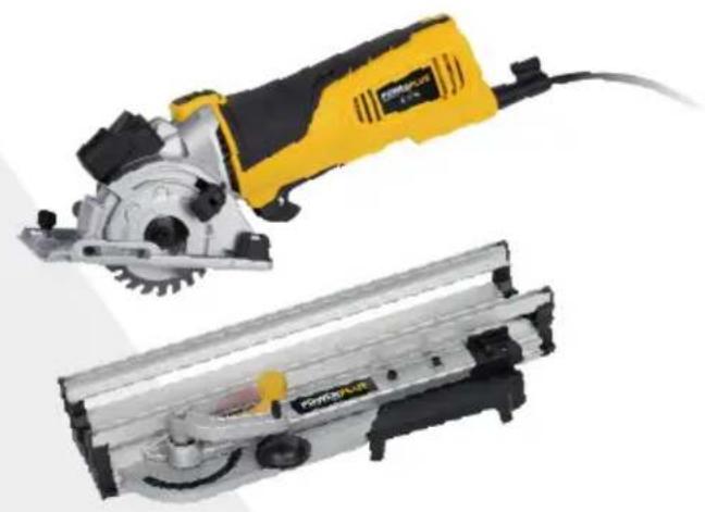
Vario
WWW.VARO.COM
DESIGNED AND MARKETED BY VARO
Copyright by varo
VARO - VIC. VAN ROMPUY nv
JOSEPH VAN INSTRAAT 9 - 2500 LIER - BELGIUM
OFFICES:
IBERICA BRICOLAGE S.L. - ESPANA
ASIA PACIFIC HONG KONG Ltd / SHANGHAI PRC
AUSTRALIA Pty Ltd
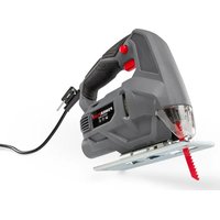


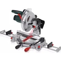

- MINI CIRCULAR SAW 600W + MITRE BASE POWX1365MB
- APPLICATION
- OVERVIEW COMPONENTS: MINI SIRCULAR SAW (FIG A)
- OVERVIEW COMPONENTS: MITRE BASE (FIG. B)
- PACKAGE CONTENT LIST
- POWX1365MB EN
- When parts are missing or damaged, please contact your dealer.
- SYMBOLS
- GENERAL POWER TOOL SAFETY WARNINGS
- Work area
- Electrical safety
- Always check that the power supply corresponds to the voltage on the rating plate.
- Personal safety
- Power tool use and care
- Service
- SPECIFIC SAFETY WARNINGS FOR CIRCULAR SAWS
- ASSEMBLY
- Setting the cutting depth (Fig .1)
- Changing a saw blade
- OPERATION
- Holding and switching ON/OFF
- Switching on the tool:
- Releasing the plunge stop
- Setting the guide fence
- Laser line generator
- Line following
- Dust extraction
- CUTTING
- CUT-OUTS
- CUTTING PARTICULARLY TOUGH OR ABRASIVE MATERIALS
- Sheet metal:
- Ceramic tiles, slates etc:
- Plasterboard:
- MITRE BASE
- Cutting angle adjustment
- Installing and adjusting the clamp
- Adjusting position of work platform with angle scale (22)
- Cutting with workbench
- CLEANING AND MAINTENANCE
- Blades
- TECHNICAL DATA
- NOISE
- WARRANTY
- ENVIRONMENT
- MINI SERRA CIRCULAR 600 W + BASE ANGULAR POWX1365MB
- APLICACAO
- RENGJØRING OG VEDLIKEHOLD
- MINI KYKAIKO IPIONI 600W + BA∑H ΦAANTΣOΓΩNIAZPOWX1365MB
- EΦAPMÖΓ
- PRIMJENA 3
- RAD 7
- MINI KRUŽNA PILA 600 W + DRŽAĆ ZA IZREZIVANJE POD KUTOM POWX1365MB
- PRIMJENA
- OPIS: MINI KRUZNA PILA (SLIKA A)
- OPIS: DRZACA ZA IZREZIVANJE POD KUTOM (SLIKA B)
- MINI KRUZNA TESTERA 600 W SA POSTOLJEM ZA KOSO SEČENJE POWX1365MB
- PRIMENA
- Pridrzeni a prepnutI ON/OFF
- Rezani's pracovnim stolem
- MINIFERÁSTRÁU CIRCULAR 600 W + SUPORT DE TÄIERE IN UNGHI ASCUTIT POWX1365MB
- DOMENII DE UTILIZARE
- LIPKUYJIAPHAR MHHI-PIJIA 600 BT + DEPJKATEJB DJIYCKOCOBPOWX1365MB
- OBJACTb IPIPIMEHEHnA
- O63OP KOMNHOHTOB LIPKUJARPHOIMNHIN-PIJIbI (PNC.A)
- O63OP KOMNOHEHTOB DEPXATEJIЯ DKOCOB (PNC. B)
- CODEPXXUMOE YNAKOBKN
- BHIMAHHE! YnakoBoHbIe MaTePnAbI - 3TO He nrpyuKIn! He no3BOnJaTe DeTAM nRpaTb c PnactNKOBbIMn naKeTaM! EcTb onaChocb ydyWeHna!
- Ecn n deTaN OTCyTCTBYOT Nn NOBpeXdHbI, 6paNTecb K CBOemy dNlepy.
- YCJIOBHBIE OBO3HAUEHNIA
- 3neKmpo6e3onacHocmb
- Bcerda npOBepaIte, cyo6bI HanpJxHne B cetn COOTBeTCTBOBaNo HapJxHIO, yka3aHHOMy Ha Ta6JIuYKe C TexHueeCKIMN daHHbIMN.
- Luyna 6e3oNaChocmb
- POWX1365MB RU
- 3Kcnnyamauua u yxod 3a 3neKmpouHcmpymom
- 06cnykuhaue
- 7OCOBbIE MEPbI INPEIOCTOPOXHOCTNДЯ CINPKUJIAPHBIXПИ
- CBOPKA
- Hacmpouka any6unbl nponuna (Puc. 1)
- CmeHa nulbHOzo ducka
- BkIIOUeHHe INHCTpyMeHTa
- OtnyckaHne orpaHnHTeJI BepTkaJIbHOro nepMeueHn
- YcmaHOeKa HnpaBraHoueu nHaHKU
- Fehepamop naephou nuhuu
- CneoBHe JnHuu
- YdaJIeHue onuJok
- 10ПИЛЕНЕ
- BblPE3bl
- ПИЛЕНЕ TPyДнHOОБРАБATыIBAEMbIX ИПАБР3ИВHBIX MATEРПАЛOB
- JucmoBu Memann:
- Kepamueckue numku, wufephble numku u m.d.
- FuncokapmoH
- DEPSEXIELДЯ CKOCOB
- Pezylupoega ya na pe3ku
- YcmaHOBa u peayIupoKa npuxuma
- TEXHnueCKNE DAHHbIE
- WYM
- TAPAHTNU
- OKPYXAIOUIA CPEDA
- MNHU CINPKUJIPEH TPNOH 600 W + OCHOBA 3APR3AHE IOd bIbJIPOWX1365MB
- ПЕДHA3HAUEHNE HA ELEKTPOHCTPymeHTA
- OПИСАHЕ: МИн LИРКУЛЯPEH TPNOH (ФИГ. A)
- IPERJIeH HA KOMHOHEHTIe HA OCHOBATA 3A PRA3AHE IOD bIbI (ΦNΓ. B)
- CπисьК HA CьДьРЖAHNETO HA ONAKOBKATA
- CUMBOJIH
- BkIIOUbaHe Ha HnHCTpyMeHTa:
- Ocbo6oxdaBaHe Ha cTonepa 3a Bp3BaHe
- Hacmpoubahe Ha eodeuua luhean
- TneHepamop Ha na3epeH Ib4
- CnedeaeHa JnHua
- Ipaoxoynoosumen
- P3AHE
- KOHTYPN HA N3PRA3BAHE
- P83AHE HA OCOBEHO TBbPdN IJI N ABPA3NBH N MATEPNAJN
- Memannu Jucmu:
- KepamuHu nNoCu, nokpuBuHu nNoCu u dp.:
- FuncokapmoH:
- OCHOBA 3A PRA3AHE IOd bIbJI
- Hacmpouka Ha b2bna Ha p3aHe
- HcmaIupaHe u Hacmpouka Ha cko6ama
- P83aHe c pa6omHa maca
- NOUHCTBAHE I IOIDPbJKA
- Duckoee
- TEXHnueCKn DAHHN
- MINI RIPZAGIS 600 W + DEFLEKTORA BAZEPOWX1365MB
- PIELIETOJUMS
- MINIKETASSAAG 600 W + KALLUTUSALUS POWX1365MB
- OTSTARVE
- ÜLDISED HOIATUSED JA OHUTUSJUHISED
Brand : PowerPlus
Model : POWX1365MB
Category : Saw