Beovision 12 - Television BANG & OLUFSEN - Free user manual and instructions
Find the device manual for free Beovision 12 BANG & OLUFSEN in PDF.



| Product type | Plasma television |
| Brand | Bang & Olufsen |
| Model | Beovision 12 |
| Dimensions (W x H x D) | 1610 x 801 mm (depth not specified) |
| Weight | Not specified |
| Power supply | Mains, special cable provided |
| Power consumption | Not specified |
| Screen | Plasma |
| Main functions | Automatic colour management (detection arm), 3D compatibility, integrated centre speaker, wall mount |
| Connections | HDMI IN, POWER LINK, CONTROL, R OUT, DISPLAY 1, CENTRE 1, MONITOR, IR IN, BEOSYSTEM |
| Standby indicator | Red (off) / Green (BeoSystem on without picture) |
| Operating temperature | 10 °C to 40 °C |
| Maximum altitude | Approximately 1,500 m (minimum atmospheric pressure 833 hPa) |
| Screen maintenance | Soft, dry cloth, no liquid or aerosol products |
| Surface maintenance | Soft cloth slightly moistened with water and mild detergent |
| Safety | Do not expose to rain or moisture, do not place liquid objects, do not disassemble |
| Spare parts | Available from Bang & Olufsen dealer |
| Repairability | Refer to qualified Bang & Olufsen personnel |
| Warranty | Not specified |
Frequently Asked Questions - Beovision 12 BANG & OLUFSEN
User questions about Beovision 12 BANG & OLUFSEN
0 question about this device. Answer the ones you know or ask your own.
Ask a new question about this device
Download the instructions for your Television in PDF format for free! Find your manual Beovision 12 - BANG & OLUFSEN and take your electronic device back in hand. On this page are published all the documents necessary for the use of your device. Beovision 12 by BANG & OLUFSEN.
USER MANUAL Beovision 12 BANG & OLUFSEN
Cautions, 4
Traditional Chinese, 56
English, 8
Simplified Chinese, 60
Danish, 12
Korean, 64
German, 16
Japanese, 68
Spanish, 20
Arabic, 72
French, 24
Czech, 76
Italian, 28
Hungarian, 80
Latvian, 84
Swedish, 44
Slovakian, 96
Russian, 52
Important information, 104
Cautions
English
- Place your television on a firm, stable surface.
- The TV is not designed to stand on its own. It must be supported until mounted on a wall bracket. To prevent injury, use Bang & Olufsen approved wall brackets only!
- Ensure that the television is positioned, set up and connected in accordance with the instructions in this Guide.
- Do not subject the television to rain, high humidity or sources of heat.
- Do not strike the glass with hard or pointed items.
- The product can only be switched off completely by disconnecting it from the wall socket. The disconnect device shall remain readily operable.
- Do not expose this equipment to dripping or splashing and ensure that no objects filled with liquids, such as vases are placed on the equipment.
- No naked flame sources, such as lighted candles should be placed on the equipment.
- If the product is equipped with a grounded mains lead and 3-pin plug, the product shall be connected to a mains socket wall outlet with a protective earth connection. The ground pin of the mains plug must not be removed, due to the danger of electric shock. If a wall outlet with protective earth is not available, an electrician should be contacted.
WARNING: To reduce the risk of fire or electric shock, do not expose this appliance to rain or moisture.

The lightning flash with arrowhead symbol within an equilateral triangle is intended to alert the user to the presence of uninsulated "dangerous
voltage" within the product's enclosure that may be of sufficient magnitude to constitute a risk of electric shock to persons.

The exclamation point within an equilateral triangle is intended to alert the user to the presence of important operating and maintenance (servicing) instructions
in the literature accompanying the product.
Read these instructions.
Keep these instructions.
Heed all warnings.
Follow all instructions.
Do not use this apparatus near water.
Clean only with dry cloth.
Do not block any ventilation openings. Install in accordance with the manufacturer's instructions.
Do not install near any heat sources such as radiators, heat registers, stoves, or other apparatus (including amplifiers) that produce heat.
Do not defeat the safety purpose of the polarized or grounding-type plug. A polarized plug has two blades with one wider than the other. A grounding type plug has two blades and a third grounding prong. The wide blade or the third prong are provided for your safety. If the provided plug does not fit into your outlet, consult an electrician for replacement of the obsolete outlet.
Protect the power cord from being walked on or pinched particularly at plugs, convenience receptacles, and the point where they exit from the apparatus.
Only use attachments/accessories specified by the manufacturer.
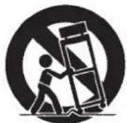
Use only with the cart, stand, tripod, bracket, or table specified by the manufacturer, or sold with the apparatus. When a cart is used, use caution when moving the cart/apparatus combination to avoid injury from tip-over.
Unplug this apparatus during lightning storms or when unused for long periods of time. Refer all servicing to qualified service personnel. Servicing is required when the apparatus has been damaged in any way, such as power-supply cord or plug is damaged, liquid has been spilled or objects have fallen into the apparatus, the apparatus has been exposed to rain or moisture, does not operate normally, or has been dropped.
Danish
Traditional Chinese
Place the television on a firm and stable surface.
Simplified Chinese
Hungarian
Slovakian
Slovenian
Set up your television
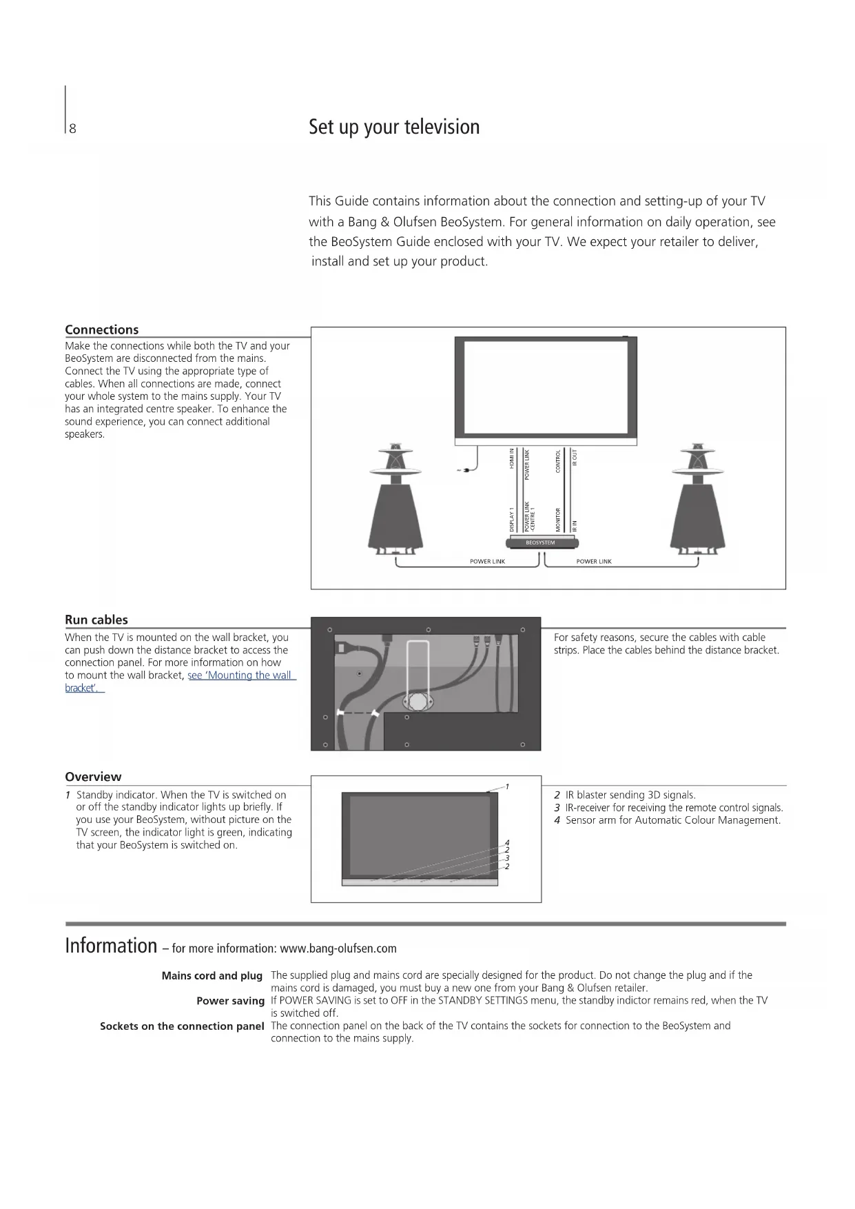
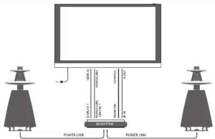
This Guide contains information about the connection and setting-up of your TV with a Bang & Olufsen BeoSystem. For general information on daily operation, see the BeoSystem Guide enclosed with your TV. We expect your retailer to deliver, install and set up your product.
Connections
Make the connections while both the TV and your BeoSystem are disconnected from the mains. Connect the TV using the appropriate type of cables. When all connections are made, connect your whole system to the mains supply. Your TV has an integrated centre speaker. To enhance the sound experience, you can connect additional speakers.
Run cables
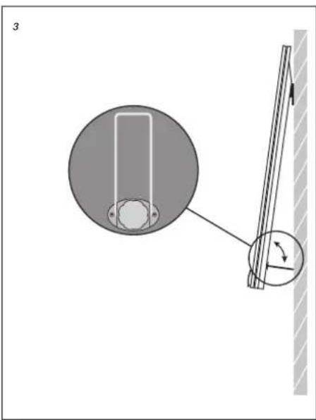
When the TV is mounted on the wall bracket, you can push down the distance bracket to access the connection panel. For more information on how to mount the wall bracket, see 'Mounting the wall bracket'.

For safety reasons, secure the cables with cable strips. Place the cables behind the distance bracket.
Overview
1 Standby indicator. When the TV is switched on or off, the standby indicator lights up briefly. If you use your BeoSystem without a picture on the TV screen, the indicator light is green, indicating that your BeoSystem is switched on.
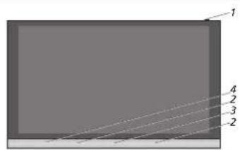
2 IR blaster sending 3D signals. 3 IR receiver for receiving the remote control signals. 4 Sensor arm for Automatic Colour Management.
Information – for more information: www.bang-olufsen.com
Mains cord and plug. The supplied plug and mains cord are specially designed for the product. Do not change the plug, and if the mains cord is damaged, you must buy a new one from your Bang & Olufsen retailer.
Power saving. If POWER SAVING is set to OFF in the STANDBY SETTINGS menu, the standby indicator remains red when the TV is switched off.
Sockets on the connection panel. The connection panel on the back of the TV contains the sockets for connection to the BeoSystem and connection to the mains supply.
Maintenance
Regular maintenance, such as cleaning, is the responsibility of the user. To achieve the best result, follow the instructions below. The Automatic Colour Management automatically compensates for colour changes on the screen approximately every 100 hours of use.
Automatic Colour Management
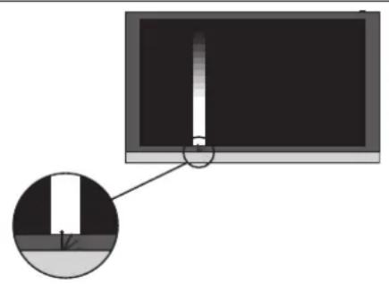
Automatic Colour Management ensures perfect colours on the screen continuously. During calibration, a sensor arm swings up from the TV frame and an on-screen bar changes between various greyscale colours.
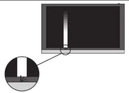
The calibration can be manual or automatic. We recommend that you let the TV perform the calibration automatically instead of manually. Do not switch off the TV or disconnect it from the mains during the calibration. For more information, see the BeoSystem Guide enclosed with your TV.
Cleaning instructions
Cabinet surfaces
Wipe dust off the surfaces using a dry, soft cloth. To remove stains or dirt, use a soft, lint-free, firmly wrung cloth, and a solution of water and mild detergent, such as washing-up liquid. Never use alcohol or other solvents to clean any parts of the TV.
Plasma screen
Use a soft, dry cloth to wipe dust off the screen. Do not use liquid cleaners or aerosol cleaners. Avoid spraying liquid directly on the screen as this may damage the speakers or other parts. Some micro-fibre cloths may harm the optical coating due to their strong abrasive effect.
Cautions
- The TV is intended for indoor use in dry, domestic environments only, and for use within a temperature range of 10–40°C (50–105°F).
- If the TV has been exposed to temperatures below 5°C (40°F), leave it at room temperature and wait until the TV has regained normal room temperature before it is connected to the mains and switched on.
- The picture can be distorted at altitudes where the air pressure is lower than 833 hPa (approximately 1500 m (5000 feet) or higher.
- Do not place any items on top of the TV.
- Do not attempt to open the TV. Leave such operations to qualified service personnel!
- Avoid placing the TV in direct sunlight or direct artificial light, such as a spotlight.
- Do not connect any of the products in your system to the mains, until you have connected all the cables.
- Do not leave the TV in contact with articles containing rubber or PVC for long periods of time.
- Do not allow still pictures to be displayed on the screen for an extended period of time, as this can cause a permanent after-image to remain on the screen.
Mounting the wall bracket
The wall bracket must be mounted by qualified Bang & Olufsen personnel. Follow the guidelines for mounting the TV on the wall bracket on this and the following page.
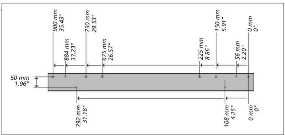
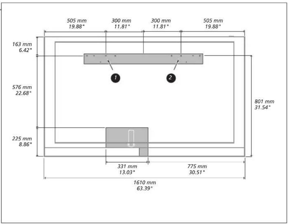
Wall bracket and TV dimensions
Use the correct size and type of screws and wall anchors – taking into account the construction and condition of the wall. Use six round-headed screws and wall anchors, three in each side – each screw with a minimum load rating of 30 kg (66 lbs).
Ventilation
To ensure proper ventilation, allow at least 10 cm (4") of space at the top, bottom and sides. Do not cover the ventilation holes on the rear, as this may cause the TV to overheat.
Information
Special notice about light partition walls
If you intend to hang the BeoVision on a gypsum wall (also known as drywall or wallboard), the wall bracket must be fastened to a vertical stud. Use six round-headed screws (ø 6 mm, 0.24"), three in each side of the wall bracket. Two screws must penetrate the gypsum and be screwed a minimum of 65 mm (2.5") into a vertical stud.
Mount the wall bracket
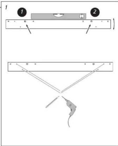
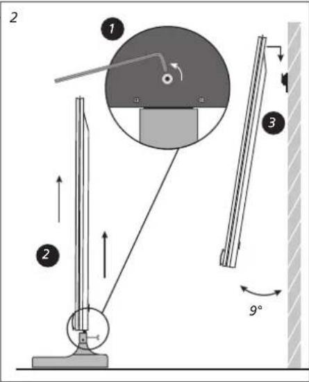
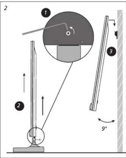
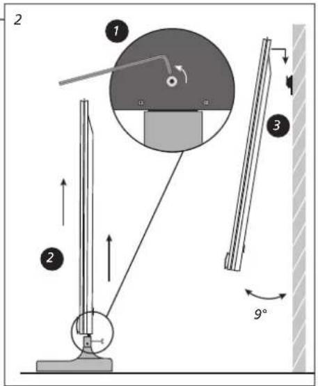
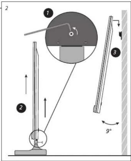
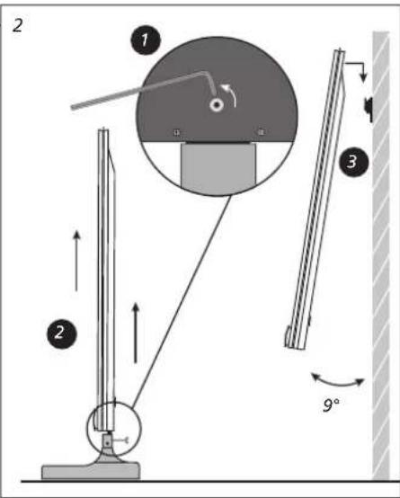
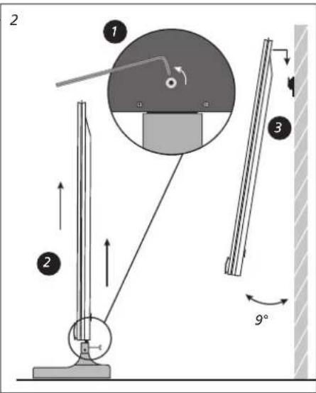
We recommend that you leave the TV on the service feet while you mount the wall bracket. When lifting the TV, grip the top and bottom, at least 10 cm (4") from each bottom edge. Remember to carry the TV in such a way that it is in an upright position at all times.
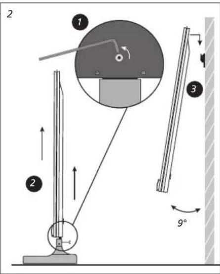
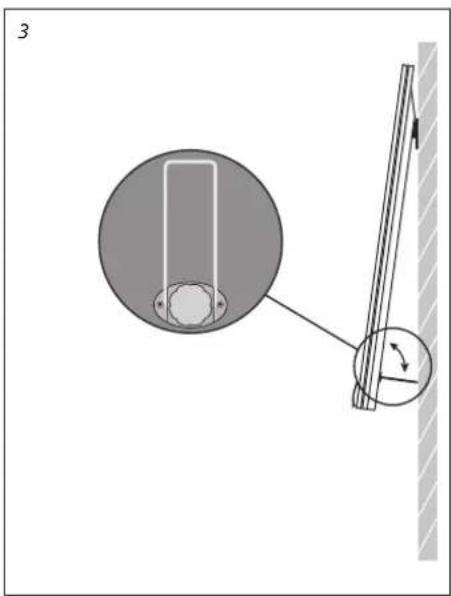
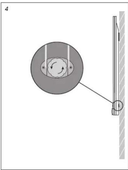
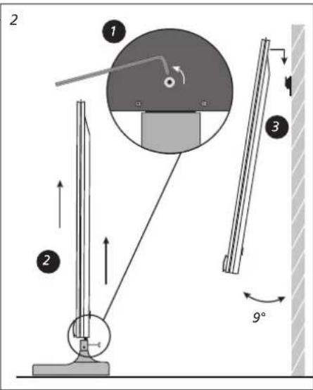
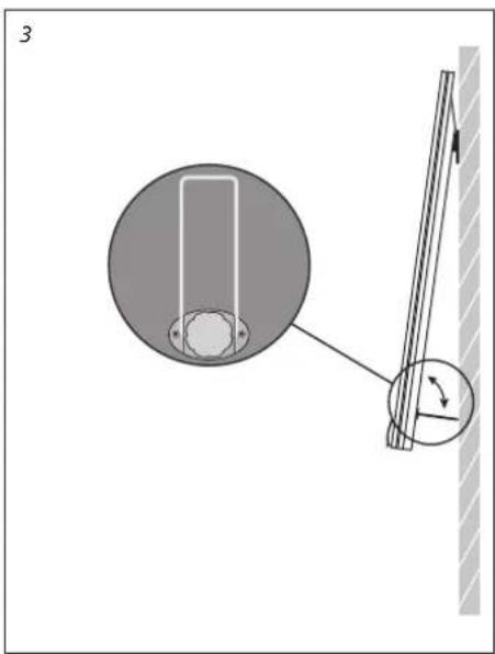
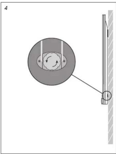
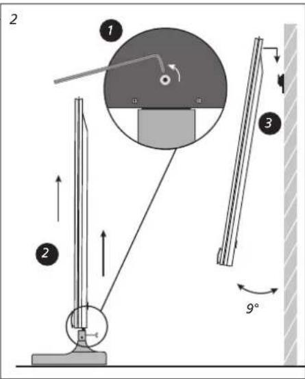
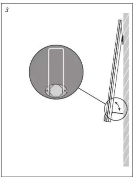
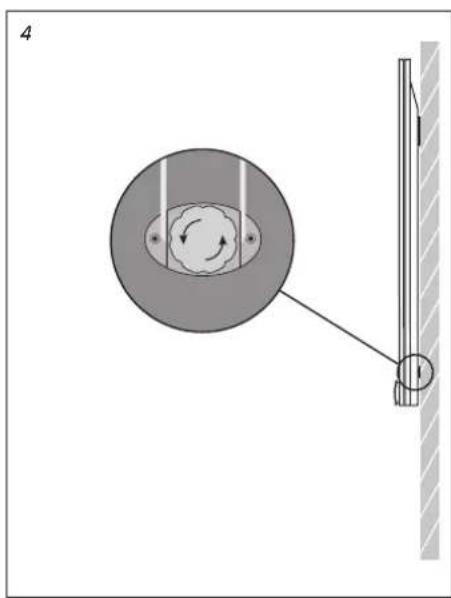
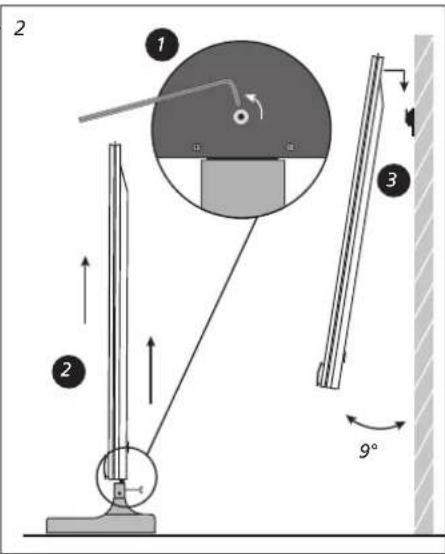
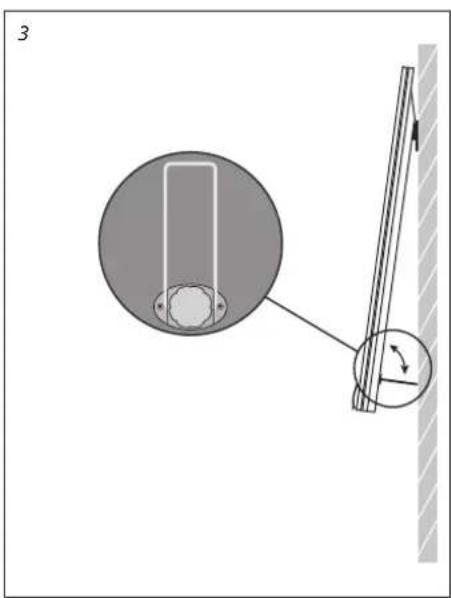
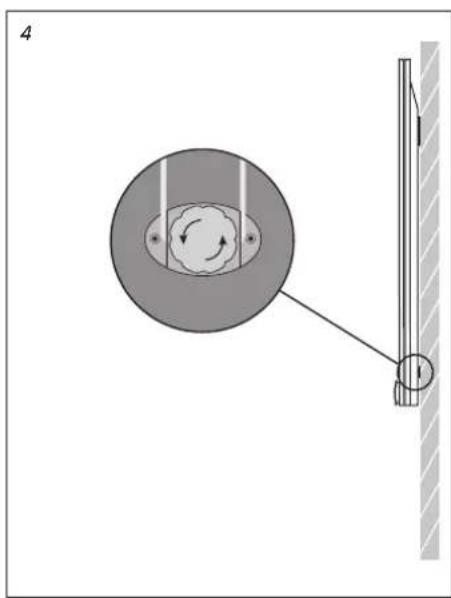
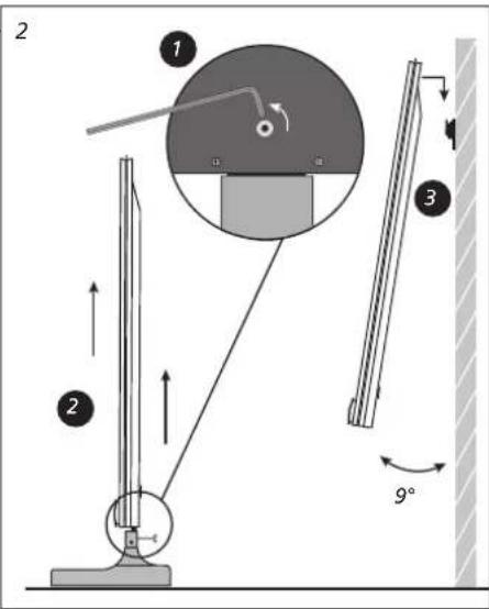
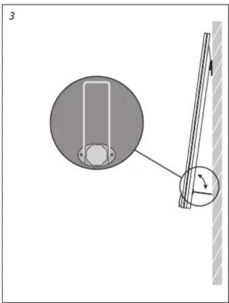
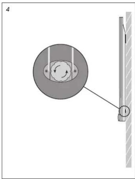
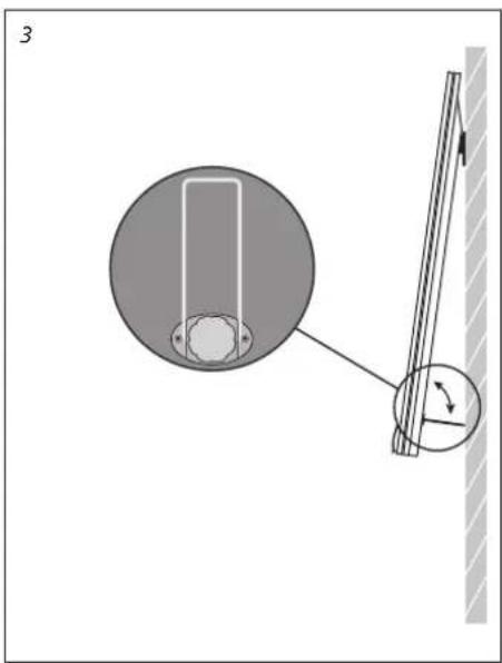
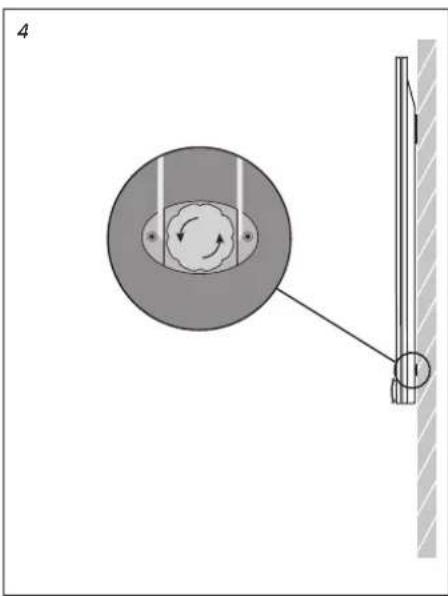
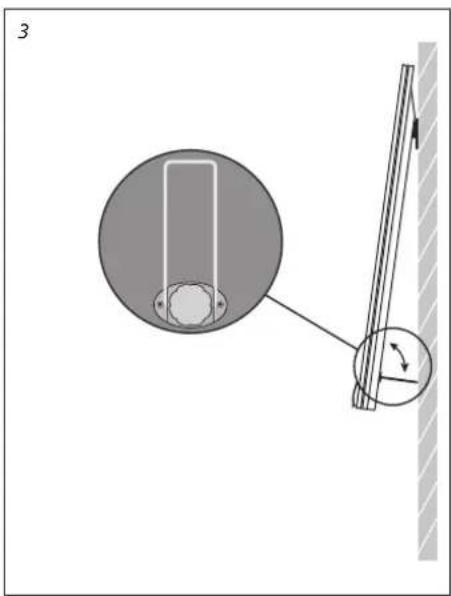
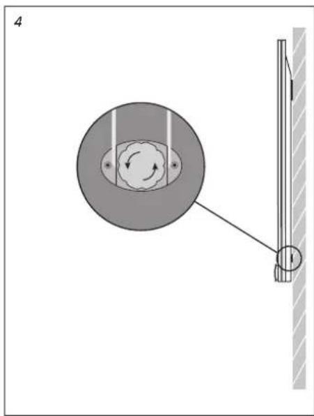
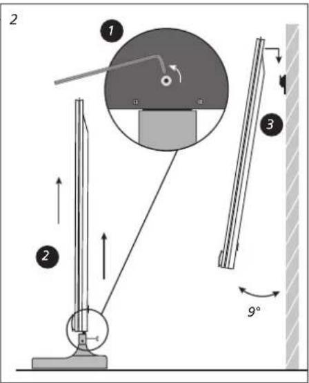
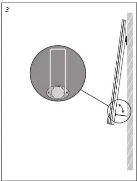
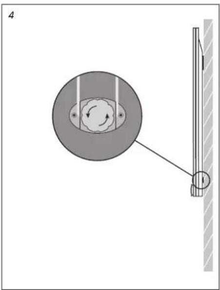
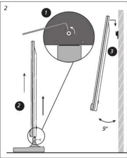
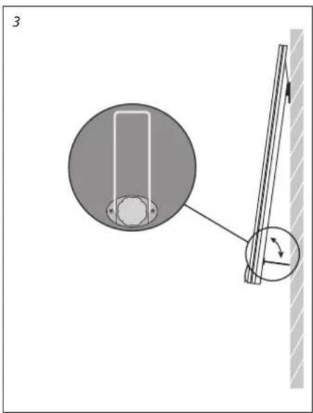
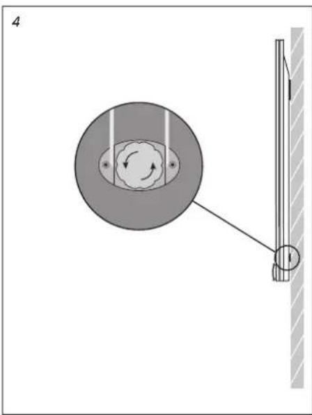
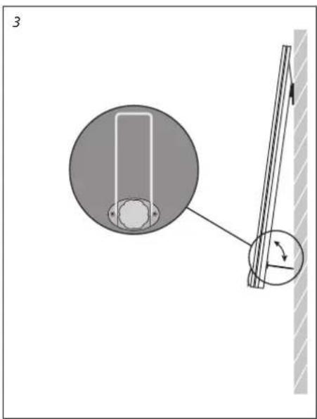
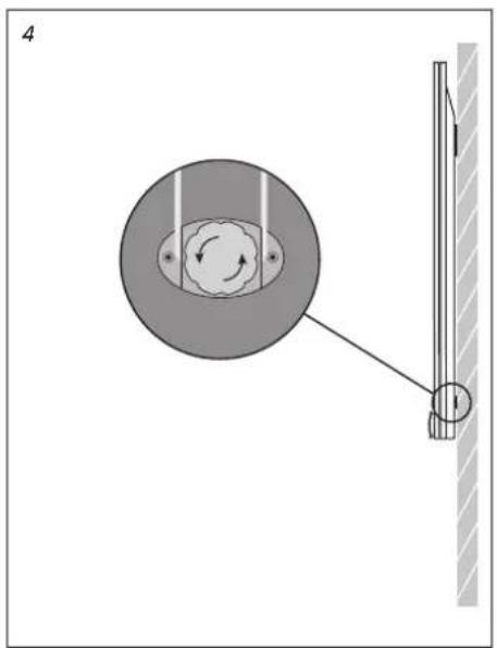
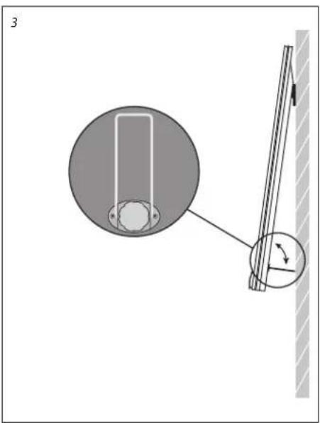
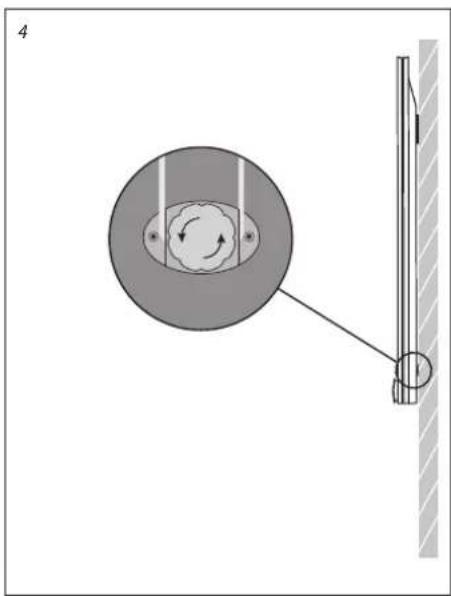
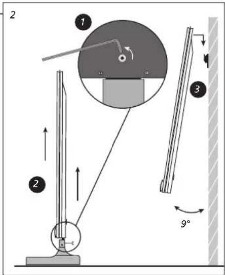
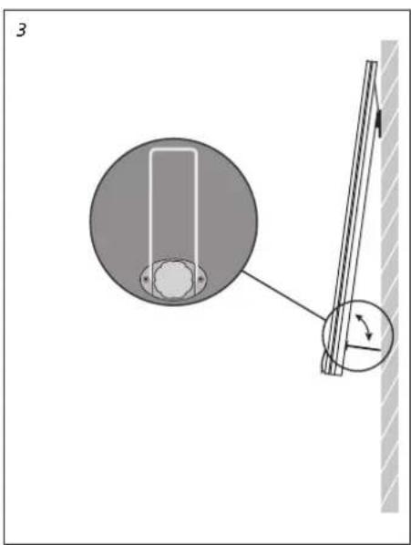
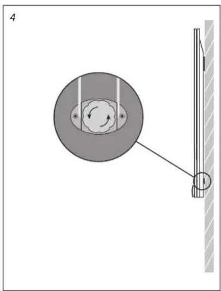
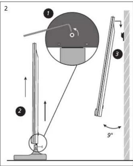
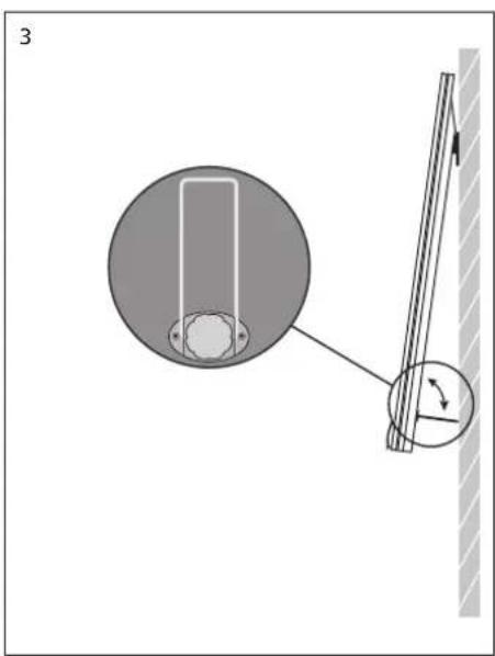
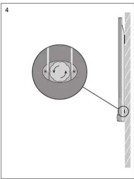
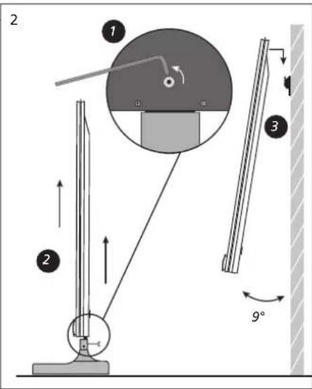
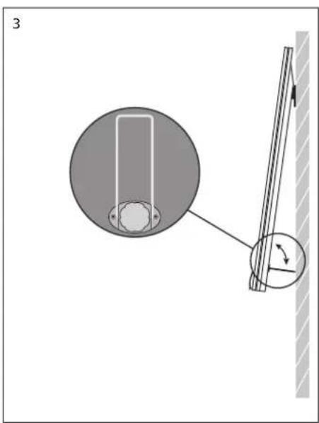
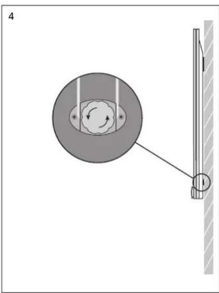
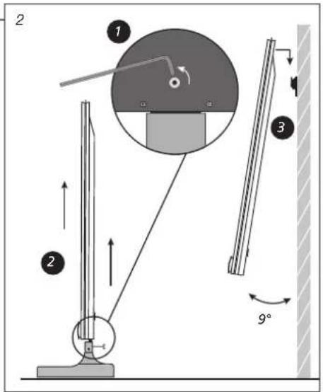
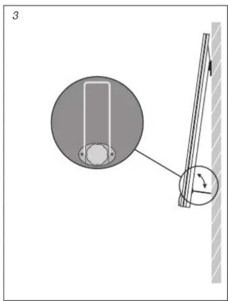
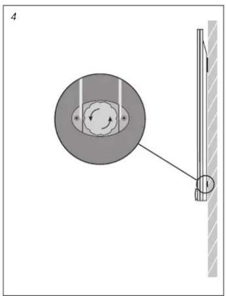
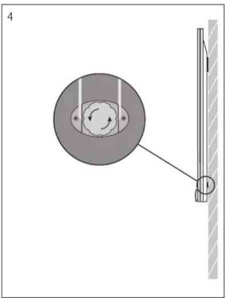
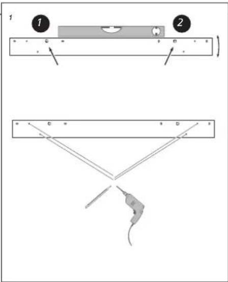
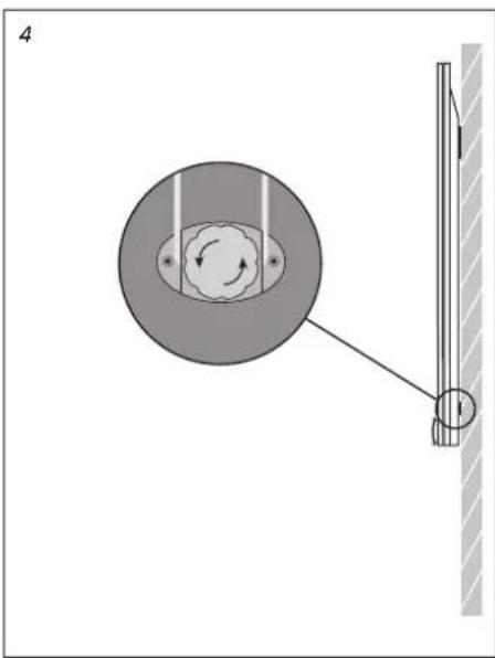
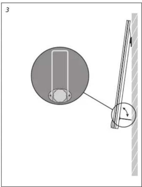
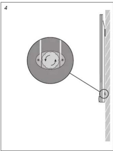
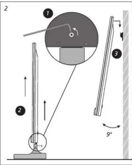
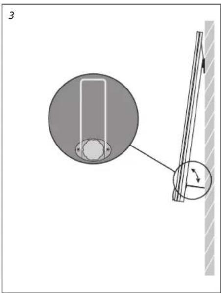
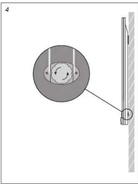
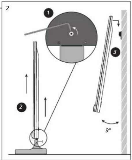
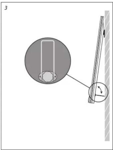
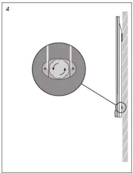
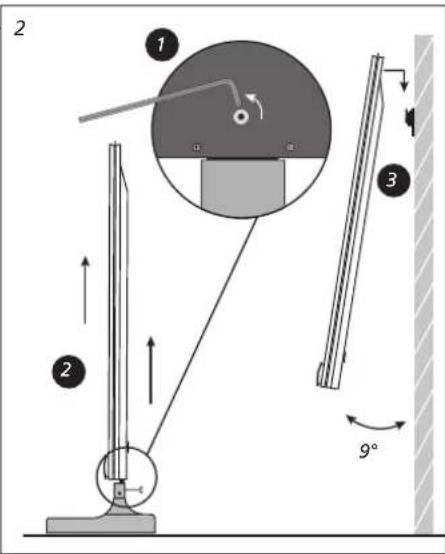
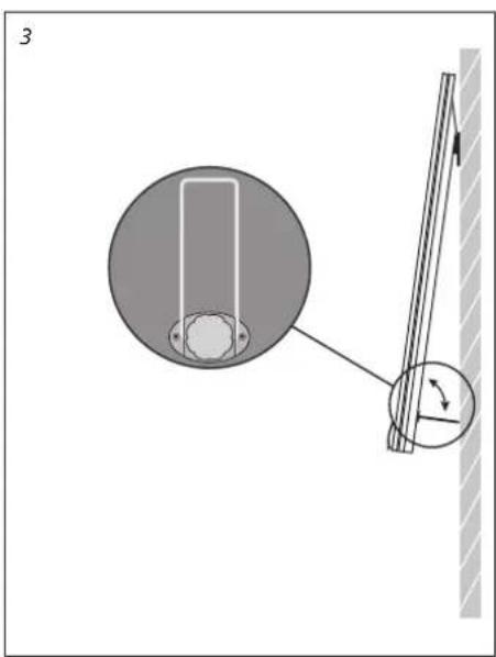
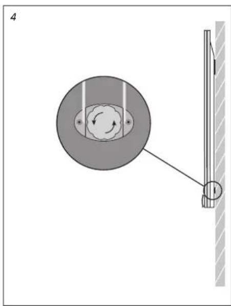
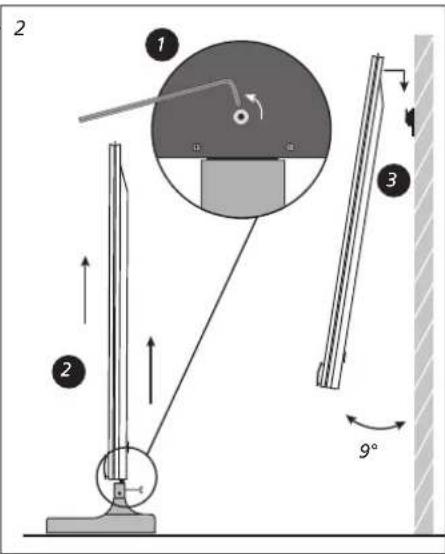
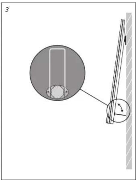
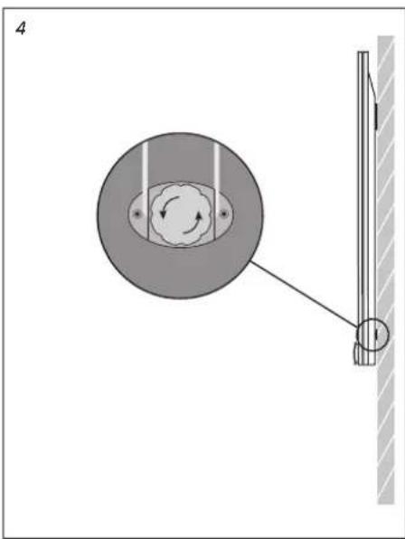
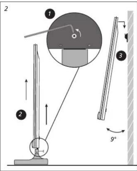
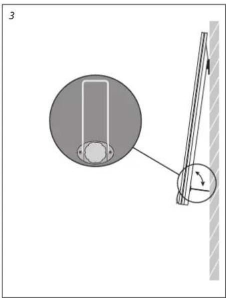
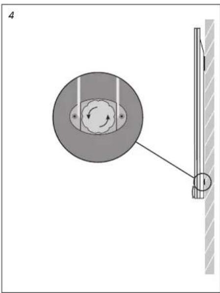
1 Mount one screw (1) to keep the wall bracket in place. Mount one more screw (2) and ensure that the bracket is level. Use the wall bracket to mark the placement of the other holes to be drilled and mount the wall bracket. 2 Remove the screw to detach the service feet (1). Lift the TV off the service feet (2), then mount it on the wall bracket (3). To mount the TV, you must hold it in an angle of 9°. 3 If you connect the TV to your BeoSystem, while the TV is mounted on the wall bracket, push down the distance bracket, to access the connection panel. When you have made the connections, push the distance bracket into place again. 4 Use the screw to adjust the position of the TV.
Handling
Dismount the TV from the wall bracket
Due to the heavy weight of the TV, any moving or lifting of the TV should be performed by qualified personnel – using the proper equipment.
Before you lift off the TV, push down the distance bracket, and attach the enclosed service feet. To lift the TV off the wall bracket, you must pull out the TV at the bottom to make an angle of 9°, then lift it off.
Set up the TV
Automatic Colour Management
Handling
Automatic Colour Management
Handling
Automatic Colour Management
Handling
Automatic Colour Management
Wall mount installation
Wall mount installation
Handling
Automatic Colour Management
Handling
Automatic Colour Management
Handling
Remove the TV from the wall mount
Automatic Colour Management
Handling
Remove the TV from the wall mount
Automatic Colour Management
Handling
Automatic Colour Management
Automatic Colour Management
Handling
Handling
Auto Colour Management
Automatic Colour Management
TV settings
Automatic Colour Management
TV setup
Automatic Colour Management
Writing stand
Automatic Colour Management
Wall mount installation

Handling
Automatic Colour Management
Operation
Auto Colour Management
Moving
Removing the TV from the wall mount
Automatic Colour Management
Automatic Colour Management
Automatic Colour Management
Automatic Colour Management ensures consistently perfect color reproduction on the screen. During calibration, the sensor arm extends from the television frame and the band on the screen will change color in various shades of gray.
Operation
Automatic Colour Management
Operation
Remove the television from the wall bracket
English Waste Electrical and Electronic Equipment (WEEE) – Environmental protection
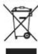
Electrical and electronic equipment, parts and batteries marked with this symbol must not be disposed of with normal household waste; all electrical and electronic equipment, parts and batteries must be collected and disposed of separately.
When disposing of electrical and electronic equipment and batteries by use of the collection systems available in your country, you protect the environment, human health and contribute to the prudent and rational use of natural resources. Collecting electrical and electronic equipment, batteries and waste prevents the potential contamination of nature with the hazardous substances which may be present in electrical and electronic products and equipment. Your Bang & Olufsen retailer will advise you of the correct way of disposal in your country.
If a product is too small to be marked with the symbol, it will appear in the User Guide, on the Guarantee certificate, or on the packaging.
All Bang & Olufsen products comply with applicable environmental legislation throughout the world.

This product is in conformity with the provisions of the Directives 2009/125/EC, 2004/108/EC and 2006/95/EC.
For the US-market only!
Changes or modifications not expressly approved by the party responsible for compliance could void the user's authority to operate the equipment.
NOTE: This equipment has been tested and found to comply with the limits for a class B digital device, pursuant to part 15 of the FCC Rules. These limits are designed to provide reasonable protection against harmful interference in a residential installation. This equipment generates, uses and can radiate radio frequency energy and, if not installed and used in accordance with the instructions, may cause harmful interference to radio communications. However, there is no guarantee that interference will not occur in a particular installation. If this equipment does cause harmful interference to radio or television reception, which can be determined by turning the equipment off and on, the user is encouraged to try to correct the interference by one or more of the following measures:
– Reorient or relocate the receiving antenna. – Increase the separation between the equipment and receiver. - Connect the equipment into an outlet on a circuit different from that to which the receiver is connected. - Consult the retailer or an experienced radio/TV technician for help.
This device complies with part 15 of the FCC Rules. Operation is subject to the following two conditions: (1) This device may not cause harmful interference, and (2) this device must accept any interference received, including interference that may cause undesired operation.
For the Canadian market only!
This class B digital apparatus complies with Canadian ICES-003.
Danish
Traditional Chinese
Slovakian
Simplified Chinese
Measures for the Control of Pollution Caused by Electronic Information Products

- CAUTIONS
- ENGLISH
- DANISH
- TRADITIONAL CHINESE
- SIMPLIFIED CHINESE
- HUNGARIAN
- SLOVAKIAN
- SLOVENIAN
- SET UP YOUR TELEVISION
- CONNECTIONS
- RUN CABLES
- OVERVIEW
- MAINTENANCE
- AUTOMATIC COLOUR MANAGEMENT
- CLEANING INSTRUCTIONS
- CABINET SURFACES
- PLASMA SCREEN
- MOUNTING THE WALL BRACKET
- WALL BRACKET AND TV DIMENSIONS
- VENTILATION
- INFORMATION
- MOUNT THE WALL BRACKET
- HANDLING
- SET UP THE TV
- WALL MOUNT INSTALLATION
- AUTO COLOUR MANAGEMENT
- TV SETTINGS
- TV SETUP
- WRITING STAND
- MOVING
- REMOVING THE TV FROM THE WALL MOUNT
- OPERATION
- FOR THE US-MARKET ONLY
- FOR THE CANADIAN MARKET ONLY
Brand : BANG & OLUFSEN
Model : Beovision 12
Category : Television