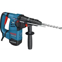
GBH 328 DFR - Drill BOSCH - Free user manual and instructions
Find the device manual for free GBH 328 DFR BOSCH in PDF.


| Product type | Rotary hammer (hammer drill) |
| Brand | Bosch |
| Model | GBH 3-28 DFR (GBH 328 DFR) |
| Rated power input | 800 W |
| Impact rate | 0 - 4000 min⁻¹ |
| Single impact power (EPTA 05/2009) | 3.2 J |
| No-load speed | 0 - 900 rpm |
| Tool holder | SDS-plus |
| Interchangeable chuck | Quick-release chuck and SDS-plus chuck (included) |
| Max. drilling diameter (concrete) | 28 mm |
| Max. drilling diameter (steel) | 13 mm |
| Max. drilling diameter (wood) | 30 mm |
| Weight (according to EPTA 01:2014) | 3.6 kg |
| Protection class | II (double insulation) |
| Sound pressure level | 91 dB(A) |
| Sound intensity level | 102 dB(A) |
| Vibrations (concrete drilling) | 13 m/s² (uncertainty K=2 m/s²) |
| Functions | Hammer drilling, drilling without impact, chiseling, Vario-Lock (36 chisel positions) |
| Rotation direction | Right / left |
| Speed adjustment | Electronic progressive (by trigger pressure) |
| Rotation / impact stop | Yes |
| Additional handle | Yes, adjustable (insulated gripping surface) |
| Depth stop | Yes, adjustable |
| Dust protection cap | Yes, on the tool holder |
| Maintenance | Clean the ventilation slots, replace the dust protection cap if damaged, clean the tool holder after each use |
Frequently Asked Questions - GBH 328 DFR BOSCH
User questions about GBH 328 DFR BOSCH
0 question about this device. Answer the ones you know or ask your own.
Ask a new question about this device
Download the instructions for your Drill in PDF format for free! Find your manual GBH 328 DFR - BOSCH and take your electronic device back in hand. On this page are published all the documents necessary for the use of your device. GBH 328 DFR by BOSCH.
USER MANUAL GBH 328 DFR BOSCH
ORJ BUCH-770-008.book Page | Wednesday, June 15, 2016 2:12 PM
natural_image
Illustration of a Bosch DRLR drill press with handle and screwdriver (no text or symbols)Robert Bosch Power Tools GmbH
70538 Stuttgart
GERMANY
www.bosch-pt.com
1609 92A 2A9 (2016.06) PS/229

GBH Professional
3-28 DRE|3-28DFR

BOSCH
to instruction originate
natural_image
Mechanical illustration of a drill bit being inserted into a drill bit, showing tool path and motion direction (no text or symbols)5
natural_image
Mechanical illustration of a drill bit with a 5-pin drill bit, showing tool path and motion direction (no text or symbols)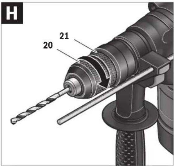
text_image
H 20 21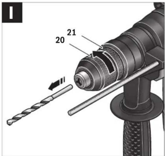
text_image
20 21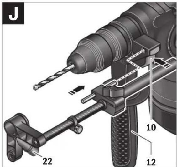
text_image
J 22 10 12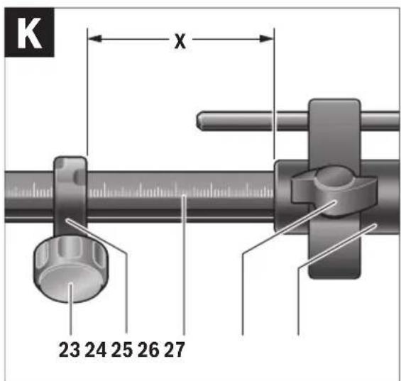
text_image
K x 23 24 25 26 27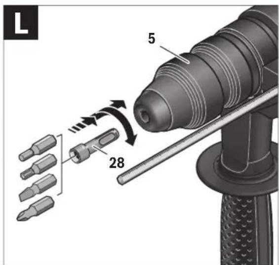
text_image
L 5 28


6 | Deutsch
Deutsch
Sicherheitshinweise
General Power Tool Safety Warnings
WARNING Read all safety warnings and all instructions. Failure to follow the warnings and
instructions may result in electric shock, fire and/or serious injury.
Save all warnings and instructions for future reference.
The term "power tool" in the warnings refers to your mains-operated (corded) power tool or battery-operated (cordless) power tool.
Work area safety
- Keep work area clean and well lit. Cluttered or dark areas invite accidents.
▶ Do not operate power tools in explosive atmospheres, such as in the presence of flammable liquids, gases or dust. Power tools create sparks which may ignite the dust or fumes.
▶ Keep children and bystanders away while operating a power tool. Distractions can cause you to lose control.
Electrical safety
▶ Power tool plugs must match the outlet. Never modify the plug in any way. Do not use any adapter plugs with earthed (grounded) power tools. Unmodified plugs and matching outlets will reduce risk of electric shock.
▶ Avoid body contact with earthed or grounded surfaces, such as pipes, radiators, ranges and refrigerators. There is an increased risk of electric shock if your body is earthed or grounded.
▶ Do not expose power tools to rain or wet conditions.
Water entering a power tool will increase the risk of electric shock.
▶ Do not abuse the cord. Never use the cord for carrying, pulling or unplugging the power tool. Keep cord away from heat, oil, sharp edges and moving parts. Damaged or entangled cords increase the risk of electric shock.
When operating a power tool outdoors, use an extension cord suitable for outdoor use. Use of a cord suitable for outdoor use reduces the risk of electric shock.
▶ If operating a power tool in a damp location is unavoidable, use a residual current device (RCD) protected supply. Use of an RCD reduces the risk of electric shock.
Personal safety
Stay alert, watch what you are doing and use common sense when operating a power tool. Do not use a power tool while you are tired or under the influence of drugs, alcohol or medication. A moment of inattention while operating power tools may result in serious personal injury.
▶ Use personal protective equipment. Always wear eye protection. Protective equipment such as dust mask, non-skid safety shoes, hard hat, or hearing protection used for appropriate conditions will reduce personal injuries.
▶ Prevent unintentional starting. Ensure the switch is in the off-position before connecting to power source and/or battery pack, picking up or carrying the tool.
Carrying power tools with your finger on the switch or energising power tools that have the switch on invites accidents.
Remove any adjusting key or wrench before turning the power tool on. A wrench or a key left attached to a rotating part of the power tool may result in personal injury.
▶ Do not overreach. Keep proper footing and balance at all times. This enables better control of the power tool in unexpected situations.
▶ Dress properly. Do not wear loose clothing or jewellery. Keep your hair, clothing and gloves away from moving parts. Loose clothes, jewellery or long hair can be caught in moving parts.
▶ If devices are provided for the connection of dust extraction and collection facilities, ensure these are connected and properly used. Use of dust collection can reduce dust-related hazards.
Power tool use and care
Do not force the power tool. Use the correct power tool for your application. The correct power tool will do the job better and safer at the rate for which it was designed.
▶ Do not use the power tool if the switch does not turn it on and off. Any power tool that cannot be controlled with the switch is dangerous and must be repaired.
▶ Disconnect the plug from the power source and/or the battery pack from the power tool before making any adjustments, changing accessories, or storing power tools. Such preventive safety measures reduce the risk of starting the power tool accidentally.
▶ Store idle power tools out of the reach of children and do not allow persons unfamiliar with the power tool or these instructions to operate the power tool. Power tools are dangerous in the hands of untrained users.
- Maintain power tools. Check for misalignment or binding of moving parts, breakage of parts and any other condition that may affect the power tool's operation. If
14 | English
damaged, have the power tool repaired before use. Many accidents are caused by poorly maintained power tools.
- Keep cutting tools sharp and clean. Properly maintained cutting tools with sharp cutting edges are less likely to bind and are easier to control.
▶ Use the power tool, accessories and tool bits etc. in accordance with these instructions, taking into account the working conditions and the work to be performed. Use of the power tool for operations different from those intended could result in a hazardous situation.
Service
▶ Have your power tool serviced by a qualified repair person using only identical replacement parts. This will ensure that the safety of the power tool is maintained.
Hammer Safety Warnings
▶ Wear ear protectors. Exposure to noise can cause hearing loss.
▶ Use auxiliary handle(s), if supplied with the tool. Loss of control can cause personal injury.
▶ Hold the tool by the insulated gripping surfaces when performing operations where the application tool or the screw could contact hidden wiring or its own power cord. Contact with a "live" wire will also make exposed metal parts of the power tool "live" and shock the operator.
▶ Use suitable detectors to determine if utility lines are hidden in the work area or call the local utility company for assistance. Contact with electric lines can lead to fire and electric shock. Damaging a gas line can lead to explosion. Penetrating a water line causes property damage or may cause an electric shock.
When working with the machine, always hold it firmly with both hands and provide for a secure stance. The power tool is guided more secure with both hands.
▶ Secure the workpiece. A workpiece clamped with clamping devices or in a vice is held more secure than by hand.
▶ Always wait until the machine has come to a complete stop before placing it down. The tool insert can jam and lead to loss of control over the power tool.
▶ Products sold in GB only: Your product is fitted with a BS 1363/A approved electric plug with internal fuse (ASTA approved to BS 1362). If the plug is not suitable for your socket outlets, it should be cut off and an appropriate plug fitted in its place by an authorised customer service agent. The replacement plug should have the same fuse rating as the original plug. The severed plug must be disposed of to avoid a possible shock hazard and should never be inserted into a mains socket elsewhere.
Products sold in AUS and NZ only: Use a residual current device (RCD) with a rated residual current of 30 mA or less.
Product Description and Specifications

Read all safety warnings and all instructions. Failure to follow the warnings and instructions may result in electric shock, fire and/or serious injury.
While reading the operating instructions, un-
fold the graphics page for the machine and leave it open.
Intended Use
The machine is intended for hammer drilling in concrete, brick and stone, as well as for light chiselling work. It is also suitable for drilling without impact in wood, metal, ceramic and plastic. Machines with electronic control and right/left rotation are also suitable for screwdriving.
Product Features
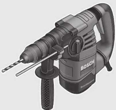
The numbering of the product features refers to the illustration of the machine on the graphics page.
1 Quick change keyless chuck (GBH 3-28 DFR)
2 SDS-plus quick change chuck (GBH 3-28 DFR)
3 SDS-plus tool holder
4 Dust protection cap
5 Locking sleeve
6 Lock ring for rapid-change chuck (GBH 3-28 DFR)
7 On/Off switch
8 Release button for mode selector switch
9 Mode selector switch
10 Button for depth stop adjustment
11 Depth stop
12 Auxiliary handle (insulated gripping surface)
13 Rotational direction switch
14 Handle (insulated gripping surface)
15 Securing screw for key type drill chuck*
16 Key type drill chuck*
17 SDS-plus adapter shank for drill chuck*
18 Drill chuck mounting (GBH 3-28 DFR)
19 Identification grooves
20 Front sleeve of the quick change keyless chuck (GBH 3-28 DFR)
21 Retaining ring of the quick change keyless chuck (GBH 3-28 DFR)
22 Extraction sleeve of the dust extraction attachment*
23 Clamping screw for the dust extraction attachment*
24 Depth stop of the dust extraction attachment*
25 Telescopic pipe of the dust extraction attachment*
26 Wing bolt of the dust extraction attachment*
27 Guide pipe of the dust extraction attachment*
28 Universal bit holder with SDS-plus shank*
*Accessories shown or described are not part of the standard delivery scope of the product. A complete overview of accessories can be found in our accessories program.
English | 15
Technical Data
| Rotary Hammer | GBH 3-28 DRE | GBH 3-28 DFR | |
| Article number | 3611 B3A0..3611 B4A0.. | ||
| Speed control | ● | ● | |
| Stop rotation | ● | ● | |
| Right/left rotation | ● | ● | |
| Quick change chuck | - ● | ||
| Rated power input | W | 8 | 0 |
| Impact rate | min^-1 | 0-4000 0-4000 | |
| Impact energy per stroke according to EPTA-Procedure 05/2009 | J | 3 | . |
| Speed | min^-1 | 0-900 | 0-900 |
| Tool holder | SDS-plus | SDS-plus | |
| Spindle collar diameter | mm | 50 | 50 |
| Permissible drilling diameter, max.: (also see page 16) | |||
| - Concrete* | mm | 28 | 28 |
| - Brickwork (with core bit) | mm | 82 | 82 |
| - Steel | mm | 13 | 13 |
| - Wood | mm | 30 | 30 |
| Weight according to EPTA-Procedure 01:2014 | kg | 3.5 | 3.6 |
| Protection class | ☐/II | ☐/II | |
*not suitable with core bit
The values given are valid for a nominal voltage [U] of 230 V. For different voltages and models for specific countries, these values can vary.
Noise/Vibration Information
Sound emission values determined according to EN 60745-2-6.
Typically the A-weighted noise levels of the product are: Sound pressure level 91 dB(A); sound power level 102 dB(A). Uncertainty K=3 dB.
Wear hearing protection!
GBH 3-28 DRE:
Vibration total values a_h (triax vector sum) and uncertainty K determined according to EN 60745-2-6:
Hammer drilling into concrete: a_h=14.5m/s^2 , K=1.6 m/s ^2
Chiselling: a_h = 10m / s^2, K = 1.5m / s^2
Drilling into metal: a_h<2.5m/s^2 , K=1.5 m/s ^2
Screwdriving without impact: a_h<2.5m/s^2, K=1.5m/s^2
GBH 3-28 DFR:
Vibration total values a_h (triax vector sum) and uncertainty K determined according to EN 60745-2-6:
Hammer drilling into concrete: a_h=13m/s^2 , K=2 m/s ^2
Chiselling: a_h=9.5m/s, K=1.5m/s^2
Drilling into metal: a_h<2.5m/s^2 , K=1.5 m/s ^2
Screwdriving without impact: a_h<2.5m/s^2, K=1.5m/s^2
GBH 3-28 DRE/GBH 3-28 DFR:
The vibration level given in this information sheet has been measured in accordance with a standardised test given in EN 60745 and may be used to compare one tool with another. It may be used for a preliminary assessment of exposure. The declared vibration emission level represents the main applications of the tool. However if the tool is used for different applications, with different accessories or insertion tools or is
poorly maintained, the vibration emission may differ. This may significantly increase the exposure level over the total working period.
An estimation of the level of exposure to vibration should also take into account the times when the tool is switched off or when it is running but not actually doing the job. This may significantly reduce the exposure level over the total working period.
Identify additional safety measures to protect the operator from the effects of vibration such as: maintain the tool and the accessories, keep the hands warm, organisation of work patterns.
Assembly
▶ Before any work on the machine itself, pull the mains plug.
Auxiliary Handle
▶ Operate your machine only with the auxiliary handle 12.
Changing the position of the auxiliary handle (see figure A)
The auxiliary handle 12 can be set to any position for a secure and low-fatigue working posture.
- Turn the bottom part of the auxiliary handle 12 in counterclockwise direction and swivel the auxiliary handle 12 to the desired position. Then retighten the bottom part of the auxiliary handle 12 by turning in clockwise direction.
Pay attention that the clamping band of the auxiliary handle is positioned in the groove on the housing as intended for.
16 | English
Adjusting the Drilling Depth (see figure B)
The required drilling depth X can be set with the depth stop 11.
- Press the button for the depth stop adjustment 10 and insert the depth stop into the auxiliary handle 12. The knurled surface of the depth stop 11 must face downward.
- Insert the SDS-plus drilling tool to the stop into the SDS-plus tool holder 3. Otherwise, the movability of the SDS-plus drilling tool can lead to incorrect adjustment of the drilling depth.
- Pull out the depth stop until the distance between the tip of the drill bit and the tip of the depth stop corresponds with the desired drilling depth X.
Selecting Drill Chucks and Tools
other
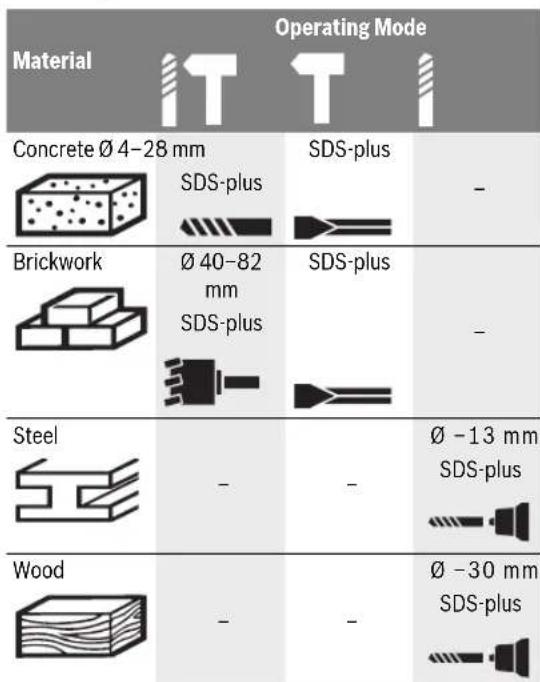
Operating Mode | Material | Concrete Ø 4-28 mm | Brickwork | Steel | Wood | |---|---|---|---|---| | - | SDS-plus | - | - | - | | - | SDS-plus | - | - | - | | - | SDS-plus | - | - | - | | - | SDS-plus | - | - | - | | - | SDS-plus | - | - | - | | - | SDS-plus | - | - | - | | - | SDS-plus | - | - | - | | - | SDS-plus | - | - | - | | - | SDS-plus | - | - | - | | - | SDS-plus | - | - | - | | - | SDS-plus | - | - | - | | - | SDS-plus | - | - | - | | - | SDS-plus | - | - | - | | - | SDS-plus | - | - | - | | - | SDS-plus | - | - | - | | - | SDS-plus | - | - | - | | - | SDS-plus | - | - | - |For hammer drilling and chiselling, SDS-plus tools are required that are inserted in the SDS-plus drill chuck.
For drilling without impact in wood, metal, ceramic and plastic as well as for screwdriving, tools without SDS-plus are used (e.g., drill bits with cylindrical shank). For these tools, a keyless chuck or a key type drill chuck are required.
GBH 3-28 DFR: The SDS-plus quick change chuck 2 can easily be replaced against the quick change keyless chuck 1 provided.
Changing the Key Type Drill Chuck (GBH 3-28 DRE)
To work with tools without SDS-plus (e.g., drills with cylindrical shank), a suitable drill chuck must be mounted (key type drill chuck or keyless chuck, accessories).
Mounting the Key Type Drill Chuck (see figure C)
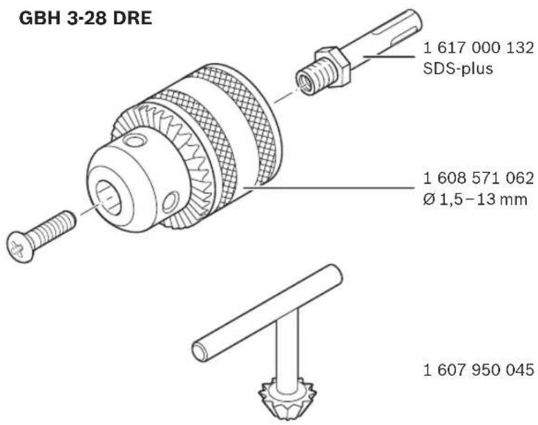
- Screw the SDS-plus adapter shank 17 into a key type drill chuck 16. Secure the key type drill chuck 16 with the securing screw 15. Please observe that the securing screw has a left-hand thread.
Inserting the Key Type Drill Chuck (see figure C)
- Clean the shank end of the adapter shank and apply a light coat of grease.
- Insert the key type drill chuck with the adapter shank into the tool holder with a turning motion until it automatically locks.
- Check the locking effect by pulling the key type drill chuck.
Removing the Key Type Drill Chuck
- Push the locking sleeve 5 toward the rear and pull out the key type drill chuck 16.
Removing/Inserting the Quick Change Chuck (GBH 3-28 DFR)
Removing the Quick Change Chuck (see figure D)
- Pull the lock ring for the quick change chuck 6 toward the rear, hold it in this position and pull off the SDS-plus quick change chuck 2 or the quick change keyless chuck 1 toward the front.
After removing, protect the replacement chuck against contamination.
Inserting the Quick Change Chuck (see figure E)
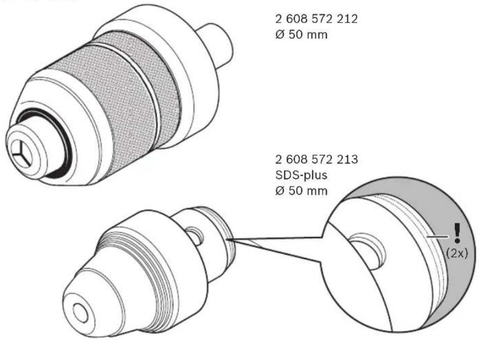
▶ Use only model-specific original equipment and pay attention to the number of identification grooves 19. Only quick-change chucks with two or three identification grooves are permitted. When an unsuitable quick-change chuck is used, the application tool could fall out during operation.
- Before inserting, clean the quick change chuck and apply a light coat of grease to the shank end.
- Grasp the SDS-plus quick change chuck 2 or the quick change keyless chuck 1 completely with your hand. Slide the quick change chuck with a turning motion onto the drill chuck mounting 18 until a distinct latching noise is heard.
- The quick change chuck is automatically locked. Check the locking effect by pulling the quick change chuck.
Changing the Tool
The dust protection cap 4 largely prevents the entry of drilling dust into the tool holder during operation. When inserting the tool, take care that the dust protection cap 4 is not damaged.
▶ A damaged dust protection cap should be changed immediately. We recommend having this carried out by an after-sales service.
Inserting SDS-plus Drilling Tools (see figure F)
The SDS-plus drill chuck allows for simple and convenient changing of drilling tools without the use of additional tools.
- GBH 3-28 DFR: Insert the SDS-plus quick change chuck 2.
- Clean and lightly grease the shank end of the tool.
- Insert the tool in a twisting manner into the tool holder until it latches itself.
- Check the latching by pulling the tool.
English | 17
As a requirement of the system, the SDS-plus drilling tool can move freely. This causes a certain radial run-out at no-load, which has no effect on the accuracy of the drill hole, as the drill bit centres itself upon drilling.
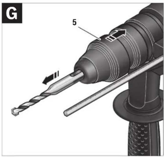
Removing SDS-plus Drilling Tools (see figure G)
- Push back the locking sleeve 5 and remove the tool.
Inserting Drilling Tools without SDS-plus (GBH 3-28 DRE)
Note: Do not use tools without SDS-plus for hammer drilling or chiselling! Tools without SDS-plus and their drill chucks are damaged by hammer drilling or chiselling.
- Insert a key type drill chuck 16 (see "Changing the Key Type Drill Chuck", page 16).
- Open the key type drill chuck 16 by turning until the tool can be inserted. Insert the tool.
- Insert the chuck key into the corresponding holes of the key type drill chuck 16 and clamp the tool uniformly.
- Turn the mode selector switch 9 to the "drilling" position.
Removing Drilling Tools without SDS-plus (GBH 3-28 DRE)
- Turn the sleeve of the key type drill chuck 16 with the drill chuck key in anticlockwise direction until the drilling tool can be removed.
Inserting Drilling Tools without SDS-plus (GBH 3-28 DFR) (see figure H)
Note: Do not use tools without SDS-plus for hammer drilling or chiselling! Tools without SDS-plus and their drill chucks are damaged by hammer drilling or chiselling.
- Insert the quick change keyless chuck 1.
- Firmly hold the retaining ring 21 of the quick change chuck. Open the tool holder by turning the front sleeve 20 until the tool can be inserted. Tightly hold the retaining ring 21 and firmly turn the front sleeve 20 in the direction of the arrow until a distinct latching noise can be heard.
- Check the tight seating by pulling the tool.
Note: If the tool holder was opened to the stop, then the latching noise possibly may be heard while closing the tool holder and the tool holder will not close.
In this case, turn the front sleeve 20 once in the opposite direction of the arrow. Afterwards, the tool holder can be closed (tightened) again.
- Turn the mode selector switch 9 to the "drilling" position.
Removing Drilling Tools without SDS-plus (GBH 3-28 DFR) (see figurel)
- Firmly hold the retaining ring 21 of the quick change chuck. Open the tool holder by turning the front sleeve 20 in the direction of the arrow until the tool can be removed.
Dust Extraction with the Dust Extraction Attachment (Accessory)
Dust from materials such as lead-containing coatings, some wood types, minerals and metal can be harmful to one's health. Touching or breathing-in the dust can cause allergic reactions and/or lead to respiratory infections of the user or bystanders.
Certain dust, such as oak or beech dust, is considered carcinogenic, especially in connection with wood-treatment additives (chromate, wood preservative). Materials containing asbestos may only be worked by specialists.
- As far as possible, use a dust extraction system suitable for the material.
- Provide for good ventilation of the working place.
- It is recommended to wear a P2 filter-class respirator.
Observe the relevant regulations in your country for the materials to be worked.
▶ Prevent dust accumulation at the workplace. Dust can easily ignite.
Mounting the Dust Extraction Attachment (see figure J)
For dust extraction, the dust extraction attachment (accessory) is required. When drilling, the dust extraction attachment retracts so that the attachment head is always close to the surface at the drill hole.
- Press the button for depth stop adjustment 10 and remove the depth stop 11. Press button 10 again and insert the dust extraction attachment into the auxiliary handle 12 from the front.
- Connect an extraction hose (diameter 19 mm, accessory) to the extraction sleeve 22 of the dust extraction attachment.
The vacuum cleaner must be suitable for the material being worked.
- When vacuuming dry dust that is especially det health or carcinogenic, use a special vacuum cleaner.
Adjusting the Drilling Depth on the Dust Extraction Attachment (see figure K)
The required drilling depth X can also be adjusted when the dust extraction attachment is mounted.
- Insert the SDS-plus drilling tool to the stop into the SDS-plus tool holder 3. Otherwise, the movability of the SDS-plus drilling tool can lead to incorrect adjustment of the drilling depth.
- Loosen the wing bolt 26 on the dust extraction attachment.
- Without switching the power tool on, apply it firmly to the drilling location. The SDS-plus drilling tool must face against the surface.
- Position the guide pipe 27 of the dust extraction attachment in its holding fixture in such a manner that the head of the dust extraction attachment faces against the surface to be drilled. Do not slide the guide pipe 27 further over the telescopic pipe 25 of the dust extraction attachment than required, so that as much as possible of the scale 25 on the telescopic pipe remains visible.
- Retighten the wing bolt 26 again. Loosen the clamping screw 23 on the depth stop of the dust extraction attachment.
- Move the depth stop 24 on the telescopic pipe 25 in such a manner that the clearance X shown in the figure corresponds with the required drilling depth.
- Tighten the clamping screw 23 in this position.


18 | English
Operation
Starting Operation
▶ Observe correct mains voltage! The voltage of the power source must agree with the voltage specified on the nameplate of the machine. Power tools marked with 230 V can also be operated with 220 V.
Setting the operating mode
The operating mode of the power tool is selected with the mode selector switch 9.
Note: Change the operating mode only when the machine is switched off! Otherwise, the machine can be damaged.
- To change the operating mode, push the release button 8 and turn the mode selector switch 9 to the requested position until it can be heard to latch.
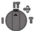
Position for hammer drilling in concrete or stone
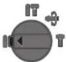
Position for drilling without impact in wood, metal, ceramic and plastic as well as for screwdriving
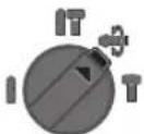
Vario-Lock position for adjustment of the chiselling position
The mode selector switch 9 does not latch in this position.
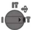
Position for chiselling
Reversing the rotational direction
The rotational direction switch 13 is used to reverse the rotational direction of the machine.
▶ Actuate the rotational direction switch 13 only when the machine is at a standstill.
Right rotation: Turn the rotational direction switch 13 to the stop in position
Left rotation: Turn the rotational direction switch 13 to the stop in position
Set the direction of rotation for hammer drilling, drilling and chiselling always to right rotation.
Switching On and Off
To save energy, only switch the power tool on when using it.
- To start the machine, press the On/Off switch 7.
- To switch off the machine, release the On/Off switch 7.
Setting the Speed/Impact Rate
The speed/impact rate of the switched on power tool can be variably adjusted, depending on how far the On/Off switch 7 is pressed.
Light pressure on the On/Off switch 7 results in low speed/impact rate. Further pressure on the switch increases the speed/impact rate.
Overload Clutch
If the tool insert becomes caught or jammed, the drive to the drill spindle is interrupted. Because of the forces that occur, always hold the power tool firmly with both hands and provide for a secure stance.
▶ If the power tool jams, switch the machine off and loosen the tool insert. When switching the machine on with the drilling tool jammed, high reaction torques can occur.
Working Advice
▶ Before any work on the machine itself, pull the mains plug.
▶ Hold the tool by the insulated gripping surfaces when performing operations where the application tool or the screw could contact hidden wiring or its own power cord. Contact with a "live" wire will also make exposed metal parts of the power tool "live" and shock the operator.
Changing the Chiselling Position (Vario-Lock)
The chisel can be locked in 36 positions. In this manner, the optimum working position can be set for each application.
- Insert the chisel into the tool holder.
- Turn the mode selector switch 9 to the "Vario-Lock" position (see "Setting the operating mode", page 18).
- Turn the tool holder to the desired chiselling position.
- Turn the mode selector switch 9 to the "chiselling" position. The tool holder is now locked.
- For chiselling, set the rotation direction to right rotation.
Inserting Screwdriver Bits (see figure L)
▶ Apply the power tool to the screw/nut only when it is switched off. Rotating tool inserts can slip off.
To work with screwdriver bits, a universal bit holder 28 with SDS-plus shank (accessory) is required.
- Clean the shank end of the adapter shank and apply a light coat of grease.
- Insert the universal bit holder with a turning motion into the tool holder until it automatically locks.
- Check the locking effect by pulling the universal bit holder.
- Insert a screwdriver bit into the universal bit holder. Use only screwdriver bits that match the screw head.
- Turn the mode selector switch 9 to the "drilling" position.
- To remove the universal bit holder, pull the locking sleeve 5 toward the rear and remove the universal bit holder 28 out of the tool holder.




English | 19
Maintenance and Service
Maintenance and Cleaning
Before any work on the machine itself, pull the mains plug.
For safe and proper working, always keep the machine and ventilation slots clean.
▶ A damaged dust protection cap should be changed immediately. We recommend having this carried out by an after-sales service.
- Clean the tool holder 3 each time after using.
If the replacement of the supply cord is necessary, this has to be done by Bosch or an authorized Bosch service agent in order to avoid a safety hazard.
After-sales Service and Application Service
Our after-sales service responds to your questions concerning maintenance and repair of your product as well as spare parts. Exploded views and information on spare parts can also be found under:
www.bosch-pt.com
Bosch's application service team will gladly answer questions concerning our products and their accessories.
In all correspondence and spare parts orders, please always include the 10-digit article number given on the nameplate of the product.
Great Britain
Robert Bosch Ltd. (B.S.C.)
P.O. Box 98
Broadwater Park
North Orbital Road
Denham
Uxbridge
UB 9 5HJ
At www.bosch-pt.co.uk you can order spare parts or arrange the collection of a product in need of servicing or repair.
Tel. Service: (0344) 7360109
E-Mail: boschservicecentre@bosch.com
Ireland
Origo Ltd.
Unit 23 Magna Drive
Magna Business Park
City West
Dublin 24
Tel. Service: (01) 4666700
Fax: (01) 4666888
Australia, New Zealand and Pacific Islands
Robert Bosch Australia Pty. Ltd.
Power Tools
Locked Bag 66
Clayton South VIC 3169
Customer Contact Center
Inside Australia:
Phone: (01300) 307044
Fax: (01300) 307045
Inside New Zealand:
Phone: (0800) 543353
Fax: (0800) 428570
Outside AU and NZ:
Phone: +61 3 95415555
www.bosch.com.au
Republic of South Africa
Customer service
Hotline: (011) 6519600
Gauteng - BSC Service Centre
35 Roper Street, New Centre
Johannesburg
Tel.: (011) 4939375
Fax: (011) 4930126
E-Mail: bsctools@icon.co.za
KZN - BSC Service Centre
Unit E, Almar Centre
143 Crompton Street
Pinetown
Tel.: (031) 7012120
Fax: (031) 7012446
E-Mail: bsc.dur@za.bosch.com
Western Cape - BSC Service Centre
Democracy Way, Prosperity Park
Milnerton
Tel.: (021) 5512577
Fax: (021) 5513223
E-Mail: bsc@zsd.co.za
Bosch Headquarters
Midrand, Gauteng
Tel.: (011) 6519600
Fax: (011) 6519880
E-Mail: rbsa-hq.pts@za.bosch.com
Disposal
The machine, accessories and packaging should be sorted for environmental-friendly recycling.
Do not dispose of power tools into household waste!
Only for EC countries:
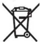
According to the European Directive 2012/19/EU for Waste Electrical and Electronic Equipment and its implementation into national right, power tools that are no longer usable must be collected separately and disposed of in an environmentally correct manner.
Subject to change without notice.
20 | Français
Français
Robert Bosch (France) S.A.S.
text_image
NOM ACCEPTED CENTRAL ANCE CERTIFIED PROJECTBoring i metal: a_h<2,5m/s^2,K=1,5m/s^2
Skruer: a_h<2,5m/s^2,K=1,5m/s^2
GBH 3-28 DFR:
Bosch Service Center
Telegrafvej 3
2750 Ballerup
På www.bosch-pt.dk kan der online bestilles reservedele eller oprettes en reparations ordre.
Tlf. Service Center: 44898855
Fax: 44898755
E-Mail: vaerktoej@dk.bosch.com
Bortskaffelse
Bosch Service Center
Telegrafvej 3
2750 Ballerup
Danmark
Tel.: (08) 7501820 (inom Sverige)
Fax: (011) 187691
Avfallshantering
| GBH 3-28 DRE | GBH 3-28 DFR |
| 3 611 B3A 0.. 3 611 B4A 0.. |
| ● | ● |
| ● | ● |
| ● | ● |
| - ● |
| W | 8 | 0 |
| min ^-1 | 0-4000 | 0-4000 |
| J | 3 | , |
| min ^-1 | 0-900 | 0-900 |
| SDS-plus SDS-plus |
| mm | 50 | 50 |
| 2017年 | 2016年 |
| mm | 28 | 28 |
| mm | 82 | 82 |
| mm | 13 | 13 |
| mm | 30 | 30 |
| kg | 3,5 | 3,6 |
| / | / |
Robert Bosch Sp. z o.o.
Bosch Service Center PT
K Vápence 1621/16
692 01 Mikulov
Tel. service scule electrice: (021) 4057540
Fax: (021) 4057566
E-Mail: infoBSC@ro.bosch.com
natural_image
Technical line drawing of a mechanical device with a shaft and lever (no text or symbols)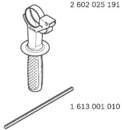
text_image
2 602 025 191 1 613 001 010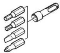
2 607 000 207
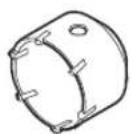
2 608 550 074 (∅ 40 mm)
2 608 550 075 (∅ 50 mm)
2 608 550 076 (∅ 68 mm)
2 608 550 077 (∅ 82 mm)
text_image
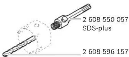
2 608 550 057 SDS-plus 2 608 596 1572 608 550 057
SDS-plus
2 608 596 157
(∅ 8 mm)
text_image
GBH 3-28 DRE 1 617 000 132 SDS-plus 1 608 571 062 Ø 1,5–13 mm 1 607 950 045GBH 3-28 DFR
text_image
2 608 572 212 Ø 50 mm 2 608 572 213 SDS-plus Ø 50 mm (2x)
| I | CE | ||
| de | EU-KonformitätserklärungBohrhammer Sachnummer | Wir erklären in alleiniger Verantwortung, dass die genannten Produkte allen einschlägigen Bestimmungen der nachfolgend aufgeführten Richtlinien und Verordnungen entsprechen und mit folgenden Normen übereinstimmen.Technische Unterlagen bei:* | |
| en | EU Declaration of ConformityRotary Hammer Article number | We declare under our sole responsibility that the stated products comply with all applicable provisions of the directives and regulations listed below and are in conformity with the following standards.Technical file at:* | |
| fr | Déclaration de conformité UEMarteau perforateur N° d'article | Nous déclarons sous notre propre responsabilité que les produits décrits sont en conformité avec les directives, règlements normatifs et normes énumérés ci-dessous.Dossier technique auprès de:* | |
| es | Declaración de conformidad UEMartillo perforador N° de artículo | Declaramos bajo nuestra exclusiva responsabilidad, que los productos nombrados cumplen con todas las disposiciones correspondientes de las Directivas y los Reglamentos mencionados a continuación y están en conformidad con las siguientes normas.Documentos técnicos de:* | |
| pt | Declaração de Conformidade CEMartelo perfurador N.° do produto | Declaramos sob nossa exclusiva responsabilidade que os produtos mencionados cumprem todas as disposições e os regulamentos indicados e estão em conformidade com as seguintes normas.Documentação técnica pertencente à:* | |
| it | Dichiarazione di conformità UEMartello perforatore Codice prodotto | Dichiariamo sotto la nostra piena responsabilità che i prodotti indicati sono conformi a tutte le disposizioni pertinenti delle Direttive e dei Regolamenti elencati di seguito, nonché alle seguenti Normative.Documentazione Tecnica presso:* | |
| nl | EU-conformiteitsverklaringBoorhamer Productnummer | Wij verklaren op eigen verantwoordelijkheid dat de genoemde producten voldoen aan alle desbetreffende bepalingen van de hierna genoemde richtlijnen en verordeningen en overeenstemmen met de volgende normen.Technisch dossier bij:* | |
| da | EU-overensstemmelseserklæringBorehammer Typenummer | Vi erklærer som eneansvarlige, at det beskrevne produkt er i overensstemmelse med alle gældende bestemmelser i følgende direktiver og forordninger og opfylder følgende standarder.Tekniske bilag ved:* | |
| sv | EU-konformitetsförklaringBorrhammare Produktnummer | Vi förklarar under eget ansvar att de nämnda produkterna uppfyller kraven i alla gällande bestämmelser i de nedan angivna direktiven och förordningar nas och att de stämmer överens med följande normer.Teknisk dokumentation:* | |
| no | EU-samsvarserklæringBorhammer Produktnummer | Vi erklærer under eneansvar at de nevnte produktene er i overensstemmelse med alle relevante bestemmelser i direktivene og forordningene nedenfor og med følgende standarder.Teknisk dokumentasjon hos:* | |
| fi | EU-vaatimustenmukaisuusvakuutusPoravasara Tuotenumero | Vakuutamme täten, että mainitut tuotteet vastaavat kaikkia seuraavien direktiivien ja asetusten asiaankuuluvia vaatimuksia ja ovat seuraavien standarden vaatimusten mukaisia.Tekniset asiakirjat saatavana:* | |
| el | Δήλωση πιστότητας EEΠεριστροφικόπιστολέτο Αριθμός ευρετηρίου | Δηλώνουμε με αποκλειστική μας ευθύνη, ότι τα αναφερόμενα προϊόντα αντιστοιχούν σε όλες τις σχετικές διατάξεις των πιο κάτω αναφερόμενων οδηγιών και κανονισμών και ταυτίζονται με τα ακόλουθα πρότυπα.Τεχνικά έγγραφα στη:* | |
| tr | AB Uygunluk beyanıKırıcı-delici Ürün kodu | Tek sorumlu olarak, tanımlanan uredrünün aşağıdaki yönetmelik ve direktiflerin geçerli bütün hükümlerine ve aşağıdaki standartlara uygun olduğunu beyan ederiz.Teknik belgelerin bulunduğu yer:* | |
CE
||
| pl | Deklaracja zgodności UEWiertarka udarowa Numer katalogowy | Oświadczamy z pełną odpowiedzialnością, że niniejsze produktyodpowiadają wszystkim wymaganiom poniżej wyszczególnionych dyrektyw irozporządzeń, oraz że są zgodne z następującymi normami.Dokumentacja techniczna:* | |
| cs | EU prohlášení o shoděVrtací kladivo Objednací číslo | Prohlašujeme na výhradní zodpovědnost, že uvedený výrobek splňujevšechna příslušná ustanovení niže uvedených směrnic a nařízení a jev souladu s následujícími normami:Technické podklady u:* | |
| sk | EU vyhlásenie o zhodeVrtacie kladivo Vecné číslo | Vyhlasujeme na výhradní zodpovednosť, že uvedený výrobok splňa všetkypríslušné ustanovenia nižšie uvedených smerníc a nariadení a je v súlades nasledujúcimi normami:Technické podklady má spoločnosť:* | |
| hu | EU konformitási nyilatkozatFúrókalapács Cikkszám | Egyedüli felelőséggel kijelentjük, hogy a megnevezett termékek megfelelnekaz alábbiakban felsorolásra kerülő irányelvek és rendeletek valamennyi ide-vágó előírásainak és megfelelnek a következő szabványoknak.Műszaki dokumentumok megôrzési pontja:* | |
| ru | Заявление о соответствии ЕСПерфоратор Товарный No | Мы заявляем под нашу единоличную ответственность, что названныепродукты соответствуют всем действующим предписаниямнижеуказанных директив и распоряжений, а также нижеуказанныхнорм.Техническая документация хранится y:* | |
| uk | Заява про відповідність ЄССПерфоратор Товарний номер | Мизаявляємо під нашу одноособову відповідальність, що названі виробивідповідають усім чинним положенням нищеозначених директив ірозпоряджень, а також нижчеозначеним нормам.Технічна документація зберігається y:* | |
| kk | ЕО сәйкестік мағлүмдамасыПерфоратор Өнім нөмірі | Өз жауапкершілікпен біз аталған өнімдер төменде жзылғандиректикалар мен жарлықтардың тиісті қағидаларына сәйкестігін жәнетөмендегі нормаларға сай екенін білдіреміз.Техникалық құжаттар:* | |
| ro | Declarație de conformitate UECiocan rotopercutor Număr deidentificare | Declarăm pe proprie răspundere că produsele mentionate corespund tuturordispozițiilor relevante ale directivelor și reglementărilor enumerate în cele ceurmează și sunt în conformitate cu următoarele standarde.Documentаție tehnică la:* | |
| bg | ЕС декларация за съответствиеПерфоратор Каталожен номер | С пълна отговорностние декларираме, че посочените продуктиотговарят на всички валидни изисквания на директивите и разпоредбипо-долу и съответства на следните стандарти.Техническа документация при:* | |
| mk | EU-Изјава за сообразностЧекани за дупчење Број на дел/артикл | Со целосна одговорност изјавуваме, дека опишаните производи се восогласност со сите релевантни одредби на следните регулативи ипрописи и се во согласност со следните норми.Техничка документација кaj:* | |
| sr | EU-izjava o usaglašenostiBušilica čекić Broj predmeta | Na sopstvenu odgovornost izjavljujemo, da navedeni proizvodi odgovarajusvim dotičnim odredbama naknadno navedenih smernica u uredaba i da su uskladu sa sledećim standardima.Tehnička dokumentacija kod:* | |
| sl | Izjava o skladnosti ESVrtalno kladivo Številka artikla | Izjavljamo pod izključno odgovornostjo, da je omenjen izdelek v skladu z vse-mi relevantnimi določili direktiv in uredb ter ustreza naslednjim standardom.Tehnična dokumentacija pri:* | |
| hr | EU izjava o sukladnostiUdarna bušilica Kataloški br. | Pod punom odgovornošću izjavljujemo da navedeni proizvodi odgovarajusvim relevantnim odredbama direktiva i propisima navedenima u nastavku ida su sukladni sa sljedećim normama.Tehnička dokumentacija se može dobiti kod:* | |
| et | EL-vastavusdeklaratsioonPuurvasar Tootenumber | Kinnitame ainuvastutajatena, et nimetatud tooted vastavad järgnevalt loetletud direktiivide ja määruste köikidele asjaomastele nõuetele ja on kooskõlasjärgmiste normidega.Tehnilised dokumentid saadaval:* | |
Bosch Power Tools 1 609 92A 2A9 | (15.6.16)
| III | CE | |||
| Iv | Deklarācija par atbilstību EK standartiemPerforators Izstrādājuma numurs | Mēs ar pilnu atbildību paziņojam, ka šeit aplūkotie izstrādājumi atbilst visiem tālāk minētajās direktīvās un rīkojumos ietvertajām saistošajām nostādnēm, kā ari sekojošiem standartiem.Tehniskā dokumentācija no:* | ||
| It | ES atitikties deklaracijaPerforatorius Gaminio numeris | Atsakingai pareiškiame, kad išvardyti gaminiai atitinka visus privalomus žemiau nurodytų direktyvų ir reglamentų reikalavimus ir šiuos standartus.Techninė dokumentacija saugoma:* | ||
| GBH 3-28 DRE | 3 611 B3A 0.. | 2006/42/EC | EN 60745-1:2009+A11:2010 | |
| 2014/30/EU | EN 60745-2-6:2010 | |||
| GBH 3-28 DFR | 3 611 B4A 0.. | 2011/65/EU | EN 55014-1:2006+A1:2009+A2:2011EN 55014-2:1997+A1:2001+A2:2008EN 61000-3-2:2014EN 61000-3-3:2013EN 50581:2012 | |
| BOSCH | *Robert Bosch Power Tools GmbH (PT/ETM9)70538 StuttgartGERMANY | |||
| Henk BeckerExecutive Vice President Engineering | Helmut HeinzelmannHead of Product Certification | |||
| Robert Bosch Power Tools GmbH, 70538 Stuttgart, GERMANYStuttgart, 01.01.2017 | ||||
