USER MANUAL NEO 3000 2600W SDMO
(Translation of the original note)
(Versta is originalo)
Lietosanas un apkopes
rokasgramata
| Contents |
| 1. Preface | 7. Maintenance procedures |
| 2. General description | 8. Storing the generating set |
| 3. Preparation before use | 9. Troubleshooting |
| 4. Using the generator set | 10. Specifications |
| 5. Safety features | 11. Cable sizes |
| 6. Maintenance schedule | 12. EC Declaration of conformity |
1. Preface
1.1. Recommendations
| Warning | | Read this manual carefully before use.
The safety advice and the usage and maintenance instructions for the generating set must always be strictly adhered to. |
The information contained in this manual is taken from technical data available at the time of print. In line with our policy of continually improving the quality of our products, this information may be amended without warning.
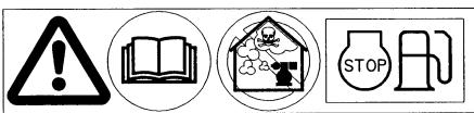
1.2. Pictograms and plates on the generating sets and what they mean
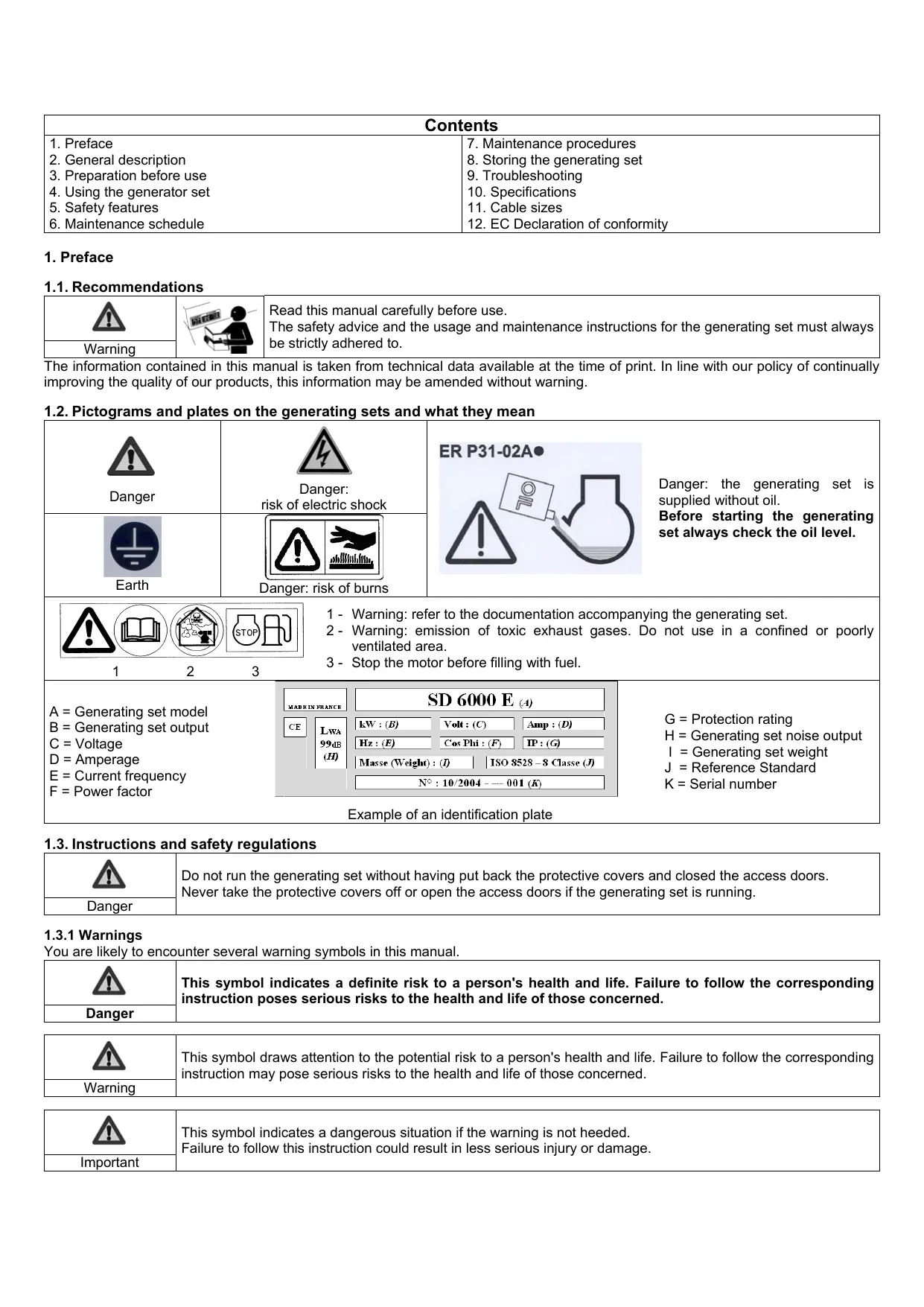
| Danger | Danger: risk of electric shock | ER P31-02A
Danger: the generating set is supplied without oil.
Before starting the generating set always check the oil level. |
| Earth | Danger: risk of burns |
| A = Generating set model
B = Generating set output
C = Voltage
D = Amperage
E = Current frequency
F = Power factor | MADE IN FRANCE
CE LWA 99dB (H) | SD 6000 E (4) | G = Protection rating
H = Generating set noise output
I = Generating set weight
J = Reference Standard
K = Serial number |
| kW : (B) Volts : (C) Amp : (D) Hz : (E) Cos Phi : (F) IP : (G) Masse (Weight) : (J) ISO 8528 - 8 Classe (J) N° : 10/2004 - - - 001 (K) |
| Example of an identification plate |
1.3. Instructions and safety regulations
| Danger | Do not run the generating set without having put back the protective covers and closed the access doors. Never take the protective covers off or open the access doors if the generating set is running. |
1.3.1Warnings
You are likely to encounter several warning symbols in this manual.
| This symbol indicates a definite risk to a person's health and life. Failure to follow the corresponding instruction poses serious risks to the health and life of those concerned. |
| Danger | |
| Warning | This symbol draws attention to the potential risk to a person's health and life. Failure to follow the corresponding instruction may pose serious risks to the health and life of those concerned. |
| This symbol indicates a dangerous situation if the warning is not heeded.
Failure to follow this instruction could result in less serious injury or damage. |
| Important | |
1.3.2 General advice
On taking delivery of the generating set, check that it is complete and not damaged in any way. A generating set should be handled gently and brusque movements should be avoided. Ensure that the place where it is to be stored or used is carefully prepared beforehand.
| Warning | Before use:
- make sure you know how to stop the generating set in the event of an emergency,
- make sure you completely understand all the controls and operations. |
For reasons of safety, the maintenance intervals must be respected (see Maintenance table). Never carry out repairs or maintenance procedures without the necessary experience and/or tools.
Never let other people use the generating set without having given them all the necessary instructions beforehand.
Never let children touch the generating set, even when it is not in operation. Do not operate the generating set near animals (as it could cause them to panic or frighten them).
Never start the engine without an air filter or exhaust.
Never invert the positive and negative terminals on the battery (if fitted) when fitting them as this could cause serious damage to the electrical equipment.
Never cover the generating set with any type of material while it is in operation or just after it has been turned off. Wait until the motor is cold.
Never coat the generating set with oil, even to protect it from corrosion; preservative oils are flammable and can be dangerous if inhaled.
In all cases, respect the local regulations currently in place concerning the use of generating sets.
1.3.3 Safety guidelines to prevent fire
| Danger | | Never operate the generating set in areas containing flammable products (risk of sparks).
Keep all flammable products (petrol, oil, fabric etc.) out of the way when the unit is in operation.
Never cover the generating set with any type of material while it is in operation or just after it has been turned off: always wait until the engine cools down. |
1.3.4 Safety guidelines against burns
| Warning | Never touch the engine or the silencer while the generating set is in operation, or when it has just stopped. |
Hot oil burns; avoid contact with the skin. Before carrying out any operation, check that the system is no longer pressurised. Never start or run the engine if the oil filler cap is off (oil may splash out).
1.3.5 Safety guidelines to prevent electrocution
| Danger | The generating sets supply electrical current when in operation: risk of electrocution. |
| |
Never touch stripped cables or disconnected connectors. Never handle a generating set with wet hands or feet. Never expose the equipment to liquid splashes or rainfall, and do not place it on wet ground.
Always keep electric cables and connections in good condition. Never use equipment in poor condition: risk of electrocution or damage to the equipment.
Specific protective measures to follow in accordance with the operating conditions.
1 – If the generating set is not equipped with an integrated differential protection device at delivery
In the case of occasional use of one or many mobile or rotating devices, the earthing of the generating set is not necessary, but the following installation rules must be complied with:
a) The grounds of the equipment connected to the outlets of the generating set must be interconnected with the ground of the set by a protection conductor. This equipotentiality is performed if all the connecting cables of class I equipment are fitted with a PE protection conductor (GREEN and YELLOW) correctly connected to their patches to the generating set (this protection conductor is not necessary for equipment of class II protection). The good condition of the cables and the ground connections is an essential element to guarantee protection against electric shocks, therefore the usage of rubber sheathed cables is strongly recommended, flexible and strong, in compliance with standard IEC 60245-4 Comply with the cable lengths indicated in the table of the paragraph "Cable sizes".
b) Each channel (electrical cable) originating from the generating set must be protected by a complementary differential device calibrated at 30mA , set up before each outlet less than 1m from the set, and protected against external influences to which it could be subjected.
2 - If the generating set is equipped with an integrated differential protection device at delivery (with the alternator ground connected to the earth terminal of the generating set)
In the case of occasional use of one or many mobile or rotating devices, the earthing of the generating set is not necessary, but the ground connection rules listed in point a) of paragraph 1 above must be complied with.
In the case of the supply of a temporary or semi-permanent station (site, show, fairs.), connect the ground of the generating set to the earth and follow the rules listed in point a) of paragraph 1 above.
In the case of the emergency re-supply of a fixed installation, the connection of the generating set to the ground of the installation to re-supply and the electrical connection must be performed by a qualified electrician, in compliance with the regulation applicable on the installation site. Do not connect the generating set directly to other power sources (e.g.: public distribution network); install a power inverter.
Mobile applications (example: generating set installed in a moving vehicle)
If earthing is not possible, the grounds of the vehicle and of the equipment connected to the outlets of the generating set must be interconnected with the ground of the generating set by a protection conductor, in compliance with the ground connection rules listed at point a) of paragraph 1 above.
The protection against electric shocks is performed by circuit breakers provided specially for the generating set: if necessary, replace them with circuit breakers having the same ratings and characteristics.
1.3.6 Danger of moving parts
| Danger | | Never go near a moving part that is in operation if you have loose clothing or long hair that is not enclosed in a protective hair net.
Do not try to stop, slow down or impede a moving part when it is in operation. |
1.3.7 Safety guidelines for exhaust gases
| Danger | The carbon monoxide present in the exhaust gas may lead to death by inhalation if the concentration levels in the atmosphere are too high.
Always use the generating set in a well ventilated area where the gases cannot accumulate. |
For safety reasons and for correct operation of the generating set, correct ventilation is essential (risk of intoxication, engine overheating and accidents involving, or damage to, the surrounding equipment and property). If it is necessary to operate it inside a building, the exhaust gases must be evacuated outside and adequate ventilation must be provided so that any people or animals present are not affected.
1.3.8 Operating conditions
The stated outputs of the generating sets are obtained under the reference conditions outlined in ISO 8528-1(2005):
Total barometric pressure: 100 Kpa
✓ Air ambient temperature: 25^ (298K)
Relative humidity: 30%
Generating set performance is reduced by approximately 4% for every additional 10^ C and/or approximately 1% for every additional 100m in altitude.
1.3.9 Capacity of the generating set (overload)
Never exceed the rated load of the generating set (in Amps and/or Watts) when it is running continuously.
Before connecting and operating the generating set, calculate the electrical power required by the electric appliances (in Watts). This electrical power rating is usually found on the manufacturer's plate on bulbs, electrical appliances, motors etc. The sum total of power required by these appliances should not exceed the nominal power rating of the generating set.
1.3.10 Protecting the environment
Drain the engine oil into a designated container: never drain or discard engine oil onto the ground.
As far as possible, avoid sound reverberating through walls or buildings (the noise will be amplified).
If the generating set is used in wooded, bushy or uncultivated areas and if the exhaust silencer is not fitted with a spark arrester, clear any vegetation away from the area and take care that the sparks do not cause a fire.
1.3.11 Filling with fuel
| Danger | The fuel is highly flammable and its vapours are combustible.
Filling should be carried out with the engine turned off. Smoking, using a naked flame or producing sparks are forbidden while the fuel tank is being filled.
All traces of fuel should be wiped off with a clean cloth. |
Storage and handling of petroleum products must be carried out in accordance with the law. Close the fuel tap (if fitted) each time the tank has been filled. Never top up fuel when the generating set is in operation or hot.
Always place the generating set on a flat, level and horizontal surface to avoid fuel spilling onto the motor. Fill the tank with a funnel taking care not to spill the fuel, then screw the plug back onto the fuel tank.
1.3.12 Safety guidelines for handling batteries
| Danger | | | Never leave the battery close to a flame or fire.
Use only insulated tools.
Never use sulphuric acid or acid water to top up the electrolyte level. |
- General description
| Figure A |
| Earth connection (no.1) | MAX / ECO Mode (no. 9) |
| Inspection cover (no.2) | Tank pressurisation pump (no.10) |
| Fuel tap (no.3) | Indicator lamps (no.11)
A. Operating light
B. Overload indicator
C. Oil safety indicator |
| Fuel tank aeration pointer (no.4) |
| Fuel tank cap (no.5) |
| Choke (no.6) |
| Recoil starter (no.7) | Spark plug access cover (no.12) |
| Electrical socket (no.8) | Muffler (no.13) |
| Figure B |
| Inspection trap cover (no.1) | Oil filler and drain plug (no.2)
Maximum oil filling level |
| Figure C |
| Fuel tank aeration pointer RUN / START (no. 1) | Fuel filter (no. 4) |
| Tank pressurisation pump (no.2) |
| Fuel strainer (no.3)
Maximum fuel filling level |
| Figure D |
| Air filter cover (no.1) | Filter element (no.2)
Filter element cleaning |
| Figure E |
| Spark plug access cover (no.1) | Spark plug (no. 2) |
3. Preparation before use
3.1. Positioning the generating set for operation
Choose a site that is clean, well ventilated and sheltered from bad weather.
Place the generating set on a flat, horizontal surface which is firm enough to prevent the set sinking down (under no circumstances should the set tilt in any direction by more than 10^ ).
Store the additional supplies of oil and fuel within close proximity, whilst maintaining a certain distance for safety.
3.2. Earthing the generating set
| Danger | The generating sets supply electrical current when in operation: risk of electrocution. Connect the generating set to the ground at each use. |
|
To connect the set to the ground: Attach a 10mm^2 copper wire to the set's earth connection and to a galvanised steel earthing rod driven 1 meter into the ground.
3.3. Checking the oil level
| Important | Before starting the generating set, always check the level of engine oil.
Supplement it with the recommended oil (see § Specifications) with the help of a funnel, up to the upper limit of the gauge. |
Open the inspection cover (fig. A - no. 2).
Unscrew the oil filler plug (fig. B - no. 2).
3 Check the oil level.
4 If necessary supplement it.
Screw back the filler plug.
Wipe any excess oil with a clean cloth.
7 Close the inspection cover (fig. A - no. 2).
3.4. Checking the fuel level
| Danger | The fuel must be refilled when the engine is off and according to safety guidelines (see § Filling with fuel). Before opening the fuel tank cap, always set the fuel tank aeration pointer to the RUN position. |
1 Close the fuel tap (fig. A - no.3).
2 Set the fuel tank aeration pointer to RUN position (fig. A - no. 4 & fig. C - no. 1).
3 Unscrew the fuel tank cap (fig. A - no. 5).
Check the fuel level. Taking care not to spill the fuel, use a funnel to fill the tank up to its filling limit.
| Use only clean fuel without any water.
Do not overfill the tank (there should not be any fuel in the filler neck).
After the tank has been filled, always ensure that the filler plug is properly tightened.
If any fuel has been spilt, make sure that it has dried and that any vapours have cleared before starting up the generating set. |
| Important | |
Screw the fuel tank cap back onto the fuel tank.
3.5. Checking the air filter
| Before starting the generating set, check the air filter. |
| Important | |
1 Open the inspection cover (fig. A - no. 2)
Unlock the air filter and remove its cover (fig. D - no. 1).
3 Check the condition of filter element, if necessary clean it (see § Cleaning of air filter).
4. Using the generator set
| Warning | Before use:
- make sure you know how to stop the generating set in the event of an emergency,
- make sure you completely understand all the controls and operations. |
4.1. Starting procedure
To restart the generating set after a stoppage of more than 10min or when the fuel level has come down by at least half the tank level, pressurise the fuel tank by using the pressurisation pump (see Usage of tank pressurisation pump).
Check that the generating set is properly earthed (fig. A- no. 1 & see § Earthing the generating set).
2 Set the fuel tank aeration pointer to RUN position (fig. A - no. 4 & fig. C - no. 1).
3 Open the fuel tap (fig. A - no.3).
4 Set the choke (fig. A - no.6) to « V » position.
N.B: Do not use the choke when the engine is hot or when the atmospheric temperature is high.
Gently pull the recoil starter once (fig. A - no. 7) until resistance encountered, allow it to return back slowly.
⑥ Then, pull the recoil starter quickly and powerfully until the engine starts-up.
Slowly place the choke in « | » position and wait until the engine temperature begins to rise before using the generating set.
4.1.1 Usage of tank pressurisation pump
The fuel tank must be pressurised using the pump:
When the generating set has stopped for more than 10 minutes,
- When the fuel level is lower than half of the tank.
| ! | Never use the pump to pressurize the fuel tank when the fuel level is more than half of the tank (risk of damaging the generating set). |
| Important |
1 Set the fuel tank aeration pointer to START (fig. C - no. 1).
2 Actuate the tank pressurisation pump several times (fig. C - no. 2).
3 Start the generating set without setting the ventilation slider to RUN (see § Start-up procedure).
4 Immediately set the fuel tank aeration pointer to RUN (fig. C - no. 1) following the start-up of the generating set.
4.2. Operation
When the generating set is warm and the running speed has stabilised (after approximately 3 minutes):
1 Check that the operating light is turned on (fig. A - no. 11, A).
2 Activate the "MAX" or "ECO" mode (fig. A - no. 9).
3 Connect the devices to the generating set sockets (fig. A - no. 8).
In case of overload or short-circuit, the operating light (fig. A - no. 11, A) switches-off and the overload indicator (fig. A - no. 11, B) glows: Stop the generating set and eliminate the overload or the short-circuit.
4.2.1 MAX-ECO mode
MAX
When the button (Fig. A - No. 9) is set to "MAX", the generating set can quickly respond to a high inrush current (when running under no load, it runs at 3800 rpm).
ECO
The "ECO" position is useful for small loads. To reduce noise emissions, the generating set runs at its min. speed (3000 rpm) between 0 and 200 W. When a power above 200 W is required, the speed of rotation gradually increases.
4.3. Switching off
1 Shut down and disconnect the devices.
2 Allow the engine to run idle for 1 or 2 min.
3 Close the fuel tap (fig. A - no.3).
The generator set comes to a stop.

Warning
Always ensure suitable ventilation for the generating set. Even after shut down, the engine continues to dissipate heat.
5. Safety features
5.1. Oil cut-out
If there is no oil in the engine sump or if the oil pressure is low, the oil safety mechanism automatically stops the engine to prevent any damage.
If this occurs, check the engine oil level and top it up if necessary before looking for any other cause of the problem.
5.2. Circuit breaker
The set's electrical circuit is protected by one or more magnetothermal, differential or thermal cut-out switches. In the event of an overload and/or short circuit, the supply of electrical energy may be cut.
If necessary, replace the circuit breakers in the generating set with circuit breakers with identical nominal ratings and specifications.
6. Maintenance schedule
6.1. Reminder of use
The maintenance operations to be carried out are described in the maintenance schedule. The interval for this is supplied as a guide and for generating sets operating with fuel and oil which conform to the specifications given in this manual.
If the generating set is used under extreme conditions, the interval between the maintenance operations must be shortened.
6.2. Maintenance table
| Component | Operations to be carried out on reaching the \(1^{st}\)due date | With each usage | Every month or Every 10 hours | Every 3 months or Every 50 hours | Every year or Every 300 hours |
| Generating set | Cleaning | | | ● | |
| Engine oil | Check the level | ● | | | |
| Renew | | | ● | |
| Fuel strainer | Cleaning | | ● | | |
| Air filter | Checking | ● | | | |
| Cleaning | | ● | | |
| Spark plug | Check and clean | | | ● | |
| Valves* | Checking* | | | ● | |
| Warning | Before carrying out any maintenance operation:
- switch off the generating set.
- disconnect the cap(s) of the spark plug(s) and disconnect the starter battery (if fitted). |
Only use original parts or equivalent parts: risk of damage to the generating set.
7.1. Checking bolts, nuts and screws
To prevent faults or breakdowns, carefully check all the nuts, bolts and screws on a daily basis.
1 Inspect the entire generating set before and after each use.
2 Tighten any loose nuts or bolts.
Danger: The cylinder head bolts must be tightened by a specialist. Refer to the agent for your region.
7.2. Renewing the engine oil
Adhere to the environment protection guidelines (see Protecting the environment) and drain the oil into an appropriate container.
1 Open the inspection cover (fig. A - no. 2).
With the engine still warm, remove the filler and drain plug (fig. B - no. 2).
Gently tilt the generating set to empty the oil into the appropriate container.
After complete draining, fill it with the recommended oil (see § Specifications), check the level.
5 Refit the filler and drain plug (fig. B - no. 2).
Check for oil leakage.
Wipe any oil traces with a clean cloth.
Close the inspection cover.
7.3. Cleaning the fuel strainer
| Danger | Do not smoke, or create sparks. Keep away from open flames. Check for absence of leakage, wipe out any fuel traces and ensure that the vapours are cleared-up before starting the generating set. |
1 Close the fuel tap (fig. A - no.3)
2 Remove the fuel tank cap and the strainer (fig. C - no.3).
3 With a low pressure dry air gun, from outside blow air inwards on to the strainer.
4 Rinse with clean fuel.
Put back the strainer in place and carefully screw back the fuel tank cap.
7.4. Replacing the fuel filter
| Danger | Do not smoke, or bring naked flames or generate sparks nearby. Check that there are no leaks, wipe off any trace of fuel and ensure that the vapours have dissipated before restarting the generating set. |
Close the fuel tap (fig. A - no. 3).
Observe the direction of fitting for the filter.
3 Release the fuel filter from its support bracket (fig. C - no. 4).
4 Remove the fuel pipes on either side of the filter and use a suitable container to collect the fuel.
Fit a new filter, observing the direction of fitting.
6 Open the fuel tap and check that there are no leaks.
7.5. Cleaning the air filter
| Important | Never use petrol or flammable solvents for cleaning the air filter element (risk of fire or explosion). |
1 Remove the inspection cover (fig. A - no. 2).
2 Remove the filter cover (fig. D - no. 1).
3 Remove the filter element (fig. D - no. 2) and check the type of clogging:
Dry clogging:
Use a low-pressure dry compressed air gun to blow from the inside of the filter element out, moving from the top to the bottom until there is no more dust.
Check the condition of the filter element: replace it if it is at all damaged.
3 Refit the filter element and its cover.
Put back the inspection cover.
Moist/oily clogging:
1 Replace the filter element.
2 Refit the filter element and its cover.
Put back the inspection cover.
7.6. Checking the spark plug
1 Open the spark plug access cover (fig. E - no. 1), and fit the spark plug with the help of a plug spanner.
Check the condition of the spark plug (fig. E - no. 2): If the electrodes are worn or if the insulation is split or flaking:
3 Replace the spark plug.
Fit a new spark plug in position and tighten it by hand to avoid damaging the threads.
Use a spark plug spanner to tighten the spark plug by 1/4-1/2 turn after it is seated to compress the washer.
3 Clean the spark plug with a metal brush.
Check the condition of the washer.
Otherwise:
4 With a feeler gauge, check the electrode gap "X": it must be between 0.6 and 0.8mm inclusive.
Fit the spark plug in position and tighten it by hand to avoid damaging the threads.
Use a spark plug spanner to tighten it by 1/4-1/2 turn after it is seated to compress the washer.
7.7. Cleaning the generating set
| Important | Cleaning with a water jet is not recommended.
Cleaning with high pressure cleaning equipment is forbidden. |
1 Remove all dust and debris from around the exhaust.
2 Clean the generating set, particularly the alternator and engine air inlets and outlets, using a cloth and brush.
3 Check the general condition of the generating set and replace any faulty parts.
8. Storing the generating set
In case of prolonged non-usage of the generating set, carry out storage operations in accordance with the guidelines given below.
1 Drain all the fuel from the fuel tank into a suitable container.
2 Run the engine till it stops due to lack of fuel.
3 Renew the engine oil.
4 Remove the spark plug (fig. E - no. 2) and pour around 15ml of engine oil into the cylinder through the spark plug opening.
5 Refit the spark plug.
Pull the recoil starter handle 3 to 4 times (fig. A - no. 7) to completely drain-out the carburetor and distribute the oil inside the cylinder.
7 Clean the exterior of the generating set and cover it with the protection cover in order to protect it from dust.
Store the generating set in a clean and dry spot.
- Troubleshooting
| Problems | Probable cause | Possible solutions |
| The engine does not start | Load connected to the generating set while starting. | Disconnect the load |
| The oil level is too low. | Check the oil level and top up if necessary. |
| Insufficient fuel level | Fill-up fuel (see § Filling with fuel) |
| Fuel feed system blocked or elusive | Check, repair or replace.* |
| Air filter blocked | Clean the air filter |
| The engine stops | Ventilation openings blocked | Clean the suction and discharge guards |
| The oil level is too low. | Check the oil level and top up if necessary. |
| Overload indicator (fig. A – no. 11) turned on: overload. | Eliminate the overload and wait for 30sec before restarting. |
| No electric current | Defective device power supply cord. | Change the cord. |
| Defective electrical socket. | Check, repair or replace.* |
| Defective alternator. | Check, repair or replace.* |
| Model | QNEO 3000 |
| Type of Engine | OLYMP ES 128-1 |
| Maximum output / Rated output | 2600 W / 2100 W |
| Direct Current | 12V-5A |
| Alternating Current | 230V-9.2A |
| Socket type | 2 x 2P+T - 10/16A - 230V |
| Circuit-breaker | ● |
| Oil cut-out | ● |
| Battery | X |
| Acoustic pressure level at 1 m in dB(A) | 73 dB(A) |
| Weight in kg (without fuel) | 24 |
| Dimensions L x w x h in cm | 59 x 30 x 55 |
| Recommended oil | SAE 15W40 |
| Oil sump capacity in litres | 0.55 |
| Recommended fuel | Unleaded petrol |
| Fuel tank capacity in litres | 4.3 |
| Spark plug | CHAMPION : RN9YC / NGK :BPR6ES |
: standard
o : optional
X: not possible
- Cable sizes
| Laying mode = cables on cable tray or racks not perforated / admissible voltage drop = 5% / Multiconductors.
Cable type PVC 70°C (example H07RNF) / Ambient temperature =30°C. |
| Rated Current (A) | Cable lengths |
| 0 to 50m | 51 to 100m | 101 to 150m |
| mm2 / AWG | mm2 / AWG | mm2 / AWG |
| Single-phase | Three-phase | Single-phase | Three-phase | Single-phase | Three-phase |
| 10 | 4 / 10 | 1.5 / 14 | 10 / 7 | 2.5 / 12 | 10 / 7 | 4 / 10 |
| 16 | 6 / 9 | 2.5 / 12 | 10 / 7 | 4 / 10 | 16 / 5 | 6 / 9 |
| 20 | 10 / 7 | 2.5 / 12 | 16 / 5 | 4 / 10 | 25 / 3 | 6 / 9 |
| 25 | 10 / 7 | 4 / 10 | 16 / 5 | 6 / 9 | 25 / 3 | 10 / 7 |
| 32 | 10 / 7 | | 25 / 3 | | 35 / 2 | |
| 40 | 16 / 5 | 35 / 2 | 50 / 0 |
| 50 | 16 / 5 | 35 / 2 | 50 / 0 |
| 63 | 25 / 3 | 50 / 0 | 70 / 2 / 0 |
Name and address of manufacturer: SDMO, 12 bis rue de la Villeneuve, CS 92848, 29228 BREST CEDEX 2, FRANCE.
| Description of the equipment | Generating set |
| Make | SDMO |
| Type | INEO 3000 |
Name and address of the person authorised to create and keep the technical file
G. Le Gall, SDMO, 12 bis rue de la Villeneuve, CS 92848, 29228 BREST CEDEX 2, FRANCE
G. Le Gall, the manufacturer's authorised representative, hereby declares that the product conforms to the following EU Directives:
2006/42/EC / Machinery Directive.
2006/95/EC / Low Voltage Directive.
2004/108/EC / Directive on Electromagnetic Compatibility.
2000/14/EC / Directive relating to the Noise Emission of Outdoor
Equipment.
For the directive 2000/14/EC
Notified body:
CETIM
BP 67 F60304 - SENLIS.
Compliance procedure: Appendix VI.
Sound power level guaranteed (Lwa): 96 dB(A).
Rated output: 2100 W
01/2010 - G. Le Gall

Indices
2006/95/CE / Norm laagspanning.
A=MoIeJIb reHepaTopHOy yCTaHOBKN
B=MoUHOCb reHepaTOpHOyUCTaHOBKN
C = HanpЯЖeHne ToKa
D = Cúna toka
E = Yactota toka
F = Ko3φΦnζηENT MOζHQCTN
Пример undeHTnФИкAUsoHNoHToTabIuYKn
| MADE IN FRANCE | SD 6000 E (4) |
| CE | LWA | kW: (B) | Volt: (C) | Amp: (D) |
| 99 dB | Hz: (E) | Cos Phi: (F) | IP: (G) |
| (H) | Masse (Weight): (I) | ISO 8528-8 Classe (J) |
| | N°: 10/2004 -- 001 (K) |
G = Knaacc 3aunTbI
H = 3BykoBoe ДаВлЕнHe, CO3ДаBaEMо reHepaTOpHoi yCTaHOBkoI
I = Macca rehepaTopHou yCTaHOBKN
J = COOTBETCTBnE CTaHdApTy
K = CepiHbI Homep
1.3. Празвлaja Textнки 6e3oNaChOCTn
| Anachoctb | HиВ Коем слычae He Bключайte rehepaTopHyю уctaHOBky, He yctaHOBnB Ha MeCTO 3aцIntье панели/n/Nлп He 3akpbIb BCE TOUKN DoCTуna.HиВ Коем слычан He ChИмайte 3aцIntьe панели/n He OTkpblBaIte ToUKN DoCTуna, ecnlne rehepaTopHЯ уctaHOBka pa60Taet. |
1.3.1 PpeynpeKdeHn
B daHnomykoBoNDCTBe Moryt nCnoIb3ObaTbcpa3nNHyIe npedynpexdaHoune CmMBoJIbI.
1.3.4 MepbI 3aunTbI OT OXOTOB
1.3.7 MepbI 3aunTbI OT Otpa6oTaBux ra3OB
5.3aunthbIe yctpoCTBa
5.1.YCTPOICTBO6e3ONaCHOCTN CNTEmbl Cma3KN
PnO TCTBnMa B KapTepe DnurTaTeJI NnI Pn CnUkOM Hn3KOM DaBJeHm MacNa, CNCTema KOHTPOJMa MACa ABTomatueckn OCTaHaBJIbAeT DnurTaTeJI BO n36ekAHne IIO6bIX NOBpeXdeHm.
B TAKOM Cnyuae, CneJyET npOBepntb ypOBeHb Macna B KapTepe DnurTaTeJI N DOBeCTN erO Do HOpMbI, B Cnyuae Heo6xOIMOCtN, PpeJde Yem npICTynaTb K nonCKy INOH pInuHb IHeNCnPabHOCTN.
5.2.BbIKJIOyateJIb
3JIeKtpnueckar cenb rehepaTOPHO yCTaHOBKn 3aunuHe OJHM nIHN HeCKoJIbKIMN TepMOMaHHTbIMN, dIΦpepeHuaNbHbIMN nIIN TeJIOBbIMN BbIKNUOaTeJAMN. Ipn neperpy3ke CETn /nIIN KOPOTKOM 3aMbIkaHNI NOdaa 3NeKTPo3Heprm MoKeT 6bITIpeKpAuneHa.
B cnyuae Heo6xOIMOCTn 3aMeHnte BbIKIOUaTeI IN reHepaTOPOH yCTaHOBKn Ha BbIKIOUaTeI N C TaKIMN Xe HOMHaJIbHBiIMN 3NaueHnA Mn I xapaKTepNCtIKaMn
7.5.OuHCTKa BO3dUwHOrO 1nIbTpTa
EcIn CBeya 3axnraHnC n3HOseHHbIMn 3NeKTPoJaMn, ONJIaBJIeHHbIM INI ONCTaINBaIOUcMcN3OJIaTOpOM:
3aMeHnTe CBeyu.
UyctahOBHTe Ha MeCTO HOByo CBeUy 3aJnraHnI n 3aBepHnTe ee ot pyKn, YTObI He NOBpeDntb pe3b6y.
⑤ДовернITE CBeyC NOMOьв CBeyHOrO KInOua Ha 1/4 - 1/2 obopota, yTo6bI CkaTb IaN6y.
B npotNBHom cnyuae:
OuNCTnTe CBeUy MeTaJIInueCKoI 电TkoI.
C NOMOJIbU ΜΥΝΑ NOBΕρβTe 3a3Op «X» MeЖДу 3JIeKTpOДAMN: OH DoJIXeH COCTaBPlrTb 0,6-0,8 MM.
5 Pnpoepe coctoHne wai6bl.
⑥ YctahOBHTe Ha MecTo CBeU 3axnraHnI 3aBepHnte ee OT pyKN, yTObI He NOBpeNTb pe3b6y.
7 OboepHnte Cbeyu c NOMOuBcBeuHoro KInouHa Ha 1/4 - 1/2 obopota, yTo6bI cKaTb IaN6y.
7.7.OuHCTka reHepaTOPHOyCTaHOBKn
UpoBHeb rapaHTnpOBaHHo akyCTnueCKO MoUHOCTN
(Y3M) : 96 έB(A).
1
2
as pa: fare for forbraending.