RBC52FSB, RBC52SB - Brush cutter RYOBI - Free user manual and instructions
Find the device manual for free RBC52FSB, RBC52SB RYOBI in PDF.



| Product Type | Brushcutter / Trimmer |
| Brand | RYOBI |
| Model | RBC52FSB, RBC52SB |
| Weight (without fuel or cutting system) | 7.52 kg |
| Weight (without fuel, with blade) | 7.87 kg |
| Weight (without fuel, with trimmer head) | 7.72 kg |
| Tank capacity | 1230 cm³ |
| Cutting width | 415 mm |
| Displacement (RBC52SB) | 51.7 cc |
| Displacement (RBC40SB - not applicable) | 40 cc |
| Max. engine power (RBC52SB) | 1.4 kW / 1.9 HP |
| Max. rotation speed | 10,000 rpm |
| Engine speed at max. speed | 12,500 rpm |
| Idle speed | 2,250 - 2,750 rpm |
| Fuel consumption at max. power | 0.85 kg/h |
| Vibration level (full throttle, left handle) | 7.2 m/s² |
| Vibration level (full throttle, right handle) | 7.5 m/s² |
| Sound pressure (EN ISO 11806) | 102 dBA |
| Sound power (ISO 10884) | 115 dBpA |
| Fuel | 2-stroke gasoline/oil mixture (30:1) |
| Engine type | Air-cooled 2-stroke engine |
| Cutting device | 3-tooth blade or trimmer head (2.7 mm line) |
| Safety | Grass deflector, blade guard, harness, engine stop |
| Maintenance | Washable air filter, annual spark plug, fuel drain for storage |
| Warranty | 24 months |
Frequently Asked Questions - RBC52FSB, RBC52SB RYOBI
User questions about RBC52FSB, RBC52SB RYOBI
0 question about this device. Answer the ones you know or ask your own.
Ask a new question about this device
Download the instructions for your Brush cutter in PDF format for free! Find your manual RBC52FSB, RBC52SB - RYOBI and take your electronic device back in hand. On this page are published all the documents necessary for the use of your device. RBC52FSB, RBC52SB by RYOBI.
USER MANUAL RBC52FSB, RBC52SB RYOBI
Important!
It is essential that you read the instructions in this manual before mounting and operating this machine.
| Attention ! | Il est indispensable que vous lisiez les instructions contenues dans ce manuel avant le montage et la mise en service de l'appareil. |
| Important! | It is essential that you read the instructions in this manual before mounting and operating this machine. |
| Achtung! | Bitte lesen Sie unbedingt vor Montage und Inbetriebnahme die Hinweise dieser Bedienungsanleitung. |
| ¡Atención! | Es imprescindible que lea las instrucciones de este manual antes del montaje y de la puesta en servicio. |
| Attenzione! | Prima di procedere al montaggio e alla messa in funzione, è indispensabile leggere attentamente le istruzioni del presente manuale. |
| Atenção! | É indispensável ler as instruções deste manual antes de montar e pôr em serviço. |
| Let op ! | Het is absoluut noodzakelijk vóór montage en inbedrijfstelling de aanwijzingen in deze handleiding te lezen. |
| Observera! | Det är nödvändigt att läsa instruktionerna i denna bruksanvisning före montering och driftsättning. |
| OBS! | Denne brugsanvisning skal læses igennem inden montering og ibrugtagning. |
| Advarse! | Vennligst les instruksjonene i denne bruksanvisningen før du monterer og tar i bruk maskinen. |
| Huomio! | On ehdottoman válttämätöntä lukea tässä käyttöohjeessa annetut ohjeet ennen asennusta ja käyttöönottoa. |
| Προσοχή! | Είναι απαραίτητο να διαβάσετε τις συστάσεις των οδηγιών αυτών πριν τη συναρμολόγηση και τη θέση σε λειτουργία |
| Figyelem! | Feltétlenül fontos, hogy a jelen használati útmutatóban foglalt előírásokat az összeszerelés és az üzembe helyezés ellőt elolvassa! |
| Dûležité upozornění! | Před montáží nářadí a uvedením do provozu je nutné si přečíst následující pokyny. |
| Внимание! | Перед сборкой и запуском инструмента необходимо прочесть инструкции из настоящего руководства. |
| Atentie! | Este indispensabil sā citiți instrucțiunile conținute în acest mod de utilizare înainte de montaj și de punerea în funcțiune. |
| Uwaga! | Przed montowaniem i uruchomieniem, koniecznie musicie się Państwo zapoznać z zaleceniami zawartymi w niniejszym sposobie użycia. |
| Pomembno! | Zelo pomembno je, da pred namestitvijo in prvo uporabo te naprave preberete navodila v tem priročniku. |
| Upozorenje! | Važno je da upute u ovom Korisničkom priručniku pročitate prije postavljanja i uporabe ovog alata. |
| Dikkat! | Montajdan ve aletin kullanımına başlamadan bu kılavuzda bulunan talimatları okumanız gerekmektedir. |
| Tähtis! | Lugege enne seadme kokkupanekut ja kasutamist kindlasti läbi selles juhendis sisalduvad eeskirjad ja juhised! |
| Dèmesio! | Prieš surinkdami ir paleisdami aparatą į darba, reikia, kad jūs perskaitytumète šiame vadove esančias instrukcijas. |
| Uzmanību! | Ir ľoti būtiski, lai jūs izlasītu norādījumus, kas sniegti šajā rokasgrāmatā, pirms keraties pie ierīces montēšanas un iedarbināšanas! |
| Pozor! | Je nutné, aby ste si prečitali pokyny, ktoré sa nachádzajú v tejto príručke pred montážou a spustením prístroja. |
| Внимание! | Преди сглобяване и пускане на машината е важно да прочетете инструкциите в ръководството за употреба. |
Sous réserve de modifications techniques / Subject to technical modifications / Technische Änderungen vorbehalten / Bajo reserva de modificaciones técnicas / Con riserva di eventuali modifiche tecniche / Com reserva de modificações técnicas / Technische wijzigingen voorbehouden / Med förbehåll för tekniska ändringar / Med forbehold for tekniske ændringer / Med forbehold om tekniske endringer / Tekniset muutokset varataan / Υπό την επιφύλαξη τεχνικών τροποποιήσεων / A műszaki módosítás jogát fenntartjuk / Změny technických údajů vyhrazeny / Могут быть внесены технические изменения / Sub rezerva modificațiilor tehnice / Z zastrzeženiem modyfikacji technicznych / Tehnične spremembe dopuščene / Podložno tehničkim promjenama / Teknik düzeltmeler hakkı saklıdır / Tehnilised muudatused võimalikud / Pasiliekant teisę daryti techninius pakeitimus / Paturam tiesības mainīt tehniskos raksturlielumus / Technické zmeny vyhradenė / Подлежи на технически модификации
Français
SYMBOLES
CARACTÉRISTIQUES PRODUIT
Français
UTILISATION
REMLISSAGE DU RÉSERVOIR
REPLACEMENT DU FIL (Fig. 18-21)
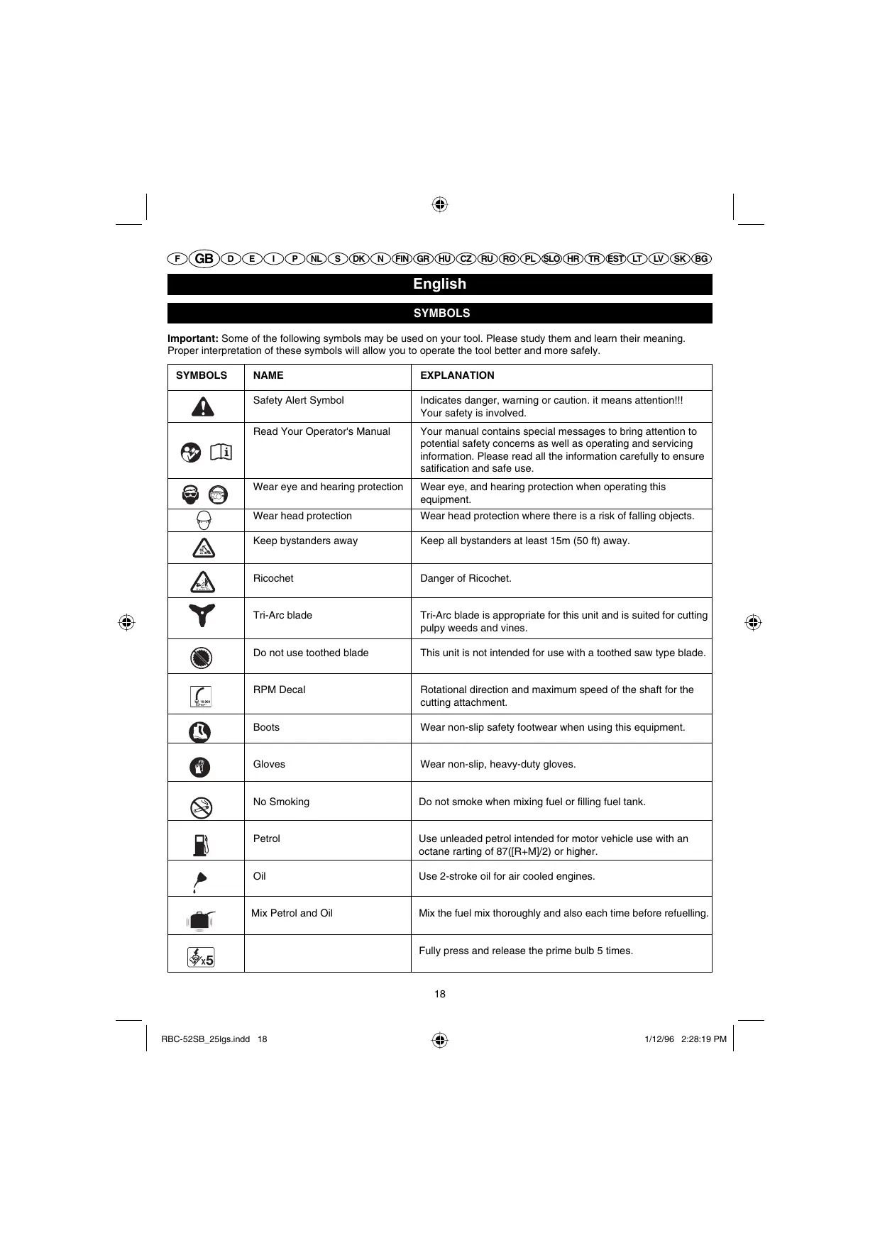
Important: Some of the following symbols may be used on your tool. Please study them and learn their meaning. Proper interpretation of these symbols will allow you to operate the tool better and more safely.
| SYMBOLS | NAME | EXPLANATION |
 | Safety Alert Symbol | Indicates danger, warning or caution. it means attention!!!Your safety is involved. |
  | Read Your Operator's Manual | Your manual contains special messages to bring attention to potential safety concerns as well as operating and servicing information. Please read all the information carefully to ensure satification and safe use. |
  | Wear eye and hearing protection | Wear eye, and hearing protection when operating this equipment. |
| [SBW8] | Wear head protection | Wear head protection where there is a risk of falling objects. |
 | Keep bystanders away | Keep all bystanders at least 15m (50 ft) away. |
 | Ricochet | Danger of Ricochet. |
 | Tri-Arc blade | Tri-Arc blade is appropriate for this unit and is suited for cutting pulpy weeds and vines. |
 | Do not use toothed blade | This unit is not intended for use with a toothed saw type blade. |
 | RPM Decal | Rotational direction and maximum speed of the shaft for the cutting attachment. |
 | Boots | Wear non-slip safety footwear when using this equipment. |
 | Gloves | Wear non-slip, heavy-duty gloves. |
 | No Smoking | Do not smoke when mixing fuel or filling fuel tank. |
 | Petrol | Use unleaded petrol intended for motor vehicle use with an octane rarting of 87([R+M]/2) or higher. |
 | Oil | Use 2-stroke oil for air cooled engines. |
| [DO3W] | Mix Petrol and Oil | Mix the fuel mix thoroughly and also each time before refuelling. |
| [SBWX] | Fully press and release the prime bulb 5 times. |
English
SYMBOLS
Important: Some of the following symbols may be used on your tool. Please study them and learn their meaning. Proper interpretation of these symbols will allow you to operate the tool better and more safely.
| SYMBOLS | NAME | EXPLANATION |
| CE | Conforms to all regulatory standards in the country in the EU where the product is purchased. |
Thank you for buying a Ryobi trimmer/brushcutter.
Your new trimmer/brushcutter has been engineered and manufactured to Ryobi's high standard for dependability, ease of operation, and operator safety. Properly cared for, it will give you years of rugged, trouble-free performance.

WARNING
To reduce the risk of injury, the user must read and understand the operator's manual.

WARNING
Do not attempt to operate this trimmer/brushcutter until you have read thoroughly and understood completely all instructions, safety rules etc contained in this manual. Failure to comply may result in accidents involving fire, electric shock or serious personal injury. Save operator's manual and review frequently for continuing safe operation, and instructing others who may use this tool.
READ ALL INSTRUCTIONS.
GENERAL SAFETY RULES
■ For safe operation, read and understand all instructions before using the trimmer/brushcutter. Follow all safety instructions. Failure to follow all safety instructions listed below, can result in serious personal injury.
■ Do not allow children or untrained individuals to use this unit.
■ Never start or run the engine in a closed or poorly ventilated area; breathing exhaust fumes can kill.
- Clear the work area before each use. Remove all objects such as rocks, broken glass, nails, wire, or string which can be thrown or become entangled in the string head or blade.
■ Wear full eye and hearing protection while operating this unit.
■ Wear heavy long pants, boots, and gloves. Do not
wear loose fitting clothing, short pants, jewellery of any kind, or use with bare feet.
- Secure long hair so it is above shoulder level to prevent entanglement in any moving parts.
- Keep all bystanders, children, and pets at least 15 m away.
■ Do not operate this unit when you are tired, ill, or under the influence of alcohol, drugs, or medication.
■ Do not operate in poor lighting.
- Keep firm footing and balance. Do not overreach. Overreaching can result in loss of balance or exposure to hot surfaces.
- Keep all parts of your body away from any moving part. - Do not touch area around the muffler or cylinder of the trimmer/brushcutter, these parts get hot from operation.
■ Always stop the engine and remove the spark plug wire before making any adjustments or repairs except for carburetor adjustments.
- Inspect the unit before each use for loose fasteners, fuel leaks, etc. Replace any damaged parts before use.
■ The string head or blade will rotate during carburetor adjustments.
It has been reported that vibrations from hand-held tools may contribute to a condition called Raynaud's Syndrome in certain individuals. Symptoms may include tingling, numbness and blanching of the fingers, usually apparent upon exposure to cold. Hereditary factors, exposure to cold and dampness, diet, smoking and work practices are all thought to contribute to the development of these symptoms. It is presently unknown what, if any, vibrations or extent of exposure may contribute to the condition. There are measures that can be taken by the operator to possibly reduce the effects of vibration:
a) Keep your body warm in cold weather. When opera-ting the unit wear gloves to keep the hands and wrists warm. It is reported that cold weather is a major factor contributing to Raynaud's Syndrome.
English
GENERAL SAFETY RULES
b) After each period of operation, exercise to increase blood circulation.
c) Take frequent work breaks. Limit the amount of exposure per day.
If you experience any of the symptoms of this condition, immediately discontinue use and see your physician about these symptoms.
- Keep the tool well maintained, fasteners tightened and worn parts replaced.
■ Mix and store fuel in a container approved for fuel. - Mix fuel outdoors where there are no sparks or flames. Wipe up any fuel spillage. Move 9 m away from refueling site before starting engine.
■ Stop the engine and allow to cool before refueling or storing the unit. - Allow the engine to cool; empty the fuel tank and secure the unit from moving before transporting in a vehicle.
SPECIFIC SAFETY RULES FOR TRIMMER USE
- Replace string head if cracked, chipped, or damaged in any way. Be sure the string head or blade is properly installed and securely fastened. Failure to do so can cause serious injury.
■ Make sure all guards, straps, deflectors and handles are properly and securely attached.
■ Use only the manufacturer's replacement line in the cutting head. Do not use any other cutting attachment.
■ Never operate unit without the grass deflector in place and in good condition. - Maintain a firm grip on both handles while trimming. Keep string head below waist level. Never cut with the string head located over 76 cm or more above the ground.
SPECIFIC SAFETY RULES FOR BRUSHCUTTER AND BLADE USE
■ After engine stops, keep rotating blade in heavy grass or pulpy weeks until it stops.
■ Do not operate the brushcutter unless the blade guard is firmly secured in place and in good condition.
■ Use heavy gloves while installing or removing blades.
■ Always stop the engine and remove the spark plug wire before attempting to remove any obstruction caught or jammed in the blade or before removing and installing the blade.
■ Do not attempt to touch or stop the blade when it is rotating.
■ A coasting blade can cause injury while it continues to spin after the engine is stopped or throttle trigger released. Maintain proper control until the blade has completely stopped rotating.
■ Replace any blade that has been damaged. Always make sure blade is installed correctly and securely fastened before each use. Failure to do so can cause serious injury.
■ Use only the manufacturer's replacement blade intended for use on this brushcutter. Do not use any other blade.
■ The blade is suited for cutting pulpy weeds and vines only. Do not use for any other purpose. Never use the blade to cut woody brush.
Exercise extreme caution when using the blade with this unit. Blade thrust is the reaction that may occur when the spinning blade contacts anything it cannot cut. This contact may cause the blade to stop for an instant, and suddenly “thrust” the unit away from the object that was hit. This reaction can be violent enough to cause the operator to lose control of the unit. Blade thrust can occur without warning if the blade snags, stalls, or binds. This is more likely to occur in areas where it is difficult to see the material being cut. For cutting ease and safety, approach the weeds being cut from the right to the left. In the event an unexpected object or woody stock is encountered, this could minimize the blade thrust reaction.
■ Never cut any material over 13 mm diameter.
■ Always wear the shoulder strap when using the brushcutter and adjust to a comfortable operating position. Maintain a firm grip on both handles while cutting with a blade. Keep the blade away from body and below waist. Never use the brushcutter with the blade located 76 cm or more above the ground level.
■ Cover the blade with the blade protector before storing the unit, or during transportation. Always remove the blade protector before using the unit. If not removed, the blade protector could become a thrown object as the blade begins to turn.
SPECIFICATIONS
Weight
- Without fuel, cutting attachment 7.52 kg
- With blade 7.87 kg
- With string head 7.72 kg
Fuel tank volume 1230 cm 4
Cutting swath 415 mm
English
SPECIFICATIONS
| Engine displacement | |
| RBC-52SB | 51.7 cm 3 |
| RBC-40SB | 40 cm 3 |
| Maximum engine performance(in accordance with ISO 8893) | |
| RBC-52SB | 1.4 kW / 1.9 HP |
| RBC-40SB | 1.27 kW / 1.7 HP |
| Maximum rotational frequencyof the spindle | 10000 min -1 |
| Engine speed (rotational frequency)at recommended max. spindlerotational frequency | 12500 min -1 |
| Engine speed (rotational frequency)at idle | 2250-2750 min -1 |
| Fuel consumption (in accordancewith ISO 8893) at max.engine performance | 0.85 kg/h |
| Specific fuel consumption(in accordance with ISO 8893)at max. engine performance | 0.45 kg/h |
| Vibration level idling | |
| - Left handle | 7.3 m/s 2 |
| - Right handle | 7.5 m/s 2 |
| Vibration level racing | |
| - Left handle | 7.2 m/s 2 |
| - Right handle | 7.5 m/s 2 |
| Sound pressure level(in accordance with EN ISO 11806:1997, ISO 7917:1987) | 102 LpA (dBA) |
| Sound power level(in accordance with ISO 10884) | 115 LwA (dBpA) |
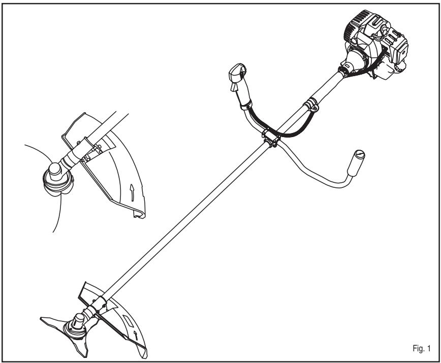
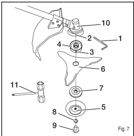
DESCRIPTION
- M6 wrench
- Hole of the gear case
- Hole in the upper flange washer
- Upper flange washer
- Blade cover
- Blade
- Cupped washer
- Washer
- Blade nut
- Gear case
- Spark plug wrench
- String head
- Connector
- Grass deflector
- Screw for grass deflector
- Locking tab
-
Notch
-
Handle bar
- Bottom clamp
- Shaft
- Throttle trigger
- Top clamp
- Latch
- Strap hanger
- Quick release tap
- Mounting bracket
- Best cutting area
- Dangerous cutting area
- Ignition switch
- Primer bulb
- Lever
- Blade protector
- Filter
ASSEMBLY
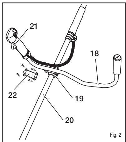
HANDLE (Fig. 2)
■ Place the handle bar (18) in the bottom clamp (19) located on the shaft (20) housing.
Note: The throttle trigger (21) must be mounted to the operator's right side.
■ Place the top clamp (22) on top and tighten the four M5 x 25 screws.
■ Adjust the handle bar for best operator control in a comfortable upright position.
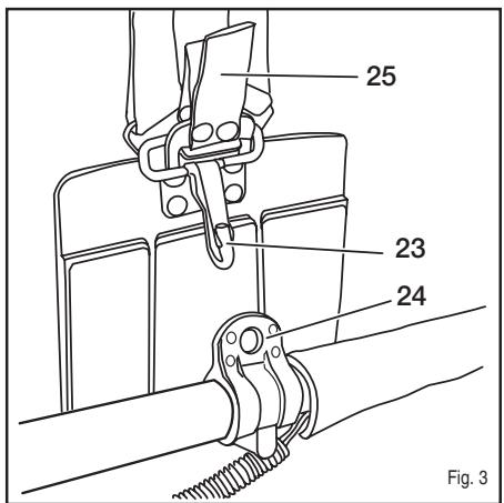
ATTACHING THE SHOULDER STRAP (Fig. 3)
■ Connect the latch (23) on the shoulder strap to the strap hanger (24).
■ Adjust the shoulder strap hanger to a balanced position where the blade or cutter attachment will suspend between 100 mm to 300 mm above the ground surface.
■ Adjust the strap hanger to a comfortable position.
Note: To quickly release the product from the shoulder strap, sharply pull the quick release tab (25).
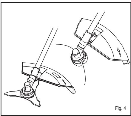
GRASS DEFLECTOR AND BLADE GUARD USE (Fig. 4)
Note: When converting from brushcutter to string trimmer or string trimmer to brushcutter, make sure the correct guard/deflector is being used.
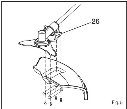
BLADE GUARD (Fig. 5)
■ Attach the blade guard to the mounting bracket (26); install the four screws (M5 x 16) from the bottom of the blade guard through the mounting plate and into the mounting bracket.
English
ASSEMBLY
■ Using the screwdriver supplied, tighten all four screws securely.
Note: When using the string head (12), the string shield must be attached to blade guard.
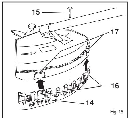
GRASS DEFLECTOR (Fig. 15)
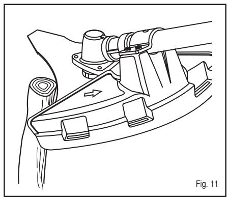
■ Attach the grass deflector (14) to the blade guard by placing the two locking tabs (16) into the two notches (17).
■ Using the screwdriver supplied, tighten the screw securely.

WARNING
Always stop the engine and remove the spark plug wire before making any adjustments such as changing cutting heads; this is to reduce the risk of serious personal injury.
CONVERTING FROM BRUSHCUTTER TO LINE TRIMMER
REMOVING THE BLADE (Fig. 7)
■ Place the M6 wrench (1) through the hole of the gear case (2) and the hole in the upper flange washer (3). Turn the blade nut (9) clockwise by using the larger end of the spark plug wrench (11) to remove.
■ Remove the washer (8), blade cover (5), cupped washer (7), blade (6) and upper flange washer (4). Retain the upper flange washer and cupped washer for string head installation.
■ Attach the grass deflector (14) to the blade guard by placing the 2 locking tabs into the two notches and tighten the grass deflector screw by the screw driver on the spark plug wrench.
NOTE: Store the brushcutter parts together for later use.
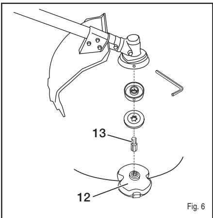
INSTALLING THE STRING HEAD (Fig. 6)
■ Place the upper flange washer over the gear shaft with the hollow side toward the gear head.
■ Install the cupped washer with the raised center away from the upper flange washer.
■ Place the M6 wrench through the hole of the gear case and the hole in the upper flange washer. Install the smaller end of the connector (13) to the gear head by turning counterclockwise. Tighten securely.
■ With the M6 wrench in place, turn the string head (12) counterclockwise onto the larger end of the connector to install. Tighten securely.
CONVERTING FROM LINE TRIMMER TO BRUSHCUTTER
REMOVING THE STRING HEAD (Fig. 6)
■ Place the M6 wrench through the hole of the gear case and the hole in the upper flange washer. Remove the string head by turning clockwise.
■ With the M6 wrench in place, turn the connector clockwise to remove.
■ Remove the cupped washer and upper flange washer. Retain them for blade installation.
■ Loosen the screw on the grass deflector. Remove the grass deflector by pushing in on the two locking tabs while pulling on the grass deflector to separate from the blade guard.
NOTE: Store the string head and grass deflector parts together for later use.
INSTALLING THE BLADE (Fig. 7)
■ Place the upper flange washer over the gear shaft with the hollow side toward the gear head.
■ Center the blade on the upper flange, making sure the blade sits flat. Install the cupped washer with the raised center away from the blade.
■ Place the blade cover and washer on top.
- Install the blade nut by turning counterclockwise. Place the M6 wrench through the hole of the gear case and the hole in the upper flange washer. Tighten the blade nut securely with the larger end of the spark plug wrench.
OPERATION

Read the operation manual and follow all warnings and safety instructions.

Wear eye protection and ear protection.

Keep all bystanders, especially children and pets, at least 15 m from the operating area.
FUEL AND REFUELING
HANDLING THE FUEL SAFELY
■ Always handle fuel with care, it is highly flammable.
■ Always refuel outdoors where there are no sparks and flames. Do not inhale fuel vapors.
■ Do not let petrol or oil come in contact with your skin.
- Keep petrol and oil away from the eyes. If petrol or oil comes in contact with the eyes, wash them immediately with clean water. If irritation is still present, see a doctor immediately.
English
OPERATION
■ Clean up spilled petrol immediately.
MIXING THE FUEL
■ This product is powered by a 2-stroke engine and requires pre-mixing petrol and 2-stroke oil. Pre-mix unleaded petrol and 2-stroke engine oil in a clean container approved for petrol.
This engine is certified to operate on unleaded petrol intended for automotive use with an octane rating of 87 ([R + M] / 2) or higher.
■ Do not use any type of pre-mixed petrol / oil from fuel service stations, this includes the pre-mixed petrol / oil intended for use in mopeds, motorcycles, etc.
■ Use synthetic 2-stroke oil only. Do not use automotive oil or 2-stroke outboard oil.
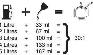
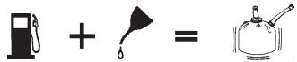
■ Mix the 2-stroke oil into the petrol. This is a 30:1 ratio.
■ Mix the fuel thoroughly and also each time before fueling.
■ Mix in small quantities. Do not mix quantities larger than usable in a 30 day period. Synthetic 2-stroke oil containing a fuel stabilizer is recommended.

FILLING THE TANK
■ Clean surface around fuel cap to prevent contamination.
■ Loosen fuel cap slowly to release pressure and to keep fuel from escaping around the cap.
■ Carefully pour fuel mixture into the tank. Avoid spillage.
■ Prior to replacing the fuel cap, clean and inspect the gasket.
- Immediately replace fuel cap and hand tighten. Wipe up any fuel spillage. Move 9 m away from refueling site before starting engine.
Note: It is normal for smoke to be emitted from a new engine during and after first use.

WARNING
Always shut off engine before fueling. Never add fuel to a machine with a running or hot engine. Move at least 9 m from refueling site before starting engine. Do not smoke!
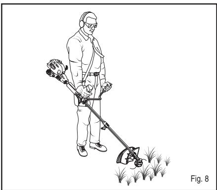
OPERATING THE TRIMMER (Fig. 8)
Hold the trimmer with the right hand on the trigger handle and the left hand on the left handle. Keep a firm grip with both hands while in operation. Trimmer should be held at a comfortable position with the trigger handle about hip height.
Always operate trimmer at full throttle. Cut tall grass from the top down. This will prevent grass from wrapping around the shaft housing and string head which may cause damage from overheating. If grass becomes wrapped around the string head, stop the engine, disconnect the spark plug wire, and remove the grass. Prolonged cutting at partial throttle will result in oil dripping from the muffler.
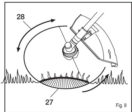
CUTTING TIPS (Fig. 9)
- Keep the trimmer tilted towards the area being cut; this is the best cutting area (27).
■ Do not cut in dangerous cutting area (28).
■ Use the tip of string to do the cutting; do not force string head into uncut grass.
■ Wire and picket fences cause extra string wear, even breakage. Stone and brick walls, kerbs and wood may wear string rapidly. - Avoid trees and shrubs. Tree bark, wood mouldings, cladding and fence posts can easily be damaged by the string.
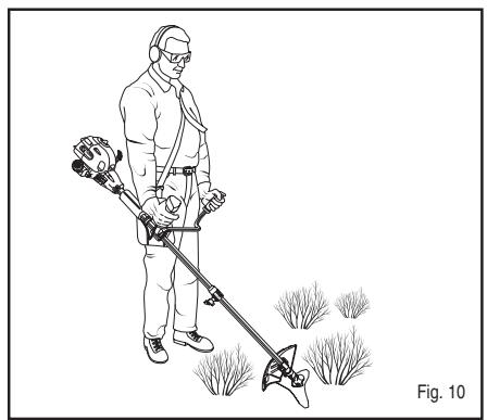
Hold the brushcutter with the right hand on the trigger handle and the left hand on the left handle. Keep a firm grip with both hands while in operation. Brushcutter should be held at a comfortable position with the trigger handle about hip height. Maintain your grip and balance on both feet. Position yourself so that you will not be drawn off balance by the kick-back reaction of the cutting blade.
Adjust the shoulder strap to position the brushcutter at a comfortable operating position and to assure that the shoulder strap will reduce the risk of operator contact with the blade.
Exercise extreme caution when using the blade with this unit.
English
OPERATION
Blade thrust is the reaction which may occur when the spinning blade contacts anything it cannot cut. This contact may cause the blade to stop for an instant, and suddenly “thrust” the unit away from the object that was hit. This reaction can be violent enough to cause the operator to lose control of the unit. Blade thrust may occur without warning if the blade snags, stalls or binds. This is more likely to occur in areas where it is difficult to see the material being cut. For cutting ease and safety, approach the weeds being cut from the right to the left. In the event that an unexpected object or woody stock is encountered, this could minimise the blade thrust reaction.
BLADE
The blade is suited only for pulpy weeds and vines. When the blade becomes dull, it can be turned over to extend the life of the blade. Do not sharpen the blade.
CUTTING TECHNIQUE - BLADE

WARNING
Extreme care must be taken when using blades to ensure safe operation. Read the safety information for safe operation using the blade, refer to “Specific Safety Rules for Brushcutter and Blade Use” earlier in this manual.
■ Always hold brushcutter with both hands when operating. Use a firm grip on both handles.
- Maintain your grip and balance on both feet. Position yourself so that you will not be drawn off balance by the kick-back reaction of the cutting blade.
■ Inspect and clear the area of any hidden objects such as glass, stones, concrete, fencing, wire, wood, metal, etc.
■ Never use blades near footpaths, fencing, posts, buildings or other immovable objects.
■ Never use a blade after hitting a hard object without first inspecting it for damage. Do not use if any damage is detected.
■ The unit is used as a scythe, cutting from the right to the left in a broad sweeping action from side to side.
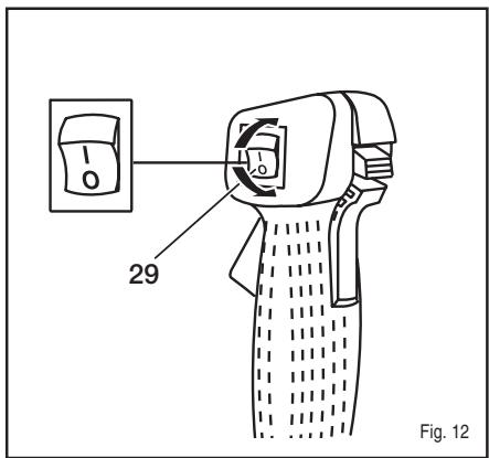
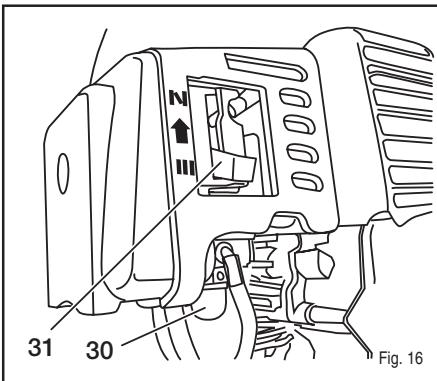
STARTING AND STOPPING (Fig. 12 and Fig. 16)

WARNING
Never start or run the engine inside a closed or poorly ventilated area; breathing exhaust fumes can kill.
TO START A COLD ENGINE:
- Lay trimmer on a flat, bare surface. Move ignition switch to the "1" position.
■ Push primer bulb (30) 5 times.
Note: Do not squeeze the throttle trigger (21) before engine starts. Squeezing the throttle trigger at this time will prevent the unit from starting.
■ Move the lever (31) up to close choke (|N|).
■ Pull the starter grip until engine starts.
■ Move the lever down to open choke (III). - Allow the engine to warm up for a few minutes before using.
TO START A WARM ENGINE:
- Lay trimmer on a flat, bare surface. Move ignition switch to the "l" position.
■ Choke lever should already be in the open choke (III) position. Pull the starter rope until unit runs.
TO STOP THE ENGINE:
To stop the engine, depress the ignition switch to the "O" position.
MAINTENANCE

WARNING
Use only original manufacturer's replacement parts, accessories and attachments. Failure to do so can cause possible injury, poor performance and may void your warranty.
■ The cutting attachment must not work in idle mode. If this requirement is not satisfied, the clutch has to be adjusted or the machine needs an urgent maintenance by a qualified technician.
■ You may make adjustments and repairs described here. For other repairs, have the trimmer serviced by an authorized service agent.
■ Consequences of improper maintenance may include excess carbon deposits resulting in loss of performance and discharge of black oily residue dripping from the muffler.
■ Make sure all guards, straps, deflectors and handles are properly and securely attached to avoid the risk of personal injury.
STRING REPLACEMENT
Use only 2.7mm diameter string.
■ Stop the engine, disconnect the spark plug wire.
English
MAINTENANCE
Hold the string head and unscrew from the unit. Turn clockwise.
■ Push the button on the string head and pull the string out.
■ Push the button and push the new line through the eyelet of the string head.
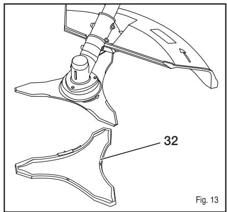
BLADE PROTECTOR (Fig. 13)
Always place the blade protector (32) on the blade when the unit is not in use. Wear gloves and be cautious when handling the blade.
Note: Always remove the blade protector before using the unit. If not removed, the blade protector could become a thrown object as the blade begins to turn.
CLEANING THE EXHAUST PORT AND MUFFLER
Depending on the type of fuel used, the type and amount of oil used, and/or your operating conditions, the exhaust port and muffler may become blocked with carbon deposits. If you notice a power loss with your petrol-powered tool, a qualified service technician will need to remove these deposits to restore performance.
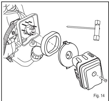
REPLACING AND CLEANING AIR FILTER (Fig. 14)
For proper performance and long life, keep air filter clean.
■ Remove the air filter cover by unscrewing the screw on the air filter cover.
■ Remove the holding plate in the air filter box.
■ Remove the filter (33), clean it in warm soapy water. Rinse and let dry completely. For best performance, replace annually.
■ Reinstall the filter.
■ Replace the holding plate.
■ Replace the air filter cover and tighten the screw.
FUEL CAP

WARNING
A leaking fuel cap is a fire hazard and must be replaced immediately.
The fuel cap contains a non-serviceable filter and a check valve. A clogged fuel filter will cause poor engine performance. If performance improves when the fuel cap is loosened, the check valve may be faulty or the filter clogged. Replace fuel cap if required.
SPARKING PLUG
This engine uses a TORCH L7RTC with 0.6 - 0.7mm electrode gap. Use an exact replacement and replace annually.
STORAGE (1 MONTH OR LONGER)
- Drain all fuel from tank into a container approved for petrol. Run engine until it stops.
■ Clean all foreign material from the trimmer. Store it in a well-ventilated place that is inaccessible to children. Keep away from corrosive agents such as garden chemicals and de-icing salts.
■ Cover the blade with the blade protector before storing the unit, or during transportation.
■ Abide by all ISO and local regulations for the safe storage and handling of petrol. Excess fuel should be used up in other 2-cycle engine-powered equipment.
English
TROUBLESHOOTING
IF THESE SOLUTIONS DO NOT SOLVE THE PROBLEM, CONTACT YOUR AUTHORISED SERVICE DEALER.
| PROBLEM | POSSIBLE CAUSE | SOLUTION |
| Engine will not start. | 1. No spark.2. No fuel.3. Flooded engine.4. Starter rope pulls harder now than when new. | 1. Check spark. Remove sparking plug. Reattach the sparking plug cap and lay sparking plug on metal cylinder. Pull the starter rope and watch for spark at sparking plug tip. If there is no spark, repeat test with new sparking plug.2. Push primer bulb until bulb is full of fuel. If bulb does not fill, primary fuel delivery system is blocked. Contact a service dealer. If primer bulb fills, engine may be flooded (see next item).3. Remove spark plug, turn trimmer so spark plug hole is aimed at the ground. Make sure lever is in the open choke (III) position and pull starter cord 10 to 14 times. This will clear excess fuel from engine. Clean and reinstall spark plug. With the throttle trigger fully depressed, pull starter cord three times with lever at open choke (III) position. If engine does not start, move choke lever to close choke (NJ) position and follow normal starting instructions in “STARTING AND STOPPING” section. If engine still fails to start, repeat procedure with a new spark plug.4. Contact a service dealer. |
| Engine starts but will not accelerate. | Carburetor requires adjustment. | Contact a service dealer. |
| Engine does not reach full speed and emits excessive smoke. | 1. Check oil fuel mixture.2. Air filter dirty.3. Carburetor requires adjustment. | 1. Use fresh fuel and the correct synthetic 2-stroke oil mix.2. Clean air filter. Refer to “Replacing and Cleaning Air Filter” earlier in this manual.3. Contact a servicing dealer. |
| Engine starts, runs, and accelerates but will not idle. | Carburetor requires adjustment | Contact a servicing dealer. |
| Blade continues to rotate at idle speed. | Carburetor requires adjustment. | Contact a servicing dealer. |
English
TROUBLESHOOTING
| PROBLEM | POSSIBLE CAUSE | SOLUTION |
| Grass wraps round shaft housing and string head. | 1. Cutting tall grass at ground level.2. Operating trimmer at part throttle. | 1. Cut tall grass from the top down.2. Operate trimmer at full throttle. |
| Oil drips from muffler. | 1. Operating trimmer at part throttle.2. Check oil/fuel mixture.3. Air filter dirty.4. Carburetor requires adjustment. | 1. Operate trimmer at full throttle.2. Use fresh fuel and the correct synthetic 2-stroke oil mix.3. Clean per instruction in Maintenance Section.4. Contact a servicing dealer. |
Deutsch
SYMBOLE
FÜLLEN DES TANKS
LLENAR EL DEPÓSITO
RIEMPIMENTO DEL SERBATOIO
Portugues
UTILIZAÇÃO
AFSCHERMKAP OF MESBESCHERMKAP MONTEREN (afb. 4)
MESBESCHERMKAP MONTEREN (afb. 5)
AFSCHERMKAP MONTEREN (afb. 15)
TANK BIJVULLEN
PÄFYLLNING I TANKEN
ANVÄNDNING AV GRÄSTRIMMERN (Fig. 8)
BRÆNDSTOF OG PÅFYLDNING AF BEHOLDER SIKKER HÅNDTERING AF BRÆNDSTOF
PÄFYLDNING AF BEHOLDER
DÆKSEL PÅ BRÆNDSTOFBEHOLDER

ADVARSEL
PÄFYLLING AV TANKEN
BRUK AV GRESSTRIMMEREN (Fig. 8)
RÅD FOR TRIMMING MED GRESSBLADET

ADVARSEL
SÄILIÖN TÄYTTÖ
A TARTÁLY FELTÖLTÉSE
PLNĚNÍ NÁDRŽE
POUŽÍVÁNÍ STRUNOVÉ SEKAČKY (obr. 8)
ЗАПРАВКА БАКА
CITIȚI TOATE INSTRUCTIUNILE.
MĂSURI DE SIGURANTĂ GENERALE
UMPLEREA REZERVORULUI
NAPEŁNIANIE ZBIORNKA
POLNJENJE POSODE ZA GORIVO
■ Očistite področje okoli pokrova posode za gorivo. Tako boste preprečili onesnaževanje.
■ Počasi odprite pokrov posode. Tako se bo sprostil tlak in gorivo ne bo onesnažilo pokrova.
■ Previdno napolnite mešanico goriva v posodo za gorivo. Preprečite razlitje. Preden ponovno namestite pokrov posode za gorivo, morate nujno očistiti in pregledati tesnilo.
Nato morate takoj namestiti pokrov posode za gorivo in ga zategniti z roko. Obrišite morebiti polito gorivo. Po dolivanju goriva se morate od mesta, kjer ste dolili gorivo, odmakniti za najmanj 9 metrov.
Opomba: Čisto običajen pojav je, da nov motor povzroča dim med in po prvi uporabi.

OPOZORILO
Pred dolivanjem goriva morate zmeraj ugasniti motor. Nikoli ne dolivajte goriva v motor, ki obratuje ali ki je še vroč. Po dolivanju goriva se morate od mesta, kjer ste dolili gorivo, odmakniti za najmanj 9 metrov. Ne kadite!
Slovensko
DELOVANJE
| 1 liter | + | 33 ml | = |
| 2 litra | + | 67 ml | = |
| 3 litri | + | 100 ml | = |
| 4 litri | + | 133 ml | = |
| 5 litrov | + | 167 ml | = |
UPORABA KOSILNICE (SI. 8)
PUNJENJE SPREMNIKA
■ Očistite spremnik oko čepa da se gorivo ni na koji način ne bi onečistilo.
■ Lagano odvijte čep spremnika da bi se olabavio tlak i da se gorivo ne bi razasulo oko čepa.
■ Sipajte mješavinu goriva u spremnik s oprezom, da se ne bi razlijevalo.
- Prije no što ponovno zavijete čep, očistite spoj i osigurajte se da je u dobrome stanju.
- Obrišite svaki trag goriva koje se eventualno izlilo. Udaljite se najmanje 9 m od mjesta gdje ste dopunjavali spremnik gorivom prije no što pokrenete motor.
Napomena: Normalno je da se iz motora ispušta dim tijekom prve uporabe, a ponekad i poslije toga.

UPOZORENJE
DEPO DOLDURMA
YAKIT DEPOSUNUN KAPAĞI

UYARI
HOIDKE NEED JUHISED ALLES!
ÜLDISED OHUTUSNÖUDED
PAAGI TÄITMINE
BAKO PRIPILDYMAS
| 1 litras | + | 33 ml | = |
| 2 litrai | + | 67 ml | = |
| 3 litrai | + | 100 ml | = |
| 4 litrai | + | 133 ml | = |
| 5 litrai | + | 167 ml | = |
ŽOLIAPJOVĖS NAUDOJIMAS (8 pav.)
IEPILDĪŠANA TVERTNĒ
Latviski
LIETOŠANA
PLNENIE NÁDRŽE
ЗАРЕЖДАНЕ НА РЕЗЕРВОАРА
GARANTIE - CONDITIONS
All Ryobi products are guaranteed against manufacturing defects and defective parts for a period of twenty four (24) months from the date stated on the original invoice drawn up by the retailer and given to the end user.
Deterioration caused by normal wear and tear, unauthorised or improper use or maintenance, or overload are excluded from this guarantee as are accessories such as battery packs, light bulbs, blades, fittings, bags, etc. In the event of malfunction during the warranty period, please take the NON-DISMANTLED product, along with the proof of purchase, to your retailer or nearest Authorised Ryobi Service Centre.
This warranty in no way affects your legal rights concerning defective products.

GARANTIE - BEDINGUNGEN
GARANTIJAS NOSACĪJUMI
DÉCLARATION DE CONFORMITÉ CE
CE DECLARATION OF CONFORMITY
We declare in sole responsibility that the product, to which this certificate applies, conforms to the basic health and safety requirements of the Machinery Directive 98/37/EC and other relevant directives, like EMC Directive 89/336/EEC and Outdoor Directive 2000/14/EC.
We declare this product complies to the requirements of the Outdoor Directive 2000/14/EC.
| Measured sound power level: | 110 dB (A) |
| Guaranteed sound power level: | 115 dB (A) |
| Date of issuance: | 12 / 2006 |
Technical documents are kept by Homelite Far East Co., Ltd. 24/F, 388 Castle Peak Road, Tsuen Wan, N. T., Hong Kong.
Declared in 12 / 2006 by Homelite Far East Co., Ltd.

Ryobi Technologies (UK) Limited.
MEDINA HOUSE, FIELD HOUSE LANE
MARLOW
BUCKS, SL7 1TB
UNITED KINGDOM
Tel: +44-1628 894 400 Fax: +44-1628 894 401
Name of company:
Address:





- IMPORTANT
- FRANÇAIS
- SYMBOLES
- UTILISATION
- REMLISSAGE DU RÉSERVOIR
- REPLACEMENT DU FIL (FIG. 18-21)
- ENGLISH
- SYMBOLS
- THANK YOU FOR BUYING A RYOBI TRIMMER/BRUSHCUTTER
- WARNING
- READ ALL INSTRUCTIONS
- GENERAL SAFETY RULES
- SPECIFIC SAFETY RULES FOR TRIMMER USE
- SPECIFIC SAFETY RULES FOR BRUSHCUTTER AND BLADE USE
- SPECIFICATIONS
- WEIGHT
- DESCRIPTION
- ASSEMBLY
- HANDLE (FIG. 2)
- ATTACHING THE SHOULDER STRAP (FIG. 3)
- GRASS DEFLECTOR AND BLADE GUARD USE (FIG. 4)
- BLADE GUARD (FIG. 5)
- GRASS DEFLECTOR (FIG. 15)
- CONVERTING FROM BRUSHCUTTER TO LINE TRIMMER
- REMOVING THE BLADE (FIG. 7)
- INSTALLING THE STRING HEAD (FIG. 6)
- CONVERTING FROM LINE TRIMMER TO BRUSHCUTTER
- REMOVING THE STRING HEAD (FIG. 6)
- INSTALLING THE BLADE (FIG. 7)
- OPERATION
- FUEL AND REFUELING
- HANDLING THE FUEL SAFELY
- MIXING THE FUEL
- FILLING THE TANK
- OPERATING THE TRIMMER (FIG. 8)
- CUTTING TIPS (FIG. 9)
- BLADE
- CUTTING TECHNIQUE - BLADE
- STARTING AND STOPPING (FIG. 12 AND FIG. 16)
- TO START A COLD ENGINE
- TO START A WARM ENGINE
- TO STOP THE ENGINE
- MAINTENANCE
- STRING REPLACEMENT
- BLADE PROTECTOR (FIG. 13)
- CLEANING THE EXHAUST PORT AND MUFFLER
- REPLACING AND CLEANING AIR FILTER (FIG. 14)
- FUEL CAP
- SPARKING PLUG
- STORAGE (1 MONTH OR LONGER)
- TROUBLESHOOTING
- DEUTSCH
- SYMBOLE
- FÜLLEN DES TANKS
- LLENAR EL DEPÓSITO
- RIEMPIMENTO DEL SERBATOIO
- PORTUGUES
- UTILIZAÇÃO
- AFSCHERMKAP OF MESBESCHERMKAP MONTEREN (AFB. 4)
- MESBESCHERMKAP MONTEREN (AFB. 5)
- AFSCHERMKAP MONTEREN (AFB. 15)
- TANK BIJVULLEN
- PÄFYLLNING I TANKEN
- ANVÄNDNING AV GRÄSTRIMMERN (FIG. 8)
- BRÆNDSTOF OG PÅFYLDNING AF BEHOLDER SIKKER HÅNDTERING AF BRÆNDSTOF
- PÄFYLDNING AF BEHOLDER
- DÆKSEL PÅ BRÆNDSTOFBEHOLDER
- ADVARSEL
- PÄFYLLING AV TANKEN
- BRUK AV GRESSTRIMMEREN (FIG. 8)
- RÅD FOR TRIMMING MED GRESSBLADET
- SÄILIÖN TÄYTTÖ
- A TARTÁLY FELTÖLTÉSE
- PLNĚNÍ NÁDRŽE
- POUŽÍVÁNÍ STRUNOVÉ SEKAČKY (OBR. 8)
- ЗАПРАВКА БАКА
- CITIȚI TOATE INSTRUCTIUNILE
- MĂSURI DE SIGURANTĂ GENERALE
- UMPLEREA REZERVORULUI
- NAPEŁNIANIE ZBIORNKA
- POLNJENJE POSODE ZA GORIVO
- OPOZORILO
- SLOVENSKO
- DELOVANJE
- UPORABA KOSILNICE (SI. 8)
- PUNJENJE SPREMNIKA
- UPOZORENJE
- DEPO DOLDURMA
- YAKIT DEPOSUNUN KAPAĞI
- UYARI
- HOIDKE NEED JUHISED ALLES
- ÜLDISED OHUTUSNÖUDED
- PAAGI TÄITMINE
- BAKO PRIPILDYMAS
- ŽOLIAPJOVĖS NAUDOJIMAS (8 PAV.)
- IEPILDĪŠANA TVERTNĒ
- LATVISKI
- LIETOŠANA
- PLNENIE NÁDRŽE
- ЗАРЕЖДАНЕ НА РЕЗЕРВОАРА
- GARANTIE - CONDITIONS
- GARANTIE - BEDINGUNGEN
- GARANTIJAS NOSACĪJUMI
- DÉCLARATION DE CONFORMITÉ CE
- CE DECLARATION OF CONFORMITY
Brand : RYOBI
Model : RBC52FSB, RBC52SB
Category : Brush cutter