
45260 - Paint spray Airpress - Free user manual and instructions
Find the device manual for free 45260 Airpress in PDF.

| Brand | Airpress |
| Model | 45260 |
| Type | Textured coating spray gun (paint spray) |
| Category | Paint spray |
| Recommended operating pressure | 3.5 to 4 bar |
| Maximum pressure | 4.5 bar |
| Included nozzles | 3 interchangeable nozzles: 4 mm, 6 mm, 8 mm |
| Hopper capacity | Approximately 5.5 liters |
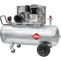
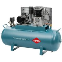
| Power supply | Compressed air (via compressor) |
| Air inlet connection | Quick connector (not specified) |
| Recommended spraying distance | 10 to 20 cm |
| Main material | Metal body, rubber seals |
| Use | Application of plaster, textured coatings |
| Safety | Do not point at people, wear PPE (eyes, hearing) |
| Maintenance | Cleaning with solvent; hopper can be immersed for max 24 hours |
| Spare parts available | Yes (detailed parts list with numbers) |
| Estimated weight | Approximately 2.5 kg |
| Warranty | Not specified |
Frequently Asked Questions - 45260 Airpress
User questions about 45260 Airpress
0 question about this device. Answer the ones you know or ask your own.
Ask a new question about this device
Download the instructions for your Paint spray in PDF format for free! Find your manual 45260 - Airpress and take your electronic device back in hand. On this page are published all the documents necessary for the use of your device. 45260 by Airpress.
USER MANUAL 45260 Airpress
natural_image
Close-up of a red spray gun with black handle and white plastic bulb, no visible text or symbolsPLASTER GUN
45260
EN | Preserve this handbook for future reference.
PL | Zachowaj ten podręcznik na przyszłość.
FR | Conserver le présent manuel pour pouvoir le consulter ultérieurement.
NL | Bewaar deze handleiding voor toekomstige raadpleging.
DE | Diese Bedienungsanleitung für späteres Nachschlagen sorgfältig aufbewahren.
HU | Tartsa meg ezt a használati útmutalót a későbbi használatra.
RO | Pästrați acest manual pentru consultări ultericare.
SK | Uschovajte si tuto priručku pre budúce použitie.
SI | Shrani to priročnik za kasnejšo referenco.
LV | Uzglabājiet śo lietośanas parnācību turpmākai lietośanai.
LT | Saugokte ši naudojimo vadovą, kad galėtumėte juo naudotis ateityje.
HR | Sačuvajte ovaj priručnik s uputama za buduću upotrebu.
CZ | Uschovejte tuto příručku pro budoucí potřebu.
EE | Hoida käesolev kasutusjuhend edaspidiseks kasutamiseks alles.
IT | Conservare il presente manuale di istruzioni per future consultazioni.
PT | Guarde este manual de instruções para referência futura.
ES | Guarde el manual para futuras consultas.
UA | Зберігайте цю інструкцію для подальшого використання.
FI | Säilytä tärmä käyttöohje myöhempää käyttöä varten.
NO | Behold denne håndboken for fremtidig referanse.
MK | Зачувајте го овој прирачник за идни референци.
SQ | Ruajeni këtë manual për reference të ardhshme.
SR | Zadržite ovaj priručnik za buduće reference.
SV | Spara denna handbok för framtida referens.
DK | Behold denne vejledning til fremtidig reference.
EN KEY TO PRODUCT SAFETY SIGNS
PL LEGENDA ZNAKÓW OSTRZEGAWCZYCH NA WYROBACH
FR LÉGENDE DES PICTOGRAMMES DE SÉCURITÉ FIGURANT SUR LES PRODUITS
NL VERKLARING WAARSCHUWINGSSYMBOLLEN OP PRODUCTEN
Workplace hazards and personal protection
-
Personal protective equipment must be worn during work, especially eye and hearing protection.
-
Do not use tools in explosive atmospheres, e.g., in the presence of flammable liquids, gases, or dust.
-
The workstation must be well-lit and kept clean.
-
Do not modify the device in any way.
-
Do not use the device if it is damaged in any way.
-
Do not point the device at other people while it is in use. Compressed air and coating material may cause injury.
-
Do not exceed the maximum operating pressure.
-
Use only with compressed air.
-
Keep children away from the unit.
-
Read the operating instructions before use.
-
Always disconnect tool from air source before servicing.
-
The tool is not designed for use in an explosive atmosphere.
-
Ensure work area is adequately ventilated.
-
Be aware of the hose on the ground during operation.
-
Do not expose the tool to fire or heat, this may damage the tool.
-
Make sure the tool is correctly assembled before use.
-
Use the tool as intended.
Use
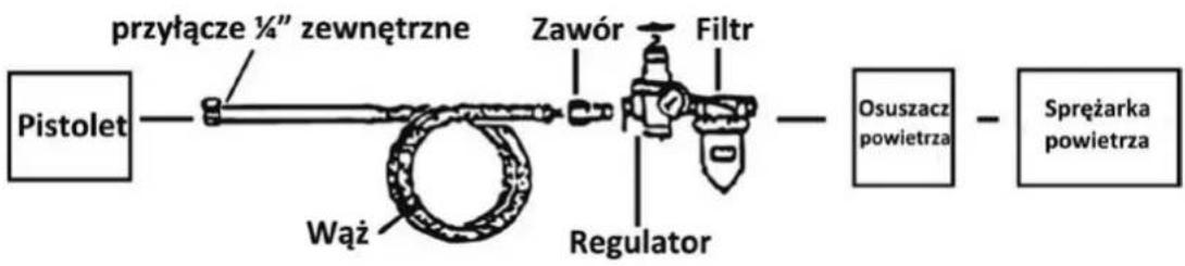
The diagram shows the recommended air installation components
Legend
The use of dry air with a plaster gun is recommended, so the use of an air dryer, a regulator, and an air filter is advised for optimum results. All components are available from Airpress distributors.
Note: It is advisable to test the gun on unneeded surfaces to familiarize yourself with its operation and capabilities.
- Place the gun body (#4) on the filler. Attach the gun body to the tank (#8) using the clamps (#6, #7).
Using a funnel (not included), add approximately 5.5 litres of plaster through the filler into the tank. -
Connect the hose to the air inlet connector (#19) and set the pressure at 3.5–4 bar. Do not exceed 4.5 bar.
-
Press the trigger (#23) to test the gun.
-
Use the gun at a distance of approx. 10–20 cm from the surface, holding the tool upright to the ground.
-
Keep your distance by moving the gun from side to side. Do not move it in an arc, or the plaster will be applied unevenly.
-
When you finish, release the trigger and disconnect the hose.
-
Empty the tank. Do not store it with plaster inside.
Adjustment
- You can adjust the flow of plaster using the adjustment knob (#18). Turn it slowly to adjust the pressure to your needs. You can also adjust the pressure at the compressor. Do not exceed 4.5 bar!
- You can change the nozzles (#2) for different effects. To do this, first disconnect the air source, then unscrew the tank ring (#1). Unscrew the nozzle from the gun and tighten the new one. Tighten the tank ring.
It is recommended to try all three nozzles before use.
Maintenance (cleaning)
The gun should be connected to the compressor to complete the cleaning process.
Caution: Do not use paint remover on the gun as it may damage it. Never lay the gun on its side while plaster is in the tank (#8).
- Remove the plaster from the tank (#8) and add a little solvent. Place the tank back and shake vigorously. On the lowest possible pressure, blow the solvent into the waste container (make sure you have a mask and safety goggles).
- Empty the tank of solvent and repeat the process until it is clean.
- Disconnect the air supply. Remove excess solvent and wipe the tank with a lint-free cloth.
Note: The tank can be fully immersed in solvent for up to 24 hours.
- Loosen the adjustment knob (#18) to expose the needle (#9). Use a brush with solvent to clean the needle. Replace the needle and tighten the adjustment knob. Do not tighten or insert any parts by force, as they may be damaged. Wipe the entire gun body (#4) with a lint-free cloth.
45260 PLASTER GUN
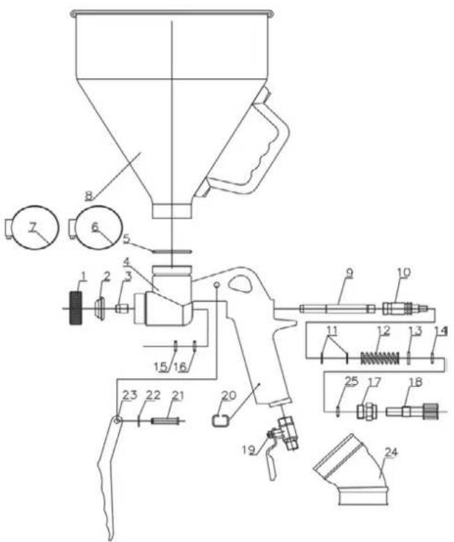
LIST OF PARTS
| Part | Description | Part # | Description |
| 1 | Tank ring | 14 | O-ring |
| 2 | Nozzle 4 mm / 6 mm / 8 mm | 15 | O-ring |
| 3 | Needle tip | 16 | O-ring |
| 4 | Gun body | 17 | Adjustment knob |
| 5 | O-ring | 18 | Adjustment knob |
| 6 | Clamp | 19 | Air inlet connector |
| 7 | Clamp | 20 | Clip ring |
| 8 | Tank | 21 | Drain plug |
| 9 | Needle | 22 | E-ring |
| 10 | Needle seat | 23 | Trigger |
| 11 | O-ring | 24 | 45° rubber link |
| 12 | Needle spring | 25 | O-ring |
| 13 | Seal |
LISTA CZĘŚCI
ERSATZTEILLISTE
ONDERDELENLIJST
LISTE DES PIÈCES
ALKATRÉSZJEGYZÉK
LISTA PIESELOR
ZOZNAM DIELOV
| Číslo | Popis | Číslo | Popis |
| 1 | Uzáver krúžku | 14 | O-krúžok |
| 2 | Tryska 4 mm / 6 mm / 8 mm | 15 | o-krúžok |
| 3 | Hrot ihly | 16 | o-krúžok |
| 4 | telo pištole | 17 | nastavovací gombík |
| 5 | o-krúžok | 18 | nastavovací gombík |
| 6 | Svorka | 19 | Konektor prívodu vzduchu |
| 7 | Svorka | 20 | upínací krúžok |
| 8 | Pohár | 21 | vypúštacia zátka |
| 9 | Ihla | 22 | E-krúžok |
| 10 | Sedlo ihly | 23 | Pištolová spúšť |
| 11 | O-krúžok | 24 | 45° gumová spojka |
| 12 | ihličková pružina | 25 | O-krúžok |
| 13 | tesnenie |
SEZNAM DELOV
SADALU SARAKSTS
DALYKŲ SĄRAŠAS
POPIS DIJELOVA
| Broj | Opis | Broj | Opis |
| 1 | Prsten za kapu | 14 | O-prsten |
| 2 | mlaznica 4 mm / 6 mm / 8 mm | 15 | O-prsten |
| 3 | vrh igle | 16 | O-prsten |
| 4 | tijelo pištolja | 17 | podešavanje gumba |
| 5 | O-prsten | 18 godina | gumb za podešavanje |
| 6 | Porok | 19 | priključak za usis zraka |
| 7 | Porok | 20 | prsten s kopčom |
| 8 | Krigla | 21 | okidač |
| 9 | Igla | 22 | E-prsten |
| 10 | utičnica za iglu | 23 | okidač pištolja |
| 11 | O-prsten | 24 | gumeni konektor od 45° |
| 12 | iglasta opruga | 25 | O-prsten |
| 13 | pečat |
SEZNAM DÍLŮ
OSALISTE LOETELU
ELENCO PARTI
LISTA DE PEÇAS
LISTA DE PIEZAS
ПЕРЕЛІК ДЕТАЛЕЙ
OSALUETTELO
DELELISTE
| Nummer | Beskrivelse | Nummer | Beskrivelse |
| 1 | Kappring | 14 | O-ring |
| 2 | dyse 4mm / 6mm / 8mm | 15 | o-ring |
| 3 | nålespiss | 16 | o-ring |
| 4 | pistolhus | 17 | justering av knott |
| 5 | O-ring | 18 | justeringsknott |
| 6 | Klemme | 19 | Luftinntakskontakt |
| 7 | Klemme | 20 | klipsring |
| 8 | Kopp | 21 | dreneringsplugg |
| 9 | Nål | 22 | E-ring |
| 10 | Nålens sete | 23 | pistolavtrekker |
| 11 | O-ring | 24 | 45° gummiledd |
| 12 | nålefjær | 25 | O-ring |
| 13 | tetning |
ЛИСТА НА ДЕЛОВИ
LISTA E PJESËVE
СПИСАК ДЕЛОВА
DELLISTA
DELELISTE
| Nummer | Beskrivelse | Nummer | Beskrivelse |
| 1 | Hættering | 14 | O-ring |
| 2 | Dyse 4mm / 6mm / 8mm | 15 | O-ring |
| 3 | Nålespids | 16 | O-ring |
| 4 | pistolhus | 17 | Knapjustering |
| 5 | O-ring | 18 | Justeringsknap |
| 6 | Klemme | 19 | Luftindtagsstik |
| 7 | Klemme | 20 | Klemmering |
| 8 | Kop | 21 | afløbsprop |
| 9 | Nål | 22 | E-ring |
| 10 | Nålens sæde | 23 | Pistoludløser |
| 11 | O-ring | 24 | 45° gummilink |
| 12 | nålefjeder | 25 | O-ring |
| 13 | Tætning |
LISTI YFIR HLUTI
| Hluti # | Lýsing | Hluti # | Lýsing |
| 1 | Tankurhringur | 14 | O-hringur |
| 2 | Stútur 4 mm / 6 mm / 8 mm | 15 | O-hringur |
| 3 | Nálbjórfé | 16 ára | O-hringur |
| 4 | Byssalíkami | 17 ára | Aðlögunhnappur |
| 5 | O-hringur | 18 ára | Aðlögunhnappur |
| 6 | Klemma | 19 ára | Loftinntakstengi |
| 7 | Klemma | 20 | Klippahringur |
| 8 | Tankur | 21 | Niðurfallstinga |
| 9 | Nál | 22 | E-hringur |
| 10 | Nálsæti | 23 ára | Kveikja |
| 11 | O-hringur | 24 | 45°gúmmítengi |
| 12 | Nálvor | 25 ára | O-hringur |
| 13 | Innsigli |
Geforen op der Aarbechtsplaz a perséinleche Schutz
LËSCHT VUN DEELER
| Deel # | Beschreibung | Deel # | Beschreibung |
| 1 | TankRank | 14 | O-Ring |
| 2 | Düse 4 mm / 6 mm / 8 mm | 15 | O-Ring |
| 3 | NolTipp | 16 | O-Ring |
| 4 | GewierKierper | 17 Joer | UpassungKnäpp |
| 5 | O-Ring | 18 Joer | UpassungKnäpp |
| 6 | Klemm | 19 Joer | LoftEntrée-Stecker |
| 7 | Klemm | 20 | KlipRank |
| 8 | Tank | 21 Joer | OflafStecker |
| 9 | Nol | 22 | E-Ring |
| 10 | NolSëtz | 23 Joer | Ausléiser |
| 11 | O-Ring | 24 Joer | 45°Gummi-Gelenk |
| 12 | NolFréijoer | 25 Joer | O-Ring |
| 13 | Siegel |
СПИС ЗАПЧАСТАК
СПИСЪК НА ЧАСТИТЕ
PARÇA LİSTESİ
Liosta na gCodanna

Brand : Airpress
Model : 45260
Category : Paint spray