
YT-06845 - Pneumatic brake bleeder Yato - Free user manual and instructions
Find the device manual for free YT-06845 Yato in PDF.

| Product type | Pneumatic brake bleeder |
| Brand | Yato |
| Model | YT-06845 |
| Maximum rated pressure | 0.27 MPa |
| Air connection diameter | 1/4" (6.3 mm) |
| Air hose inner diameter | 3/8" (10 mm) |
| Required air flow | 100 l/min (at 0.2 MPa) |
| Adapter hose length | 5 m |
| Reservoir capacity | 5 L |
| Weight | 9 kg |
| Sound level (acoustic pressure) | ≤ 70 dB(A) |
| Sound level (acoustic power) | ≤ 85 dB(A) |
| Vibration level | ≤ 2.5 m/s² |
| Power supply | Compressed air |
| Main functions | Brake fluid replacement and brake system bleeding |
| Maintenance | Drain the reservoir after use, clean with a soft cloth |
| Storage | Dark and dry place, out of reach of children |
| Recommended protective equipment | Safety goggles, gloves, protective clothing |
| Included adapters | Yes, for connection to the vehicle's brake system |
| Repairability | Entrust to a qualified professional |
Frequently Asked Questions - YT-06845 Yato
User questions about YT-06845 Yato
0 question about this device. Answer the ones you know or ask your own.
Ask a new question about this device
Download the instructions for your Pneumatic brake bleeder in PDF format for free! Find your manual YT-06845 - Yato and take your electronic device back in hand. On this page are published all the documents necessary for the use of your device. YT-06845 by Yato.
USER MANUAL YT-06845 Yato
natural_image
Exterior view of a YATO pressure relief device with coiled spring and pressure gauge (no text or symbols on main body)CE
PL EN DE RU UA LT LV CZ SK HU RO ES FR IT NL GR
natural_image
Black-and-white photo of a mechanical device with coiled tubing, a pressure regulator, and a bottle labeled '11' (no visible text or symbols on the device itself)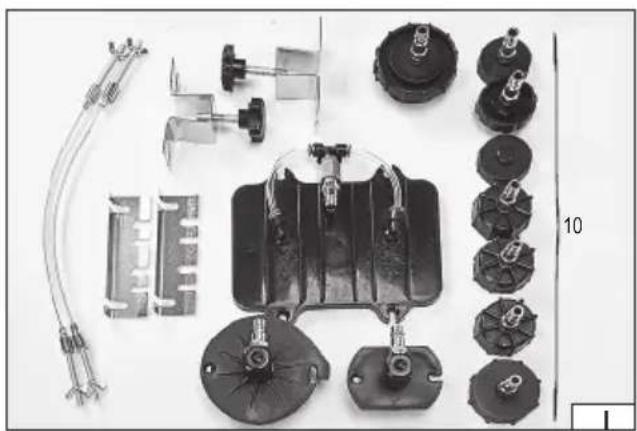
natural_image
Collection of automotive electrical components including motors, connectors, and wiring (no visible text or symbols)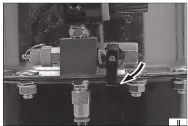
natural_image
Close-up of mechanical components with bolts and a directional arrow indicator (no readable text or symbols)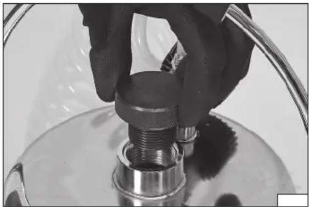
natural_image
Close-up of a hand adjusting a metallic pipe fitting with a coiled hose (no text or symbols visible)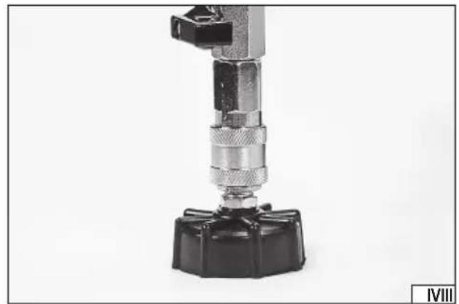
natural_image
Close-up of a mechanical clamp or connector with a black base and metallic fittings (no visible text or symbols)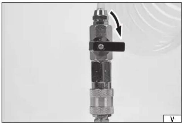
natural_image
Close-up of a mechanical coupling device with a black lever and arrow indicating rotation (no text or symbols visible)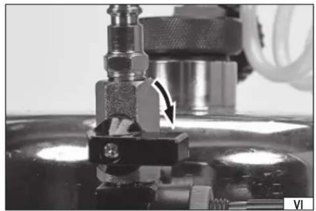
natural_image
Close-up of a mechanical component with a valve and tubing, no visible text or symbols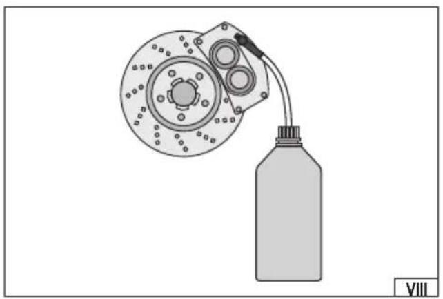
natural_image
Diagram of a mechanical device with a bottle connected to a circular housing and two cylindrical components (no text or symbols)
Read the operating instruction
Wear protective goggles
Schutzbrille tragen
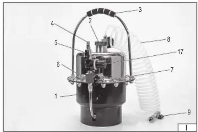
-
tank
-
brake fluid inlet
-
handle
-
air inlet
-
air inlet valve
-
safety valve
-
pressure relief valve
-
hose
-
hose valve
-
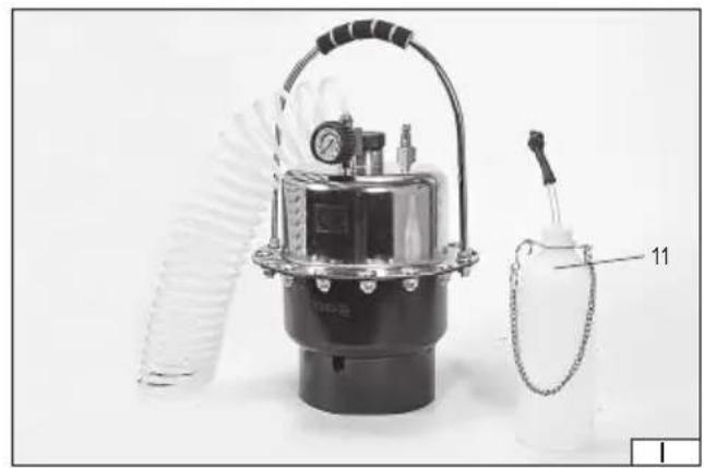
adapter
-
bottle
-
tool
-
hose socket
-
hose
-
hose connector
-
greaser
-
reducer
-
filter
-
compressor
DE
The device for brake fluid replacement significantly improves and speeds up the procedure for changing brake fluid in vehicles. It also makes it possible to remove the air stored in the brake system. Many different adapters allow the device to be used with most braking systems. Proper, reliable and safe operation of the device depends on appropriate use, that is why you should
Read and keep the entire manual before the first use of the device.
The tool supplier shall not be liable for any damage resulting from failure to comply the safety instructions and recommendations specified in this manual.
ACCESSORIES
The device is supplied with adapters for connection to the vehicle's braking system and with a tank for used brake fluid with a connection to the brake caliper. Before commencing work, some preparatory activities must be carried out, as described later in this manual.
TECHNICAL DATA
| Parameter Units Value | ||
| Catalogue No. YT-06845 | ||
| Maximum rated pressure [MPa] 0,27 | ||
| Diameter of air connector (PT) ["] / [mm] 1/4 / 6,3 | ||
| Diameter of air supply hose (internal) ["] / [mm] 3/8 / 10 | ||
| Required supply air flow (at 0,2 MPa) [l/min.] 100 | ||
| Adapter hose length | [m] | 5 |
| Fluid tank capacity | [l] | 5 |
| Weight | [kg] | 9 |
| Noise level | ||
| - sound pressure L_pA ± K_pA | [dB(A)] ≤ 70 | |
| - power L_wA ± K_wA | [dB(A)] ≤ 85 | |
| Vibration level _a0,AG ± K | [m/s] | ≤ 2,5 |
SAFETY INSTRUCTIONS
Please read and keep the entire manual before the first use of this device.
Warnings related to the operation of the device
Never exceed the maximum supply air pressure of the device.
Before commencing work on the vehicle's braking system, make sure that the engine is switched off and the vehicle is not moving. Apply the handbrake and place chocks under the wheels.
An efficient braking system determines the safe use of the vehicle, therefore it is required that the fluid change is carried out by personnel who are qualified and have been trained in the operation of the vehicle and the device.
Never point the outlet of the device towards people - brake fluid or compressed air can cause personal injury and other injuries. Injection of brake fluid can cause necrosis or even limb loss. In case of injection, immediately seek medical assistance.
Due to multiple hazards, read and understand the safety instructions before starting installation, operation, repair, maintenance and alteration of accessories or when working in the vicinity of a pneumatic device. Failure to do so may result in serious injury. Installation, adjustment and assembly of the pneumatic device may only be carried out by qualified and trained personnel. Do not modify the pneumatic device. Modifications can reduce efficiency and safety levels and increase operator risk. Do not throw the safety instructions away, they should be handed over to the operator of the device. Do not use the pneumatic device if it is damaged.
It is required that operators and maintenance personnel have received appropriate training in the use and repair of the device. It is forbidden to use any other gases instead of compressed air.
Use of other gases may result in serious injury, fire or explosion hazard.
When connecting the unit to the compressed air system, the space required for the hose must be taken into account in order to avoid damage to the hose or connectors.
The use of fluids other than the brake fluid is prohibited. Use of other fluids may cause damage to the vehicle.
Effective ventilation should be provided at the workstation. Lack of effective ventilation may cause health hazards, fire or explosion hazard.
This device is not intended for use in explosive environments.
Use the device keeping it away from heat sources and fire as this may damage the device or impair its operation.
Place the device on a level, hard and flat surface. Place the device vertically.
EN
Observe the general safety rules when working with sprayed materials, wear suitable personal protective equipment such as goggles, masks and gloves.
During operation or maintenance there is a risk of inhalation of brake or maintenance fluid particles caused by:
- insufficient natural or forced ventilation,
- improper atomising pressure,
- insufficient optimisation of spray parameters to reduce pollution,
- inhalation of solvent vapours or other hazardous substances,
- improper use, e.g. the use of the wrong fluid.
Never leave the assembled pneumatic system without the supervision by an authorised operator. Do not allow children near the assembled pneumatic system.
The high-pressure compressed air supply may cause the device to recoil in the opposite direction to the direction of brake fluid ejection. Special care should be taken as the forces of recoil may, under certain conditions, cause multiple injuries.
The device has a safety valve whose purpose is to prevent the accumulation of pressure in the device which is dangerous for the device. It is forbidden to modify the safety valve.
It is recommended to test the device before commencing work. It is recommended that the device operators are properly trained.
This will signifi cantly increase work safety.
Observe the brake fluid manufacturer's recommendations and use them in accordance with the specified personal, fire and environmental protection regulations. Not adhering to the brake fluid manufacturer's recommendations can lead to serious injuries. When operating with compressed air, energy is accumulated throughout the system. Care must be taken during operation and breaks between operation in order to avoid the risk of accumulated compressed air energy.
Due to the possibility of accumulation of electrostatic charges, measurements should be taken to ensure whether the device needs to be grounded and the use of surfaces and / or compressed air system dissipating electrical charges should be implemented. It is required that the measurements and assembly of such a system be carried out by qualified personnel.
Never direct the brake fluid flow to a heat or fire source, as this may cause fire.
Warnings related to brake fluid
Read and understand the vehicle's technical documentation for brake maintenance before replacing the brake fluid.
Brake fluid is a corrosive substance. Contact with human skin can cause irritation or even burns. Handle brake fluid with care and always wear eye protection, protective clothing, protective footwear and gloves.
Brake fluid in contact with clothing can damage, discolour or puncture it.
If the brake fluid comes into contact with the skin, rinse it with plenty of lukewarm running water and seek medical attention.
If brake fluid gets into the eyes, rinse them immediately with plenty of water and seek medical attention immediately.
Brake fluid in contact with the paint coating may cause damage to the coating. Care must be taken and paint coatings must be secured with special mats or covers.
In the event of spillage of brake fluid, the brake fluid should be immediately wiped.
Dispose of used brake fluid in accordance with the local regulations. Brake fluid poses a threat to the environment. It is forbidden to pour fluid into the sewage network, directly into water reservoirs or into the ground.
PRODUCT OPERATION
Preparing the device for operation
The product must be unpacked and all packaging components removed. Check the degree of tightness of the adapter hose to the device tank. Tighten if necessary. Tighten only with enough force to ensure tightness of the connection; tightening the hose nut too tightly can damage the seals.
Place the vehicle on stands and dismantle the wheels so as to gain access to the brake fluid system in the brake callipers. Vent the callipers in the order from the furthest to the nearest brake fluid reservoir.
Make sure that the pressure relief valve remains closed, the valve lever is perpendicular to the air connection (II).
Replacing brake fluid and venting the brake system
Fill the tank of the device with brake fluid. It is recommended to use a funnel or nozzle for filling to minimise the risk of spillage of brake fluid. Unscrew the tank lid (III). Fill the tank with brake fluid and then screw on the tank lid. Do not exceed the maximum tank capacity.
Warning! There is a flexible membrane in the reservoir that separates the brake fluid from the compressed air. If the air-lifted diaphragm does not drop by itself, open the pressure relief valve and unscrew the brake fluid filler cap. Insert a blunt object made of wood or plastic into the filler and push the diaphragm back to its original position. Do not use pointed objects to move the membrane. They can puncture the membrane which will cause irreparable damage to the product.
Remove the brake fluid tank lid of the vehicle and select the adapter most suited to the vehicle's brake fluid tank, then use it to replace the brake fluid tank lid. If such an adapter is not included with the device, a universal adapter should be fitted, secured by means of flexible cables covering the brake fluid tank. Connect the adapter to the hose (IV).
Close the hose valve, the valve lever is perpendicular to the air connection (V).
EN
Make sure the air valve is closed (VI), the valve lever is perpendicular to the air connection.
Connect the tool to the pneumatic system as shown in the Figure (VII) illustrating how to connect the device to the pneumatic system. The method shown will ensure the most efficient use of the device and will also extend the device life.
Adjust the system pressure so that it does not exceed the maximum permitted value. Adjustment should be made by means of an external reducer. The reducer in the device is used to adjust the pressure below the maximum value. Adjustment is made by pulling the knob of the reducer along the axis of rotation, and then rotating. Turning in the same direction as the arrow with the "+" symbol increases the pressure, and in the same direction as the arrow with the "-" symbol decreases the pressure. Once the pressure has been adjusted, the knob must be pressed along the axis of rotation to prevent accidental rotation which would result in an accidental change of pressure.
According to the vehicle documentation, open the vent in the calliper and connect the hose with the used brake fluid bottle (VIII) to it.
Open the valve at the device air inlet. Observe the hand of the device pressure gauge. Adjust the pressure so that it does not exceed the maximum value specified in the technical data table.
Slowly open the hose valve, fresh liquid will begin to flow out of the hose and at the same time the old liquid (darker colour) will flow out from the calliper into the bottle. Observe the fluid flow until the used fluid bottle fills up or the fluid flowing out of the calliper is lighter in colour and contains no air bubbles.
During fluid flow, press the brake pedal quickly and then slowly release the pressure. Repeat this cycle several times.
Caution! If you notice any leakage of fluid, e.g. at the connections, close the air inlet valve, the hose valve and check the cause of leakage, e.g. inaccurately latched connections, dirty connections, threaded connections which are not tightened.
After the fluid change, close the hose valve, then close the air valve, disconnect the bottle hose from the vent and close the vent. Repeat the procedure for the remaining brake callipers.
Close the hose valve on each brake calliper when fluid change is complete, then close the air inlet valve. Disconnect the device from the pneumatic system and then disconnect the hose from the brake fluid tank lid adapter. Replace the adapter with the brake fluid tank lid.
Replacing brake fluid and venting the ABS brake system
In the case of a braking system equipped with ABS, the whole procedure shall be carried out according to the above instructions with the following exceptions.
Put the vehicle into parking gear and have the engine running throughout the fluid change process. When the brake fluid has been replaced, stop the engine.
Preparation of the vehicle after fluid change
Prior to driving, press the brake pedal several times until it becomes hard. Check the brake callipers for leaks. Then test the brakes of the vehicle in a safe spot at low speed.
MAINTENANCE AND STORAGE
Caution! Before starting maintenance work, make sure that the hose valve and the air inlet valve are closed and that the device is disconnected from the pneumatic power supply and the adapter is disconnected from the device.
Caution! Before starting any maintenance-related work, release the pressure accumulated in the system and slowly turn the lever of the pressure relief valve. Whistle of air may be audible, wait several dozen seconds after it stops and then close the valve.
When the device finishes operation, the tank must be emptied of liquid, e.g. with a special pump or by tilting the tank and carefully pouring out the liquid through the inlet opening. Use a soft, dry cloth to clean the brake fluid residue.
Store the product in a tank without brake fluid. Store the product in a dark, dry place. The place of storage should prevent access to the product by unauthorised persons, especially children.
Provide adequate ventilation in the storage area so that water vapour does not condense, as it may corrode the product.
GERÄTEBESCHREIBUNG
CARACTÉRISTIQUES DU PRODUIT
MANIPULATION DU PRODUIT
DEKLARACJA ZGODNOŚCI DECLARATION OF CONFORMITY DECLARATIE DE CONFORMITATE
1124/YT-06845/EC/2024
We declare and guarantee with full responsibility that the following products:
meet requirements of the following European Standards / Technical Specifications:
and fulfill requirements of the following European Directives:
2006/42/EC Machinery and safety elements
Serial number: concern all serials numbers of item(s) mentioned in this declaration
The person authorized to compile the technical file: