
AP 300NV - Polisher Mirka - Free user manual and instructions
Find the device manual for free AP 300NV Mirka in PDF.

| Product Type | Pneumatic polisher |
| Brand | Mirka |
| Model | AP 300NV |
| Power Source | Compressed air |
| Maximum Air Pressure | 6.2 bar (90 psi) |
| Air Consumption | 626 l/min (22 scfm) |
| Free Speed | 3,200 rpm |
| Pad Diameter | 77 mm (3 in) |
| Net Weight | 0.66 kg (1.46 lb) |
| Dimensions (H x W) | 113.0 x 172.5 mm |
| Power | 298 W (0.40 HP) |
| Sound Level | 76.0 dBA |
| Vibration Level | 1.34 m/s² (uncertainty 0.63 m/s²) |
| Eccentricity | Not applicable |
| Compatible Materials | Metal, wood, stone, plastics |
| Required Protective Equipment | Safety glasses, respirator mask, gloves, hearing protection |
| Lubrication | Pneumatic motor oil (FK-20, ALMO 525, TORCULA 32) and molybdenum disulfide grease |
| Recommended Hose Diameter | 10 mm (3/8 in) |
| Maximum Hose Length | 8 m (25 ft) |
| Maintenance | Daily cleaning of dust bag, daily lubrication, cleaning of inlet filter |
| Safety | Do not exceed 6.2 bar, wear PPE, disconnect air before changing abrasive |
Frequently Asked Questions - AP 300NV Mirka
User questions about AP 300NV Mirka
0 question about this device. Answer the ones you know or ask your own.
Ask a new question about this device
Download the instructions for your Polisher in PDF format for free! Find your manual AP 300NV - Mirka and take your electronic device back in hand. On this page are published all the documents necessary for the use of your device. AP 300NV by Mirka.
USER MANUAL AP 300NV Mirka
natural_image
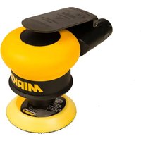
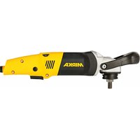
MIRKA air-pool push tool with black and white body (no visible text or symbols)
natural_image
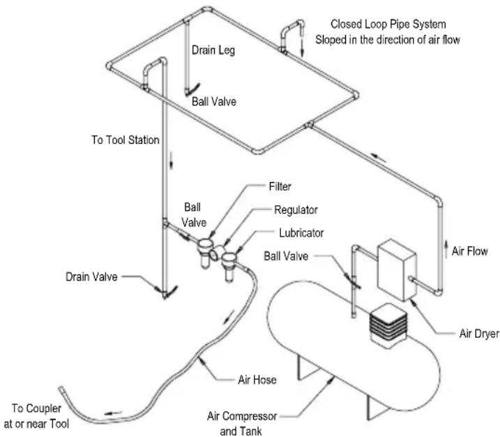
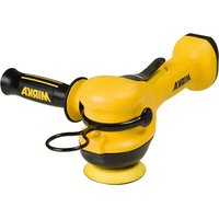
Stylized illustration of a bulldog in aggressive posture (no text or symbols)Mirka® Angle Polisher
77 mm (3")
ar 4-7
UK Operating instructions 124-124
Parts Page
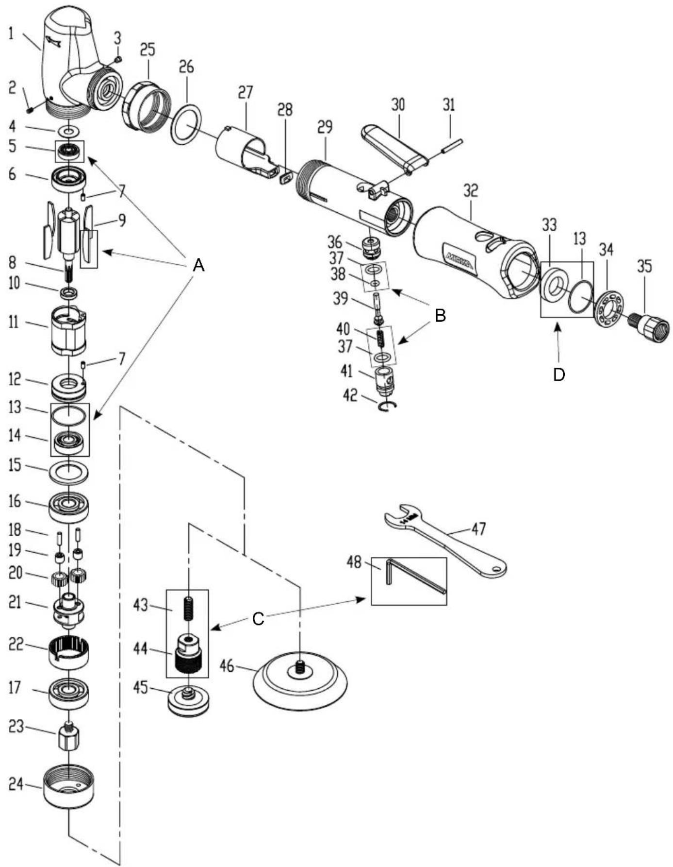
Parts List
| Item Description Qty. | |
| 1 MOTOR HOUSING 1 | |
| 2 SET SCREW 1 | |
| 3 OILER 1 | |
| 4 SHIELD 1 | |
| A BEARING AND VANES KIT | |
| 5 BEARING 1 | |
| 6 REAR END PLATE 1 | |
| 7 SPRING PIN 2 | |
| 8 ROTOR 1 | |
| A BEARING AND VANES KIT | |
| 9 VANES 4 | |
| 10 SPACER 1 | |
| 11 CYLINDER | 1 |
| 12 FRONT END PLATE | 1 |
| A BEARING AND VANES KIT | |
| 13 O-RING 1 | |
| 14 BEARING 1 | |
| 15 SPACER 1 | |
| 16 BEARING 1 | |
| 17 BEARING 1 | |
| 18 NEEDLE ROLLER 2 | |
| 19 NEEDLE BEARING | 2 |
| 20 PLANET GEAR | 2 |
| 21 PLANETARY CARRIER | 1 |
| 22 RING GEAR | 1 |
| 23 ADAPTER(1/4"-20) 1 | |
| 24 REAR EXHAUST COVER | 1 |
| 25 LOCK NUT | 1 |
| 26 GASKET 1 | |
| 27 AIR GUIDE | 1 |
| 28 GASKET 1 | |
| 29 THROTTLE HANDLE | 1 |
| 30 THROTTLE LEVER | 1 |
| 31 SPRING PIN | 1 |
| 32 GRIP | 1 |
| D MUFFLER AND O-RING KIT | |
| 33 MUFFLER FELT | 1 |
| 34 MUFFLER PLATE | 1 |
| 35 AIR INLET BUSHING | 1 |
| 36 THROTTLE VALVE | 1 |
| B O-RING AND VALVE SPRING KIT | |
| 37 O-RING 2 | |
| 38 O-RING 1 | |
| 39 VALVE STEM | 1 |
| B O-RING AND VALVE SPRING KIT | |
| 40 VALVE SPRING | 1 |
| 41 AIR REGULATOR | 1 |
| 42 SANP RING | 1 |
| C QUICK LOCK KIT | |
| 43 SET SCREW 1 | |
| 44 ADAPTER(1/4"-20) 1 | |
| 45 Backing Pad 77mm 1/4" | 1 |
| 46 Backing Pad Quick Lock 32mm | OPT |
| 47 14mm WRENCH | 1 |
| C QUICK LOCK KIT | |
| 48 L SHAPE HEX WRENCH(3.0mm) | 1 |
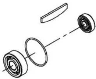
Spare Parts Kits
natural_image
Exploded view diagram of a mechanical assembly showing components like gears and a shaft (no text or labels)A AOS121 Bearing & Vanes Kit Code: 8992331211
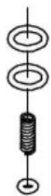
B AOS107 O-Ring & Valve Spring Kit
Code: 8992331071
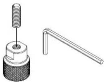
natural_image
Technical illustration of a mechanical component with threaded shaft and flanged lever (no text or symbols)C Quick Lock Kit Code: 8992324411
natural_image
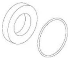
Two simple line drawings of concentric rings, no text or symbols presentD Muffler and O-Ring Kit Code: 8992321091
Broadway, New York, 1847; National Standards Institute, Inc
.1...1A New York
natural_image
Line drawing of a handheld electric shaver with a base mount (no text or symbols)natural_image
Line drawing of a handheld industrial device with a base and two cylindrical components (no text or symbols)natural_image
Line drawing of a mechanical device with a base and two accessories (no text or symbols)natural_image
Line drawing of a mechanical device with a base and two accessories (no text or symbols)Fejlsøgningsguide
https://osha.europa.eu/en (Europe)
http://www.osha.gov (USA)
Schmieranweisungen:
natural_image
Line drawing of a precision air purifier with attached sensor and base mount (no text or symbols)Fehlerbehebung
https://osha.europa.eu/en (Euρώπη)
http://www.osha.gov (НПА)
natural_image
Line drawing of a precision tool with a base and two accessories (no text or symbols)Declaration of conformity
Mirka Ltd.
Fl-66850 Jeppo, Finland
declare on our sole responsibility that the product
Mirka® AP 300NV 3,200 rpm Polisher (see "Product Configuration/Specifications" table for particular model)
to which this declaration relates is in conformity with the following standard(s) or other normative document(s) EN ISO 12100:2010, EN ISO 11148-
8:2011, EN ISO 15744:2008 & EN 28927-3:2009 in accordance with the regulation 2006/42/EC.
Jeppo 04.06.2020
MIRKA
Place and date of issue Company Stefan Sjöberg, CEO
Operator Instructions
Includes – Please Read and Comply, Proper Use of Tool, Work Stations, Putting the Tool Into Service, Operating Instructions, Product Configuration/Specifications Tables, Parts Page, Parts List, Trouble shooting guide.
Important
Read these instructions carefully before installing, operating, servicing or repairing this tool. Keep these instructions in a safe accessible location.

Manufacturer/Supplier
Mirka Ltd.
FI-66850 Jeppo
Finland
Tel: +358 20 760 2111


Required Personal Safety Equipment
Safety Glasses Breathing Masks
Safety Gloves Ear Protection
WARNING
Always wear required personal safety protection in accordance with manufacturer's instructions and local/national standards while using this tool.
- Do not use a power tool if you are tired or under the influence of drugs, alcohol or medication.
- Read the Materials Safety Data Sheet (MSDS) for the working surface.
- Use the tool with dust extraction. A suitable dust extraction unit will reduce hazardous dust.
- Do not overreach. Keep proper footing and balance at all times.
- Do not wear loose clothing or jewellery. Keep your hair, clothing and gloves away from moving parts.
Loose clothes, jewellery or long hair can be caught in moving parts. - If any physical hand/wrist discomfort is experienced, stop working and seek medical attention.
Hand, wrist and arm injury may result from repetitive work, motion and overexposure to vibrations. - Do not operate power tools in explosive atmospheres, such as in the presence of flammable liquids, gases or dust.
• The tool is not electrically insulated. Check work area for live electricity, gas pipes, etc. before operation.
CAUTION
- Prevent unintentional starting.
- Remove pad wrench before connecting the tool to the air supply.
- Keep work area clean and well lit.
• Always ensure that the work piece to be sanded is firmly fixed. - Before changing abrasive always disconnect the air supply.
Additional safety warnings
- Read all instructions before using this tool. All operators must be fully trained in usage and safety of this tool.
- All maintenance must be carried out by trained personnel. For service, contact Mirka authorized service centre!
• Always wear required safety equipment (see warnings). - The operator must be in a secure position and have a firm grip and footing on a solid floor.
• Always ensure that the work piece to be sanded is firmly fixed. - Check tool, backing pad, hose and fittings regularly for wear.
• Always take care to ensure your safety at work; never carry, store or leave the tool unattended with the air supply connected.
• Vacuum unit dust collection bag should be cleaned or replaced daily. Dust can be highly combustible.
Cleaning or replacing of bag also assures optimum performance. - Do not exceed maximum recommended air pressure of 6.2 bar (90 psi)
• Take care to avoid entanglement of the moving parts of the tool with clothing, ties, hair, cleaning rags, etc. - Keep hands clear of the spinning pad during use.
- If the tool appears to malfunction, remove from use immediately and arrange for service and repair.
- Before changing abrasive always disconnect the air supply. Take care to properly attach and centre the abrasive on the backing pad.
Please Read and Comply with
1) General Industry Safety & Health Regulations, Part 1910, OSHA 2206, available from: Superintendent of Documents; Government Printing Office; Washington DC 20402
2) Safety Code for Portable Air Tools, ANSI B186.1 available from: American National Standards Institute, Inc.; 1430 Broadway, New York, New York 10018.
3) State and Local Regulations.
Proper Use of Tool
This tool is designed for use on all types of materials i.e. metals, wood, stone, plastics, etc. using abrasive designed for this purpose. Do not use this tool for any other purpose than that specified without consulting the manufacturer or the manufacturer's authorized supplier. Do not use back-up pads that have a working speed less than 3,200 rpm free speed.
Work Stations
The tool is intended to be operated as a hand-held tool. It is always recommended that the tool be used when standing on a solid floor. It can be used in any position but before any such use, the operator must be in a secure position and have a firm grip and footing, and be aware that the tool can develop a torque reaction. See the section "Operating Instructions".
Putting the Tool into Service
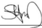
Use a clean lubricated air supply that will give a measured air pressure at the tool of 6.2 bar (90 psig) bar when the tool is running with the lever fully depressed. It is recommended to use an approved 10 mm (3/8 in.) x 8 m (25 ft) maximum length airline. It is recommended that the tool be connected to the air supply as shown in Figure 1.
Do not connect the tool to the airline system without incorporating an easy to reach and operate air shut-off valve. The air supply should be lubricated. It is strongly recommended that an air filter, regulator and lubricator (FRL) be used as shown in Figure 1 as this will supply clean, lubricated air at the correct pressure to the tool. Details of such equipment can be obtained from your supplier. If such equipment is not used then the tool should be manually lubricated.
To manually lubricate the tool, disconnect the airline and put 2 to 3 drops of suitable pneumatic motor lubricating oil such as Fuji Kosan FK-20, Mobil ALMO 525 or Shell TORCULA® 32 into the hose end (inlet) of the machine. Reconnect the tool to the air supply and run the tool slowly for a few seconds to allow air to circulate the oil. If the tool is used frequently, lubricate it on a daily basis or lubricate it if the tool starts to slow or lose power. It is recommended that the air pressure at the tool is 6.2 bar (90 psig) while the tool is running. The tool can run at lower pressures but never higher than 6.2 bar (90 psig).
Operating Instructions
1) Read all instructions before using this tool. All operators must be fully trained in its use and aware of these safety rules. All service and repair must be carried out by trained personnel.
2) Make sure the tool is disconnected from the air supply. Select a suitable abrasive and secure it to the back-up pad. Take care to center the abrasive on the back-up pad.
3) Always wear the required safety equipment when using this tool.
4) When sanding always place the tool on the work then start the tool. Always remove the tool from the work before stopping. This will prevent gouging of the work due to excess speed of the abrasive.
5) Always disconnect the air supply from the tool before fitting, adjusting or removing the abrasive or back-up pad.
6) Always adopt a firm footing and/or position and be aware of the torque reaction developed by the tool.
7) Use only correct spare parts.
8) Always ensure that the material to be sanded is firmly fixed to prevent its movement.
9) Check the hose and fittings regularly for wear. Do not carry the tool by its hose; always be careful to prevent the tool from being started when carrying the tool with the air supply connected.
10) Do not exceed the maximum recommended air pressure. Use safety equipment as recommended.
11) The tool is not electrically insulated. Do not use where there is a possibility of coming into contact with live electricity, gas pipes, water pipes, etc. Check the working area before operation.
12) Take care to avoid entanglement of the moving parts of the tool with clothing, ties, hair, cleaning rags, etc. If entangled, it will cause the body to be pulled towards the work and moving parts of the machine, which can be very dangerous.
13) Keep hands clear of the spinning pad during use.
14) If the tool appears to malfunction, remove from use immediately and arrange for service and repair.
15) Do not allow the tool to free speed without taking precautions to protect any persons or objects from the loss of the abrasive or pad.
flowchart
graph TD
    A["Air Dryer"] --> B["Regulator"]
    B --> C["Lubricator"]
    C --> D["Ball Valve"]
    D --> E["Filter"]
    E --> F["Regulator"]
    F --> G["Ball Valve"]
    G --> H["To Tool Station"]
    H --> I["Drain Leg"]
    I --> J["Ball Valve"]
    J --> K["To Coupler at or near Tool"]
    K --> L["Air Compressor and Tank"]
    L --> M["Air Hose"]
    M --> N["Air Air"]
    style A fill:#f9f,stroke:#333
    style N fill:#ccf,stroke:#333
Figure 1
Technical data
| Mirka® AP 300NV | |
| Recommended Airline Size - Minimum 10 mm 3/8 in | |
| Recommend Maximum Hose Length 8 meters 25 feet | |
| Air Pressure - Maximum Working Pressure 6.2 bar 90 psig | |
| Air Pressure - Recommended Minimum NA |
Product Configuration/Specifications: AP 300NV 3,200 rpm
| Orbit Pad Size mm (In.) | Model Number | Product Net Weight kg (pounds) | Height mm (inch) | Length mm (inch) | Power watts (HP) | Air Consumption LPM (scfm) | *Noise Level dBA | *Vibration Level m/s^2 | *Uncertainty K m/s^2 |
| NA | 77(3) | AP 300NV 0.66 (1.46) | 113.0(4.45) | 172.5(6.79) | 298 (0.40) 626 (22) 76.0 1.34 0.63 | ||||
| The noise test is carried out in accordance with EN ISO 15744:2008 – Hand-held non-electric power tools – Noise measurement code – Engineering method (grade 2) and EN ISO 11203:2009 Acoustics – Noise emitted by machinery and equipment – Determination of emission sound pressure levels at a work station and other specified positions from the sound power level.The vibration test is carried out in accordance with EN ISO 28927-3, Hand-held portable power tools – Test method for evaluation of vibration emission – Part 3: Polishers and rotary , orbital and random orbital sanders. | |||||||||
Specifications subject to change without prior notice.
*The values stated in the table are from laboratory testing in conformity with stated codes and standards and are not sufficient for risk evaluation. Values measured in a particular work place may be higher than the declared values. The actual exposure values and amount of risk or harm experienced to an individual is unique to each situation and depends upon the surrounding environment, the way in which the individual works, the particular material being worked, work station design as well as upon the exposure time and the physical condition of the user. Mirka, Ltd. cannot be held responsible for the consequences of using declared values instead of actual exposure values for any individual risk assessment.
Further occupational health and safety information can be obtained from the following websites: https://osha.europa.eu/en (Europe) http://www.osha.gov (USA)
Greasing Instructions:
Hold the tool in a horizontal position to keep the grease in the correct position. Lubricate with gear grease (molybdenum disulfide) using a suitable grease gun through the (3) Oiler with 2 to 3 plunges for 24 hours of use.
natural_image
Line drawing of a precision tool with a base and two other components (no text or symbols)Troubleshooting Guide
| Symptom Possible Cause Solution | ||
| Low power and/or low free speed. | Insufficient air pressure. Check air line pressure at the Inlet of the tool while the tool is running at free speed. It must be 6.2 bar (90 psig/620 kPa). | |
| Clogged Muffler(s). The Muffler can be back flushed with a clean, suitable cleaning solution until all contaminants and obstructions have been removed. If the Muffler can not be properly cleaned then replace it. Replace Muffler Insert. | ||
| Plugged Inlet Screen. Clean the Inlet Screen with a clean, suitable cleaning solution. If the Screen cannot be cleaned, replace it. | ||
| One or more worn or broken vanes. Install a complete set of new Vanes (all vanes must be replaced for proper operation). Coat all vanes with quality pneumatic tool oil. | ||
| Internal air leakage in the Motor Housing indicated by higher than normal air consumption and lower than normal speed. | Check for proper Motor alignment and Shield engagement. Check for damaged O-Ring in Front End Plate. Remove Motor Assembly and re-install the Motor Assembly. | |
| Motor parts worn. Overhaul Motor. Contact authorized Mirka Service Center. | ||
| Worn or broken Gear Bearings. Replace the worn or broken Gears and/or Bearings. | ||
| Air leakage through the Air Regulator and/or Valve Stem. | Dirty, broken or bent Valve Spring, Valve or O-Ring. | Disassemble, inspect and replace worn or damaged parts. |
| Vibration/rough operation. | Incorrect Pad. Only use Pad sizes and weights designed for the machine. | |
| Addition of interface pad or other material. Only use abrasives and/or interfaces designed for the machine. Do not attach anything to the Tool's Pad face that was not specifically designed to be used with the Pad and Tool. | ||
| Improper lubrication or buildup of foreign debris. | Disassemble the Tool and clean in a suitable cleaning solution. Reassemble the Tool. | |
| Worn or broken Rear or Front Motor Bearing(s). | Replace the worn or broken Bearings. | |
natural_image
Line drawing of a cleaning brush and tool assembly (no text or symbols)natural_image
Line drawing of a precision air purifier with attached sensor and base components (no text or symbols)Törkeotsing
https://osha.europa.eu/en (Europe)
http://www.osha.gov (USA)
Voiteluohjeet:
natural_image
Line drawing of a handheld electric shaver with a base mount and two accessories (no text or symbols)Vianetsintäohjeet
https://osha.europa.eu/en (Europe)
http://www.osha.gov (USA)
natural_image
Line drawing of a handheld electric shaver with a base, showing internal components and mounting base (no text or symbols)Guide de dépannage
natural_image
Line drawing of a precision tool with a base and two accessories (no text or symbols)natural_image
Line drawing of a handheld electric shaver with two accessories (no text or symbols)Azienda Stefan Sjöberg, CEO
natural_image
Line drawing of a handheld industrial tool with a base and two separate components (no text or symbols)natural_image
Line drawing of a mechanical device with a base and two accessories (no text or symbols)トラブルの原因と対策
1) 일반 산입 안진 보건 규정(General Industry Safety & Health Regulations, Part 1910, OSHA 2206, 자료 제공: Superintendent of Documents; Government Printing Office; Washington DC 20402).
2) 휴대용 에어 공구 안진 규정(Safety Code for Portable Air Tools, ANSI B186.1, 자료 제공: American National Standards Institute, Inc.; 1430 Broadway, New York, New York 10018).
3) 주/지방 법규.
올바른 공구 사용법
https://osha.europa.eu/en (유럽)
http://www.osha.gov (미국)
그리스 윤활 지침:
natural_image
Line drawing of a mechanical device with a base and two accessories (no text or symbols)문제 해결 가이드
natural_image
Line drawing of a mechanical device with a spherical base and two cylindrical components (no text or symbols)natural_image
Line drawing of a precision tool with a base, showing mechanical components and a cylindrical part (no text or symbols)https://osha.europa.eu/en (Europe)
http://www.osha.gov (USA)
natural_image
Line drawing of a mechanical device with a base and two components, no text or symbols presentFI-66850 Jeppo, Finland
natural_image
Line drawing of a mechanical device with a base and two accessories (no text or symbols)Problemen oplossen
natural_image
Line drawing of a portable electric shaver with attached sensor and base mount (no text or symbols)natural_image
Line drawing of a cleaning brush and tool assembly (no text or symbols)natural_image
Line drawing of a portable electric shaver with attached sensor and base mount (no text or symbols)natural_image
Line drawing of a precision tool with a base, showing mechanical components and a cylindrical part (no text or symbols)Ghid de depanare
natural_image
Line drawing of a mechanical device with a spherical base and two cylindrical components (no text or symbols)natural_image
Line drawing of a portable electric shaver with attached sensor and base mount (no text or symbols)natural_image
Line drawing of a precision tool with a base and two other components (no text or symbols)Vodič za otklanjanje problema
| Simptom Mogući uzrok Rešenje | ||
| Mala snaga i/ili mala brzina rotacije u slobodnom hodu. | Nedovoljan vazdušni pritisak. Proverite pritisak u vazdušnom vodu na ulazu alatke dok alatka radi bez opterećenja. Pritisak mora biti 6,2 bara (90 psig/620 kPa). | |
| Zapušeni prigušivači. Prigušivač je moguće | sprati čistim, odgovarajućim rastvorom za čišćenje dok se svi zagađivači i prljavština ne uklone. Ako prigušivač nije moguće pravilno očistiti, zamenite ga. Zamenite umetak za prigušivač. | |
| Zapušena mrežica na ulazu. Očistite ulaznu | mrežicu čistim, odgovarajućim rastvorom za čišćenje. Zamenite rešetku ukoliko je nije moguće očistiti. | |
| Jedna ili više lopatica je pohabano ili slomljeno. | Postavite ceo set novih lopatica (sve lopatice se moraju zameniti da bi se omogućio pravilan rad). Premažite sve lopatice kvalitetnim uljem za pneumatske alatke. | |
| Unutrašnje propuštanje vazduha u kućištu motora na koje ukazuje povećana potrošnja vazduha i smanjena brzina. | Proverite da li je motor centriran kako treba i da li štitnik dobro hvata. Proverite da li je oštećena prstenasta zaptivka u pločici na prednjem kraju. Skinite sklop motora, pa ga ponovo sastavite. | |
| Pohabani delovi motora. Remontujte motor. | Obratite se ovlašćenom servisu kompanije Mirka. | |
| Pohabani ili oštećeni ležajevi zupčanika. Zamenite pohabane ili oštećene zupčanike i/ili ležajeve. | ||
| Propuštanje vazduha kroz regulator vazduha i/ili telo ventila. | Prljava, oštećena ili iskrivljena opruga ventila, ventil ili prstenasta zaptivka. | Rastavite, pregledajte i zamenite pohabane ili oštećene delove. |
| Vibracije/grub rad. | Neodgovarajući podmetač. Koristite samo podmetače odgovarajuće veličine i težine za ovu mašinu. | |
| Dodavanje među-podmetača ili drugog materijala. | Koristite samo brusni papir i/ili umetke dizajnirane za ovu mašinu. Na površinu podmetača alatke nemojte stavljati ništa što nije namenski napravljeno da se koristi sa tim podmetačem ili alatkom. | |
| Neodgovarajuće podmazivanje ili nakupljanje naslaga stranih tela. | Rasklopite alatku i očistite je odgovarajućim rastvorom za čišćenje. Ponovo sklopite alatku. | |
| Pohabani ili oštećeni zadnji ili prednji ležajevi motora. | Zamenite pohabane ili oštećene ležajeve. | |
FI-66850 Jeppo, Finland
natural_image
Line drawing of a portable electric shaver with attached sensor and base mount (no text or symbols)Felsökningsguide
https://osha.europa.eu/en (Avrupa)
http://www.osha.gov (ABD)
natural_image
Line drawing of a portable electric shaver with attached sensor and base mount (no text or symbols)natural_image
Line drawing of a precision power tool with a base, showing its mechanical components and a separate cylindrical device (no text or symbols present)故障排除指南
Declaration of conformityMirka Ltd.FI-66850 Jeppo, Finlanddeclare on our sole responsibility that the productsMirka® AP 300NV 3,200 rpm Polisher (see “Product Configuration/Specifications” table for particular model) to which this declaration relates are in conformity with the following standard(s) or other normative document(s): BS EN ISO 12100:2010, BS EN ISO 11148-8:2011, BS EN ISO 15744:2008, and BS EN ISO 28927-3:2009 in accordance with the Supply of Machinery (Safety) Regulations 2008.Jeppo 14.07.2021   | |||
| Place and date of issue Company Stefan Sjöberg, CEO | |||
| Operator InstructionsIncludes – Parts Page, Parts List,Sander Spare Parts Kits, PleaseRead and Comply, Proper Use ofTool, Work Stations, Putting the ToolInto Service, Operating Instructions,Product Configuration/SpecificationsTables,Troubleshooting Guide. | ImportantRead these instruc-tions carefully beforeinstalling, operating,servicing or repairingthis tool. Keep theseinstructions in a safeaccessible location. | Importer InformationMirka (UK) LtdSaxon HouseShirwell CrescentFurzton LakeMilton KeynesMK4 1GATel. +44 (0)1908 866100 | UKCA |
| Manufacturer/SupplierMirka Ltd.FI-66850 Jeppo, FinlandTel: + 358 20 760 2111 | Required Personal Safety EquipmentSafety Glasses Breathing MasksSafety Gloves Ear Protection | ||
This chapter is an addition to the English language chapter of the manual in order to fulfill the UKCA regulation requirements. Please refer to the English language chapter for more information about your product.

geo
| Location | Marker | | -------- | ------ | | Mirka Ltd | 1 | | Finland | 2 | | Other global sites | 3 |Mirka Ltd
Finland
Brazil Mirka Brasil Ltda.
Belgium Mirka Belgium Logistics NV
Canada Mirka Canada Inc.
China Mirka Trading Shanghai Co., Ltd
Finland & Baltics Mirka Ltd
France Mirka France Sarl
Germany Mirka GmbH
India Mirka India Pvt Ltd
Russia Mirka Rus LLC
Singapore Mirka Asia Pacific Pte Ltd
Spain Mirka Ibérica S.A.U.
Sweden Mirka Scandinavia AB
Turkey Mirka Turkey Zimpara Ltd Şirketi
United Kingdom Mirka (UK) Ltd
United Arab Emirates Mirka Middle East FZCO
USA Mirka USA Inc.
For contact information,
please visit www.mirka.com
Dedicated to the finish
- Mirka® Angle Polisher
- Parts Page
- Spare Parts Kits
- Schmieranweisungen:
- Declaration of conformity
- Operator Instructions
- Important
- Manufacturer/Supplier
- Required Personal Safety Equipment
- WARNING
- CAUTION
- Additional safety warnings
- Please Read and Comply with
- Proper Use of Tool
- Work Stations
- Putting the Tool into Service
- Operating Instructions
- Greasing Instructions:
- Voiteluohjeet:
- 올바른 공구 사용법
Brand : Mirka
Model : AP 300NV
Category : Polisher