
Power+ WDV0300E - Vacuum Cleaner EGO - Free user manual and instructions
Find the device manual for free Power+ WDV0300E EGO in PDF.

| Product type | Cordless wet/dry vacuum |
| Brand | EGO |
| Model | Power+ WDV0300E |
| Rated voltage | 56 V DC |
| Tank capacity | 12 L |
| Weight (without battery) | 5.28 kg |
| Max air flow (ECO mode) | 1410 L/min |
| Max air flow (TURBO mode) | 2400 L/min |
| Max suction power (ECO mode) | 75 mBar |
| Max suction power (TURBO mode) | 150 mBar |
| Protection rating | IPX4 (splash resistant) |
| Battery type | Lithium-ion 56 V (compatible EGO models) |
| Operating temperature | -5 °C to 40 °C |
| Storage temperature | -20 °C to 70 °C |
| Speed modes | ECO and TURBO |
| Functions | Dry/wet vacuum, blower, filter self-cleaning |
| Remote control | Wireless with light, included |
| Included accessories | Hose, utility nozzle, flat nozzle with brush, power tool adapter, collection bag, filter, remote control, USB-C cable |
| Maintenance | Tank emptying, filter washing and replacement |
| Warranty | See terms on egopowerplus.eu |
Frequently Asked Questions - Power+ WDV0300E EGO
User questions about Power+ WDV0300E EGO
0 question about this device. Answer the ones you know or ask your own.
Ask a new question about this device
Download the instructions for your Vacuum Cleaner in PDF format for free! Find your manual Power+ WDV0300E - EGO and take your electronic device back in hand. On this page are published all the documents necessary for the use of your device. Power+ WDV0300E by EGO.
USER MANUAL Power+ WDV0300E EGO
EN 56 Volt lithium-ion cordless wet/dry vacuum
DE56Voltlithium-ionen-akku-nass-/trockensauger14
CH2100E, CH3200E, CH5500E, CH7000E, CH7000E-T
natural_image
Line drawing of a cylindrical electronic device with a button and mounting holes (no text or symbols)
natural_image
Line drawing of a portable electronic device with ventilation slots and a control panel (no text or symbols)B1
B3
natural_image
Diagram of a car engine plug with two lock icons and directional arrows indicating valve positions (no text or symbols present)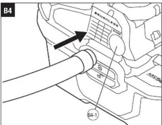
C1
C3
natural_image
Technical line drawing of a mechanical device with an arrow pointing to a component (no text or symbols present)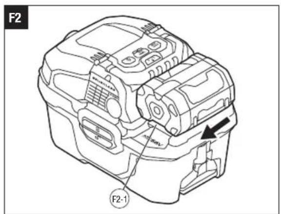

EGO Europe GmbH
The Anchorage, 34 Bridge Street Reading, RG1 2LU, United Kingdom
EN READ ALL INSTRUCTIONS!

READ OPERATOR'S MANUAL
WARNING: To ensure safety and reliability, all repairs should be performed by a qualified service technician.
SAFETY SYMBOLS
The purpose of safety symbols is to attract your attention to possible dangers. The safety symbols and the explanations with them deserve your careful attention and understanding. The symbol warnings do not, by themselves, eliminate any danger. The instructions and warnings they give are no substitutes for proper accident prevention measures.
WARNING: Be sure to read and understand all safety instructions in this Operator's Manual, including all safety alert symbols such as "DANGER," "WARNING," and "CAUTION" before using this machine. Failure to follow all instructions listed below may result in electric shock, fire, and/or serious personal injury.
SYMBOL MEANING
SAFETY ALERT SYMBOL: Indicates DANGER, WARNING, or CAUTION, may be used in conjunction with other symbols or pictographs.
SAFETY INSTRUCTIONS
This page depicts and describes safety symbols that may appear on this product. Read, understand, and follow all instructions on the machine before attempting to assemble and operate.

Safety Alert
CE This product is in accordance with applicable EC Directives.

To reduce the risk of injury, user must read the operator's manual.

UK Conformity Assessed

Waste electrical products should not be disposed of with household waste. Take to an authorized recycler.

Direct Current
L Litre IPX4 Protection from splashing water
°C Degrees Celsius kg Kilogram
V Voltage L/min Litre per minute
mBar Millibar

This product uses Li-ion batteries.
WARNING: Read and understand all instructions. Failure to follow all instructions listed below may result in electric shock, fire and/or serious personal injury.
This appliance is not intended for use by persons (including children) with reduced physical, sensory or mental capabilities, or lack of experience and knowledge, unless they have been given supervision or instruction concerning use of the appliance by a person responsible for their safety.
■ Children should be supervised to ensure that they do not play with the appliance.
■ Cleaning and user maintenance shall not be made by children without supervision.
■ Do not expose the appliance or battery to excessive temperatures.
■ Be aware of the risk of terminals of the battery-operated appliance or battery being short-circuited by metal objects.
■ Rechargeable batteries are to be removed from the appliance before being charged.
■ Different types of batteries or new and used batteries are not to be mixed.
■ Exhausted batteries are to be removed from the appliance and safely disposed of.
■ If the appliance is to be stored unused for a long period, the batteries should be removed.
■ Do not use non-rechargeable batteries in place of rechargeable batteries.
■ Do not use modified or damaged batteries.
■ Use only with the specified battery packs and chargers.
Save these instructions. Refer to them frequently and use them to instruct others who may use this machine. If you lend someone this machine, lend them these instructions also to prevent misuse of the product and possible injury.
SPECIFICATIONS
| Voltage | 56 V--- | |
| Collection tank Capacity 12 L | ||
| Speed Mode ECO TURBO | ||
| Max. Air Flow (L/min) 1410 2400 | ||
| Max. Suction Power (mBar) 75 150 | |||
| Remote Control | Charging Temperature | 0 °C - 45 °C | |
| Max. Charging Voltage | 5 V | ||
| Max. Charging Current | 1 A | ||
| Weight (without battery pack) 5.28 kg | |||
| Recommended Operating Temperature | -5 °C - 40 °C | ||
| Recommended Storage Temperature | -20°C - 70°C | ||
| Battery Charging Temperature 5°C - 40°C | |||
EN
PACKING LIST (FIG. A1)
RECOMMENDED ACCESSORIES
WARNING: Use only accessories listed below. Use of accessories that do not meet the original equipment specifications may lead to improper performance and compromised safety.
| PART NAME MODEL NUMBER | |
| Dust Bag AVG0305 | |
| Replacement Filter | AVF0300 |
DESCRIPTION
KNOW YOUR WET/DRY VACUUM (Fig. A1)
- Collection Tank Latch (x2)
- Blowing Outlet Port
- Handle
- Storage Compartment
- Filter Self-Cleaning Button
- Speed Adjustment Button
- Power Button
- Speed indicators
- Start/Stop Button
- Temporary Storage Port
- Utility Nozzle
- Battery-Release Button
EN
- Vacuum Hose
- Power-Tool Adapter
- Vacuum Hose End Storage / Filter Self-Cleaning Plug
- Storage Compartment Cover
- Vacuum Hose Storage Slot
- Crevice Nozzle
- Remote Control
- Suction Inlet Port
- Hose-Release Button
- Remote-Control Mount
- Dust Bag
- Charging Cable for Remote Control
- Power Head Assembly
- Filter
- Filter-Release Knob
- Collection Tank
- Dust Bag Bracket
ASSEMBLY
CONNECTING/DISCONNECTING THE VACUUM HOSE
To Connect/Disconnect with Suction Inlet Port
The vacuum hose may have been connected with the suction inlet port when shipped. In this case, check and ensure the end of the vacuum hose is secured in place.
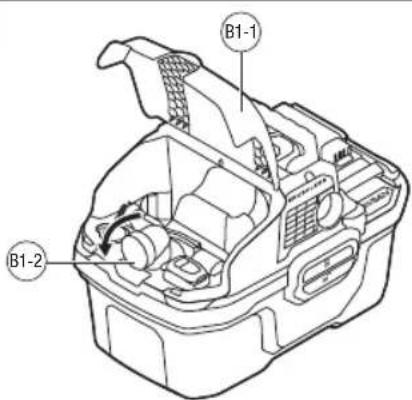
- Open the storage compartment cover and rotate the suction inlet port outward (Fig. B1).
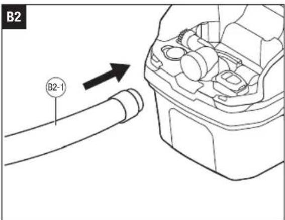
- Align the screw end of the hose with the suction inlet port (Fig. B2).
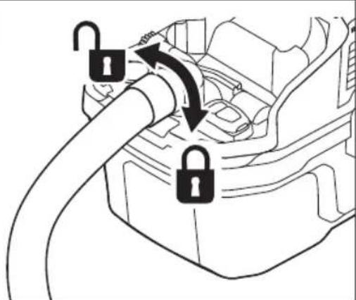
- Rotate the screw end of the hose into the suction inlet port clockwise and tighten until the end is secured in place (Fig. B3).
- To disconnect, rotate the screw end of the hose counterclockwise to loosen and remove the vacuum hose from the vacuum (Fig. B3).
Follow steps 2-4 to connect or disconnect the vacuum hose with the blowing outlet port (Fig. B4).
| B1-1 | Storage Compartment Cover | B1-2 Suction Inlet Port |
| B2-1 | Vacuum Hose B4-1 |
INSTALLING/REMOVING THE NOZZLES
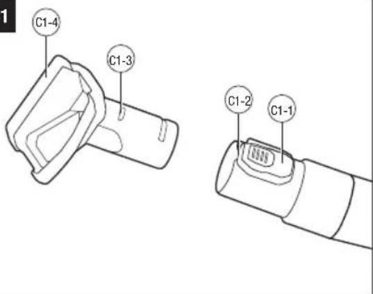
Utility Nozzle (Fig. C1)
- Align the peg on the nozzle with the groove in the vacuum hose, and then push the nozzle onto the vacuum hose until you hear a "click" sound which indicates the nozzle is installed in place.
- To disconnect, press and hold the hose-release button to remove the nozzle from the vacuum hose.
| C1-1 | Hose-Release Button C1-2 | Groove | |
| C1-3 | Peg C1-4 Utility Nozzle |
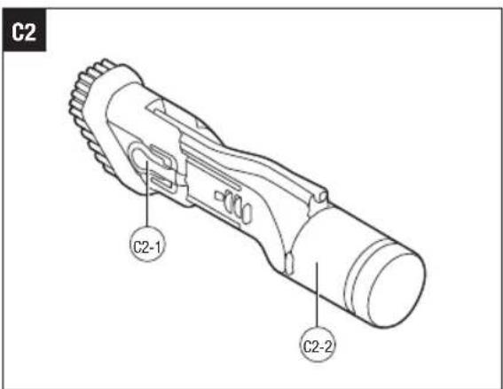
Crevice Nozzle
The crevice nozzle is equipped with a brush for additional cleaning. Press the brush-release button and push the brush forward until it is locked in place (Fig. C2). When the brush is no longer needed, press the brush-release button and push the brush backward.
Dark areas can be easily cleaned when using the crevice nozzle combined with the integrated light of the remote control.
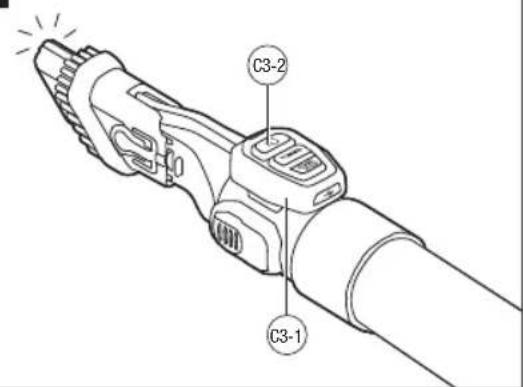
Connect the crevice nozzle to the vacuum hose following the same process of connecting the utility nozzle. Snap the remote control onto the remote-control mount on the vacuum hose. Press the light button on the remote control and the transparent crevice nozzle will light up (Fig. C3).
| C2-1 | Brush-Release Button C2 | -2 Crevice Nozzle |
| C3-1 | Remote Control C3-2 Light Button | |
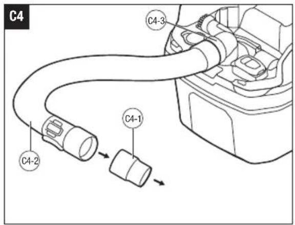
Power-Tool Adapter (Fig. C4)
The power-tool adapter allows the vacuum to connect to a power tool with a 32 mm diameter dust outlet.
With the screw end of the vacuum hose connected to the suction inlet port of the vacuum, insert the power-tool adapter into the other end of the vacuum hose as far as you can until the power-tool adapter is secured in place. Then connect the power-tool adapter to the dust outlet of the power tool.
| C4-1 | Power-Tool Adapter C4-2 | Vacuum Hose | |
| C4-3 | Suction Inlet Port | ||
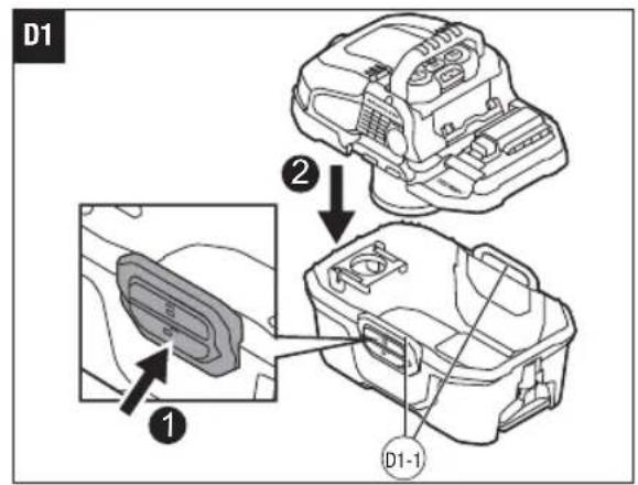
INSTALLING/REMOVING THE POWER HEAD ASSEMBLY
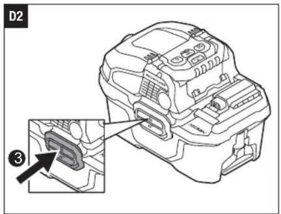
To install, push the lower parts of the collection tank latches, lower the power head assembly onto the collection tank, and then push the upper parts of the collection tank latches (Fig. D1 & D2).
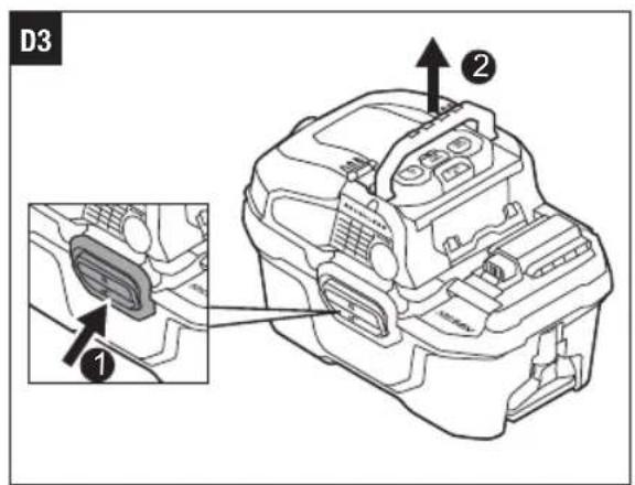
To remove, push the lower parts of the collection tank, and then lift the power head assembly (Fig. D3).
D1-1 Collection Tank Latches
INSTALLING/REMOVING THE DUST BAG
- Unlock the collection tank and remove the power head assembly.
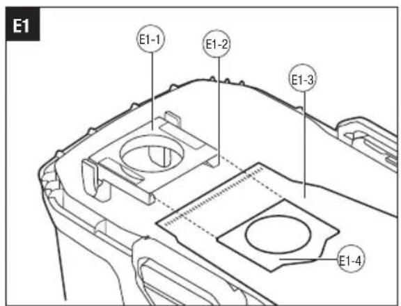
- To install, insert only the plate of the dust bag into the slot of the dust bag bracket until the plate falls down the ribs. Unfold the dust bag manually before collecting dust or debris (Fig. E1).
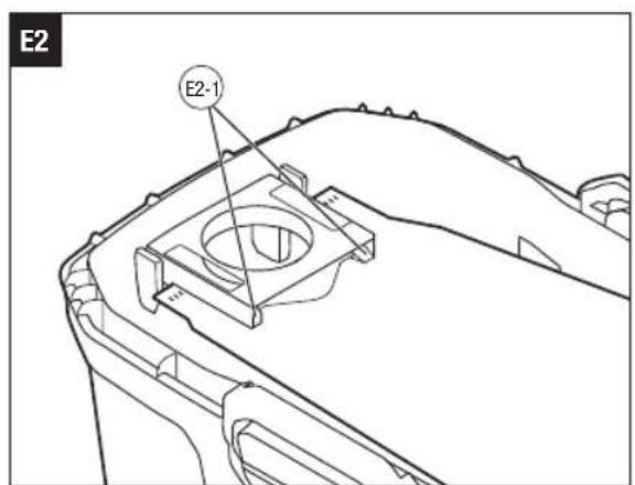
- To remove, slightly lift the plate over the ribs and then pull the plate from the slot to remove the dust bag (Fig. E2).
| E1-1 Dust Bag Bracket E1-2 Slpt | ||
| E1-3 Dust Bag E1-4 Plate | ||
| E2-1 Ribs |
OPERATION
APPLICATION
You may use this product for the purposes listed below:
■ Sucking in liquid waste or dry dust when the suction inlet port is used.
■ Functioning as a blower when the blowing outlet port is used.
ATTACHING/DETACHING THE BATTERY PACK
Use only with EGO's battery packs and chargers listed in Fig. A2.
Refer to corresponding battery packs and chargers manuals for more details.
Fully charge before first use.
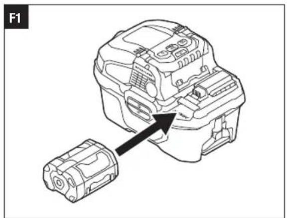
To attach (Fig. F1)
Align the battery ribs with the mounting slots in one and slide the battery pack onto the vacuum until you hear a "click".
To Detach (Fig. F2)
Depress the battery-release button and pull the battery pack out.
F2-1 Battery-Release Button
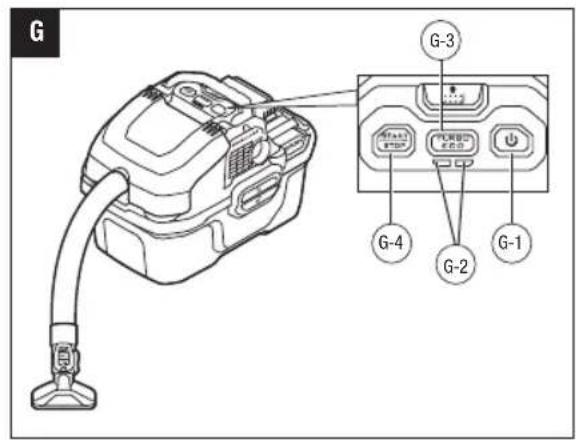
STARTING/STOPPING THE WET/DRY VACUUM (Fig. G)
To Start the Vacuum
- Verify that the power head assembly is installed onto the collection tank and the collection tank is securely locked. Ensure that the vacuum hose and nozzle are connected properly.
NOTE: The vacuum runs only when the power head assembly is securely attached to the collection tank.
- Install the battery pack.
- Press the power button to power up the vacuum.
- Press the speed adjustment button to select ECO speed or TURBO speed. The speed indicators display one or two green lights when the vacuum is in ECO speed or in TURBO speed, respectively.
- Press the start/stop button to start the vacuum.
To Stop the Vacuum
- Once the vacuuming is completed or when the collection tank is full, press the start/stop button to stop the vacuum temporarily.
- Or press the power button to power down the vacuum completely.
- Remove the battery pack.
- Empty the collection tank into a suitable receptacle or drain.
| G-1 Power Button G-2 Speed Indicators | |||
| G-3 | Speed Adjustment Button | G-4 Start/Stop Button | |
POWER BUTTON INDICATOR
| Power Button Indicator | Meaning | Action |
| Solid green | Standby | No actions required. The vacuum will turn off automatically after 1 hour of inactivity. |
| The machine runs properly | Normal operation. | |
| Flashing green continuously | Electronics error | Contact EGO customer service for help. |
EN
REMOTE CONTROL
■ The remote control can be positioned on the vacuum hose during vacuuming (Fig. H1).
- When the vacuum is powered on, you can use the start/stop button on the remote control to start or stop the vacuum. You can also switch the machine between ECO speed and TURBO speed by pressing the TURBO button on the remote control.
■ The remote control can be used as a flashlight by pressing the light button. This can be helpful for cleaning in dark areas, especially when using the crevice nozzle.
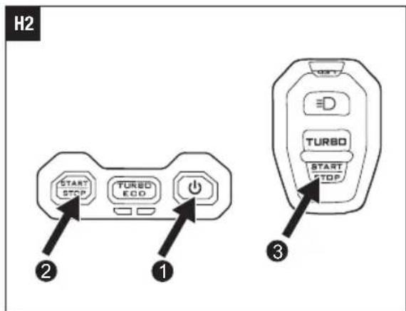
Remote Control Pairing (Fig. H2)
The remote control was paired with the vacuum at the factory. However, if the remote control is damaged or lost, follow the steps below to pair your new remote control with the vacuum.
- Install the battery pack.
- Press the power button to power up the vacuum.
- Press and hold the start/stop button on the vacuum until the power button indicator starts flashing green slowly.
-
Press the TURBO button or the start/stop button on the remote control as soon as the power button indicator starts flashing green slowly.
-
The power button indicator will flash green fast and then shine solid green to indicate the pairing was successful.
| Remote Control Indicator | Meaning Action | |
| Rapidly flashing green | The remote control battery charge is nearly depleted. | Charge the remote control. |
| Slowly flashing green | The remote control is charging. | No action needed. |
| Solid green | The charging of the remote control is complete. | Disconnect the remote control and charging cable from power supply. |
NOTE: During normal operation, the remote control indicator will light one time when the TURBO button or the start/stop button is pressed once.
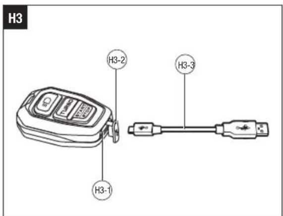
Recharging the Remote Control (Fig. H3)
Periodically the battery inside the remote control will need to be recharged.
WARNING: For this rechargeable Li-ion battery inside the remote control, please be aware of below:
■ Risk of fire and burns.
■ Do not open, crush, heat above 60^ C or incinerate.
■ Do not short circuit.
■ If bulges severely, discontinue use.
- Open the USB-C port cover.
- Connect the USB-C end of the included charging cable to the USB-C port in the remote control.
- Connect the other end of the charging cable to a compatible USB power adapter/charger (not included). It may take up to 2 hours to charge a fully discharged battery.
- When finished charging, disconnect the charging cable and close the USB-C port cover to protect the USB-C port from contamination.
| H1-1 | Light Button H1-2 TURBO | Button | |
| H1-3 | Remote Control Indicator | H1-4 | Start/Stop Button |
| H3-1 | USB-C Port H3-2 USB-C | Port Cover | |
| H3-3 | Charging Cable | ||
WORKING WITH THE VACUUM
Wet Vacuuming Operation
■ Do not use the dust bag during wet vacuuming operation.
■ Turn off the vacuum immediately when the collection tank is full. Empty the collection tank into a suitable receptacle or drain. Ensure that the filter is completely dry before the next wet vacuuming operation or use a dry replacement filter.
■ Clean the interior of the collection tank, the filter, and accessories periodically, more often when used to pick up wet, sticky materials.
■ Use a dry filter for subsequent dry vacuuming. We recommend purchasing an extra filter when frequently alternating between wet and dry vacuuming and swapping them out as needed.
■ To prevent mold formation, completely dry the filter and the collection tank.
Dry Vacuuming Operation
■ Make sure the filter is completely dry after wet vacuuming or use a second dry filter for dry vacuuming. Damp or wet filters will get clogged with dust or get moldy.
■ To reduce exposure to silica dust, use the dust bag.
■ When vacuum power is weak or there is no vacuum power, the dust bag or collection tank is full. Turn off the vacuum immediately.
■ Empty the collection tank into a suitable refuse container.
Blower Operation
WARNING: Always wear eye protection when using this machine as a blower.
WARNING: Do not blow flammable or combustible materials, such as gasoline, or use in areas where such materials may be present. Fire could result.
WARNING: Do not direct the airflow in the direction of people or pets.
MAINTENANCE
WARNING: To prevent serious personal injury, remove the battery pack from the product before servicing, cleaning, changing attachments, or removing material from the unit.
GENERAL MAINTENANCE
Avoid using solvents when cleaning plastic parts. Most plastics are susceptible to damage from various types of commercial solvents and may be damaged by their use. Use a clean cloth to remove dirt, dust, oil, grease, etc.
WARNING: Do not at any time allow brake fluids, gasoline, petroleum-based products, penetrating oils, etc. to come in contact with plastic parts. Chemicals can damage, weaken or destroy plastic which may result in serious personal injury.
WARNING: To reduce the risk of fire, personal injury, and product damage due to a short circuit, never immerse your machine, battery pack or charger in fluid or allow a fluid to flow inside them. Corrosive or conductive fluids, such as seawater, certain industrial chemicals, and bleach or bleach containing products, etc., can cause a short circuit.
EMPTYING THE COLLECTION TANK
- Remove the power head assembly from the collection tank.
- Remove the dust bag if the dust bag is installed.
- Empty liquid in the collection tank into a suitable receptacle or drain.
-
Clear all dirt and debris from the collection tank and clean with mild soap and water.
-
Allow the collection tank to dry before reassembling the power head assembly.
FILTER MAINTENANCE
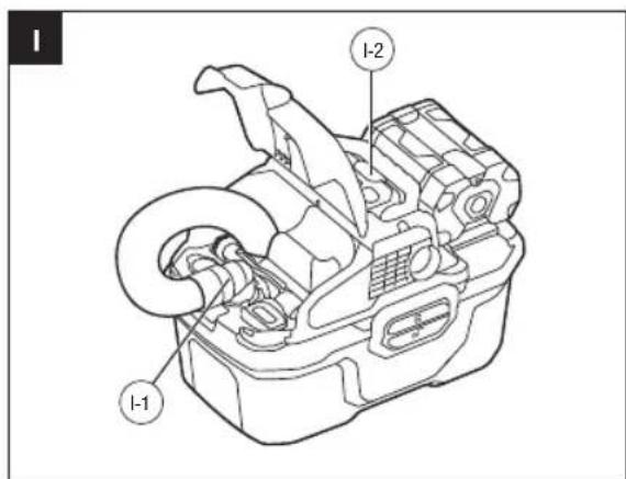
Filter Self-Cleaning System (Fig. I)
- Connect the vacuum hose to the suction inlet port of the vacuum and fully insert the nozzle end of the hose into the filter self-cleaning plug.
- Install the battery pack and press the power button to power on the machine.
-
Select the desired speed and press the start/stop button to turn on the machine.
-
Press the filter self-cleaning button to clean the filter.
TIP: To achieve the best cleaning effect, it is recommended to select TURBO speed and press and hold the filter self-cleaning button for 3 seconds. Do this a total of five times to thoroughly clean the filter.
| I-1 Suction Inlet Port I-2 | Filter Self-cleaning Button |
Washing the Filter
Remove the battery pack and examine the filter by removing the power head assembly. If the filter is still dirty after following the steps in the section “Filter Self-cleaning System”, remove the filter and rinse it gently in cold water. Allow the filter to dry completely and reinstall it.
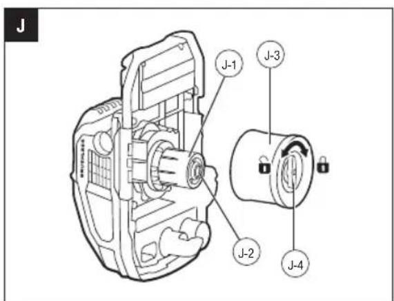
Replacing the Filter (Fig. J)
WARNING: Check the filter periodically and replace if worn out or damaged. Using damaged filter can lead to release of unwanted airborne contaminants from the tank.
- Lift the power head assembly and put it on its side.
- Rotate the filter-release knob counterclockwise and then pull the filter away from the power head assembly.
- Use a moist piece of cloth to remove any dust and debris from the filter area.
- To install a new or cleaned filter, align the position of the filter-release knob with the slot in the center of the mounting bracket and slowly push the filter in place. Adjust the position of the filter-release knob to align with the slot position if you are unable to push the filter fully onto the mounting bracket. Rotate the filter-release knob clockwise to lock the filter in place.
EN
| J-1 Mounting Bracket J-2 Slot | |
| J-3 Filter J-4 Filter-release Knob |
STORING THE VACUUM
- Remove the battery pack from the vacuum.
- Clean the vacuum thoroughly and allow the vacuum to dry fully before storing it.
- Store the vacuum in a dry, well-ventilated area, locked-up or up high, out of the reach of children. Do not store the vacuum on or adjacent to fertilizers, gasoline, or other chemicals.
PROTECTING THE ENVIRONMENT

Do not dispose of electrical equipment, used battery and charger into household waste! Take this product to an authorized recycler and make it available for separate collection. Electric tools must be returned to an environmentally compatible recycling facility.
TROUBLESHOOTING
EN
| PROBLEM CAUSE SOLUTION | ||
| The vacuum fails to start. | ■ Battery pack charge is low.■ Battery pack is not installed properly. | ■ Charge the battery pack.■ Slide the battery pack onto the vacuum until it snaps into position. |
| The vacuum power becomes weak and then the vacuum cleaner stops working. | ■ There is a blockage in the vacuum hose or the suction inlet. | ■ Check and clear the blockage in the vacuum hose or the suction inlet. |
| ■ The filter is clogged by fine dust. | ■ Clean the filter following the section“FILTER MAINTENANCE” in this manual. | |
| ■ The collection tank is full. | ■ Empty the collection tank. | |
| ■ Battery pack charge is low. | ■ Charge the battery pack. | |
| The machine is running but there is no suction. | ■ The power head assembly is not installed onto the collection tank correctly. | ■ Ensure the power head assembly is installed onto the collection tank correctly. |
| Dust escapes from the blowing outlet port. | ■ Filter is missing or installed incorrectly. | ■ Check the filter for correct installation. |
| ■ Filter is damaged. | ■ Replace with a new filter. | |
| The vacuum cannot be controlled through the remote control. | ■ The remote control is not paired with the vacuum. | ■ Pair the remote control with the vacuum following the chapter “Remote Control Pairing” in this manual. |
| ■ The remote control charge is low. | ■ Charge the remote control. | |
| ■ The remote control is damaged. | ■ Use a new remote control and perform the remote control pairing. | |
WARRANTY
EGO WARRANTY POLICY
Please visit the website egopowerplus.eu for full terms and conditions of the EGO Warranty policy.
AUFBAU DES NASS/TROCKEN-SAUGERS (ABB. A1)
LISTA DE PEÇAS (IMAGEM A1)
ACESSÓRIOS RECOMENDADOS
SÅDAN MONTERES/AFMONTERES ST∅VSUGERPOSEN
T∅MNING AF OPSAMLINGSBEHOLDEREN
GENERELT VEDLIKEHOLD
POLITYKA GWARANCYJNA EGO
CITIȚI MANUALUL DE INSTRUCTIUNI
INSTALAREA/SCOATEREA SACULUI DE PRAF
The Ground Truth image displays a single, solid horizontal line. According to Rule 2 (UNDERSCORE & LINE RULES), this is a stylistic or background line, not a placeholder underscore. Therefore, the OCR result must ignore it and output nothing or only meaningful text. The provided OCR content is "____", which consists of four underscores. This is an incorrect interpretation of the line as a placeholder, violating the rule that stylistic lines must be ignored. The OCR has hallucinated underscores where none should exist based on the GT's visual context. Hence, the OCR result is inconsistent with the Ground Truth.
LUGEGE KASUTUSJUHENDIT
g y z u y y z u (656. A1)
modification of the following text:
g_mg_dg_m^6m b_gm^1s_hg_m^2s_ps_3g_m^6n (65b. C4)
g\& g\& g\& g\& g\& g\& g\& g\& g\& g\& g 32 \& \& \& \& \& \& \& \& \& \& \& \& \& \& \& \& _1^*g^^^^^^^^^^^^^^^^^^^^^\&
هذه presentsese Household's profile to discuss the relationship between the household's personal and social relationships. The household's relationship is a strong relationship with the household's personal relationship.
.הכלההוּרָהוּרָהוּרָהוּרָהוּרָהוּרָהוּרָהוּרָהוּרָהוּרָהוּרָהוּרָהוּרָהוּרָהוּרָה
natural_image
Line drawing of a mechanical device casing with labeled buttons and ports (no readable text or symbols)WDV0300E
56 1-הכלהה/הכלהה HE
- EN READ ALL INSTRUCTIONS!
- READ OPERATOR'S MANUAL
- SAFETY SYMBOLS
- SYMBOL MEANING
- SAFETY INSTRUCTIONS
- PACKING LIST (FIG. A1)
- RECOMMENDED ACCESSORIES
- DESCRIPTION
- KNOW YOUR WET/DRY VACUUM (Fig. A1)
- EN
- ASSEMBLY
- CONNECTING/DISCONNECTING THE VACUUM HOSE
- To Connect/Disconnect with Suction Inlet Port
- INSTALLING/REMOVING THE NOZZLES
- Utility Nozzle (Fig. C1)
- Crevice Nozzle
- Power-Tool Adapter (Fig. C4)
- INSTALLING/REMOVING THE POWER HEAD ASSEMBLY
- INSTALLING/REMOVING THE DUST BAG
- OPERATION
- APPLICATION
- ATTACHING/DETACHING THE BATTERY PACK
- Fully charge before first use.
- To attach (Fig. F1)
- To Detach (Fig. F2)
- STARTING/STOPPING THE WET/DRY VACUUM (Fig. G)
- To Start the Vacuum
- To Stop the Vacuum
- REMOTE CONTROL
- Remote Control Pairing (Fig. H2)
- Recharging the Remote Control (Fig. H3)
- WORKING WITH THE VACUUM
- Wet Vacuuming Operation
- Dry Vacuuming Operation
- Blower Operation
- MAINTENANCE
- GENERAL MAINTENANCE
- EMPTYING THE COLLECTION TANK
- FILTER MAINTENANCE
- Filter Self-Cleaning System (Fig. I)
- Washing the Filter
- Replacing the Filter (Fig. J)
- STORING THE VACUUM
- PROTECTING THE ENVIRONMENT
- TROUBLESHOOTING
- WARRANTY
- EGO WARRANTY POLICY
- AUFBAU DES NASS/TROCKEN-SAUGERS (ABB. A1)
- LISTA DE PEÇAS (IMAGEM A1)
- ACESSÓRIOS RECOMENDADOS
- SÅDAN MONTERES/AFMONTERES ST∅VSUGERPOSEN
- T∅MNING AF OPSAMLINGSBEHOLDEREN
- GENERELT VEDLIKEHOLD
- POLITYKA GWARANCYJNA EGO
- CITIȚI MANUALUL DE INSTRUCTIUNI
- INSTALAREA/SCOATEREA SACULUI DE PRAF
- LUGEGE KASUTUSJUHENDIT
Brand : EGO
Model : Power+ WDV0300E
Category : Vacuum Cleaner