
YT-07190 - Industrial vacuum cleaner Yato - Free user manual and instructions
Find the device manual for free YT-07190 Yato in PDF.

| Product type | Industrial vacuum for oil drainage |
| Brand | Yato |
| Model | YT-07190 |
| Power supply | Pneumatic (compressed air) |
| Maximum extraction pressure | 0.8 MPa |
| Recommended extraction pressure | 0.7 MPa |
| Maximum reservoir drain pressure | 0.18 MPa |
| Required air flow | 150 l/min |
| Main reservoir capacity | 70 L |
| Test reservoir capacity | 10 L |
| Bowl capacity | 10 L |
| Vacuum generated | 0 ~ -1 MPa |
| Recommended liquid temperature | 40-60 °C |
| Sound level (acoustic pressure) | 101.2 ± 3 dB(A) |
| Sound level (acoustic power) | 119.8 ± 3 dB(A) |
| Weight | 20 kg |
| Extraction methods | By vacuum or by gravity |
| Safety valve | Yes |
| Pressure gauge | Yes |
| Probes included | Plastic and metal |
| Wheels for transport | Yes |
| Recommended use | Extraction of engine oil, transmission oil, etc. |
| Prohibited liquids | Gasoline, solvents, diesel, alcohol, brake fluid |
| Recommended maintenance | External cleaning with aqueous cleaner; internal rinsing every 6 months |
Frequently Asked Questions - YT-07190 Yato
User questions about YT-07190 Yato
0 question about this device. Answer the ones you know or ask your own.
Ask a new question about this device
Download the instructions for your Industrial vacuum cleaner in PDF format for free! Find your manual YT-07190 - Yato and take your electronic device back in hand. On this page are published all the documents necessary for the use of your device. YT-07190 by Yato.
USER MANUAL YT-07190 Yato
natural_image
Industrial machine with control panel and wheels, no visible text or symbols on the device itselfCE
PL EN DE RU UA LT LV CZ SK HU RO ES FR IT NL GR
natural_image
Two-panel black-and-white photo showing a mechanical assembly with a tool inserted, no visible text or symbols.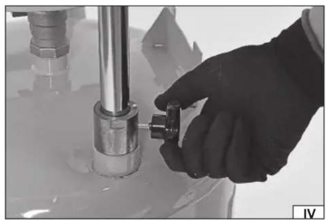
natural_image
Close-up of a gloved hand adjusting a mechanical component with a metallic shaft and pipe fitting (no visible text or symbols)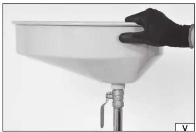
natural_image
Hand holding a white funnel-shaped container with a metal valve, mounted on a stand (no text or symbols visible)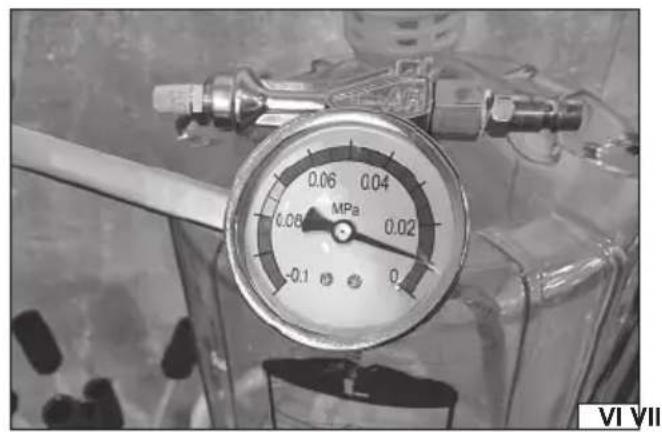
natural_image
Close-up of a pressure gauge (MPa) with no visible text or symbols on the dial, set against a transparent background (no readable labels or symbols)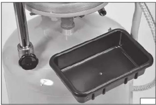
natural_image
Close-up of a mechanical device with a rectangular tray and pipe fittings (no visible text or symbols)natural_image
Four-panel black-and-white photo showing a mechanical assembly with labeled components, no visible text or symbols.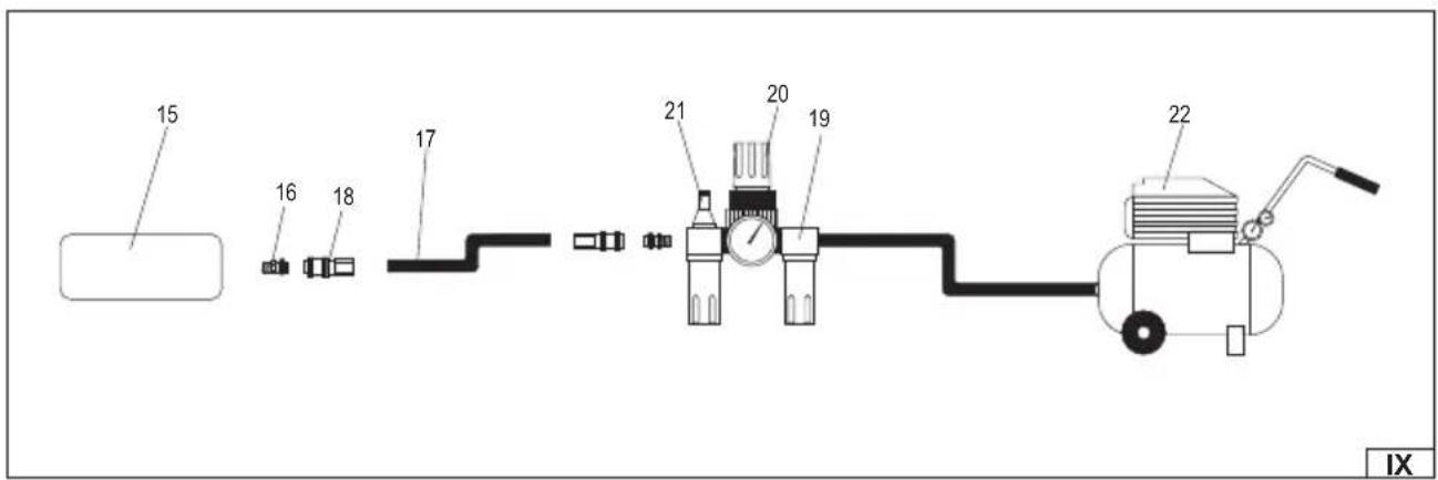
natural_image
Two mechanical components: one with coiled tubing and connectors, the other with a threaded connector labeled '12' (no text or symbols beyond labels)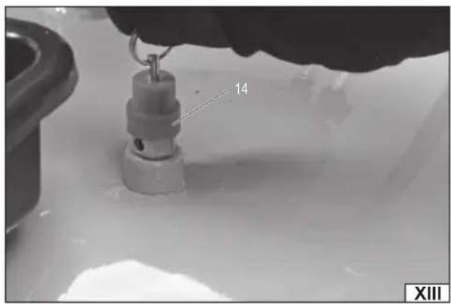
natural_image
Close-up of a hand holding a small mechanical component with a label '14' (no readable text or symbols beyond the number)PL
-
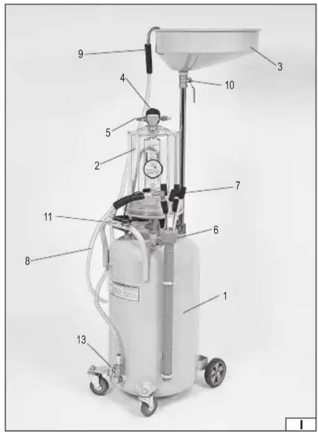
main tank
-
test tank
-
bowl
-
pressure gauge
-
test tank air intake
-
main tank air intake
-
extraction probe
-
fl exible probe hose
-
main tank emptying hose
-
pan valve
-
valve under the test tank
-
main tank air intake valve
-
main tank valve
-
safety valve
-
tool
-
hose socket
-
hose
-
hose connector
-
grease gun
-
reducer
-
fi lter
-
compressor
DE
Read the operating instruction
Wear protective goggles
Schutzbrille tragen
Wear hearing protectors
Gehörschutz tragen
Air connection diameter
The oil drain and evacuator allows for quick, efficient and safe removal and collection of consumable fluids in the form of engine oil, transmission oil, etc. from vehicles and other machines equipped with a combustion engine. The product is not used to collect flammable liquids, e.g. petrol, solvents, diesel, alcohol, etc. and corrosive liquids, e.g. brake fluid. The correct, reliable and safe operation of the product depends on its proper use, therefore:
Read and keep the entire Manual before the first use of the tool.
The supplier shall not be liable for any damage resulting from failure to comply the safety instructions and recommendations specified in this manual.
ACCESSORIES
The product is delivered complete but requires assembly before operation. The product is delivered with probes which allow access to consumable fluid tanks in combustion engines.
SPECIFICATION
| Parameter Units Value | ||
| Catalogue No. YT-07190 | ||
| Maximum extraction pressure [MPa] 0.8 | ||
| Recommended extraction pressure [MPa] 0.7 | ||
| Maximum tank-emptying pressure [MPa] 0.18 | ||
| Required air flow [l/min.] 150 | ||
| Main tank capacity [l] 70 | ||
| Inspection tank capacity | [l] 10 | |
| Bowl capacity | [l] 10 | |
| Liquid temperature (°C) | [°C] | 40-60 |
| Generated vacuum | [MPa] | 0 ~ -1 |
| Noise | ||
| - sound pressure | [dB(A)] | 101,2±3 |
| - acoustic power | [dB(A)] | 119,8±3 |
| Weight | [kg] | 20 |
GENERAL SAFETY CONDITIONS
WARNING! When operating a pneumatic tool, it is recommended that you always observe basic safety principles, including those listed below, in order to reduce the risk of fire, electric shock and injury.
Please read and keep the entirety of this instruction manual before using the tool.
CAUTION! Read all of the following instructions. Failure to do so may result in electric shock, fire, or personal injury. The term "pneumatic tool" used in these instructions refers to all tools operating by means of a compressed air stream at the correct pressure.
PLEASE OBSERVE THE FOLLOWING INSTRUCTIONS
General safety conditions
Due to multiple hazards, read and understand the safety instructions before starting installation, operation, repair, maintenance and alteration of accessories or when working in the vicinity of a pneumatic tool. Failure to do so may result in serious injury. Pneumatic tools may only be installed, adjusted and assembled by qualified and trained personnel. Do not modify the pneumatic tool. Modifications can reduce efficiency and safety and increase the risk for the tool operator. Do not throw away the safety instructions, they should be handed over to the tool operator. Do not use the pneumatic tool if it is damaged. The employer/user should contact the manufacturer to replace the rating plate whenever necessary.
Hazards connected with work
Use of the tool may expose the operator's body to the risk of high-pressure injections or contact with vacuum. Do not point the tank oil outlet and the probe inlet in your direction or towards other people and animals. Do not apply the outlet or inlet to the skin. Wear suitable gloves to protect your hands. The operator and the maintenance personnel should be physically able to cope with
EN
the quantity, weight and power of the tool. Hold the tool correctly. Be prepared to counter normal or sudden movements and have both hands free. Keep your feet in balance and in a safe position. The pressure on the start and stop device should be released in the event of a power failure. Use only the lubricants recommended by the manufacturer. Avoid uncomfortable postures as well as positions which prevent countering normal or sudden movement of the tool.
Hazards connected with repetitive movements
When using a pneumatic tool for work entailing repetitive movements, the operator is exposed to the discomfort of hands, arms, shoulders, neck or other parts of the body. When using a pneumatic tool, the operator should take a comfortable posture to ensure the feet are correctly positioned, and avoid strange or unbalanced postures. The operator should change the posture over a long period of time to avoid discomfort and fatigue. If the operator experiences symptoms such as persistent or repeated discomfort, pain, pulsating pain, tingling, numbness, burning or stiffness, they should not ignore them, inform the employer and consult a physician.
Hazards connected with accessories
Disconnect the tool from the power source before changing the inserted tool or accessory. Use accessories and consumables only in the sizes and types recommended by the manufacturer. Do not use cracked or deformed accessories. Check the condition of the accessories prior to each use.
Hazards connected with the workplace
Slips, stumbles and falls are the main causes of injury. Beware of slippery surfaces caused by using the tool, as well as tripping hazards caused by the air system. Proceed with caution in an unfamiliar environment. There may be hidden hazards, such as electricity or other utility lines. The pneumatic tool is not intended for use in potentially explosive zones and is not insulated from contact with electricity. Make sure that there are no electric cables, gas pipes, etc. which could pose a risk in the case of damage with the tool.
Noise hazard
Exposure to high levels of noise can cause permanent and irreversible hearing loss and other problems such as tinnitus (ringing, buzzing, whistling or buzzing in ears). A risk assessment and the implementation of appropriate control measures for these hazards are necessary. Use hearing protection in accordance with the employer's instructions and in accordance with hygiene and safety requirements. The operation and maintenance of the pneumatic tool must be carried out in accordance with the instructions in the manual in order to avoid an unnecessary increase in noise levels. Selection, maintenance and replacement of wear parts/inserted tools must be carried out in accordance with the instructions in the manual in order to prevent unnecessary noise build-up. If the pneumatic tool has a silencer, always make sure that it is installed correctly when using the tool.
Additional safety instructions for pneumatic tools
Pressurised air can cause serious injury:
- always disconnect the air supply, release the air pressure from the hose and disconnect the tool from the air supply when not in use, before changing accessories or carrying out repairs;
- never point the air stream at yourself or anyone else.
Hitting with the hose can cause serious injury. Always check for damaged or loose hoses and connectors. Direct cold air away from hands. Whenever universal screwed connections (dog connections) are used, safety pins and safety connectors must be used to prevent damage to the connections between the hoses and between the hose and the tool. Do not exceed the maximum air pressure specified for the tool. Never carry the tool holding it by the hose.
OPERATING CONDITIONS
The oil drain and evacuator may only be used for the extraction and temporary storage of engine oil, transmission oil, etc. from vehicles and other machines equipped with a combustion engine. The product is not used for extraction and temporary storage of flammable liquids, e.g. petrol, solvents, diesel, alcohol, etc. and corrosive liquids, e.g. brake fluid.
Make sure that the compressed air source generates the correct working pressure and provides the required airflow. If the supply air pressure is too high, a pressure reducer with a safety valve must be used. Applying too high a pressure can lead to rupture of the product components, which can cause serious injury.
The pneumatic tool must be fed through the filter and lubricator system. This will ensure that the air is both clean and moistened with oil. Check the condition of the filter and lubricator before each use and clean the filter if necessary or make up for oil shortage in the lubricator. This will ensure the correct operation of the tool and extend its service life.
In the case of heavy loads, a recoil force may be generated towards the tool operator. It is necessary to adopt such a posture during work to be able to counteract these forces effectively.
Always make sure that all wrenches and tools used for adjusting are removed before starting work.
Always use protective goggles when adjusting and using the product.
Check the cables and adapters for leaks before each use.
Before connecting to the compressed air source, make sure that all valves and switches are in the "OFF" position. Do not exceed the maximum air pressure of 0.8 MPa / 0.18 MPa for extracting / emptying the contents of the tank
EN
Never exceed the temperature range of the oil to be extracted. The engine oil temperature should be between 40^ C and 60^ C before extraction. If the oil temperature is too low, the oil will be too dense for effective extraction. Excessive heat can damage the plastic parts of the product and cause serious burns.
Do not use this machine for applications not listed in the manual. Extraction of fluids other than those specified in the manual may cause injuries and fi re, as well as damage to the product.
When extracting oil from a combustion engine, the engine must not be in motion.
Observe local waste oil disposal regulations. Oil is not an environmentally inert substance. Used motor oil should be properly disposed of or recycled. Contact your local waste authority for information on recycling. Never reuse the used motor oil.
During oil extraction do not approach the machine with fire, also avoid strong sources of heat such as radiators or heaters. Do not smoke while operating the machine.
PRODUCT OPERATION
Caution! Make sure that the product has been disconnected from the compressed air supply before starting any assembly or disassembly operations. Also make sure that the pressure accumulated in the product tanks has been released. To do so, open all valves. The valve is open if its lever is parallel to the valve line. Moving the lever to the position perpendicular to the valve line closes the valve.
Threaded connections must be tightened with a force not greater than is required to achieve tightness. Tightening the threaded connections with too great a force can damage the seals. PTFE tape can be used to improve the tightness of threaded connections.
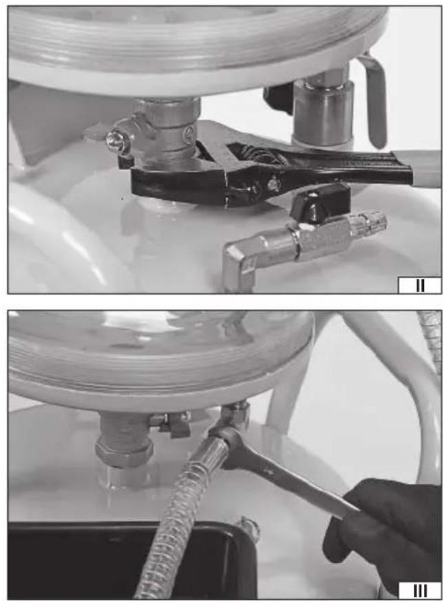
Product assembly
First, fix the test tank to the main tank. Screw the ball valve coupling on the underside of the tank to the main tank inlet (II). Screw the flexible hose with the probe tip attachment to the test tank inlet (III).
Loosen the fixing screw of the pipe connecting the main tank to the pan and pull out the pipe so that the inlet is above the test tank, then tighten the fixing screw to lock the extended pipe (IV). Screw the pan to the pipe inlet (V).
Screw the pressure gauge to the test tank air inlet (VI).
Place the tray on the main tank hooks (VII). The tray allows for temporary storage of oil pan plugs during oil extraction.
Insert the extraction probe handle into the bracket on the side wall of the main tank and place the probes in it (VIII).
Connecting the tool to the pneumatic system
Regardless of whether the compressed air source is connected for oil extraction or main tank emptying, the tool should be connected as shown in the figure (IX). The figure shows the recommended manner of connecting the tool to the pneumatic system.
This will ensure the most efficient use of the tool and also prolong the tool's service life.
Apply a few drops of SAE 10 viscous oil used for pneumatic tools into the air inlet.
The output of the tool can be adjusted by changing the air pressure supplied to the tool.
It is forbidden to exceed the maximum pressure specified in the technical data table.
Connect the tool to the pneumatic system using a hose with an internal diameter of 10 mm / 3/8". Make sure the hose has a durability of at least 1.38 MPa.
Extraction of oil by vacuum method
Make sure the probe valve at the end of the hose is closed and then connect the selected extraction probe to it. Remove the protective cover, then slide the connection of the extraction probe (X).
Plastic probes can be shaped to some extent, which can be useful if you need to access the difficult-to-reach parts of the oil tank.
However, excessive bending of the probe should be avoided, as it may lead to clogging of the probe and its permanent damage. Metal probes cannot be shaped.
Make sure that the valve under the test tank is closed.
Make sure that the main tank valve is closed.
Adjust the pressure in the compressed air source so that it does not exceed the maximum extraction pressure given in the technical data table.
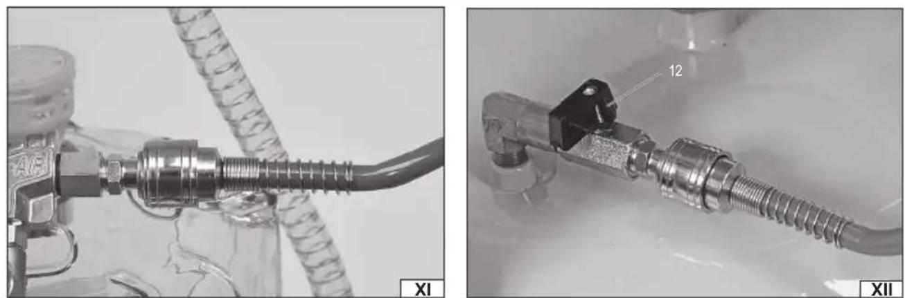
Connect the compressed air source to the test tank (XI), then start supplying air to the test tank, which will create a vacuum in the test tank. Observe the pressure gauge. If the pointer is in the yellow area of the pressure gauge scale, stop the supply of air to the test tank.
Insert the probe into the tank from which the oil is to be extracted and then open the probe valve. Vacuum in the test tank will result in oil extraction.
Observe the scale on the tank, the oil level must not exceed the line marked "STOP". If the oil level in the test tank comes close to this line, remove the probe from the oil tank and allow the pressure inside the oil tank to equalise. Then close the probe valve and open the valve under the test tank to transfer the contents of the test tank to the main tank. After emptying the test tank, close the valve under the test tank.
If the vacuum generated does not permit extraction of all the oil from the tank, close the probe valve, repeat the vacuum generation
EN
procedure in the test tank, and then resume oil extraction.
There is no need to empty the test tank during vacuum generation, but this is recommended because of the higher oil extraction efficiency of an empty test tank.
Extraction of oil by gravity method
This method does not use the test tank or the compressed air source.
Make sure that the pan underneath it is closed. Make sure that the main tank valve is closed.
Then place the tool so that the pan is under the tank oil outlet. Open the tank oil outlet and allow the oil to drain into the pan. After emptying the tank, close the oil outlet, open the pan valve and allow the oil to flow from the pan into the main tank. After emptying the pan, close the pan valve.
Emptying the main tank
Caution! Before emptying the main tank, make sure that the valve under the test tank and the pan valve are closed. Otherwise, emptying the main tank may fail and the oil stored in the main tank may escape into the pan and/or control tank.
The main tank has an oil level indicator on the side surface. If the oil reaches the top edge of the indicator, empty the main tank.
Fix the end of the tank emptying hose to the tank into which the oil from the main tank will be transferred.
Adjust the pressure in the compressed air source so that it does not exceed the maximum tank emptying pressure given in the technical data table.
Make sure the air inlet valve on the container is closed and then connect the compressed air source to the inlet (XII).
Open the valve of the main tank, if the tip of the tank emptying hose is below the oil level in the main tank, the oil will automatically drain from the main tank on the principle of connected vessels. Open the air inlet valve to the main tank, the compressed air entering the main tank will displace the oil stored in the main tank. After the oil has ceased to flow out of the main tank, close the air inlet valve, disconnect the compressed air source, and then wait until all pressure of the air injected into the main tank has been discharged, and close the main tank valve.
The main tank shall be equipped with a safety valve which, if the pressure limit for the tank is exceeded, releases excess pressure.
The valve can also be lifted manually (XIII) to equalise the pressure in the main tank.
MAINTENANCE, TRANSPORT AND STORAGE
Clean the external surfaces of the product with a diluted water-based cleaning agent designed to remove engine oil residues. Do not use flammable cleaning agents, solvents, petrol or alcohol. Do not use corrosive or abrasive agents. Clean the pan in the same manner as the external surfaces.
The interior of the product should be rinsed at least once every six months with water-based cleaning agents, using vacuum and gravity methods. This will allow the removal of contaminants which have entered the tanks together with the used oil.
Transport the product over short distances, e.g. within the workshop when using the product wheels. In the case of transport over longer distances, the product should be cleaned, disassembled and transported in the factory packaging. Regardless of the distance, the product should always be transported disconnected from the compressed air source and with equal pressure in both tanks.
The product should be stored disconnected from the compressed air source and with equal pressure in both tanks. The tanks and the pan should be emptied and cleaned for storage. The product can be stored assembled or disassembled. Keep out of reach of unauthorised persons, especially children. The place of storage should protect against high temperatures, direct sunlight, and provide good ventilation so that no condensation of water vapour can form on the product.
DE
GERÄTEBESCHREIBUNG
CARACTÉRISTIQUES DU PRODUIT
CONDITIONS D'EXPLOITATION
DECLARATION OF CONFORMITY
0824/YT-07190/EC/2024
We declare and guarantee with full responsibility that the following products:
Pneumatic oil drain extractor; 0,8/0,18 MPa; 150 l/min; 90 l; item no. YT-07190
meet requirements of the following European Standards / Technical Specifications:
EN ISO 12100:2010
and fulfill requirements of the following European Directives:
2006/42/EC Machinery and safety elements
Serial number: concern all serials numbers of item(s) mentioned in this declaration
The person authorized to compile the technical file:
Tomasz Zych
(Place and date of issue)
(Name and signature of authorized person)
TOYA S.A.