
Sol-R 3 AVA Grip Add-On - Game controller THRUSTMASTER - Free user manual and instructions
Find the device manual for free Sol-R 3 AVA Grip Add-On THRUSTMASTER in PDF.
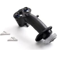


| Product Type | Flight Simulation Add-On Grip |
| Brand | Thrustmaster |
| Model | Sol-R 3 AVA Grip Add-On |
| Base Compatibility | Sol-R 5 Base, AVA, HOTAS Magnetic Base (with Warthog Converter) |
| Number of Buttons | Multiple action buttons, triggers (including a dual-stage trigger), removable buttons |
| Analog Mini-Stick | 1 |
| Hat Switch | 1, 8 directions, can be disabled |
| Scroll Wheel | 1 |
| Rudder | Via grip rotation, lockable with 2 mm Allen key |
| Ambidextrous | Yes, interchangeable right-handed and left-handed thumb rests, ambidextrous wrist rest |
| Height Adapter | Removable, for right-handed and left-handed |
| Cams Included | 2 STAR cams (for AVA base) |
| Programming Software | T.A.R.G.E.T. (advanced programming) |
| Firmware Update | Required depending on base (see support site) |
| Power Supply | Via base connected to PC |
| Maintenance | Clean with a dry cloth |
| Safety | Do not force during assembly; risk of pinching between base and shaft |
| Spare Parts | Contact Thrustmaster support |
| General Information | Requires a compatible base; firmware update mandatory |
Frequently Asked Questions - Sol-R 3 AVA Grip Add-On THRUSTMASTER
User questions about Sol-R 3 AVA Grip Add-On THRUSTMASTER
0 question about this device. Answer the ones you know or ask your own.
Ask a new question about this device
Download the instructions for your Game controller in PDF format for free! Find your manual Sol-R 3 AVA Grip Add-On - THRUSTMASTER and take your electronic device back in hand. On this page are published all the documents necessary for the use of your device. Sol-R 3 AVA Grip Add-On by THRUSTMASTER.
USER MANUAL Sol-R 3 AVA Grip Add-On THRUSTMASTER
PC (Windows® 10/11)
User Manual

Carefully read the instructions provided in this manual before installing the product, before any use of the product and before any maintenance. Be sure to follow the safety instructions. Failure to follow these instructions may result in accidents and/or damage. Keep this manual so that you can refer to the instructions in the future.
TABLE OF CONTENTS
- BOX CONTENTS......6
- TECHNICAL FEATURES......7
- INFORMATION REGARDING USE OF THE FLIGHT STICK GRIP ......9
- ASSEMBLY....11
Mapping 13
Rudder function....19
Multidirectional point of view hat switch.....21
- CONFIGURING THE FLIGHT STICK GRIP...24
Right-handed or Left-handed mode.....24
Example of configuration with a Sol-R* base 25
Example of configuration with an AVA* base or a HOTAS Magnetic Base* base....28
Changing from Right-handed mode to Left-handed mode 29
Changing from Left-handed mode to Right-
handed mode 33
Height adapter....37
- COMPATIBILITY......38
Bases....39
Cams....40
- T.A.R.G.E.T ADVANCED PROGRAMMING
SOFTWARE 41
Installation 41
Main features....42
- FAQ AND TECHNICAL SUPPORT......43
SOL-R3
A V A
ADD-ON GRIP
Enjoy a stellar experience with the Sol-R 3 AVA Add-On Grip flight stick grip: it will accompany you right to the heart of your space battles and explorations.
This manual will help you install and use your Sol-R 3 AVA Add-On Grip in the best possible conditions. Before taking off, be sure to read the instructions and warnings carefully: they will help you get the maximum amount of enjoyment out of your product.

Updating the firmware
In order for the Sol-R 3 AVA Add-On Grip flight stick grip to work properly with video games, you need to update the base's firmware.
- If you are using a Sol-R 5 Base base, please visit https://support.thrustmaster.com/product/sol-r-5-base
- If you are using an AVA base, please visit https://support.thrustmaster.com/product/ava
- If you are using a HOTAS Magnetic Base base, please visit https://support.thrustmaster.com/product/hotas-magnetic-base
Select Drivers and follow the instructions, including the downloading and installation procedure.
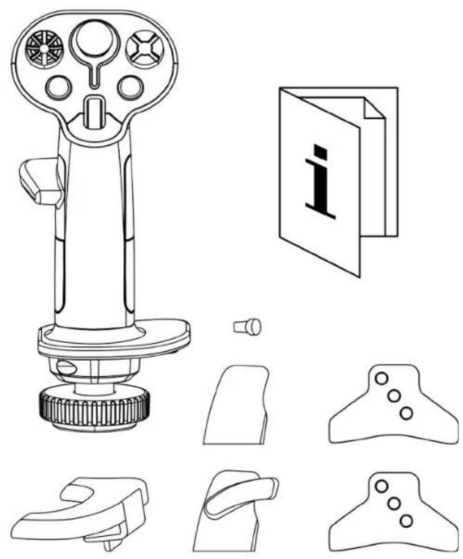
1. Box contents
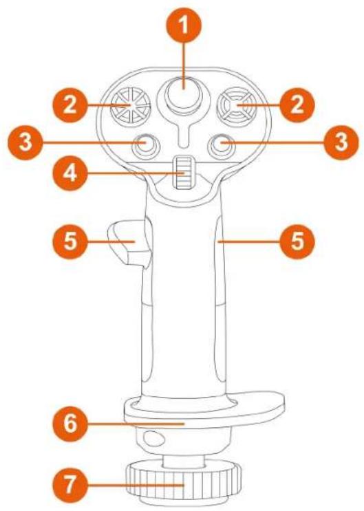
2. Technical features
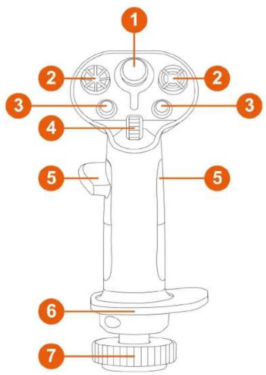
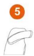
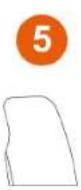
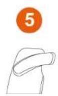
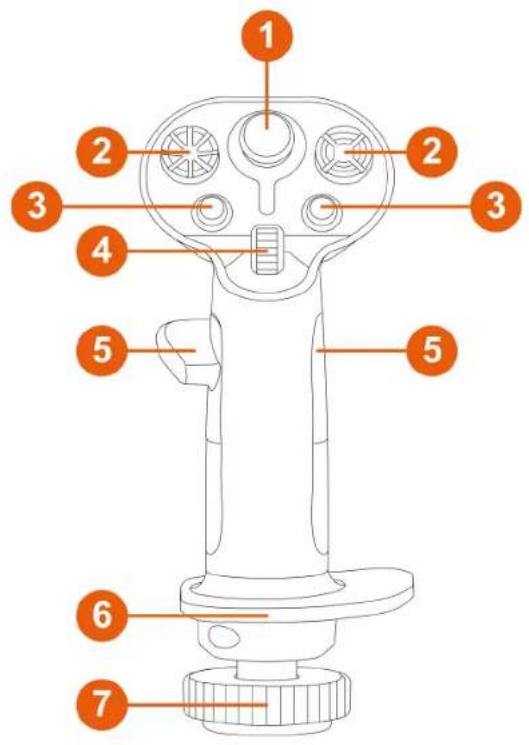
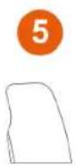
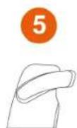
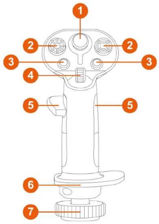
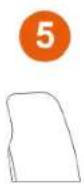
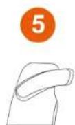
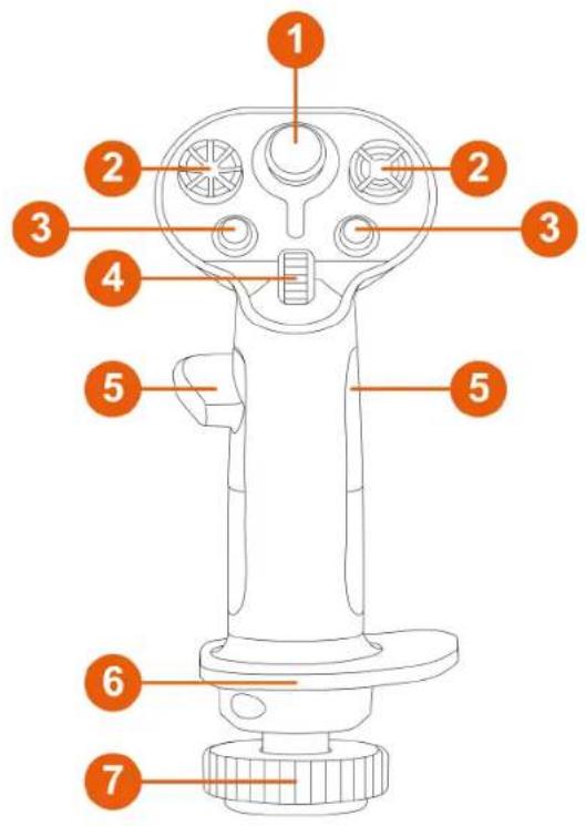
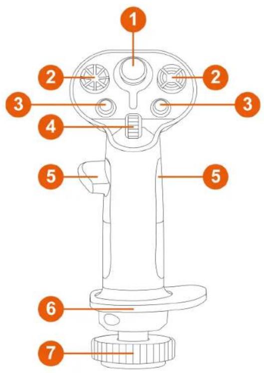
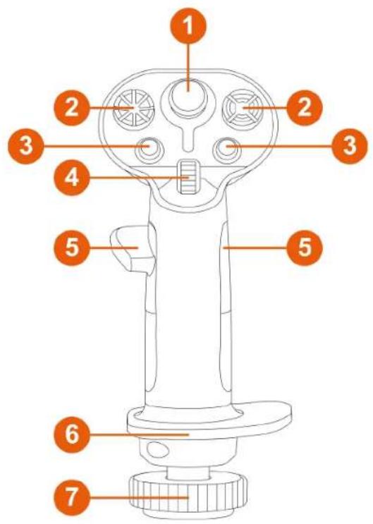
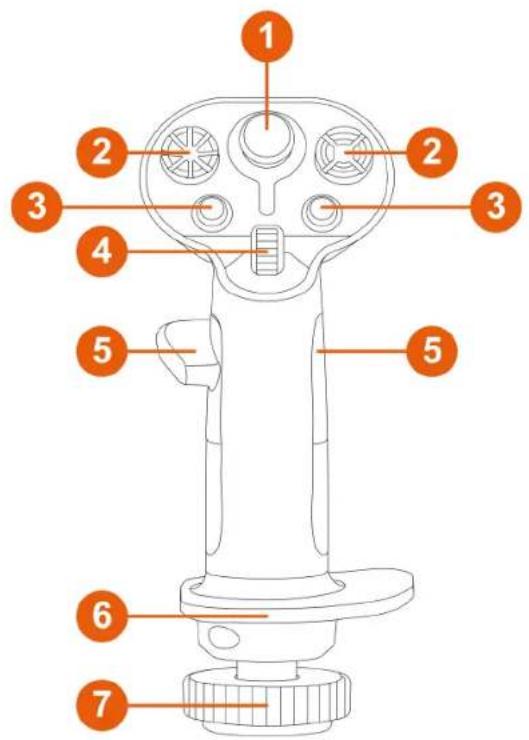
① Analog mini-stick 2 8-way multidirectional point of view hat switches ③ Action buttons 4 Scroll wheel 5 Thumb rests (right-handed and left-handed) 6 Ambidextrous wrist rest ⑦ Rudder function via rotating the flight stick grip (lockable)
11
9
10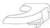
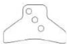
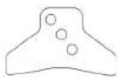
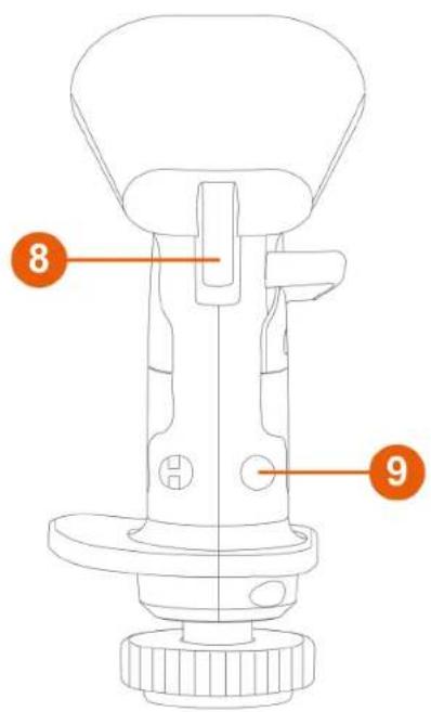
⑧ Triggers (including one dual-position trigger) 9 Removable buttons ⑩ Removable height adapter (right-handed and left-handed) 11 STAR cams (for AVA* base only)
3. Information regarding use of the flight stick grip

Documentation
Before using this product, carefully read this documentation again and keep it for future reference.

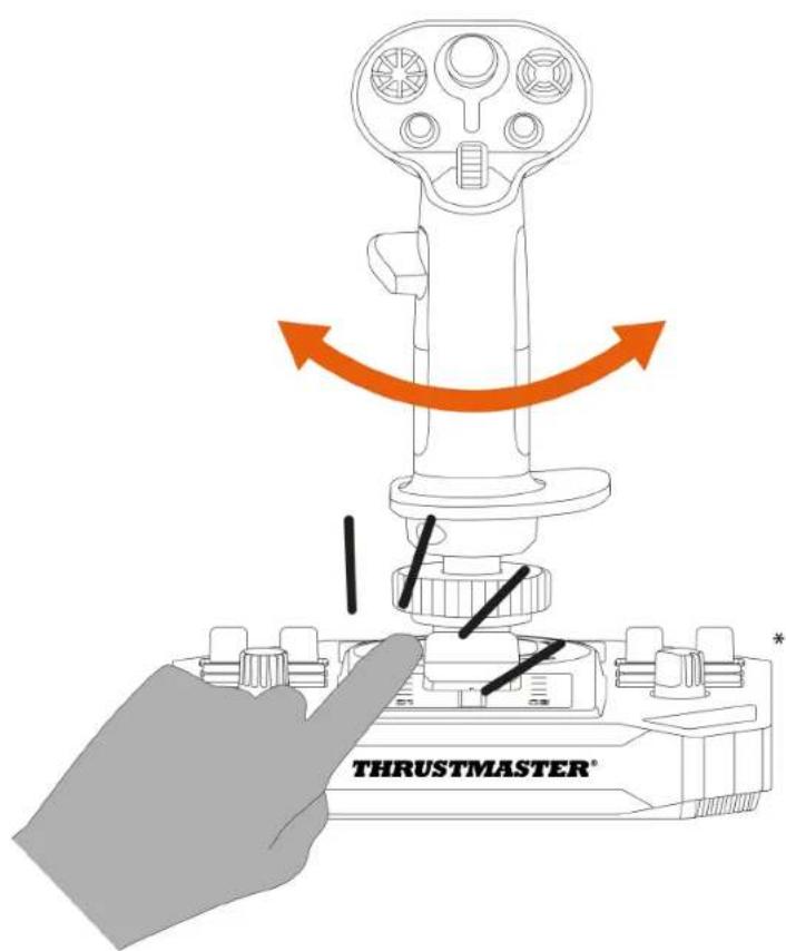
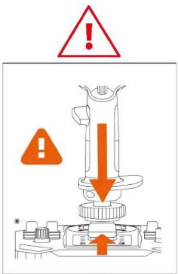
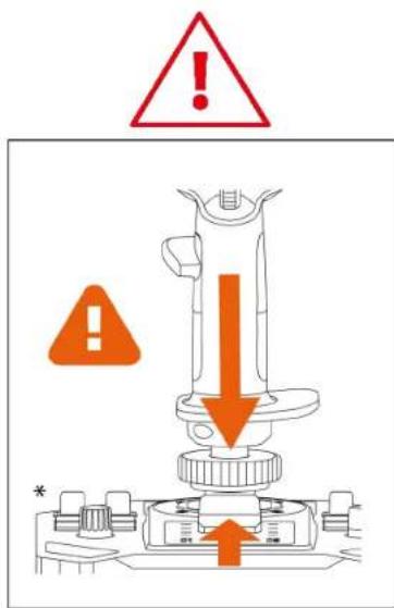
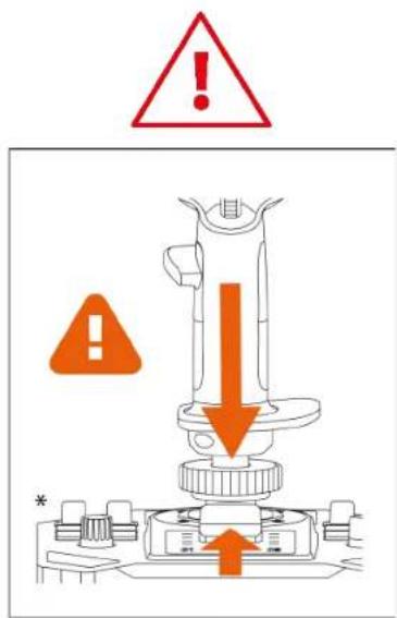
Pinch hazard
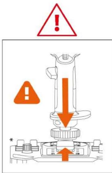
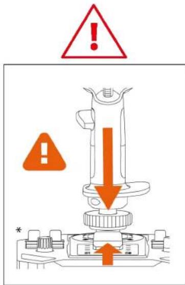
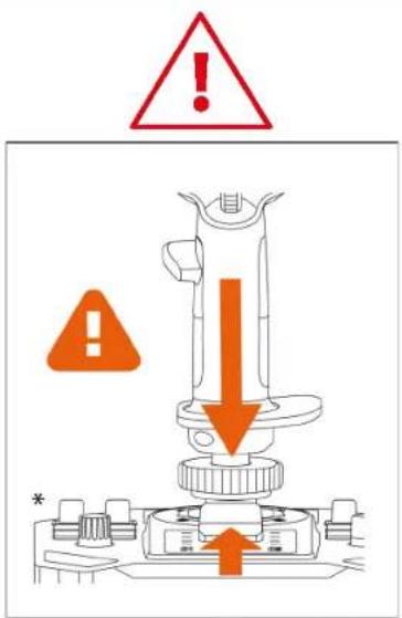
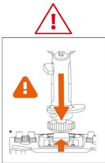
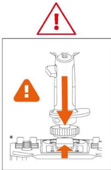
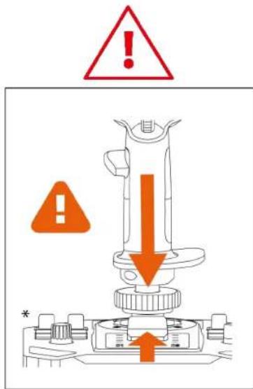
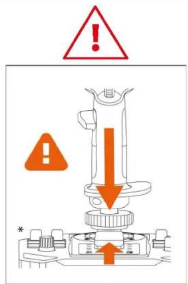
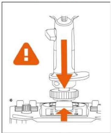
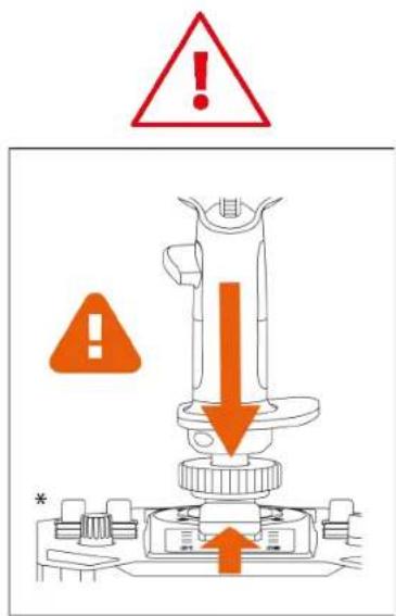
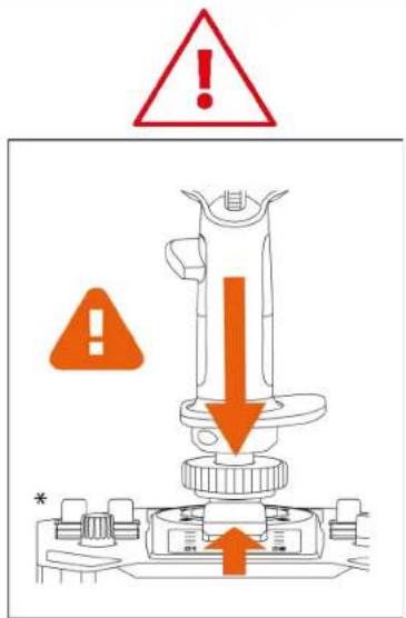
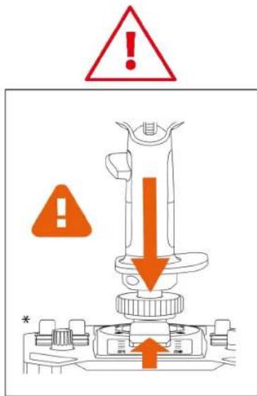
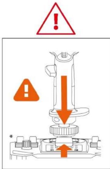
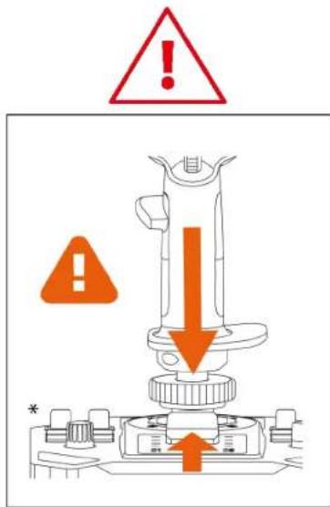
When you are using the Sol-R 3 AVA Add-On Grip flight stick grip mounted on a base*, do not place your fingers in the space between the base and the flight stick grip's axis.
4. Assembly
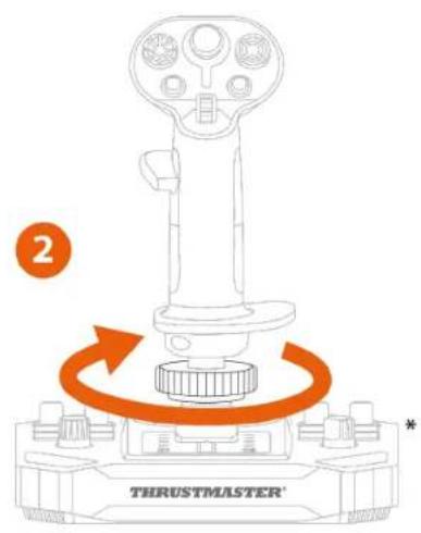
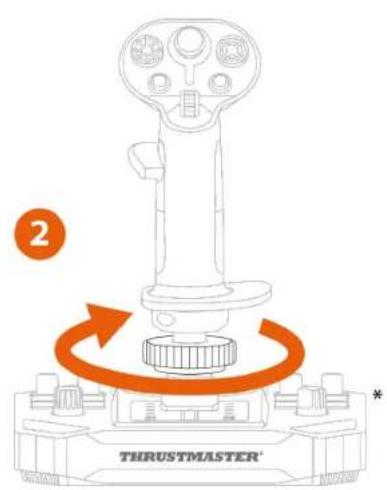
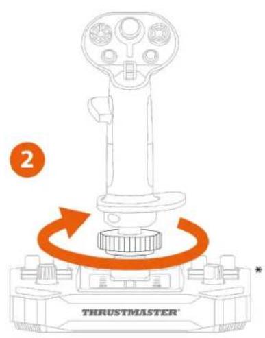
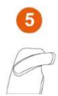
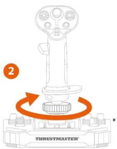
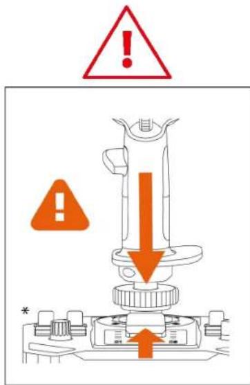
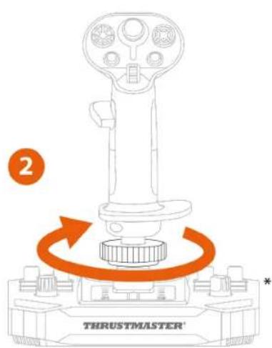
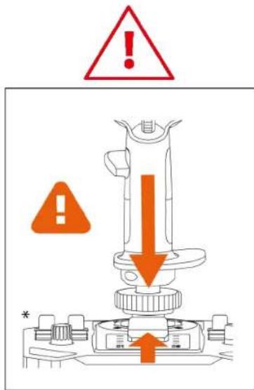
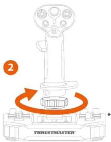
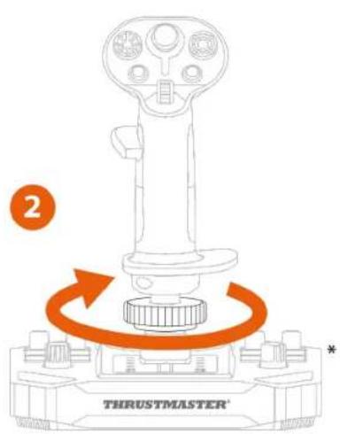
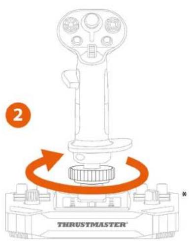
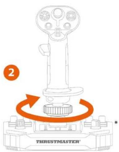
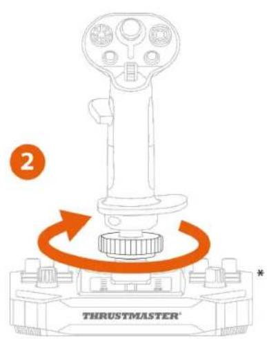
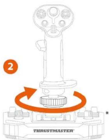
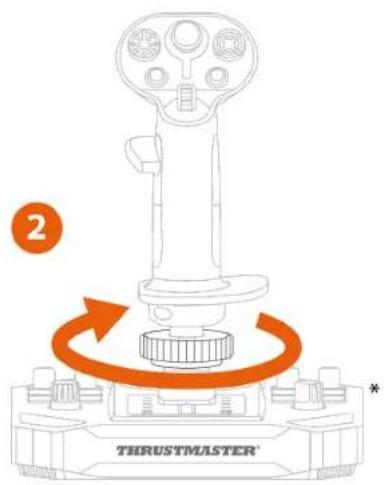
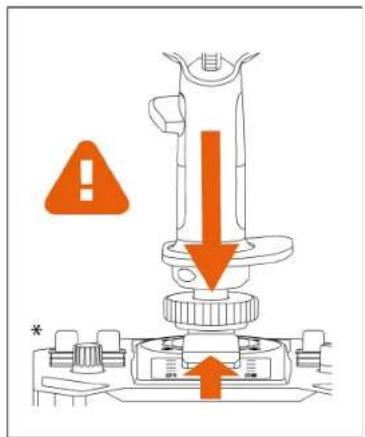
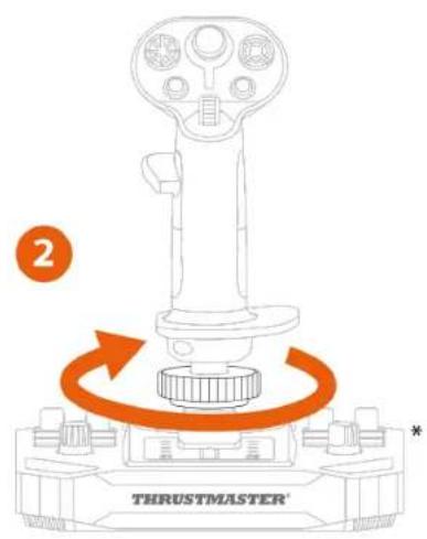
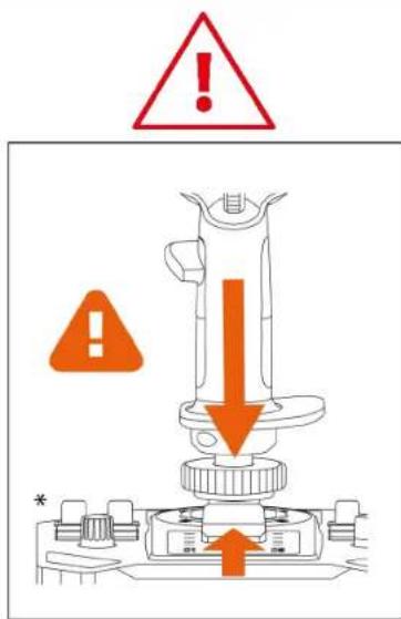
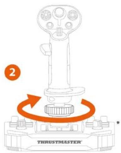
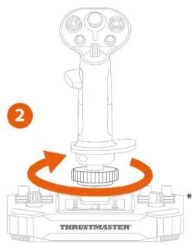
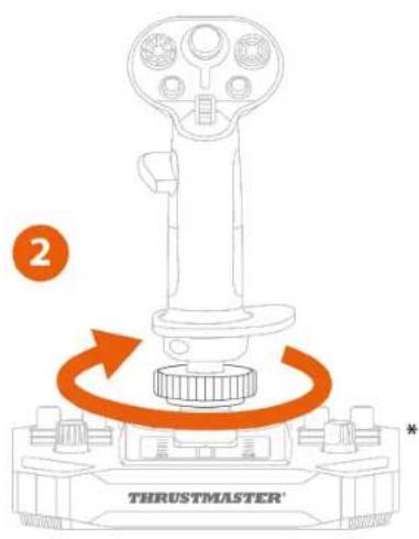
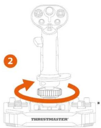
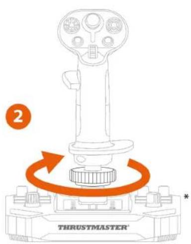
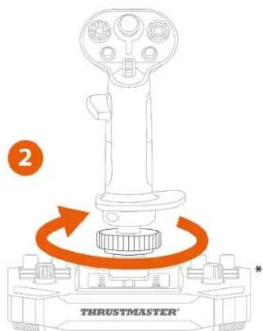
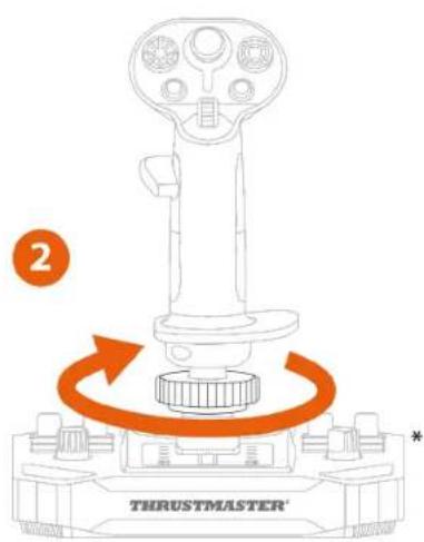
- Place the flight stick grip on a compatible base*. Make sure that the flight stick grip is properly positioned, as shown in the diagram below.
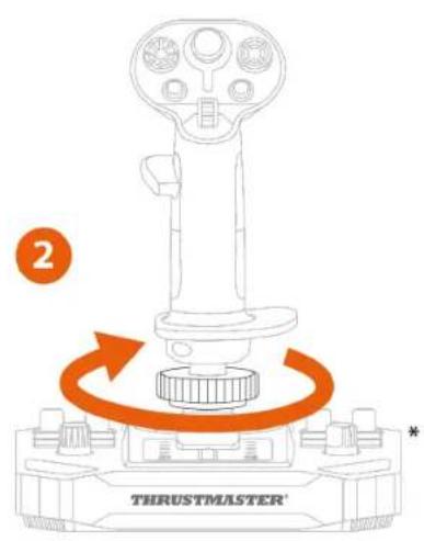
- Tighten the clamping ring.
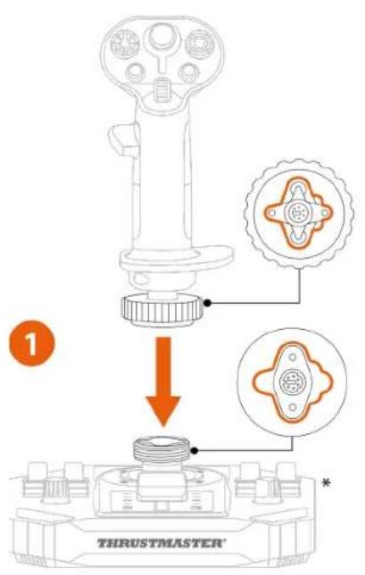
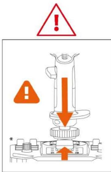
If you feel any resistance, do not force it. Make sure that the connectors for the base and the flight stick grip are properly aligned. Failure to comply with this instruction may result in damage to the products.
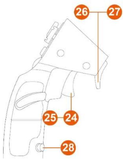
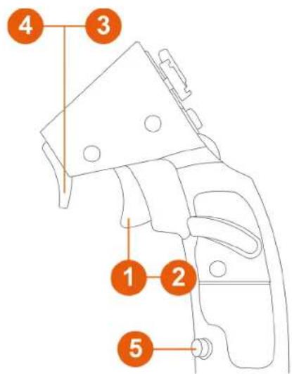
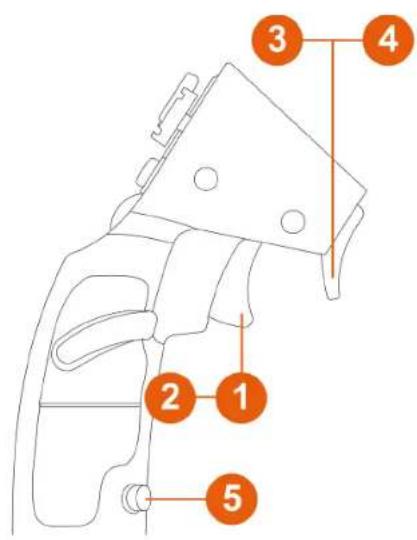
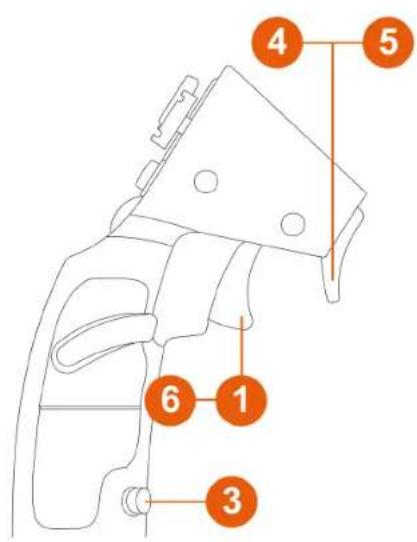
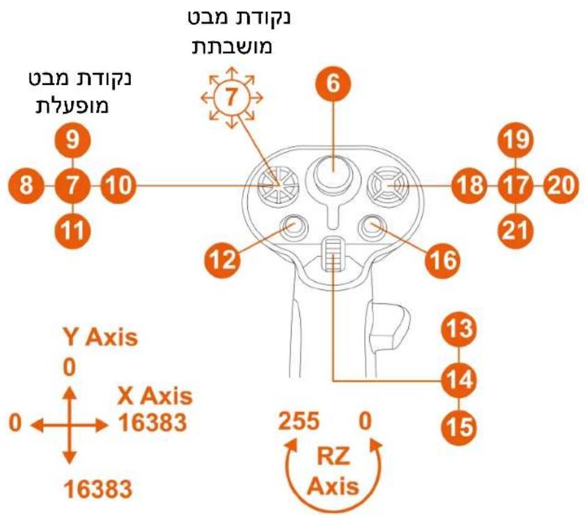
Mapping
Right-handed mode with Sol-R* base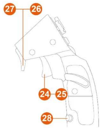
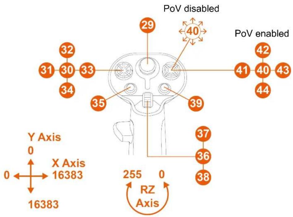
*Sold separately
Left-handed mode with Sol-R* base
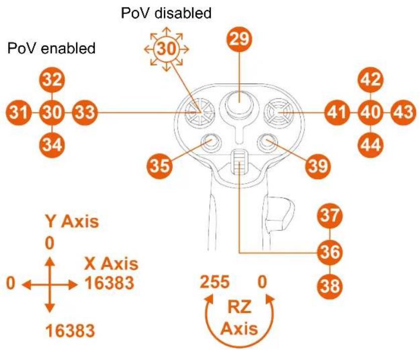
Right-handed mode with AVA* base
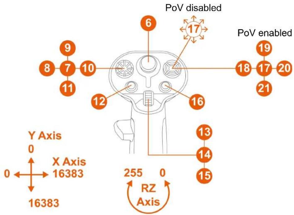
Left-handed mode with AVA* base
PoV disabled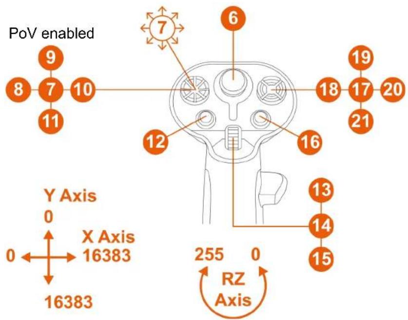
With the HOTAS Magnetic Base* base equipped with Warthog Converter*
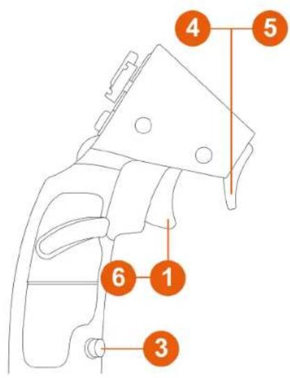
PoV disabled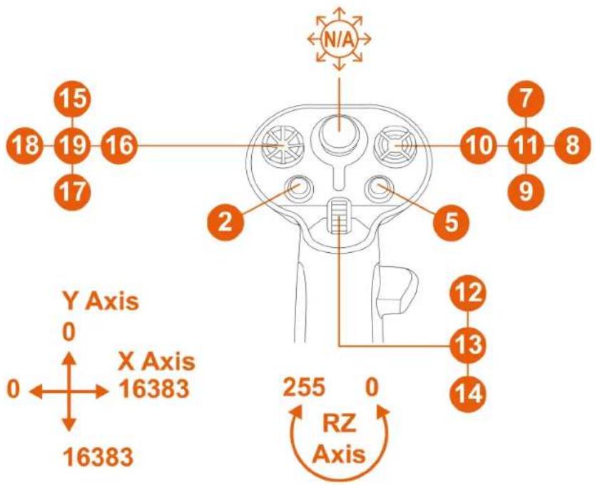

In this configuration, the flight stick grip is recognized as a VIPER HOTAS Add-On Grip.
The rudder function via rotating the flight stick grip is not functional.
Rudder function
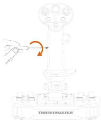
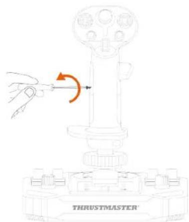
The Sol-R 3 AVA Add-On Grip flight stick grip features a rudder function that can be accessed by rotating the flight stick grip to the left or to the right.
In an airplane, the pilot manipulates the rudder to pivot the plane around its vertical axis (making the plane turn to the left or to the right).
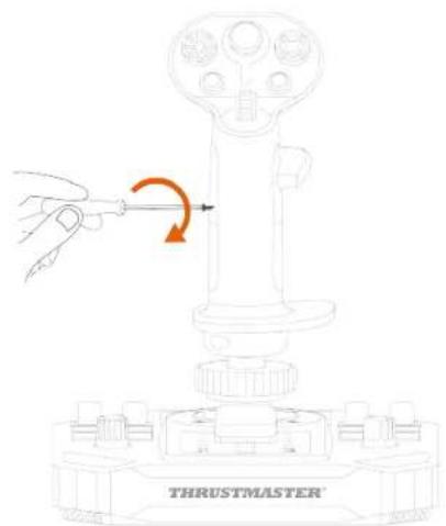
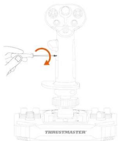
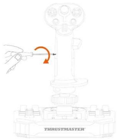
This function can be disabled by locking the rotation of the Z axis (yaw).
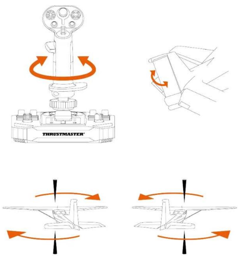
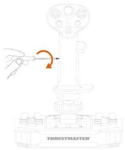
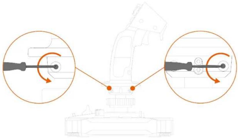
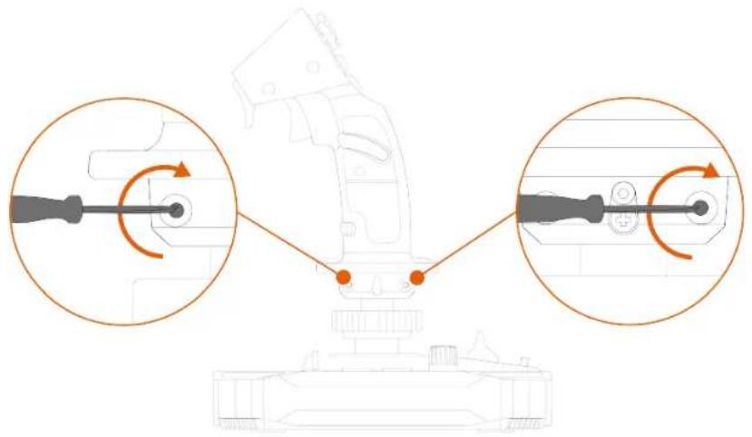
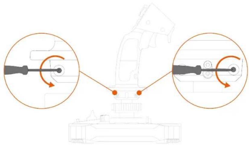
To lock the rudder function:
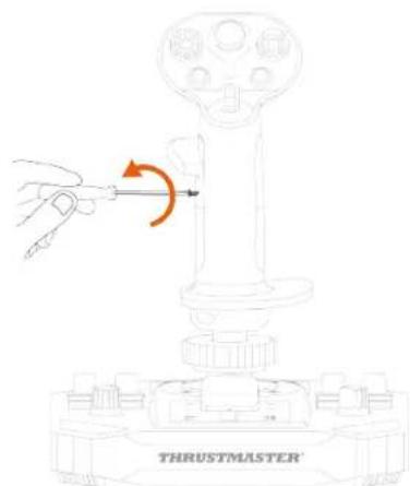
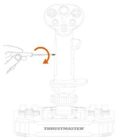
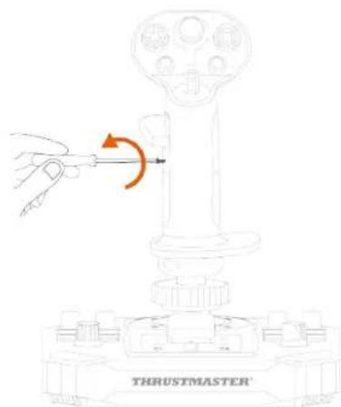
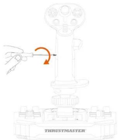
- Using a 2 mm Allen wrench (not included), tighten the hexagonal screw located below the wrist rest.
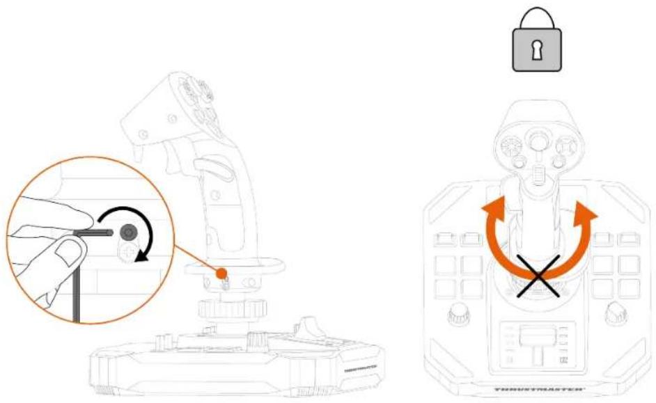
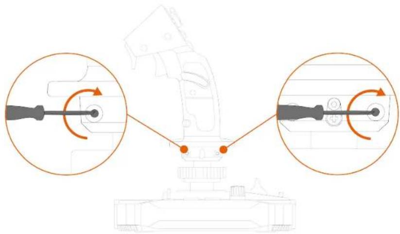
To unlock the rudder function:
- Using a 2 mm Allen wrench (not included), untighten the hexagonal screw located below the wrist rest.
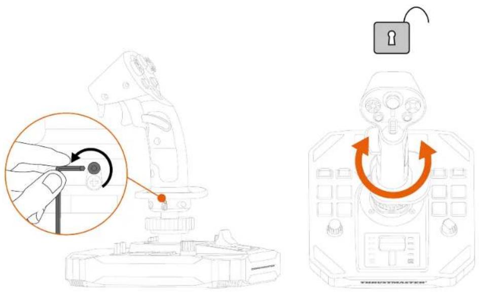
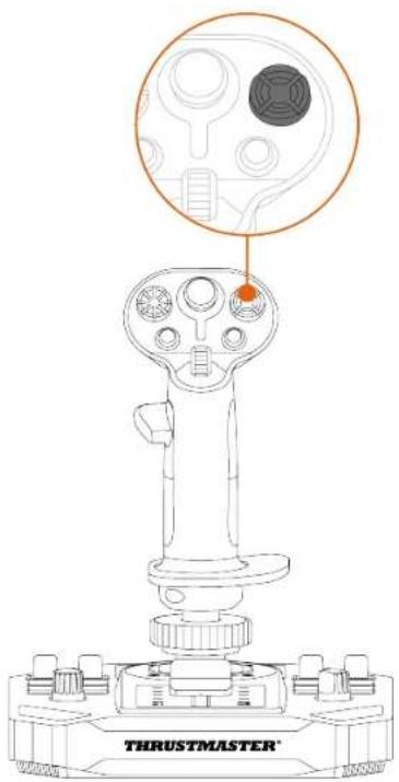
Multidirectional point of view hat switch
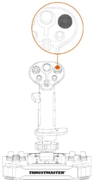
The Sol-R 3 AVA Add-On Grip flight stick grip features a multidirectional point of view hat switch that lets you monitor what's going on around your spacecraft (in games that allow this).
From your game's configuration menu, you can program the different views (rear view, left view, right view, external views) onto the directions of the multidirectional point of view hat switch.
You can also reserve the multidirectional point of view hat switch for other uses (shooting, etc.).
Left-handed mode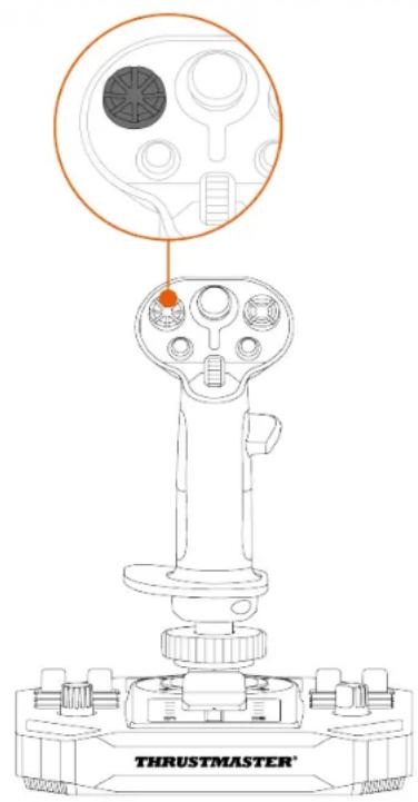
Right-handed mode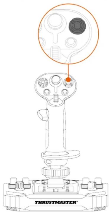
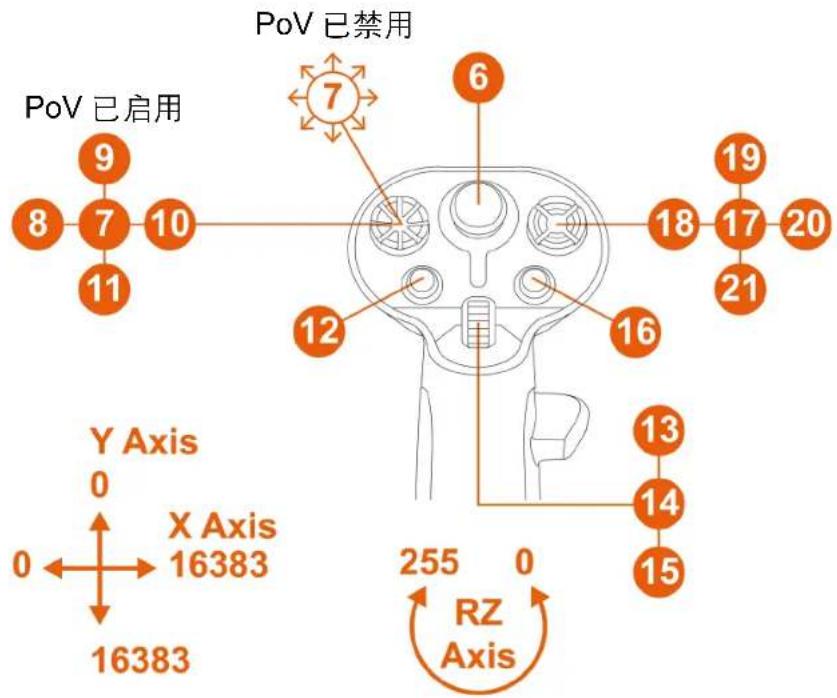
The point of view function can be disabled. However, the multidirectional hat switch can still be used.
To disable the point of view function:
- Go to the control panel for the Sol-R 3 AVA Add-On Grip flight stick grip.
- In the Game Controllers dialog box, click Properties.
- In the Test Input tab, uncheck (i.e. deselect) Point of View hat-switch.
Point of view function (Right-handed mode)
| Enabled | |
| Disabled |
Point of view function (Left-handed mode)
| Enabled | |
| Disabled |
5. Configuring the flight stick grip
Right-handed or Left-handed mode
The Sol-R 3 AVA Add-On Grip flight stick grip is ambidextrous, in order to perfectly adapt to all gamers (whether right-handed or left-handed).

By default, the flight stick grip is configured in Right-handed mode.
Example of configuration with a Sol-R* base
Left-handed mode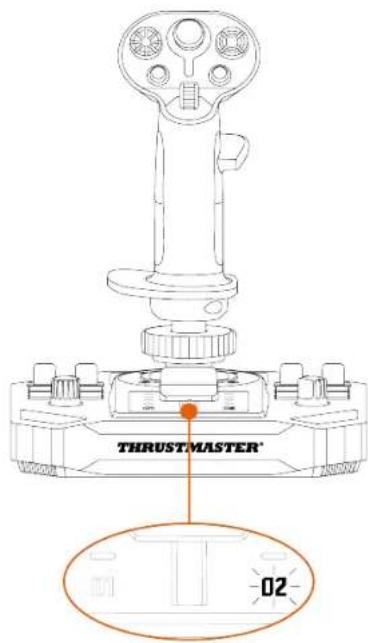
Right-handed mode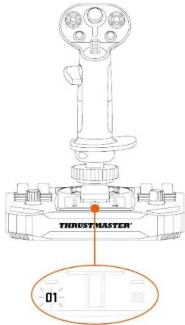

Carry out the procedure to switch from Right-handed to Left-handed mode (or vice versa) before connecting the joystick to your PC.
To set the joystick in Left-handed mode:
- Set the selector switch located on the underside of the joystick's base to LEFT HANDED.
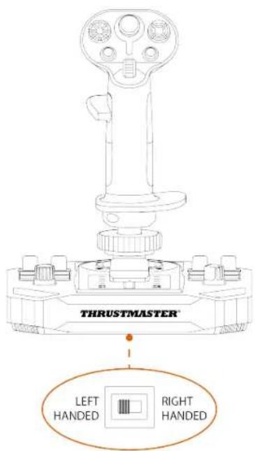

The joystick is recognized with the name Sol-R [L] Flightstick.
To set the joystick in Right-handed mode:
- Set the selector switch located on the underside of the joystick's base to RIGHT HANDED.
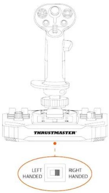

The joystick is recognized with the name Sol-R [R] Flightstick.
Example of configuration with an AVA* base or a HOTAS Magnetic Base* base
When the Sol-R 3 AVA Add-On Grip flight stick grip is installed on an AVA* base or a HOTAS Magnetic Base* base:
- Go to the control panel.
- In the Game Controllers dialog box, click Properties.
- In the Test Input tab, select RIGHT-HANDED or LEFT-HANDED.
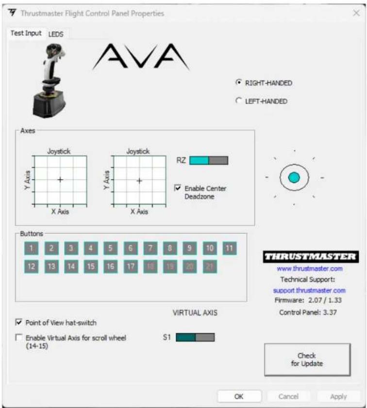
*Sold separately
Changing from Right-handed mode to Left-handed mode
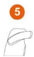
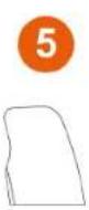
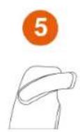
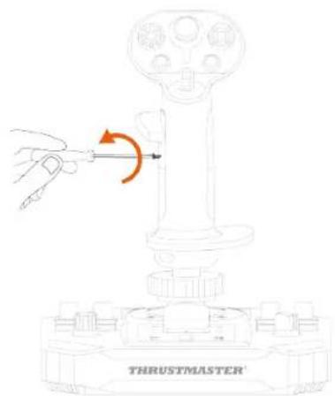
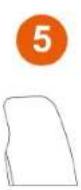
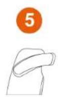
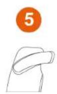
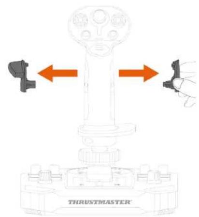
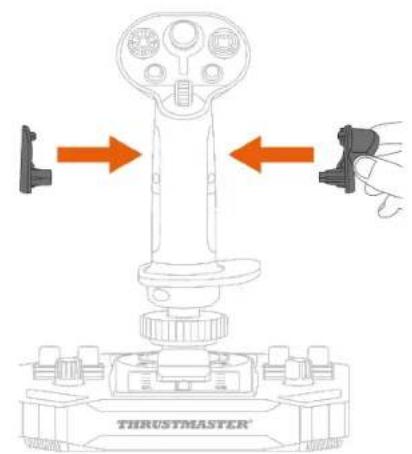
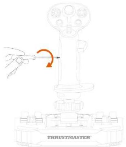
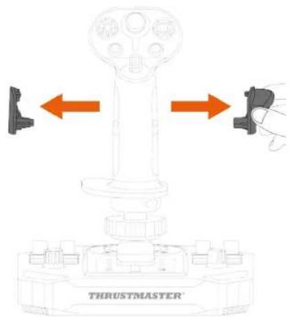
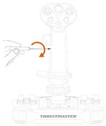
- Unscrew the right-hand thumb rest.
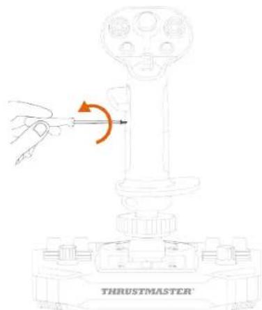
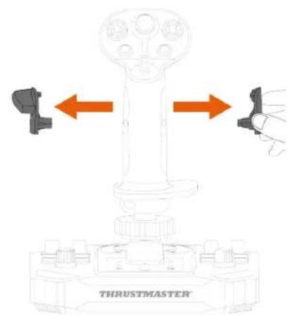
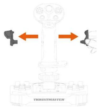
- Remove both parts of the right-hand thumb rest.
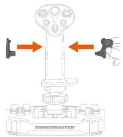
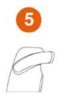
- Place both parts of the left-hand thumb rest on the flight stick grip.
- Screw in the left-hand thumb rest.
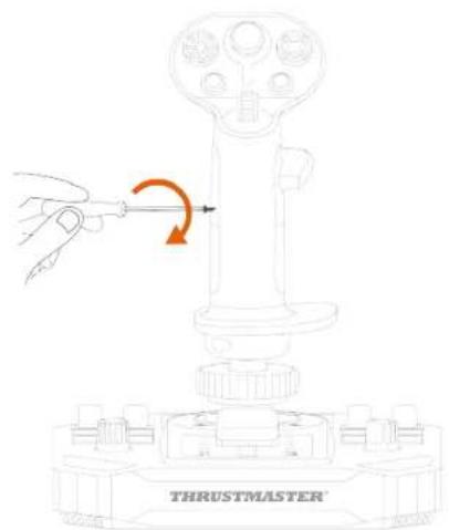
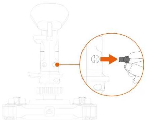
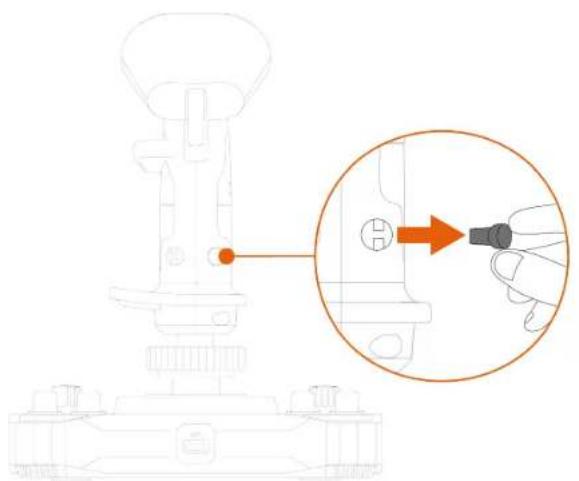
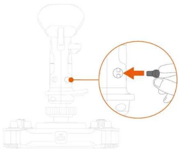
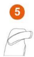
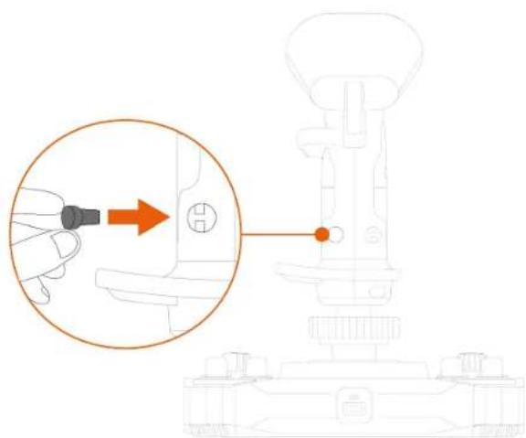
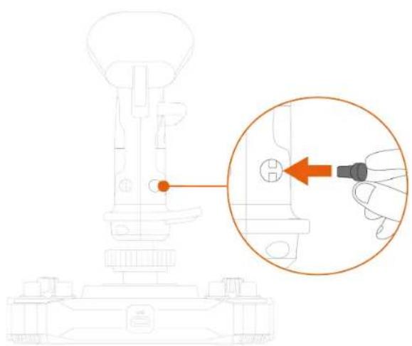
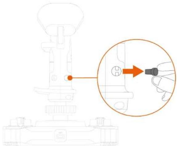
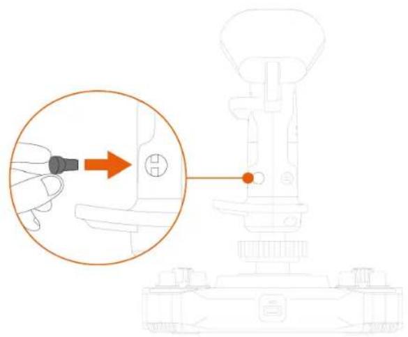
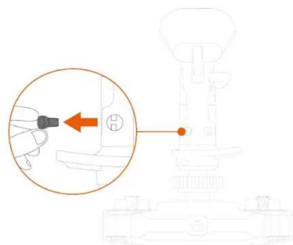
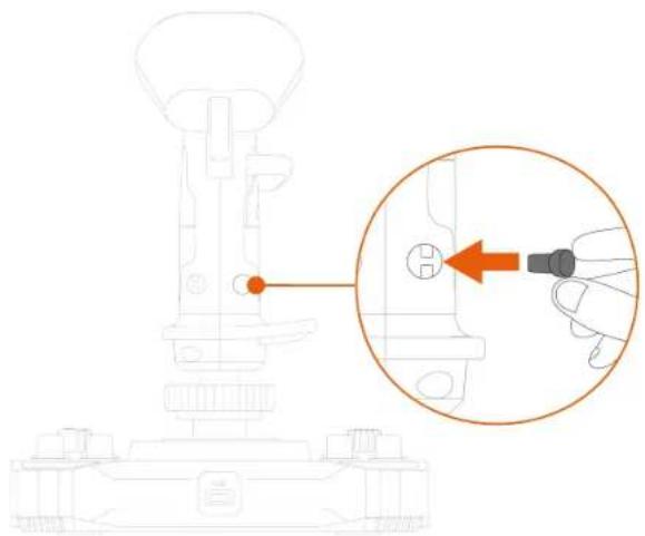
- Remove the removable button located on the back of the flight stick grip.

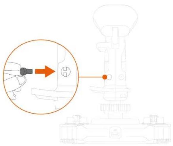
- Insert the removable button below the thumb rest.
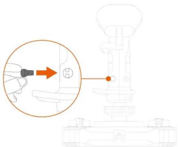
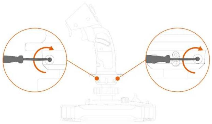
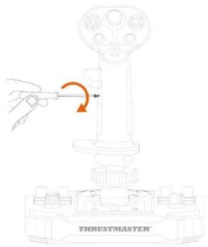
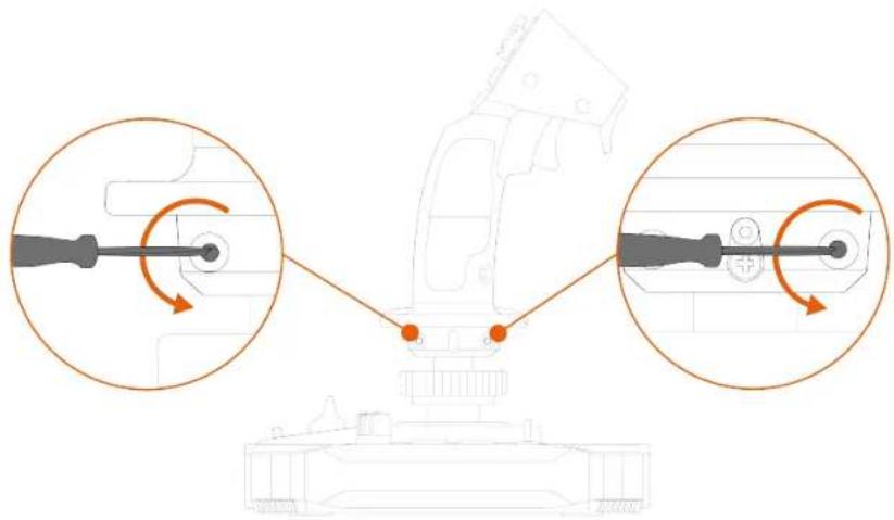
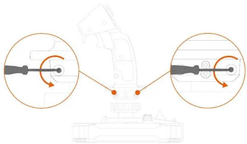
- Unscrew the two screws holding the wrist rest in place.
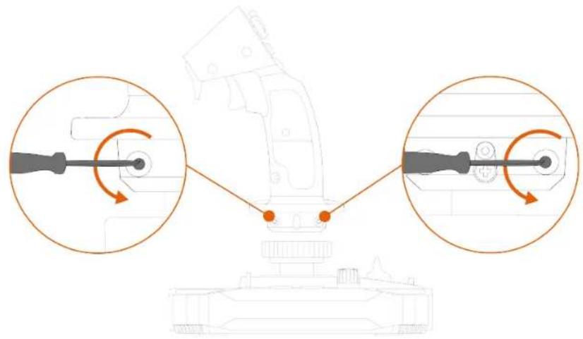
- Remove the two parts of the wrist rest, and then reposition them on the flight stick grip by reversing the parts.
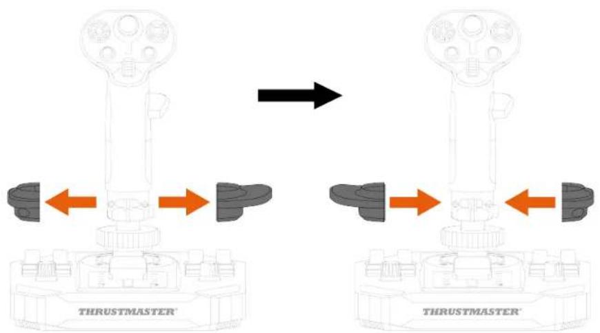
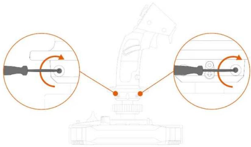
- Screw in the two screws that hold the wrist rest in place.
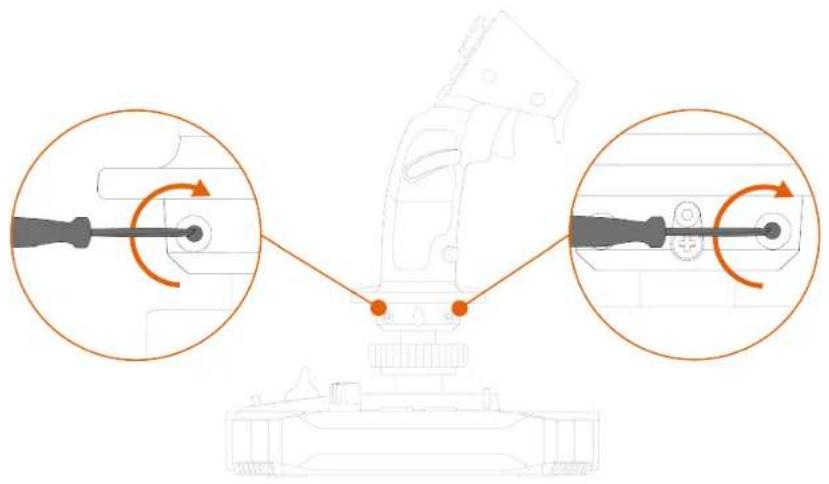
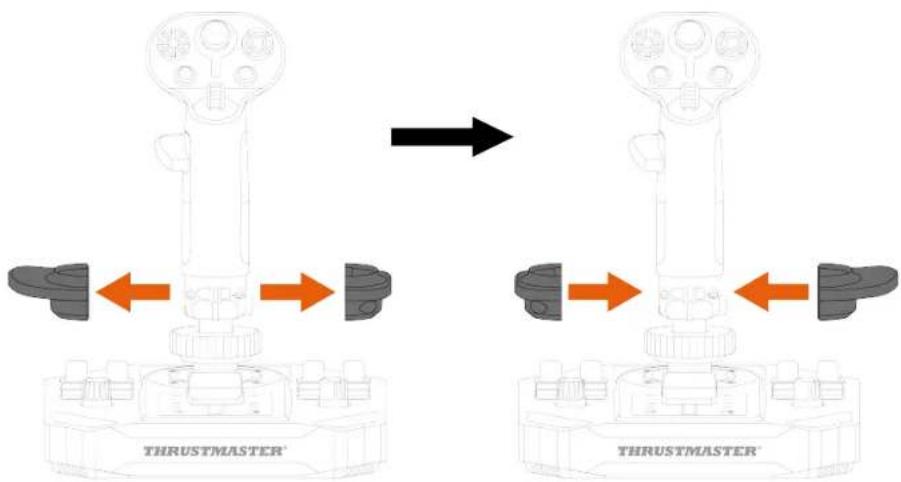
Changing from Left-handed mode to Right-handed mode
- Unscrew the left-hand thumb rest.
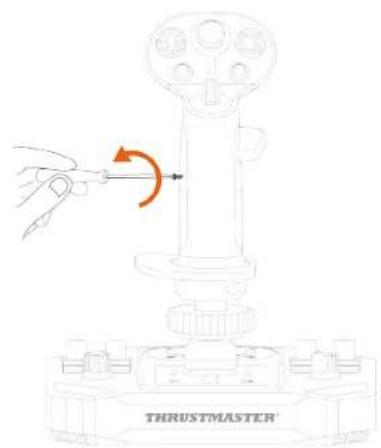
- Remove both parts of the left-hand thumb rest.
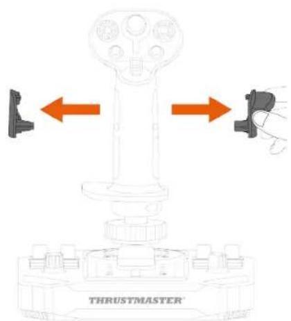
- Place both parts of the right-hand thumb rest on the flight stick grip.
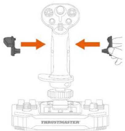
- Screw in the right-hand thumb rest.
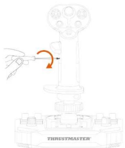
- Remove the removable button located on the back of the flight stick grip.
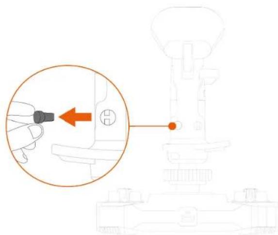
- Insert the removable button below the thumb rest.
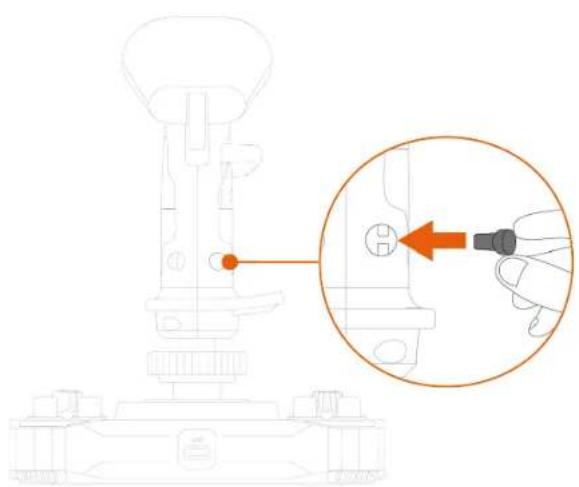
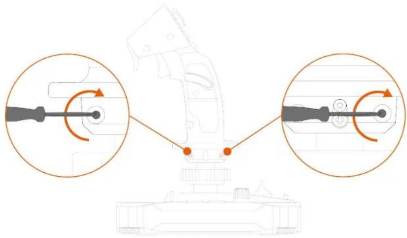
- Unscrew the two screws holding the wrist rest in place.
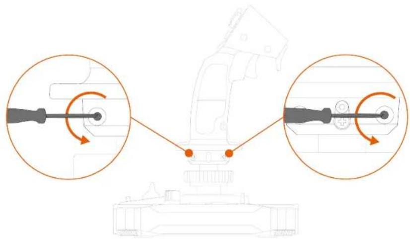
- Remove the two parts of the wrist rest, and then reposition them on the flight stick grip by reversing the parts.
- Screw in the two screws that hold the wrist rest in place.
Height adapter
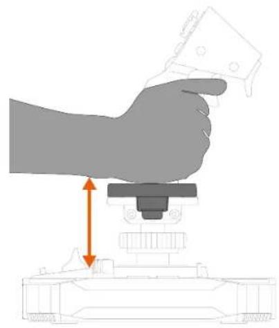
The Sol-R 3 AVA Add-On Grip flight stick grip features a height adapter to raise your hand when you're holding the flight stick grip, for greater comfort.
Without the adapter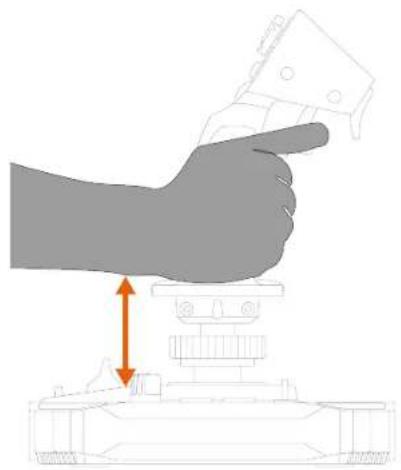
With the adapter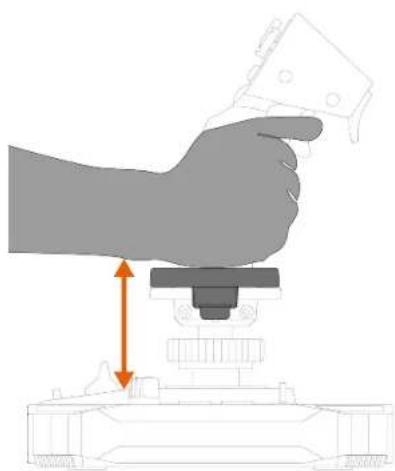
To install the height adapter, clip it to the wrist rest.
Left-handed mode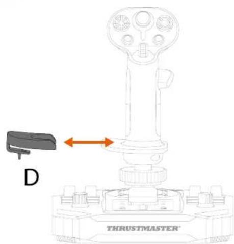
Right-handed mode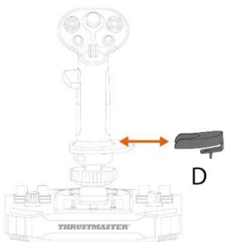
6. Compatibility

Be sure to only use authorized accessories. The use of unauthorized accessories may damage the product and void the warranty.
Bases
The Sol-R 3 AVA Add-On Grip flight stick grip is compatible with the AVA* base, the Sol-R 5 Base* base and the HOTAS Magnetic Base* base.
![graph TD A["Sensor"] --> B["WARTHOG CONVERTER"] B --> C["AVA"] B --> D["SOL-R5 BASE"] B --> E["HOTAS MAGNETIC BASE"] C --> F["*"] D --> G["*"] E --> H["*"]](/content/2026/04/740509/images/f45e49301a700cd919c737c6606f2f615d1294fcb2103769c2c6d8d0390123e0.jpg)

Installing the Sol-R 3 AVA Add-On Grip flight stick grip on a HOTAS Magnetic Base* base requires the use of Warthog Converter* in order to ensure compatibility.
Cams
The Sol-R 3 AVA Add-On Grip flight stick grip comes with two STAR cams for AVA* base owners to use in space simulation.

The cams adjust the way in which the force applied to the flight stick grip is transformed into movement, changing the feel of the flight stick grip's trajectory, along with its behavior.
The procedure for installing cams on an AVA* base is available here:
https://support.thrustmaster.com/product/ava/
7. T.A.R.G.E.T
advanced
programming software

T.A.R.G.E.T (Thrustmaster Advanced pRogramming Graphical EdiTor) is an innovative, high-performance software suite allowing for improvements to most Thrustmaster flight controllers, and the sharing of profiles with the Thrustmaster community.
Installation
- Please visit:
https://support.thrustmaster.com/product/sol-r-3-ava-add-on-grip
- In the Software section, download and install the T.A.R.G.E.T advanced programming software.
Main features
- Various possible configurations of the axes.
- Multiple programming levels available: Basic, Advanced and Script.
- Use of the Drag and Drop principle.
- Ability to merge the Sol-R 3 AVA Add-On Grip flight stick grip with other Thrustmaster flight simulation accessories (Hotas Cougar*, T.16000M FCS*, TWCS*, TFRP*, MFD Cougar Pack*, TCA range*, VIPER range*, AVA range*, Sol-R range* — all of which are also compatible with T.A.R.G.E.T), allowing for them to be recognized as a single USB device.
- Access to advanced profiles created by the Thrustmaster community.
8. FAQ and technical support
Do you have questions regarding the Sol-R 3 AVA Add-On Grip flight stick grip, or are you experiencing technical problems? If so, visit the Thrustmaster technical support website:
https://support.thrustmaster.com/product/sol-r-3-ava-add-on-grip

1. My joystick isn't working properly, or seems to be improperly calibrated
- Power off your PC, disconnect your joystick and then reconnect it, restart your PC and start up your game again.
- When connecting your joystick, be sure to keep the flight stick grip centered and avoid moving it, to avoid any calibration problems.
2. I can't configure my joystick
- Access your game's menu and select Options > Controller > Gamepad or Joystick. Then choose the most appropriate configuration, or completely reconfigure the joystick's options.
- For more information, please refer to your game's user manual or online help.
3. My joystick is too sensitive, or not sensitive enough
- The joystick automatically self-calibrates after a few movements on the different axes.
- Access your game's menu and select Options > Controller > Gamepad or Joystick. Then adjust your joystick's sensitivity and dead zones if these options are available.
4. My joystick isn't working
In order for the joystick to work properly with video games, you need to update the base's firmware.
- If you are using a Sol-R 5 Base base, please visit https://support.thrustmaster.com/product/sol-r-5-base
- If you are using an AVA base, please visit https://support.thrustmaster.com/product/ava
- If you are using a HOTAS Magnetic Base base, please visit https://support.thrustmaster.com/product/hotas-magnetic-base
Select Drivers and follow the instructions, including the downloading and installation procedure.
THRUSTMASTER®
For PC (Windows® 10/11)
https://support.thrustmaster.com/product/hotas-magnetic-base
4. Assembly
*sold separately
Right-handed mode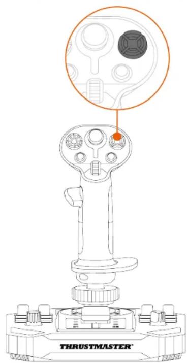
With the adapter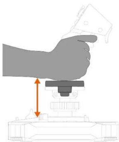
Right-handed mode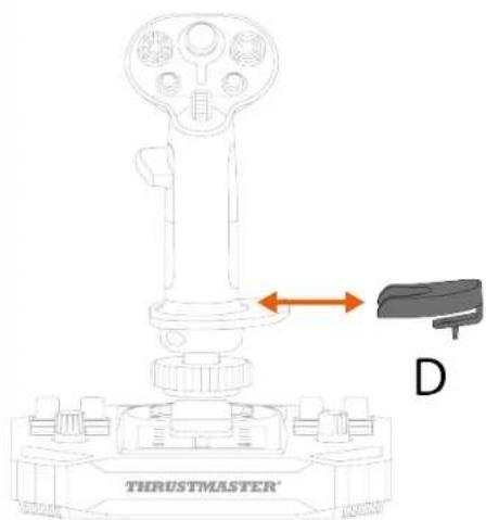
6. Compatibility

https://support.thrustmaster.com/product/ava/
https://support.thrustmaster.com/product/sol-r-3-ava-add-on-grip/.
https://support.thrustmaster.com/product/hotas-magnetic-base
PC (Windows® 10/11)
User manual

- https://support.thrustmaster.com/product/ava
https://support.thrustmaster.com/product/hotas-magnetic-base
4. Assembly
Multidirectional point-of-view
Switch
Right-handed mode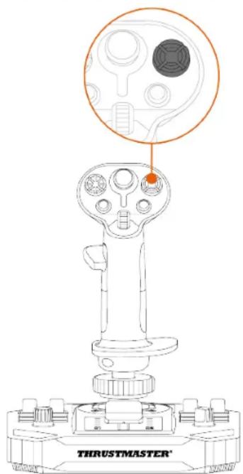

Height adapter
With adapter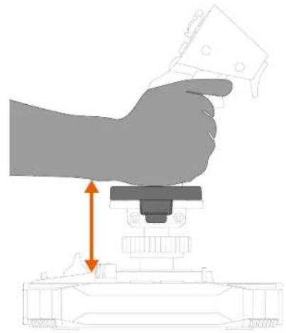
Right-handed mode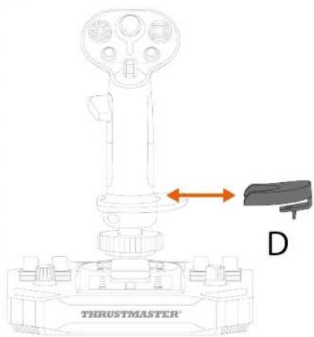
6. Compatibility

https://support.thrustmaster.com/product/ava/
PROGRAMMING SOFTWARE....41
Installation 41
2. Technical specifications
4. Assembly
Multidirectional
Point-of-View hat
switch
Right-handed mode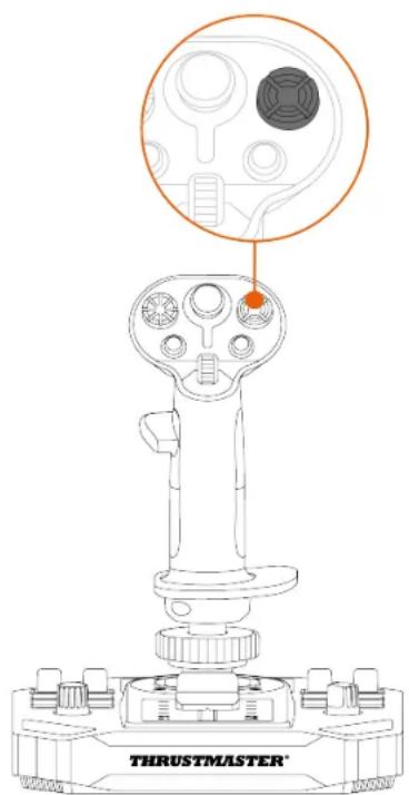
- Tighten the left thumb rest screw.
- Tighten the right thumb rest screw.
Height adapter
With the adapter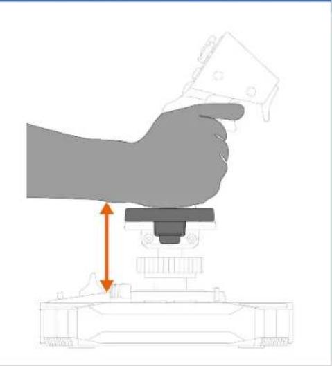
Right-handed mode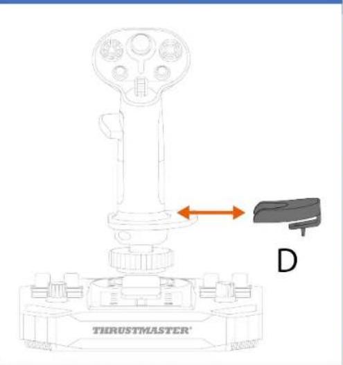
6. Compatibility

https://support.thrustmaster.com/product/ava/
7. T.A.R.G.E.T
advanced
programming software

https://support.thrustmaster.com/product/hotas-magnetic-base
PC (Windows® 10/11)
User manual

4. Assembly
Right-handed mode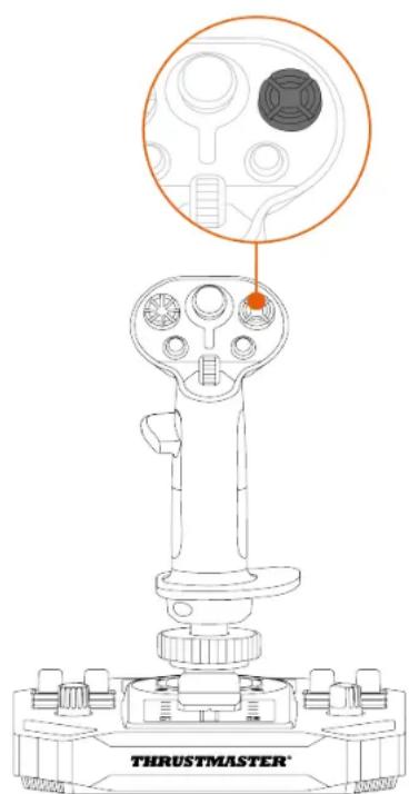
https://support.thrustmaster.com/product/ava/
https://support.thrustmaster.com/product/sol-r-5-base
https://support.thrustmaster.com/product/hotas-magnetic-base
4. Assembly
Right-handed mode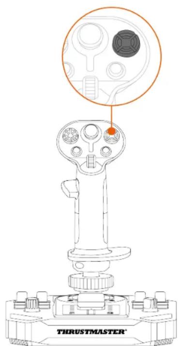
Height adapter
With the adapter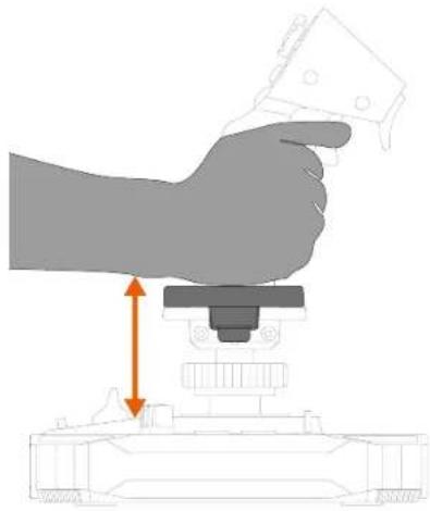
Right-handed mode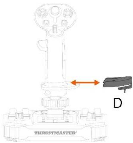
6. Compatibility

https://support.thrustmaster.com/product/ava/
PC (Windows® 10/11)
User Manual

4. Assembly
Multidirectional point-of-view hat switch
multidirectional
Right-handed mode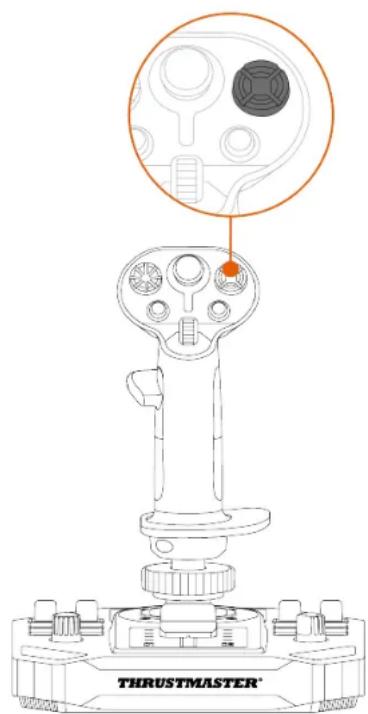

* Sold separately
- Screw in the left thumb rest.
Height adapter
With the adapter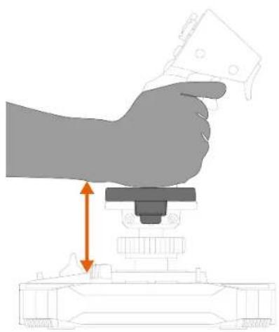
Right-handed mode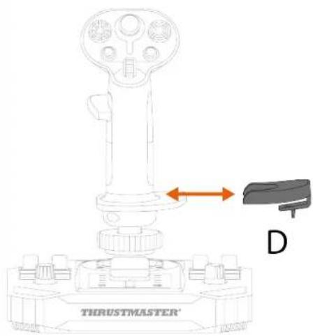
6. Compatibility

https://support.thrustmaster.com/product/ava/.
https://support.thrustmaster.com/product/sol-r-3-ava-add-on-grip.
https://support.thrustmaster.com/product/sol-r-3-ava-add-on-grip.
https://support.thrustmaster.com/product/hotas-magnetic-base.
PC (Windows® 10/11)
4. Assembly

Height adapter
With the adapter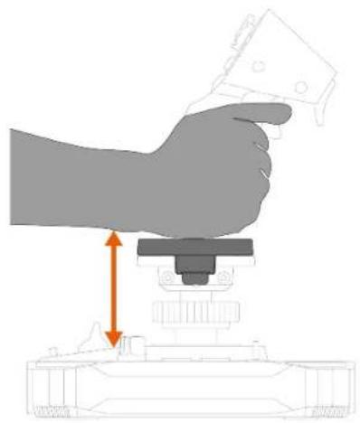
6. Compatibility

https://support.thrustmaster.com/product/ava/
https://support.thrustmaster.com/product/sol-r-3-ava-add-on-grip
PC (Windows® 10/11)
User Manual

4. Mounting
Right-handed mode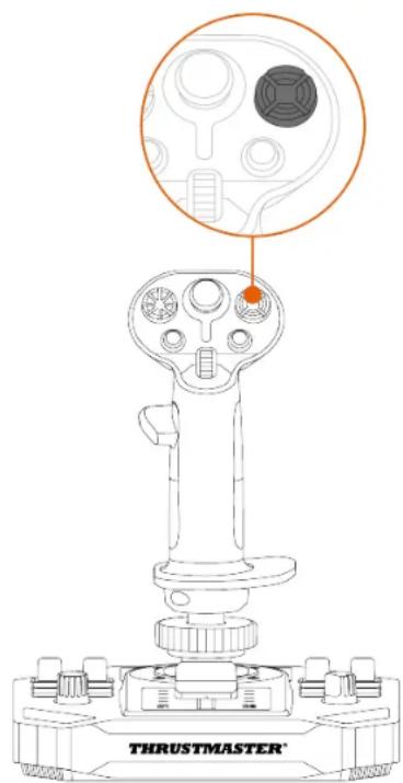
Height adapter
https://support.thrustmaster.com/product/ava/
7. T.A.R.G.E.T
advanced
https://support.thrustmaster.com/product/sol-r-5-base
https://support.thrustmaster.com/product/hotas-magnetic-base
https://support.thrustmaster.com/product/sol-r-5-base
https://support.thrustmaster.com/product/ava
https://support.thrustmaster.com/product/hotas-magnetic-base
4. Installation
Height adapter
https://support.thrustmaster.com/product/ava/
https://support.thrustmaster.com/product/sol-r-5-base
https://support.thrustmaster.com/product/ava
https://support.thrustmaster.com/product/hotas-magnetic-base
4. Installation

* Sold separately
Height adapter
With adapter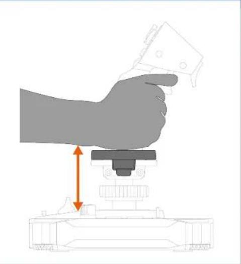
Right-handed mode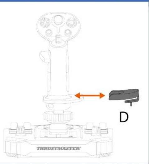
6. Compatibility

https://support.thrustmaster.com/product/ava/
https://support.thrustmaster.com/product/sol-r-5-base
https://support.thrustmaster.com/product/ava
https://support.thrustmaster.com/product/hotas-magnetic-base
https://support.thrustmaster.com/product/sol-r-5-base
https://support.thrustmaster.com/product/ava
- If you have a Thrustmaster HOTAS Magnetic Base
Visit
https://support.thrustmaster.com/product/hotas-magnetic-base
5
5
1
4. Assembly
* Separate screws
.4. Visit
.5
Flight.


(Thrustmaster Advanced Programming Graphical
https://support.thrustmaster.com/product/sol-r-3-ava-add-on-grip
https://support.thrustmaster.com/product/sol-r-3-
ava-add-on-grip
https://support.thrustmaster.com/product/sol-r-5-
base
https://support.thrustmaster.com/product/ava
https://support.thrustmaster.com/product/hotas-
magnetic-base
PC (Windows® 10/11)
User's Manual

https://support.thrustmaster.com/product/sol-r-5-base
https://support.thrustmaster.com/product/ava
https://support.thrustmaster.com/product/hotas-magnetic-base
2. Technical Specifications
*Optional accessories
4. Assembly
*Optional accessories

To unlock the ladder function:
Multi-directional view hat switch
Right-handed mode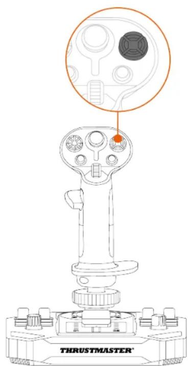
*Optional accessories
Changing from right-handed mode to left-handed mode
- Remove the screw of the right-handed thumb rest.
- Secure the screw of the left-handed thumb rest.
Changing from left-handed mode to right-handed mode
- Remove the screw of the left-handed thumb rest.
- Secure the screw of the right-handed thumb rest.
Height adapter

6. Interchangeability

https://support.thrustmaster.com/product/ava/
https://support.thrustmaster.com/product/sol-r-5-base
https://support.thrustmaster.com/product/hotas-magnetic-base
2. Technical Specifications
*Sold separately
4. Assembly
*Sold separately
*Sold separately
To unlock the rudder function, please:
Multi-directional view hat switch
*Sold separately
To switch from right-handed mode to left-handed mode
- Loosen the right-hand thumb rest.
- Remove the two parts of the right-hand thumb rest.
- Place the two parts of the left palm rest on the flight stick.
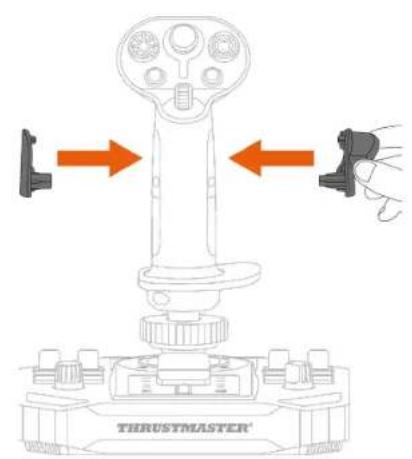
- Tighten the left thumb rest.
- Remove the detachable button located on the back of the flight stick.
- Insert the detachable button below the thumb rest.
- Loosen the two screws that secure the wrist rest.
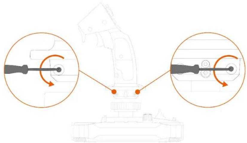
- Tighten the two screws that secure the wrist rest.
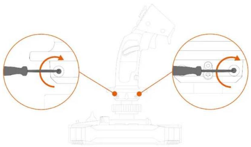
Switch from left-handed mode to right-handed mode
- Loosen the left thumb rest.
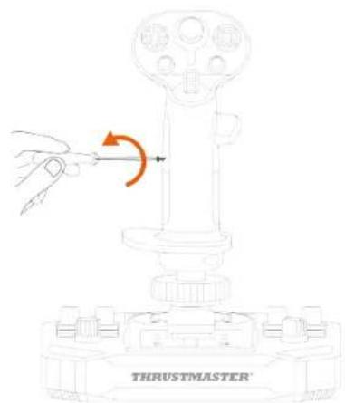
- Remove the two parts of the left thumb rest.
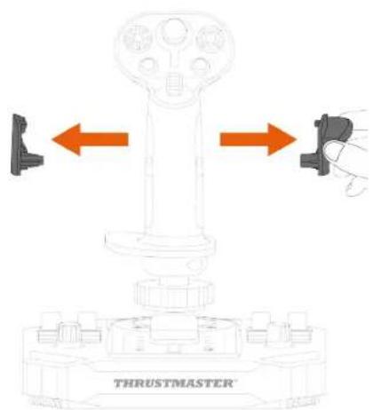
- Place the two parts of the right palm rest on the flight stick.
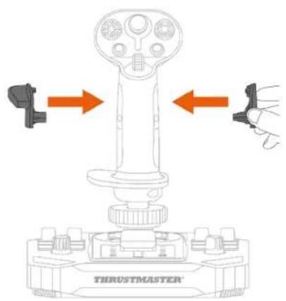
- Tighten the right thumb rest.
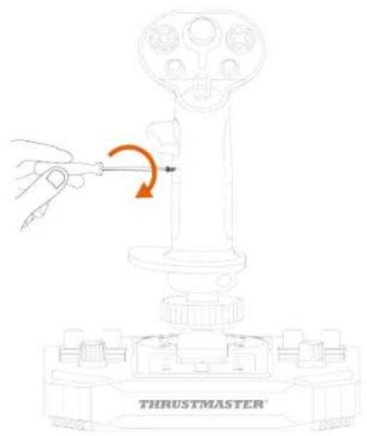
- Remove the detachable button located on the back of the flight stick.
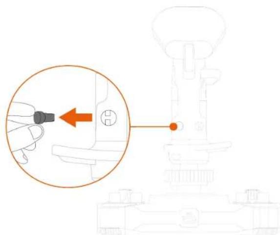
- Insert the detachable button below the thumb rest.
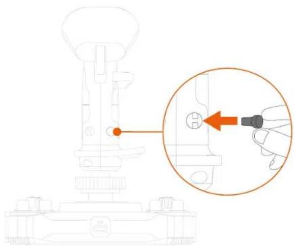
- Loosen the two screws that secure the wrist rest.
- Tighten the two screws that secure the wrist rest.
Height adapter
PC (Windows® 10/11)
User manual

https://support.thrustmaster.com/product/hotas-magnetic-base
2. Technical specifications
5
5
*Sold separately
4. Assembly
*Sold separately
To unlock the rudder function, please:
Multi-directional view hat switch
*Sold separately
Change from right-handed mode to left-handed mode
- Loosen the right thumb rest.
- Remove the two parts of the right thumb rest.
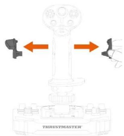
- Place the two parts of the left palm rest on the flight handle.
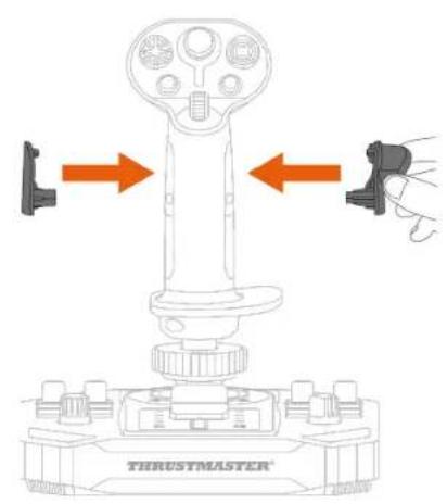
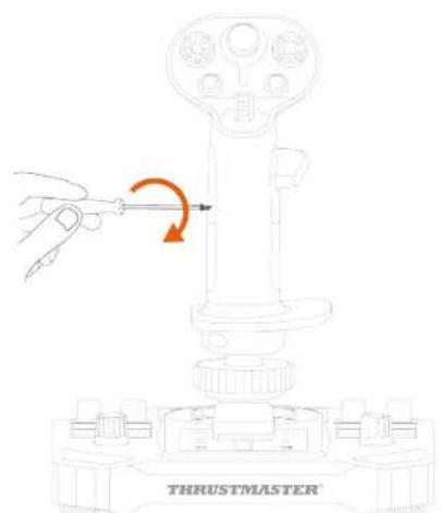
- Tighten the left thumb rest.
- Remove the detachable button located on the back of the flight handle.
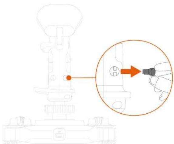
- Insert the detachable button below the thumb rest.
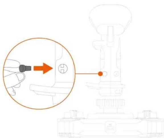
- Loosen the two screws that secure the wrist rest.
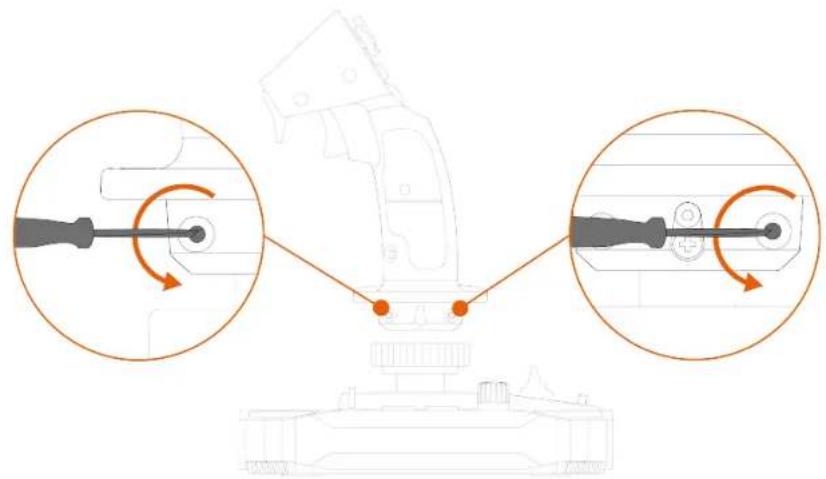
- Tighten the two screws that secure the wrist rest.
Change from left-handed mode to right-handed mode.
- Loosen the left thumb rest.
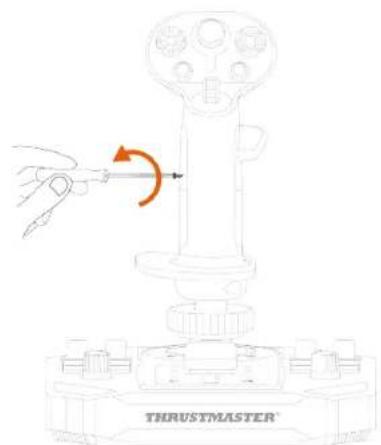
- Remove the two parts of the left thumb rest.
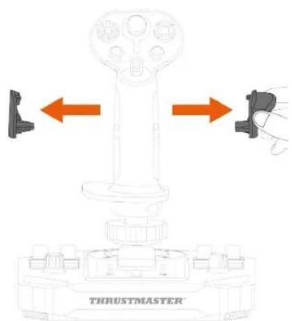
- Place the two parts of the right palm rest on the flight handle.
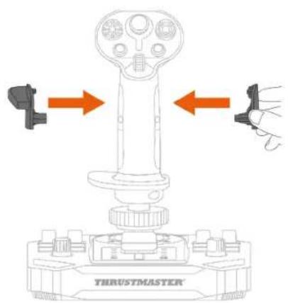
- Tighten the right thumb rest.
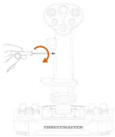
- Remove the detachable button located on the back of the flight handle.
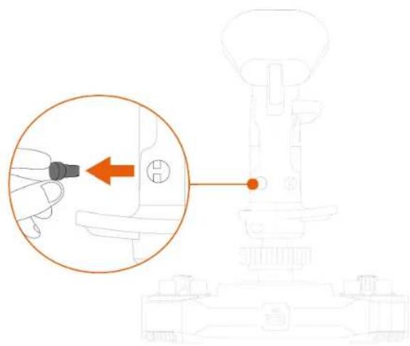
- Insert the detachable button below the thumb rest.
- Loosen the two screws that secure the wrist rest.
- Tighten the two screws used to secure the wrist rest.
Height adapter
https://support.thrustmaster.com/product/ava/
*Sold separately
7. T.A.R.G.E.T Advanced Programming Software

https://support.thrustmaster.com/product/sol-r-5-base
https://support.thrustmaster.com/product/ava
https://support.thrustmaster.com/product/hotas-magnetic-base
https://support.thrustmaster.com/product/sol-r-5-base
https://support.thrustmaster.com/product/ava
https://support.thrustmaster.com/product/hotas-magnetic-base
2. Technical features
4. Assembly
*Sold separately
PoV disabled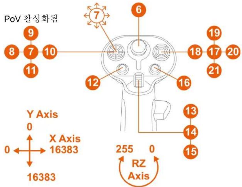
*Sold separately
HOTAS Magnetic Base* with Warthog Converter*
Base*
PoV disabled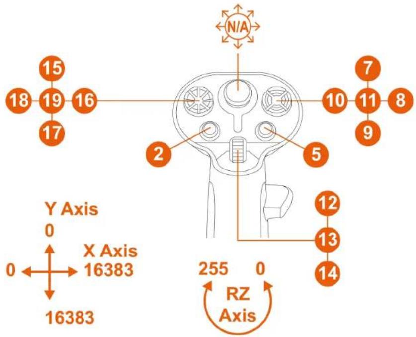
*Sold separately

To lock the rudder function:
To unlock the rudder function:
Multi-directional view hat switch
*Sold separately
Changing from right-handed mode to left-handed mode
Change
- Secure the left throttle with screws.
Height adapter
https://support.thrustmaster.com/product/ava/
https://support.thrustmaster.com/product/sol-r-3- ava-add-on-grip
https://support.thrustmaster.com/product/sol-r-5-base
https://support.thrustmaster.com/product/ava
https://support.thrustmaster.com/product/hotas-magnetic-base
TABLE OF CONTENTS
- PACKAGE CONTENTS......6
- TECHNICAL PARTS ....7
- INFORMATION REGARDING USE
OF THE FLIGHT STICK HANDLE 9
- ASSEMBLY 11
MAPPING 13
RUDDER FUNCTION....19
POV HAT SWITCH....21
- CONFIGURATION
FLIGHT STICK HANDLE....24
2. Technical parts
4. Assembly
POV hat button

Height adapter
With the adapter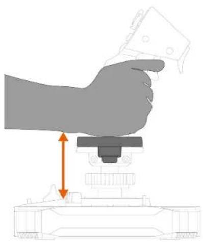
Right-handed mode
6. Compatibility

https://support.thrustmaster.com/product/ava/
https://support.thrustmaster.com/product/hotas-magnetic-base
PC (Windows® 10/11)
User manual

4. Assembly
Right-handed mode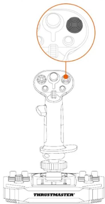
View function
can
be
disabled.
- Place the detachable button under the thumb rest.
- Place the detachable button under the thumb rest.
Height adapter
With the adapter
Right-handed mode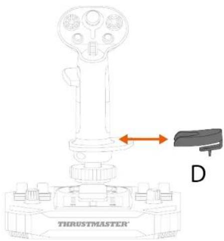
6. Compatibility

https://support.thrustmaster.com/product/ava/
7. Advanced
T.A.R.G.E.T-
PC (Windows® 10/11)
User manual

4. Assembly
Right-handed mode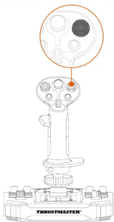
- Remove both parts of the right-hand thumb rest.
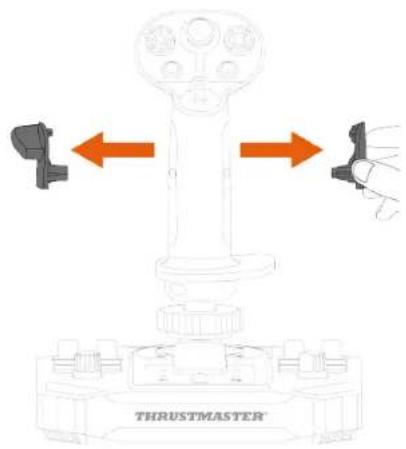
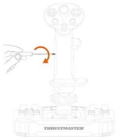
- Screw on the left thumb rest.
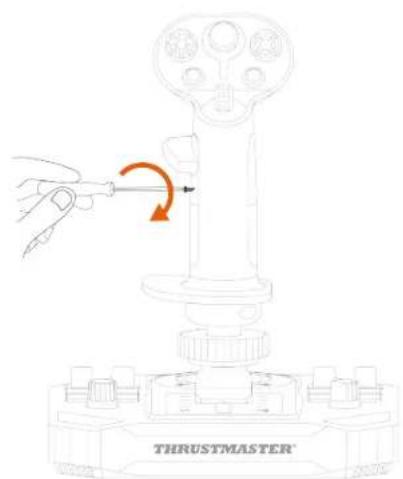
- Screw on the right thumb rest.
Height adapter
https://support.thrustmaster.com/product/ava/
PC (Windows® 10/11)
User manual

- https://support.thrustmaster.com/product/sol-r-5-base
- https://support.thrustmaster.com/product/ava
- https://support.thrustmaster.com/product/hotas-magnetic-base
4. Assembly
Right-handed mode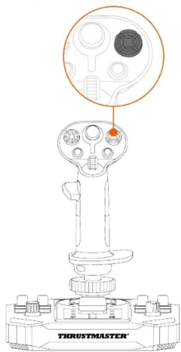
Height adapter
https://support.thrustmaster.com/product/ava/
- https://support.thrustmaster.com/product/hotas-magnetic-base
21..... "Point of View" POV
- 5.
24.
- *Sol-R o'or ob nisn't
HOTAS o'oz ix *AVA o'oz oby nizn't
28...... *Magnetic Base
29.
- 37...... 38...... 6. 39...... Μ'Ο'ΟΣ
- 41......הכלההוּרָהִיְהַעֹתָהִיְהַעֹתָהִיְהַעֹתָהִיְהַעֹתָהִיְהַעֹתָהִיְהַעֹתָהִיְה-T.A.R.G.E.T 7. 41...... 42...... 43...... 8.
SOL-R3
A V A
ADD-ON GRIP
תָאַעְרִי אַרְבָהָם Sol-R 3 AVA Add-On Grip
https://support.thrustmaster.com/product/sol-r-
5-base
AVA
https://support.thrustmaster.com/product/ava
https://support.thrustmaster.com/product/hotas-
magnetic-base

2
5
5
1
*

4. ;
*
*

"Point of View" POV
.2
.3 7.
.תְפַעָה בְּרָה

.4
.5
.71.הכלההוּרָהוּרָהוּרָהוּרָהוּרָהוּרָהוּרָהוּרָהוּרָהוּרָהוּרָהוּרָהוּרָהוּרָהוּרָה

.7 T'
.תְרָה

.2

.4
.5 vin ]
.תְרַעָה
.71.הכלההוּרָהוּרָהוּרָהוּרָהוּרָהוּרָהוּרָהוּרָהוּרָהוּרָהוּרָהוּרָהוּרָהוּרָהוּרָה:6

.7 TIN

https://support.thrustmaster.com/product/ava/

https://support.thrustmaster.com/product/sol-r-3-ava-add-on-grip
MFD Cougar, TFRP, TWCS, T.16000M FCS
https://support.thrustmaster.com/product/sol-r-3-ava-add-on-grip
1
https://support.thrustmaster.com/product/sol-r-5-
base
https://support.thrustmaster.com/product/ava
Thrustmaster HOTAS S Magnetic Base –
Thrustmaster
https://support.thrustmaster.com/product/hotas-
magnetic-base


- USER MANUAL
- TABLE OF CONTENTS
- SOL-R
- UPDATING THE FIRMWARE
- BOX CONTENTS
- TECHNICAL FEATURES
- INFORMATION REGARDING USE OF THE FLIGHT STICK GRIP
- DOCUMENTATION
- PINCH HAZARD
- ASSEMBLY
- MAPPING
- LEFT-HANDED MODE WITH SOL-R* BASE
- RIGHT-HANDED MODE WITH AVA* BASE
- LEFT-HANDED MODE WITH AVA* BASE
- WITH THE HOTAS MAGNETIC BASE* BASE EQUIPPED WITH WARTHOG CONVERTER
- RUDDER FUNCTION
- MULTIDIRECTIONAL POINT OF VIEW HAT SWITCH
- CONFIGURING THE FLIGHT STICK GRIP
- RIGHT-HANDED OR LEFT-HANDED MODE
- EXAMPLE OF CONFIGURATION WITH A SOL-R* BASE
- EXAMPLE OF CONFIGURATION WITH AN AVA* BASE OR A HOTAS MAGNETIC BASE* BASE
- CHANGING FROM RIGHT-HANDED MODE TO LEFT-HANDED MODE
- CHANGING FROM LEFT-HANDED MODE TO RIGHT-HANDED MODE
- HEIGHT ADAPTER
- COMPATIBILITY
- BASES
- CAMS
- T.A.R.G.E.T
- ADVANCED
- PROGRAMMING SOFTWARE
- INSTALLATION
- MAIN FEATURES
- FAQ AND TECHNICAL SUPPORT
- MY JOYSTICK ISN'T WORKING PROPERLY, OR SEEMS TO BE IMPROPERLY CALIBRATED
- I CAN'T CONFIGURE MY JOYSTICK
- MY JOYSTICK IS TOO SENSITIVE, OR NOT SENSITIVE ENOUGH
- MY JOYSTICK ISN'T WORKING
- THRUSTMASTER®
- MULTIDIRECTIONAL POINT-OF-VIEW
- SWITCH
- TECHNICAL SPECIFICATIONS
- MULTIDIRECTIONAL
- POINT-OF-VIEW HAT
- MULTIDIRECTIONAL POINT-OF-VIEW HAT SWITCH
- MOUNTING
- MULTI-DIRECTIONAL VIEW HAT SWITCH
- INTERCHANGEABILITY
- TO SWITCH FROM RIGHT-HANDED MODE TO LEFT-HANDED MODE
- SWITCH FROM LEFT-HANDED MODE TO RIGHT-HANDED MODE
- CHANGE FROM RIGHT-HANDED MODE TO LEFT-HANDED MODE
- CHANGE FROM LEFT-HANDED MODE TO RIGHT-HANDED MODE
- T.A.R.G.E.T ADVANCED PROGRAMMING SOFTWARE
- HOTAS MAGNETIC BASE* WITH WARTHOG CONVERTER
- TECHNICAL PARTS
- POV HAT BUTTON
- POINT OF VIEW" POV
Brand : THRUSTMASTER
Model : Sol-R 3 AVA Grip Add-On
Category : Game controller