ROWELD P500B Premium CNC SA - Industrial machine ROTHENBERGER - Free user manual and instructions
Find the device manual for free ROWELD P500B Premium CNC SA ROTHENBERGER in PDF.

| Product type | Butt fusion welding machine for plastic pipes |
| Brand | Rothenberger |
| Model | ROWELD P500B Premium CNC SA |
| Welding range of pipes | 200 - 500 mm diameter |
| Max cylinder stroke | 200 mm |
| Total cylinder area | 14.13 cm² |
| Base machine dimensions (L x W x H) | 1300 x 900 x 800 mm |
| Base machine weight (max.) | 238.5 kg (with insert sets) |
| Electrical supply milling machine | 400 V three-phase, 50/60 Hz, 1.75 A |
| Milling machine power | 1210 W absorbed / 750 W useful |
| Milling machine motor rotation speed | 140 min⁻¹ |
| Heating element supply | 400 V three-phase, 4000 W |
| Heating element diameter | 540 mm |
| Hydraulic unit supply | 400 V three-phase, 50/60 Hz, 2.75 A |
| Hydraulic unit power | 1905 W absorbed / 1100 W useful |
| Max hydraulic pressure | 135 bar |
| Oil tank capacity | 3.8 L |
| Recommended hydraulic oil | HLP 46 (ref. 53649) |
| Total weight complete installation | Approximately 350 kg (estimation) |
| Transport case dimensions | 2240 x 1300 x 1500 mm |
| Main functions | Butt welding with CNC control, parameter recording, USB transfer of protocols, Premium mode |
| Maintenance | Clean guide rods, replace oil every 12 months, check tightness |
| Safety | Emergency stop, thermal protection, safety switches on milling machine |
| Spare parts | Available via Rothenberger customer service (insert sets, milling blades, etc.) |
Frequently Asked Questions - ROWELD P500B Premium CNC SA ROTHENBERGER
User questions about ROWELD P500B Premium CNC SA ROTHENBERGER
0 question about this device. Answer the ones you know or ask your own.
Ask a new question about this device
Download the instructions for your Industrial machine in PDF format for free! Find your manual ROWELD P500B Premium CNC SA - ROTHENBERGER and take your electronic device back in hand. On this page are published all the documents necessary for the use of your device. ROWELD P500B Premium CNC SA by ROTHENBERGER.
USER MANUAL ROWELD P500B Premium CNC SA ROTHENBERGER
natural_image
Two industrial mechanical devices with control panels and a central device, no visible text or symbols.EN Instructions for use
rothenberger.com
Grundmaschine / Basic machine
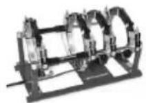
P250B P355B
1200000626 (SA) 1200000650 (SA)
1200000629 (VA) 1200001052 (VA)
natural_image
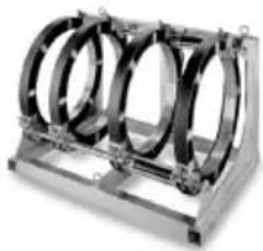
Mechanical component with three circular rings mounted on a metal frame (no visible text or symbols)P500B P630B
1200000651 1200000652
natural_image
Exterior view of a black electronic device with open lid and control panel (no visible text or symbols)P250B, P355B
53769 (230V-50Hz)
1200000952 (230V-60Hz)
P500B, P630B
54796 (400V-50/60Hz)
ROWELD P 250 B
ROWELD P 355 B
ROWELD P 500-630 B
20 14 16 182122
1234
EU-DECLARATION OF CONFORMITY
We declare on our sole accountability that this product conforms to the standards and guidelines stated.
DECLARATION EU DE CONFORMITÉ
Manufacturer/ authorized representative signature

ppa. Thorsten Bühl i. V. Maximilian Gottschalk
Director Corporate Technology Head of Innovation Management
Kelkheim, 20.01.2022
Technische Unterlagen bei/ Technical file at:
D-65779 Kelkheim/Germany
Intro
| DEUTSCH - Originalbetriebsanleitung!Bedienungsanleitung bitte lesen und aufbewahren! Nicht wegwerfen! Bei Schäden durch Bedienungsfehler erlischt die Garantie! Technische Änderungen vorbehalten! | Seite 2 |
| ENGLISHPlease read and retain these directions for use. Do not throw them away! The warranty does not cover damage caused by incorrect use of the equipment! Subject to technical modifications! | Page 26 |
| FRANÇAISLire attentivement le mode d'emploi et le ranger à un endroit sûr! Ne pas le jeter! La garantie est annulée lors de dommages dûs à une manipulation erronée! Sous réserve de modifications techniques! | Page 50 |
| ESPAÑOL¡Por favor, lea y conserve el manual de instrucciones! ¡No lo tire! ¡En caso de daños por errores de manejo, la garantía queda sin validez! Modificaciones técnicas reservadas! | Página 75 |
| NEDERLANDSLees de handleiding zorgvuldig door en bewaar haar goed! Niet weggooien! Bij schade door bedieningsfouten komt de garantieverlening te vervallen! Technische wijzigingen voorbehouden! | Bladzijde 100 |
| PORTUGUESQueiram ler e guardar o manual de instruções! Não deitar fora! Em caso de avarias por utilização incorrecta, extingue-se a garantia! Reservado o direito de alterações técnicas! | Pagina 124 |
| DANSKLæs betjeningsvejledningen, og gem den til senere brug! Smid den ikke ud! Skader, som måtte opstå som følge af betjeningsfejl, medfører, at garantien mister sin gyldighed! Ret til tekniske ændringer forbeholdes! | Side 149 |
| SVENSKALäs igenom bruksanvisningen och förvara den väl! Kasta inte bort den! Garantin upphör om apparaten har använts eller betjänats på ett felaktigt sätt! Med reservation för tekniska ändringar! | Sida 172 |
| NORSKLes bruksanvisningen og oppbevar den vell! Ikke kast den! Oppstår skader på grunn av betjeningsfeil opphører garantiens gyldighet! Tekniske forandringer forbeholdes! | Side 195 |
| SUOMILue ja säilytä tämä käyttöohje! Älä heitä pois! Takuu ei kata käyttövirheistä aiheutuvia vahinkoja! Oikeudet teknisiin muutoksiin pidätetään! | Sivulta 218 |
| POLSKIInstrukcję obsługi proszę przeczytać i zachować! Nie wyrzucać! Przy uszkodzeniach wynikajacych z blędów obsługi wygasa gwarancja! Zmiany techniczne zastrzeżone! | Strony 241 |
| TÜRKÇEKullanim açıklamalarini lütfen dikkatlice okuyunuz ve bir yerde muhafaza ediniz! Çöpe atmayiniz! Kullaniminda yapılan hatalar, garantinin silinmesine neden olur! Teknik deðipiklikler yapma hakkimiz saklidir! | Sayfa 266 |
| MAGYARKérjük, olvassa el és örizze meg a kezelési utasítást! Ne dobja el! A helytelen kezelésből származó károsodások esetén megszůnik a jótállás! Můszaki változtatások fenntartva! | Oldaltól 289 |
| SLOVENSKOPreberite navodila za uporabo in jih shranite! Ne odvrzite jih! Ob poškodbah zaradi napak v uporabi preneha veljati garancija! Pridržujemo si pravico do tehničnih sprememb! | Stran 313 |
| SLOVENSKÝPrečítajte si prosím návod na obsluhu a uschovajte ho! Návod nezahadzujte! Pri poškodeniach v dôsledku chýb pri obsluhe zaniká záruka! Technické zmeny vyhradené! | Strana 336 |
| БЪЛГАРСКИПрочетете внимателно и запазете инструкцията за експлоатация! Не я захвърляйте или унищожавайте! При настъпили дефекти вследствие на неправилно обслужване гаранцията отпада! Технически изменения по уреда са изключително в компетенцията на фирмата производител! | Страница 360 |
| РУССКИЙПрочите инструкцию по эксплуатации и сохраняйте её для дальнейшего использования! В случае поломки инструмента из-за несоблюдения инструкции клиент теряет право на обслуживание по гарантии! Возможны технические изменения! | Страница 385 |
Inhalt Seite
∅ ≤ 355mm = 0,5mm, ∅ 400... < 630mm = 1,0mm, ∅ 630... < 800mm = 1,3mm.


service@rothenberger.com - www.rothenberger.com
7 Entsorgung
1.1 Intended use 27
1.2 General Power Tool Safety Warnings 27
2 Technical Data 29
3 Function of the Unit 30
3.1 Description.... 30
3.1.1 Basic unit (A) 30
3.1.2 Hydraulic unit (B) 30
3.2 Operating instructions.... 31
3.2.1 Commissioning 31
3.2.2 Measures for preparing welding 34
3.2.3 Welding 36
3.2.4 Welding in premium mode 39
3.2.5 Shut-down....43
3.3 General requirements 43
3.4 Important information on welding parameters 43
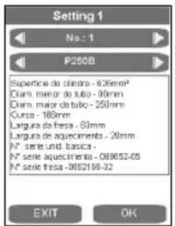
3.5 Setting parameters 43
3.6 Set date and time....45
3.7 Setting up or selecting machine configurations 46
3.8 Error messages 47
4 Care and Maintenance.... 48
5 Accessories 48
6 Customer service 48
7 Disposal 49
Markings in this document:

Danger!
This sign warns against the danger of personal injuries.

Caution!
This sign warns against the danger of property damage and damage to the environment.

Call for action
1.1 Intended use
ROWELD P250-630B Premium CNC models are only to be used for producing welded joints on PE - PP and PVDF tubes according to the technical data. The user bears sole responsibility for any damage caused by improper use.
1.2 General Power Tool Safety Warnings

WARNING! Read all safety warnings, instructions, illustrations and specifications provided with this power tool.
Failure to follow all instructions listed below may result in electric shock, fire and/or serious injury.
Save all warnings and instructions for future reference.
The term “power tool” in the warnings refers to your electrically-operated (corded) power tool or battery-operated (cordless) power tool.
1) Work area safety
a) Keep work area clean and well lit. Cluttered and dark areas invite accidents.
b) Do not operate power tools in explosive atmospheres, such as in the presence of flammable liquids, gases or dust. Power tools create sparks which may ignite the dust or fumes.
c) Keep children and bystanders away while operating a power tool. Distractions can cause you to lose control.
2) Electrical safety
a) Power tool plugs must match the outlet. Never modify the plug in any way. Do not use any adapter plugs with earthed (grounded) power tools. Unmodified plugs and matching outlets will reduce risk of electric shock.
b) Avoid body contact with earthed or grounded surfaces, such as pipes, radiators, ranges and refrigerators. There is an increased risk of electric shock if your body is earthed or grounded.
c) Do not expose power tools to rain or wet conditions. Water entering a power tool will increase the risk of electric shock.
d) Do not abuse the cord. Never use the cord for carrying, pulling or unplugging the power tool. Keep cord away from heat, oil, sharp edges and moving parts. Damaged or entangled cords increase the risk of electric shock.
e) When operating a power tool outdoors only, use an extension cords suitable for outdoor use. Use of a cord suitable for outdoor use reduces the risk of electric shock.
f) If operating a power tool in a damp location is unavoidable, use a residual current device (RCD) protected supply. Use of an RCD reduces the risk of electric shock.
3) Personal safety
a) Stay alert, watch what you are doing and use common sense when operating a power tool. Do not use a power tool while you are tired or under the influence of drugs, alcohol or medication. A momentary lack of attention while operating power tools may result in serious personal injury.
b) Use personal protective equipment. Always wear eye protection. Protective equipment such as dust mask, non-skid safety shoes, hard hat, or hearing protection used for appropriate conditions will reduce personal injuries.
c) Prevent unintentional starting. Ensure the switch is in the off-position before connecting to power source and/or battery pack, picking up or carrying the tool. Carrying power tools with your finger on the switch or energising power tools that have the switch on invites accidents.
d) Remove any adjusting key or wrench before turning the power tool on. A wrench or a key left attached to a rotating part of the power tool may result in personal injury.
e) Do not overreach. Keep proper footing and balance at all times. This enables better control of the power tool in unexpected situations.
f) Dress properly. Do not wear loose clothing or jewellery. Keep your hair, clothing and gloves away from moving parts. Loose clothes, jewellery or long hair can be caught in moving parts.
g) If devices are provided for the connection of dust extraction and collection facilities, ensure these are connected and properly used. Use of dust collection can reduce dust-related hazards.
h) Do not let familiarity gained from frequent use of tools allow you to become complacent and ignore tool safety principles. A careless action can cause severe injury within a fraction of a second.
4) Power tool use and care
a) Do not force the power tool. Use the correct power tool for your application. The correct power tool will do the job better and safer at the rate for which it was designed.
b) Do not use the power tool if the switch does not turn it on and off. Any power tool that cannot be controlled with the switch is dangerous and must be repaired.
c) Disconnect the plug from the power source and/or remove the battery pack, if detachable, from the power tool before making any adjustments, changing accessories, or storing power tools. Such preventive safety measures reduce the risk of starting the power tool accidentally.
d) Store idle power tools out of the reach of children and do not allow persons unfamiliar with the power tool or these instructions to operate the power tool. Power tools are dangerous in the hands of untrained users.
e) Maintain power tools and accessories. Check for misalignment or binding of moving parts, breakage of parts and any other condition that may affect the power tool's operation. If damaged, have the power tool repaired before use. Many accidents are caused by poorly maintained power tools.
f) Keep cutting tools sharp and clean. Properly maintained cutting tools with sharp cutting edges are less likely to bind and are easier to control.
g) Use the power tool, accessories and tool bits etc., in accordance with these instructions, taking into account the working conditions and the work to be performed. Use of the power tool for operations different from those intended could result in a hazardous situation.
h) Keep handles and grasping surfaces dry, clean and free from oil and grease. Slippery handles and grasping surfaces do not allow for safe handling and control of the tool in unexpected situations.
5) Service
a) Have your power tool serviced by a qualified repair person using only identical replacement parts. This will ensure that the safety of the power tool is maintained.
2 Technical Data
| P250B | P355B | P500B | P630B | ||
| Basic unit CNC SA/VA: | |||||
| Pipe welding range ∅ (mm) | 90-250 | 90-355 | 200-500 315-630 | ||
| Pipe capacity | SDR series see welding tables + observe pressure max. hydraulic unit | ||||
| Cylinder stroke, max. (mm) | 150 | 150 | 200 200 | ||
| Total cylinder surface (cm2) | 6,26 | 6,26 | 14,13 14,13 | ||
| Leading dimensions: | |||||
| Length (mm) | 810 | 795 | 1300 1300 | ||
| Width (mm) | 485 | 600 | 900 1060 | ||
| Height (mm) | 415 | 535 | 800 920 | ||
| max. Weight * (SA kg) | 59,0 | 80,2 | 238,5 323,4 | ||
| max. Weight * (VA kg) | 61,3 | 83,8 | |||
| * incl. reduction clamp inserts for the smallest pipe diameter | |||||
Trimmer unit:
| Power supply | 230 V | 230 V | 400 V, 3~ | 400 V, 3~ |
| 50/60 Hz | 50/60 Hz | 50/60 Hz | 50/60 Hz | |
| 3,5 A | 4,8 A | 1,75 A | 2,55 A | |
| Rated power input/output (W) | 750/470 | 1050/650 | 1210/750 | 1770/110 |
| Rotary speed (min-1) | 660 | 726 | 140 | 140 |
| Idle running speed milling disc (min-1) | 85 | 66 | 31 | 24 |
| Noise pressure level dB(A) LpA | KpA | 82 | 3 | 83 | 3 | 48 | 3 | 52 | 3 |
| Sound power level dB(A) LWA | KWA | 93 | 3 | 94 | 3 | 59 | 3 | 63 | 3 |
| Weight (kg) | 15 | 22,4 | 68 | 123 |
Heating plate CNC SA/VA:
| Power supply | 230 V | 230 V | 400 V | 400 V |
| 50/60 Hz | 50/60 Hz | 50/60 Hz | 50/60 Hz | |
| 1500 W | 2500 W | 4000 W | 8000 W | |
| Heating plate - diameter (mm) | 300 | 380 | 540 | 660 |
| Weight (SA/VA kg) | 5,5/13 | 9,1 | 32 | 49 |
Carrying frame CNC SA/VA:
| Weight (SA/VA kg) | 8,2/7,6 | 9,6 | 55 | 70 |
| P250B, P355B | P500B, P630B |
Hydraulic unit:
| Power supply | 230 V - 50 Hz - 4,17 A | 400 V - 50/60 Hz - 2,75 A |
| 230 V - 60 Hz - 4,17 A |
| Rated power input/output (W) | 880/550 | 1905/1100 |
| Pump capacity (l/min) | 2,2/ 2,6 | 4,5/ 5,4 |
| Oil tank capacity (l) | 1,1 | 3,8 |
| Pressure max. (bar) | 135 | 135 |
| Hydraulic-oil | HLP-46 (no.: 53649) |
| Dimensions (LxWxH, mm) | 540 x 310 x 433 | 540 x 310 x 433 |
| Noise pressure level dB(A) LpA | KpA......62 | 3 ...... 68 | 3 |
| Sound power level dB(A) LWA | KWA ....73 | 3 ....79 | 3 |
| Weight (kg) | 33,7 | 38,2 |
P250B P355B P500B P630B
Overall length:
| Total connected load (kW) | 3,2 | 4,3 | 7,2 | 11,7 |
Transport case dimensions:
Length (mm) 1200 1200 2240 2240
Width (mm) 800 800 1300 1300
Height (mm)....900....900....1500....1500
The noise level during operation can exceed 85 dB (A). Wear hearing protection!
3 Function of the Unit
3.1 Description
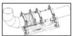
ROWELD P250-630B Premium CNC are compact, transportable heating element butt welding machines with a CNC module for exact control, maintenance and storing according to DVS guidelines. They also allow log files to be transferred through a USB connection specially designed for use on construction sites, and particularly in pipe trenches. Of course, the tools are very well suited for use in the workshop.
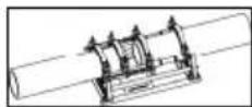
Welding of pipe-pipe connections, T-joints, pipe bends and welding neck can be made.
The essential machine components are:
Basic unit, reduction clamp insets, hydraulic unit with CNC module, trimmer unit, heating plate, carrying frame.
ROWELD P250B Premium CNC: When welding pipe bends with a narrow radius of the maximum diameter of the machine, this bevelled upper clamping tool should be used as an accessory.
ROWELD P500-630B Premium CNC: To insert and remove the trimmer and the heating plate we recommend using the electrical hoist (optional accessory, must be ordered separately).
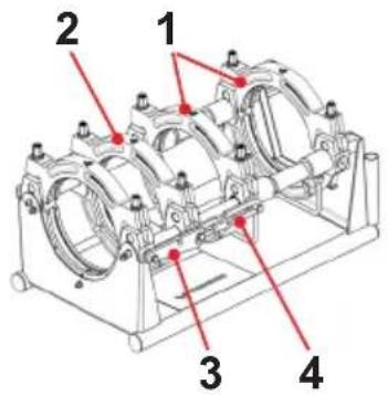
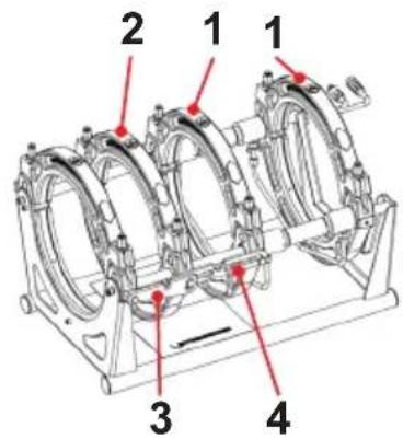
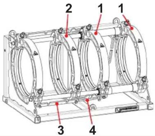
3.1.1 Basic unit (A)
1 Movable clamps 3 Spacer with locking notch
2 Sliding clamps 4 Heating element take-off device
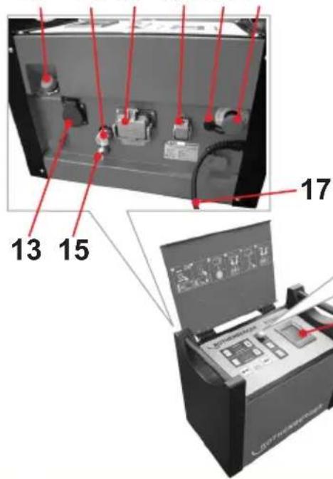
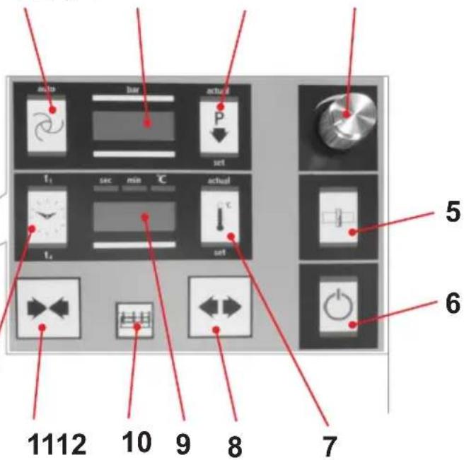
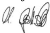
3.1.2 Hydraulic unit (B)
| 1 | Automatic button | 12 | Timer button |
| 2 | Pressure button | 13 | Socket for cutting unit |
| 3 | Pressure release button | 14 | Quick coupling for pipe collar |
| 4 | Adjusting knob | 15 | Quick coupling for plug |
| 5 | Cutting button | 16 | Heating element connector |
| 6 | ON/OFF button | 17 | Electrical plug |
| 7 | Heating button | 18 | Emergency OFF |
| 8 | "Open" machine | 19 | Touch screen PC |
| 9 | Temperature and time display | 20 | Oil filling port with dipstick |
| 10 | Release button | 21 | USB connection |
| 11 | "Close" machine | 22 | Basic machine plug and socket device |
The hydraulic unit allows the operator to operate the welding machine and perform the functions indicated by the following symbols:
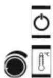
Turning the hydraulic assembly on and off
Press the „Heating“ button to turn the heating element on. Set the desired heating element temperature by pressing the „Heating“ button and turning the adjustment knob. The value will be shown in the temperature display, and then the current value is again shown

Use the adjustment knob to set the pressure for cutting, aligning, heating and joining. The value is shown in the „Pressure“ display. Three seconds after the settings are made, the current value is shown. Pressing the rotary knob displays and allows changes to be made to the service parameters
To bring the clamping elements together, press the release button and „close“ the machine
Pressure release button
To separate the clamping elements, press the release button and „open“ the machine
Press the release button and the cutting button to turn on the cutting unit socket. Pressure is automatically set to 10 bar and can be increased to a maximum of 20 bar using the adjusting knob. (In special situations, such as on slopes, the pressure can be set to a maximum of 50 bar by changing P004)
Activate the timer by pressing it once. By pressing the button and turning the adjusting knob, the t1 time can be set in seconds. Pressing the button longer switches over to t4. By pressing the button and turning the adjusting knob, the t4 time can be set in minutes. The timer is started manually by shortly pressing on the timer key if the timer indicator lights up with t1 or t2
Pressing the Automatic button allows the set pressure to be monitored and regulated, if necessary, during warming up (timer t1 active) and the joining process (timer t4 active)
Release button for actuating the service parameter
3.2 Operating instructions
The welding machines are suitable for operation at ambient temperatures between -10^ and +40^ .
They are suitable for a stationary power supply of 230 V 50/60 Hz and 400 V 50/60 Hz. If a power generator is used, the welder must clarify the required power with the manufacturer of the generator.

In accordance with national or EU ordinances and guidelines, e. g. DVS 2212, Section I, only duly qualified and authorised personnel are allowed to operate the ROWELD welding machines!
3.2.1 Commissioning

Please read through the operating instructions and safety instructions attentively before you put the butt fusion welding machine into operation!
Do not use the heating element in explosive environments or bring it into contact with easily flammable materials!
Stay a safe distance away from the machine. Do not stand or reach into the machine. Keep other people away from the work area!
Before every start-up, check the oil level of the hydraulic unit. The oil level must be between the min. and max. marking on dipstick in the oil filler cap. If necessary, add HLP 46 hydraulic oil!
Transport and set the hydraulic unit only in a horizontal position. If it is set at an angle, oil escapes from the vented plugs with the dipstick!
If there is a hazard, press the emergency OFF switch (18). Before each start-up, make sure that the emergency OFF is not locked!
→ Connect the two hydraulic hoses to the basic machine using the quick coupling (14,15) on the hydraulic unit.

Protect the quick couplings from contamination. Replace leaky couplings immediately!
→ Connect milling unit mains plug to socket (13), heating element plug to plug and socket device (16), and basic machine plug to plug and socket device (22).
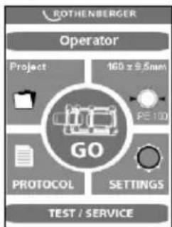
Connect the electrical plug of the hydraulic unit (17) to the power supply according to the model plate. If the start screen does not appear, unlock the emergency OFF switch. A signal tone will sound, and a dot will light up on the display (2).
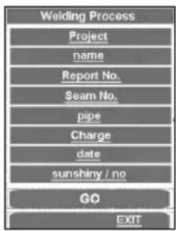
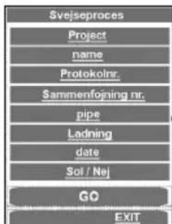
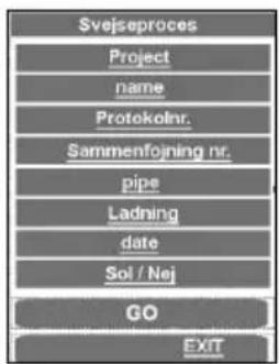
Upon first use, check the date and time. To do this, press the GO button. (To change, see point 3.6). To close the menu, press EXIT.
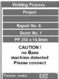
If you press GO key and no basic machine is connected, the following message appears: "Attention! No basic machine is detected. Please connect."
If the error message still appears after connection, then the connection is defect, but there is the possibility to weld and log in premium mode (see 3.2.4).
→ During first use, set the language. German is set by default. To change the settings, press and change using OK in Setting 2.
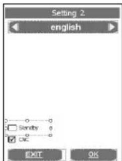
Use the arrow keys to select the desired language and press OK to confirm. The selected language will be saved after the first welding process.
It is possible to switch the screen to standby mode. The screen saver becomes active when the hydraulic unit is shut off with the button (6).
→ Turn the hydraulic unit on (press button (6)).
After it is switched on, the heating element warms up.
The current temperature is shown on the display (9). The control is active when a dot lights up on the display. When the set temperature is reached, the two LEDs (current and target) light up. After another 10 minutes, the heating element is ready to use. Check the temperature with a temperature measurement device.
To adjust the temperature of the heating element, see point 3.5.

Risk of serious injury! The heating plate can reach temperatures of over 300°C (575°F)! We highly recommend storing the heating plate in the designated carrying frame immediately after use!
Pressing longer on the button (7) shuts off the heat. The dot on the display (9) goes off. Pressing again turns the heat back on.

Hydraulik ROWELD P500-630B: Check the direction of rotation! The machines are clamped to turn clockwise at the factory. Open and close the machine with the hydraulic unit. If there is no movement, use an appropriate tool to switch the phase inverter on the electrical plug!

Note: Do not turn the hydraulic unit on if the direction of rotation is wrong (this may destroy it)!
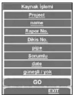
→ Enter or select the welder name „Operator“.
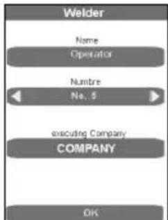

In the entry form, saved welders can be selected, new welder names can be entered, and existing welder names can be deleted with DEL and reentered. All entry forms are confirmed and saved with the ENTER or OK button, and the next program step is called up. The EXIT button closes the entry form without saving it.
→ Enter or select a project.
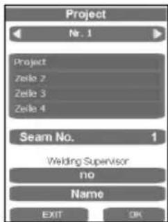

The entry forms can be used to select saved projects or enter new project names. Close and save using the ENTER key.
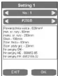
→ Select a pipe.
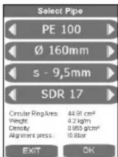
→ Use the arrow keys to select the desired pipe and press OK to confirm.
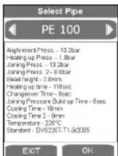
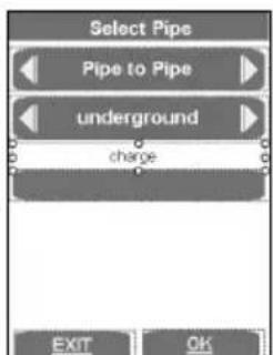
In this final overview of the pipe parameters, the pipe data are shown according to DVS guidelines. Press OK to show the window for the welding parts and laying system.
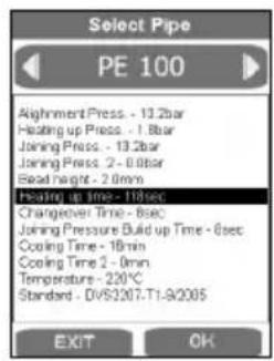

Non-standard modifications can be made by pressing the relevant display field and pressing ENTER to save. In the Standard point, the description then changes. This can be entered into the comments field later before printing out the log on the computer. After the pipe data have been confirmed and saved by pressing OK, the main menu appears.
For P500-630B: For lifting the milling equipment and the heating element, use lifting device 53410 (P500B) or 53323 (P630B), or a suitable tool.
3.2.2 Measures for preparing welding
→ Pipes smaller than the maximum welding range (diameter) of the machine, mount the adapter clamping inserts suited for the pipe diameter with the Allen screws found in the accessories kit.
ROWELD P250-355B: consisting of six wide-surface shells and two small-surface shells.
ROWELD P500-630B: consisting of six wide-surface shells and two small-surface shells (for diameters up to 450 mm) or 8 wide-surface shells (for diameters >500 mm).
In so doing, please observe that the small-surface shells are mounted to the two lower external main clamps. These are used in the left basic clamping element below and above only for pipe to pipe bend connections.
→ Insert the plastic pipe or fitting in the clamping device (use dolly with longer pipe < 2,5m sections) and tighten brass nut on the upper clamps. Adjust brass nuts (tighten or loosen) to compensate for any ovalness.
→ For pipe-to-pipe connections, the two spacers must be engaged in both left clamping elements (standard configuration at delivery).

Attention: Under no circumstances should the spacers be installed diagonally offset!
The pipes are each held by two clamping elements.
P250-355B: For pipe-to-fitting connections, the two spacers must be engaged in both middle clamping elements, and the heating element take-off device is suspended into the left clamping elements. When some fittings are being processed in certain positions, such as horizontal bends or welding necks, it is necessary to remove the heating element take-off device.
→ P500-630B: For pipe-to-fitting connections, the spacers must be swivelled to the other side and engaged in the middle clamping elements.

Attention: Under no circumstances should the spacers be installed diagonally offset!
The pipe is inserted into three clamping elements, and the fitting is held by one clamping element. Thus, the movable clamping element can be shifted on the rod as space requirements demand during clamping.
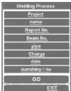
→ Start the welding process with GO.

In this final overview, the last changes can be made by clicking on the relevant subpoint and confirming with GO.
In CNC mode, control is executed by the touch PC. All functions outside the touch PC, except for the power key (6), are blocked.
The welding process can be cancelled by the power key. The key lock is then raised and the relevant message appears in the display.
Pressing the arrow key causes the machine to start up.
EXIT takes the program to the main menu without saving.
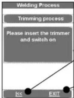
→ Place the electrical cutting unit between the two work pieces to be welded.
→ P250-355B: Switch on the miller motor and lock the switch in place.
P500-630B: Verify the direction of rotation! The machines were polarised to turn clockwise before leaving our factory!
→ Switch on the milling unit by pressing the text field. The cutting disks must run in the cutting direction. If they don't, use an appropriate tool to switch the phase inverter on the electrical plug.
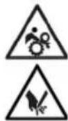
Risk of serious injury! During operation trimmer unit, stay a safe distance away from the machine, and do not reach into the rotating knife. Use trimmer in working position only and return it into the designated carrying frame immediately after use. Ensure that the safety switch functions properly at all times to avoid any accidental starting of the trimmer away from the basic machine!
→ Clamping elements move together automatically. The cutting pressure can be increased with the rotary knob (4). Standard cutting pressure is up to 20 bar, but it can be raised to 50 bar, see point 3.5.

An excessively high milling pressure can lead to overheating and damage to the miller drive. When the milling drive is overloaded or at rest, raise the machine and reduce the pressure (s. 3.5)!
→ After the shavings with a chip thickness of <= 0.2mm are discharged continuously from the milling cutter, press on text field. Milling unit is switched off and the clamping elements start up.
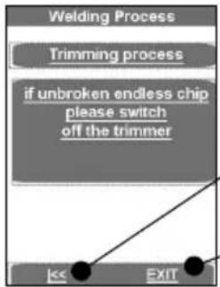
flowchart
graph TD
    A["Welding Process"] --> B["Trimming process"]
    B --> C{if unbroken endless chip please switch off the trimmer}
    C --> D["Exit"]
The arrow keys take the program back to „Please insert the trim-mer...”
EXIT takes the program to the main menu without saving
→ Wait until the cutting disks have stopped. Remove the cutting unit from the basic machine and put it in the storage case.
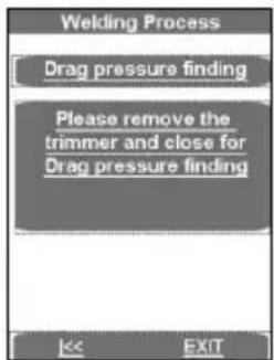
→ Press text field, the work pieces move together and the drag flow pressure is measured. The measured drag pressure will automatically be added to the equalization, warm-up and cutting pressure.

Stay a safe distance away from the machine. Do not stand or reach into the machine. Keep other people away from the work area!
The arrow keys take the program back to "Drag pressure finding"
The arrow keys take the program back to "Please insert the trimmer..."
EXIT takes the program to the main menu without saving
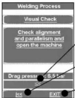
→ Check, whether the pipes are resting firmly in the clamping elements, whether the welding areas are plane, parallel and axially aligned.
Should the joint surfaces show any misalignment, repeat the trimming procedure. For best results the workpiece ends should not be mismatched by more than 10% of the wall thickness and the maximum gap between the joint surfaces no more than:
≤355mm=0,5mm,400...<630mm=1,0mm,630...<800mm=1,3mm.
This recommendation does not release you from your obligation to observe national welding guidelines. Clear away any remaining shavings with a clean brush.

CAUTION! Do not touch the trimmed, ready to weld surfaces. Ensure that the surfaces are free of any and all containments and foreign objects!
3.2.3 Welding

Risk of injury! Keep a safe distance from the machine when mechanically closing clamps and moving workpieces. Keep hands, limbs and objects such as clothing, tools etc. away from running machine!
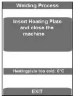
The form shows the temperature of the heating plate.
The display bar shows up in blue if the temperature is too low, and in red when it is too high. When it is in the target range, it displays as green.
The machine can only be run in the green target range.
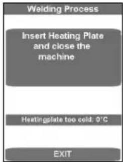
→ Heating plate SA: Insert the heating element between the two work pieces in the basic machine, and make sure that the heating plate supports are seated in the notches of the removal device.
→ Heating plate VA: Place the heating element on both acceptance points in the basic machine and swivel the hot plates between the pipes.
→ Move the machine together by pressing the text field. The adjusting pressure is automatically adjusted and maintained.
Now all welding parameters have been stored, and the log activated.
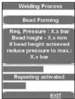
The upper progress bar shows whether the pressure lies within the correct range (green) or within a permissible (yellow) tolerance range or whether it lies outside (red) the tolerance range. The actual pressure is shown on the display (2).
As soon as the necessary bulge height has been uniformly reached on the entire circumference of both tubes, the pressure is automatically released and the warm-up process begins.
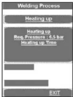
flowchart
graph TD
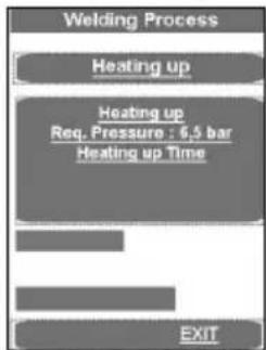
A["Welding Process"] --> B["Heating up"]
B --> C["Heating up\nReq. Pressure : 6.5 bar\nHeating up Time"]
C --> D["EXIT"]
→ Set the pressure so that the ends of the work pieces can again be lain uniformly and nearly pressure-free onto the heating element.
A signal sounds shortly before the end of the warm-up time.
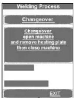
→ At the end of the warm-up period, the work pieces move apart, the heating element SA must be removed, or the heating element VA is automatically swung out and the work piece ends move together.
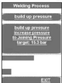
The pressure is linearly raised to the appropriate joining pressure.
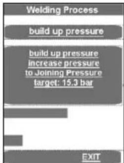
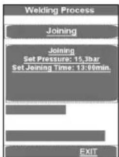
When joining pressure is reached, the program automatically goes to the joining process and the t4 timer starts.
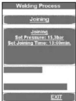
The upper progress bar shows whether the pressure lies within the correct range (green) or within a permissible (yellow) tolerance range or whether it lies outside (red) the tolerance range. The time lapse is shown below. The actual pressure is shown in display (2) and the remaining joining time in display (9).
The pressure is automatically monitored and regulated. If the hydraulic system repumps too often (meaning there is high pressure loss), have it checked.
→ Put the heating element back in the storage case.
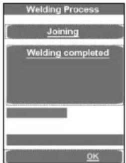
→ The welding process is ended after the cooling down time has expired, is stored, a signal sounds and the pressure is dissipated automatically.
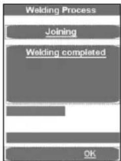
→ Conclude with use of the welding menu by pressing OK.
→ Dissipate the pressure completely by pressing the button (3).
→ Unclamp the welded work pieces and remove them.
→ Move the basic machine apart. The machine is ready for the next welding cycle.
Transferring the log:

In the Log menu item, these can be saved with OK, if a USB stick is connected. The window then closes automatically.
This report file should be processed using the ROTHENBERGER Dataline 2 software and a computer.
All welding parameters can be found in the enclosed welding tables.
3.2.4 Welding in premium mode
→ Press Premium mode.

→ Enter the ambient temperature and press the Enter button. The following appears if the temperature was not entered correctly:

flowchart
graph TD
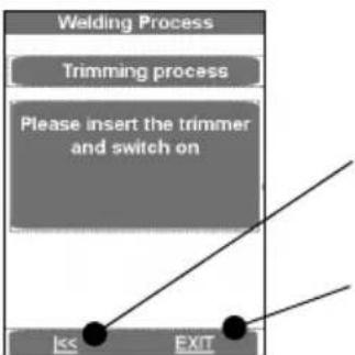
A["Welding Process"] --> B["Trimming process"]
B --> C["Please insert the trimmer and switch on"]
C --> D["Exit"]
D --> E["Exit"]
Pressing the arrow key causes the machine to start up.
EXIT takes the program to the main menu without saving.
→ Place the electrical cutting unit between the two work pieces to be welded.
→ P250-355B: Switch on the miller motor and lock the switch in place.
P500-630B: Verify the direction of rotation! The machines were polarised to turn clockwise before leaving our factory!
→ Switch on the milling unit by pressing the text field. The cutting disks must run in the cutting direction. If they don't, use an appropriate tool to switch the phase inverter on the electrical plug.
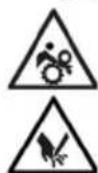
Risk of serious injury! During operation trimmer unit, stay a safe distance away from the machine, and do not reach into the rotating knife. Use trimmer in working position only and return it into the designated carrying frame immediately after use. Ensure that the safety switch functions properly at all times to avoid any accidental starting of the trimmer away from the basic machine!
→ Clamping elements move together automatically. The cutting pressure can be increased with the rotary knob (4). Standard cutting pressure is up to 20 bar, but it can be raised to 50 bar, see point 3.5.

An excessively high milling pressure can lead to overheating and damage to the miller drive. When the milling drive is overloaded or at rest, raise the machine and reduce the pressure (s. 3.5)!
→ After the shavings with a chip thickness of <= 0.2mm are discharged continuously from the milling cutter, press on text field. Milling unit is switched off and the clamping elements start up.

→ Wait until the cutting disks have stopped. Remove the cutting unit from the basic machine and put it in the storage case.

→ Press text field, the work pieces move together and the drag flow pressure is measured. The measured drag pressure will automatically be added to the equalization, warm-up and cutting pressure.

Stay a safe distance away from the machine. Do not stand or reach into the machine. Keep other people away from the work area!

→ Check, whether the pipes are resting firmly in the clamping elements, whether the welding areas are plane, parallel and axially aligned.
Should the joint surfaces show any misalignment, repeat the trimming procedure. For best results the workpiece ends should not be mismatched by more than 10% of the wall thickness and the maximum gap between the joint surfaces no more than:
≤355mm=0,5mm,400...<630mm=1,0mm,630...<800mm=1,3mm.
This recommendation does not release you from your obligation to observe national welding guidelines. Clear away any remaining shavings with a clean brush.

CAUTION! Do not touch the trimmed, ready to weld surfaces. Ensure that the surfaces are free of any and all containments and foreign objects!
Welding process in premium mode:

Risk of injury! Keep a safe distance from the machine when mechanically closing clamps and moving workpieces. Keep hands, limbs and objects such as clothing, tools etc. away from running machine!
The form shows the temperature of the heating plate.
The display bar shows up in blue if the temperature is too low, and in red when it is too high. When it is in the target range, it displays as green.
→ Insert the heating element between the two work pieces in the basic machine, and make sure that the heating plate supports are seated in the notches of the removal device.
→ Close the machine. The equalization pressure is automatically set. Hold the pressure.
Now all welding parameters have been stored, and the log activated.
If the welding process is interrupted using EXIT the message "Termination by the operator" appears, the pressure is dissipated and the welding parameters are stored. Confirm the message with OK, then the program jumps to the main menu.
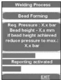
The upper progress bar shows whether the pressure lies within the correct range (green) or within a permissible (yellow) tolerance range or whether it lies outside (red) the tolerance range. The actual pressure is shown on the display (2).
→ Release the pressure using the Automatic button (1) as soon as the required bulge height has been reached evenly around the whole circumference of both pipes. The warming up time t1 begins to run.
→ Set the pressure so that the ends of the work pieces can again be lain uniformly and nearly pressure-free onto the heating element.
A signal sounds shortly before the end of the warm-up time.
→ After the warm-up time is over, separate the work pieces, remove the heating element and bring the work pieces back together.

→ Stop the bringing together process by releasing the buttons shortly before the ends of the workpieces make contact (about 1 cm.) and press the buttons again immediately. The pressure is linearly raised to the appropriate joining pressure.
When joining pressure is reached, the program automatically goes to the joining process and the t4 timer starts.
The upper progress bar shows whether the pressure lies within the correct range (green) or within a permissible (yellow) tolerance range or whether it lies outside (red) the tolerance range. The time lapse is shown below. The actual pressure is shown in display (2) and the remaining joining time in display (9).
Attention: Hold down the Release button (10) and the Close machine button (11) until the joining pressure is reached. Then the hydraulic unit shuts off and the buttons can be released!
→ The pressure is monitored and automatically regulated again. If the hydraulic system repumps too often (meaning there is high pressure loss), have it checked.
→ Put the heating element back in the storage case.
→ The welding process is ended after the cooling down time has expired, is stored, a signal sounds and the pressure is dissipated automatically.
→ Conclude with use of the welding menu by pressing OK.
→ Dissipate the pressure completely by pressing the button (3).
→ Unclamp the welded work pieces and remove them.
→ Move the basic machine apart. The machine is ready for the next welding cycle.
Transferring the log:

In the Log menu item, these can be saved with OK, if a USB stick is connected. The window then closes automatically.
This report file should be processed using the ROTHENBERGER Dataline 2 software and a computer.
All welding parameters can be found in the enclosed welding tables.
3.2.5 Shut-down
→ Use the button (6) to turn off the hydraulic unit.

Let the heating element cool or stow it in such a way that no adjacent materials can be ignited!
→ Remove trimmer unit, heating plate and hydraulic unit mains plugs from power outlet and roll up cables.

Transport and set the hydraulic unit only in a horizontal position. If it is set at an angle, oil escapes from the vented plugs with the dipstick!
→ Disconnect and roll up hydraulic hoses.

Important! Protect couplings from damage and dirt!
3.3 General requirements
As weather and ambient conditions can seriously effect welding procedures and joints, it is essential to duly observe national welding guidelines and ordinances, e. g. DVS Guideline 2207, Sections 1, 11 and 15.
Welding requires continuous and due supervision and monitoring!
3.4 Important information on welding parameters
For welding parameters such as temperature, pressure and time, consult your national welding guidelines and ordinances, e. g. DVS Guideline 2207, Sections 1, 11 and 15.
Ordering: DVS Media GmbH, Aachener Str. 172, 40223 Düsseldorf
Postfach 10 19 65, 40010 Düsseldorf, Tel.: +49 (0) 211 / 15 91 - 0
Email: media@dvs-hg.de internet: www.dvs-media.info
In the event of doubt, consult the pipe manufacturer for material-specific welding parameters.
The welding parameters specified in the welding tables are strictly reference values. ROTHEN-BERGER cannot assume any liability for their accuracy or completeness!
The compensation and joint pressure values specified in the welding tables were calculated using the following formula:
pressure P [bar] = welding surface A [mm^2] x welding factor SF [N / mm^2]
surface of cylinder Az [cm²] x 10
Welding factors (SF): PE = 0,15 N/mm ^2 , PP = 0,10 N/mm ^2 , PVDF = 0,10 N/mm ^2
3.5 Setting parameters
To set the parameters with „welder“ rights:
→ Press the adjusting knob (4) for a long time (about 3 sec.) until P001 blinks in the upper display (2).
→ Use the adjusting knob (4) to select the desired parameter P001 to P009. If this value must be adjusted or displayed, briefly press the adjusting knob (4). The (default) value blinks in the lower display (9).
→ Use the adjusting knob (4) to set the value, and press the adjusting knob (4) briefly again. Then the parameter blinks again in the upper display (2).
→ To leave the menu, press the release button (10). The values are stored.
How to set parameters with „master“ rights:
→ Press the adjusting knob (4) for an extended time (about 6 sec.). First the parameter P001 blinks in the upper display (2). Then „CodE“, and the line blinks in the first place in the lower display (9).
→ Then use the adjusting knob (4) to enter the code, and briefly press the adjusting knob (4) (code = 8001 – during first use the code can be changed as desired through parameter P100).
→ Use the adjusting knob (4) to select the desired parameter, P101 to P114. If this value must be adjusted or displayed, briefly press the adjusting knob (4). The (default) value blinks in the lower display (9).
→ Use the adjusting knob (4) to set the value, and press the adjusting knob (4) briefly again. Then the parameter blinks again in the upper display (2).
→ To leave the menu, press the release button (10). The values are stored.
| Parameter name | Description | default | Unit | ||
| P001 Remaining energy saver time 99 min 0 99 Welder | |||||
| P002* | Power saving function active | 0 | 0 | 3 | |
| P003 | Heating plate temperature offset | 5 | °C | -25 | 25 |
| P004 | Pmax for cutting | 20 | bar | 10 | 50 |
| P005 | Target pressure | 1/10bar | |||
| P006 | Target temperature | 210 | °C | P103 | P104 |
| P007 | Timer T1 target value | 45 | sek | 1 | 1500 |
| P008 Timer | T4 target value 6 | min 1 | 99 Welder | ||
| P009 | Pstart for cutting | 10 | bar | 0 | P004 |
| P101 | Deviation for repumping | 5 | % | 1 | 50 |
| P102 | Lifting time after cutting | 10 | 1/10sek | 0 | 100 |
| P103 | Set temperature (min) | 160 | °C | 0 | 300 |
| P104 | Set temperature (max) | 270 | °C | 0 | 300 |
| P105 | Button lock (yes/no) | 5 | sek | 0 | 50 |
| P106 | Lifting pressure | 135 | 10 | 160 | |
| P107 | Full runtime until buzzer goes on | 50 | 1/10sek | 0 | 200 |
| P100 | Change code | 8001 | |||
* P002 - Power saving function:
0 - none,
1 - when the miller is running the heating element will be switched off, (Factory setting)
2 - when the hydraulic motor is running the heating element will be switched off,
3 - when t4 is running the heating element will be switched off.
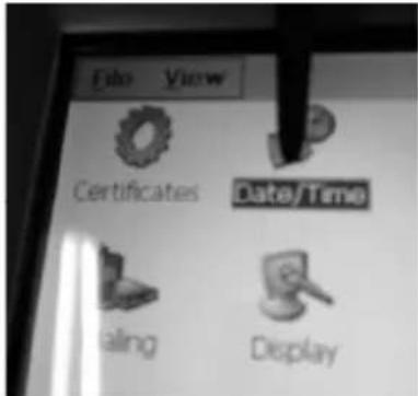
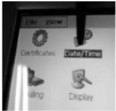
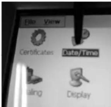
3.6 Set date and time

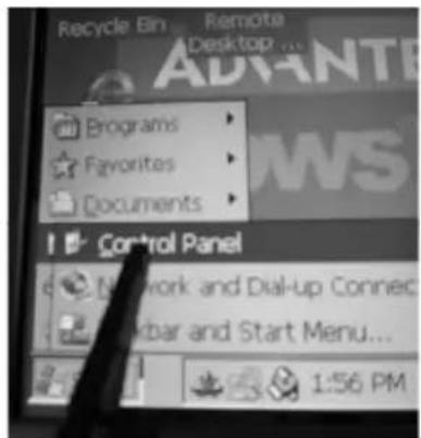
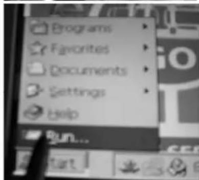
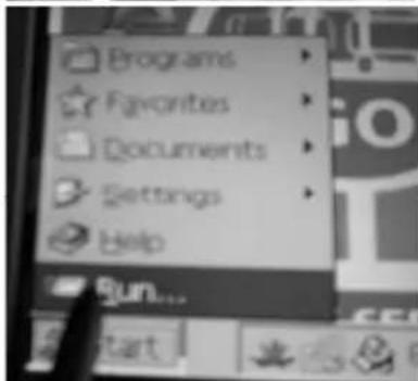
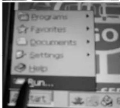
→ Close the program by clicking briefly in the upper left corner.
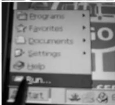
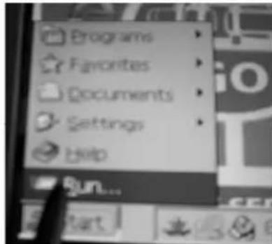
→ Press Start, Setting and then Control Panel.
The taskbar is hidden and can be called back up by pressing on the lower left corner.
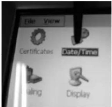
→ Click Date/Time.
→ Set up the entry form by touching and dragging the date/time bar. Select the appropriate time zone or enter the current time.
Attention! Pay attention to AM/PM! 1:58:09 PM = 13:58:09 / 1:58:09 AM = 01:58:09
→ Confirm with „Apply“ and „OK“. Close the control panel with X.


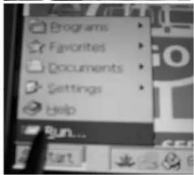
→ Press the „Start“ and „Run“ buttons
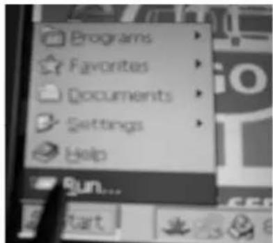
On the keyboard that appears, enter reboot and press "OK". The PC restarts.
![Type the name of a program, folder, or document, and Windows will open it for v reboot OK Cancel Brow Funkey 1 2 3 4 5 6 7 8 9 0 - = + q w e r t y u i o p [ ] p a s d f g h j k l ; ' ft z x c v n m , . / ← äü ' <|](/content/2026/04/733840/images/516792a484493c37a6681d70e5053caeb0959709e647d735f94a7e777283856c.jpg)
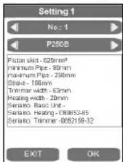
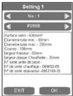
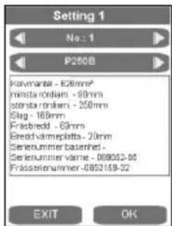
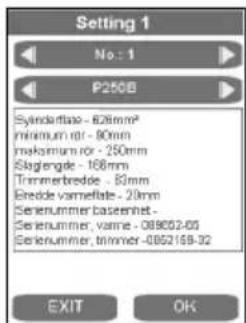
3.7 Setting up or selecting machine configurations
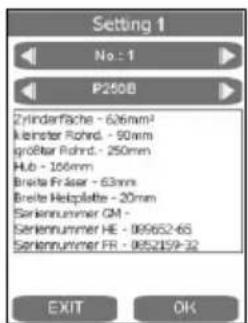
To select or set up machine configurations, press the SETTINGS button.
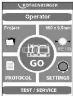
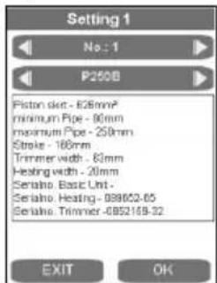
The desired machine configuration can be selected using the arrow keys.
To set up a new configuration, use the right arrow key to start the next number, such as 2.
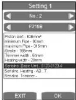

Pressing on the corresponding display field brings up the entry form. The data can be deleted with DEL and reentered. These data are later placed into the log.
3.8 Error messages
General:
| Error message Troubleshooting | |
| After milling, during drag pressure measurement, the basic machine moves up instead of together, or does not move | 1) Call up the “TEST/SERVICE” window, and check “Position” – must be < 10 |
| 2) With the program “First commissioning”, set the position of the position sensor | Check the generator output |
Touch PC and log:
| Error message Description Troubleshooting | ||
| Code 1 Equalization | pressure too high Test the hydra | aulics without the basic machine, build up 100 bar, compare the actual value with the target value – the difference should be less than 5 bar |
| Code 2 Equalization | pressure too low | |
| Code 4 Warm-up | pressure too high | |
| Code 8 Warm-up | pressure too low | |
| Code 16 Warm-up | time too long | |
| Code 32 Warm-up | time too short | |
| Code 64 Changeover | time too long | |
| Code 128 Pressure | build-up time too long | |
| Code 256 Joining | pressure too high | |
| Code 512 Joining | pressure too low | |
| Code 1024 Joining | time too short | |
| Code 2048 Heating | element temperature too low | 1) Compare the temperature of the heating element with what is shown on the display2) Set parameter P002 to “0”3) Protect the heating plate from strong wind |
| Code 4096 Interruption by operator | ||
| Code 8192 Ambient temperature not measured | ||
| Code 16384 Joining | distance not adhered to | |
| Code 32768 Heating | element not removed | |
| Code 65536 Second cooling time not adhered to | ||
| Code 131072 Heating element temperature too high | Compare the temperature of the heating element with what is shown on the display | |
| Error Dataline 2.0 exe | Call up the “default” file in the middle of the screen:1) Close the “GO” screen2) Double click on “default”3) Restart the machine | |
Controls:
| Error message Description Troubleshooting | ||
| SER Service date reached, service due | Have service performed | |
| ERR1 Absolute pressure not reached Check oil level | , check pressure sensor, defective valve, defective motor | |
| PE-2 Pressure sensor -24V defective Replace pressure sensor | ||
| ERR5 Oil temperature 70°C – Stop! Wait until the oil temperature is below 50°C | ||
| HE-1 Heating element not connected, sensor break | Replace the sensor | |
| HE-0 Heating element too hot Remeasure temperature, replace sensor | ||
| HE-2 Heating element too cold Remeasure temperature, replace sensor | ||
4 Care and Maintenance
To ensure that the welding machine functions properly, observe the following maintenance recommendations:
- The guide rods must be kept free of dirt and grime. Replace guide rods whenever surface shows signs of erosion or damage, otherwise hydraulic system may loose pressure.
- To achieve perfect welding results, it is essential to keep the heating plate clean. If the surface is damaged or shows signs of erosion, the surface must be recoated or replaced. Material residues on the heating plate surface reduces the non-sticking properties of the coating. Remove all residues with non-linting paper and detergent with one Ethanol content >99.8% (according to DVS 2207) (heating plate must be cool!).
- Change hydraulic oil (HLP – 46, no.: 53649) every twelve months.
- To avoid malfunctions, regularly check the hydraulic unit for leaks, proper fit of connections as well as the power cable for signs of damage or wear.
- Protect the fast-on couplings on both the hydraulic unit as well as the hydraulic hoses from dirt and grime. Remove any dirt or foreign objects prior to connecting.
- The trimmer unit is equipped with two bi-directional blades. Rotate or replace blades whenever trimming performance is no longer up to expectations.
- Always ensure that the pipe and workpiece ends, in particular the butt surfaces are clean. Dirt or other foreign substances will shorten the serviceable life of the blades considerably.

Pursuant to welding guidelines the welding machine must be inspected annually by the manufacturer or an authorized service workshop. Machines subjected to above average use or strain should be inspected at shorter intervals!
5 Accessories
You can find suitable accessories in the main catalog or at www.rothenberger.com
6 Customer service
The ROTHENBERGER service locations are available to help you (see listing in catalog or online) and replacement parts and service are also available through these same service locations. Order your accessories and spare parts from your specialist retailer or using RO SERVICE+ online: 📞 + 49 (0) 61 95/ 800 8200 📄 + 49 (0) 61 95/ 800 7491 ✉ service@rothenberger.com - www.rothenberger.com
7 Disposal
Components of the unit are recyclable material and should be put to recycling. For this purpose registered and certified recycling companies are available. For an environmental friendly disposal of the non-recyclable parts (e.g. electronic waste) please contact your local waste disposal authority.
Do not dispose of power tools and batteries/rechargeable batteries into household waste.
For EU countries only: According to the Directive 2012/19/EU on waste electrical and electronic equipment and its transposition into national law, power tools that are no longer usable, and, according to the Directive 2006/66/EC, defective or drained batteries must be collected separately and disposed of in an environmentally correct manner.
Only for United Kingdom: According to The Waste Electrical and Electronic Equipment Regulations 2013 (SI 2013/3113) (as amended) and the Waste Batteries and Accumulators Regulations 2009 (SI 2009/890) (as amended), products that are no longer usable must be collected separately and disposed of in an environmentally friendly manner.
∅ ≤ 355mm = 0,5mm, ∅ 400... < 630mm = 1,0mm, ∅ 630... < 800mm = 1,3mm.


service@rothenberger.com - www.rothenberger.com
∅ ≤ 355mm = 0,5mm, ∅ 400... < 630mm = 1,0mm, ∅ 630... < 800mm = 1,3mm.
∅ ≤ 355mm = 0,5mm, ∅ 400... < 630mm = 1,0mm, ∅ 630... < 800mm = 1,3mm.
service@rothenberger.com - www.rothenberger.com
7 Eliminación
Hoogte (mm)....900....900....1500....1500
∅ ≤ 355mm = 0,5mm, ∅ 400... < 630mm = 1,0mm, ∅ 630... < 800mm = 1,3mm.
∅ ≤ 355mm = 0,5mm, ∅ 400... < 630mm = 1,0mm, ∅ 630... < 800mm = 1,3mm.


→ Inserir reboot no teclado que surge e premir „OK“, reini- ciar o PC
![Type the name of a program, folder, or document, and windows will open it for your reboot OK Cancel Bsw Funbner 1 2 3 4 5 6 7 8 9 0 - = + q w e r t y u i o p [ ] p a s d f g h j k l ; * ft z x c v n m , . / ← áü \](/content/2026/04/733840/images/aa6e743a14b3e7eb174386047a82b38654704ee4f33ee2a4646e9735cafeaa5f.jpg)
∅ ≤ 355mm = 0,5mm, ∅ 400... < 630mm = 1,0mm, ∅ 630... < 800mm = 1,3mm.


∅ ≤ 355mm = 0,5mm, ∅ 400... < 630mm = 1,0mm, ∅ 630... < 800mm = 1,3mm.
→ Klicka på Date/Time.


→ Trykk tastene „Start“ og „Run“
Leveys (mm)....485....600....900....1060
Korkeus (mm)....415 .... 535.... 800 .... 920
kork. Paino * (SA kg) 59,0 80,2 238,5 323,4
kork. Paino * (VA kg) 61,3 83,8
∅ ≤ 355mm = 0,5mm, ∅ 400... < 630mm = 1,0mm, ∅ 630... < 800mm = 1,3mm.


→ Paina painikkeet „Start“ ja „Run“

Wysokość (mm)....900....900....1500....1500


→ „Start“ ve „Run“ düğmelerine basın

Magasság (mm)....900....900....1500....1500

![Type the name of a program, folder, or document, and Windows will open it for v reboot OK Cancel Brow Funbner 1 2 3 4 5 6 7 8 9 0 - = + g w e r t y u i o p [ ] p a s d f g h j k l ; * ft z x c v n m , . / ← áü '](/content/2026/04/733840/images/ec6d90c4f49561badfefe40565fb0f1dfdc21981f4bcd652a2d9b048bc20e691.jpg)
service@rothenberger.com - www.rothenberger.com
7 Ártalmatlanítás


→ Pritisnite tipki „Start“ in „Run“

→ Na tipkovnici, ki se je pokazala, vnesite reboot in pritisnite „OK“, računalnik se bo zagnal znova
![Type the name of a program, folder, or document, and Windows will open it for v reboot OK Cancel Browse Funliver 1 2 3 4 5 6 7 8 9 0 - = + a q w e r t y u i o p [ ] p a s d f g h j k l ; * ft z x c v n m , . / ← áü ' \](/content/2026/04/733840/images/4a6b90e6443e90231d21b3a874e3d91fb985c7115cfb8604f9e3400155392ee9.jpg)
Výška (mm)....900....900....1500....1500
∅ ≤ 355mm = 0,5mm, ∅ 400... < 630mm = 1,0mm, ∅ 630... < 800mm = 1,3mm.


![Type the name of a program, folder, or document, and Windows will open it for m reboot OK Cancel Browse Runover Runell 1 2 3 4 5 6 7 8 9 0 - = + q w e r t y u i o p [ ] a s d f g h j k l ; * ft z x c v n m , . / ← áü ` \](/content/2026/04/733840/images/1c7545b4ef6b6b3d7fb081b92a0be5c24a77c748cc15ab7d3c4bd39c22106320.jpg)
B (MM)....900....900....1500....1500