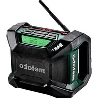
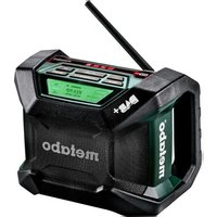
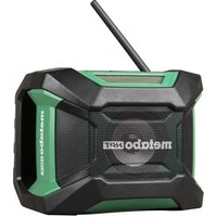
RC 14.4-18 - Radio METABO - Free user manual and instructions
Find the device manual for free RC 14.4-18 METABO in PDF.

| Product Type | Jobsite radio with integrated charger |
| Brand | Metabo |
| Model | RC 14.4-18 |
| Dimensions (L x H x D) | 262 x 385 x 271 mm |
| Weight | Approx. 5.3 kg (without battery) |
| Mains power | AC 220-240 V / 120 V, 50/60 Hz |
| Battery power | Li-Ion 14.4-18 V (Metabo Li-Power) |
| DC power | DC 12 V (9-14 V), center positive plug, ø 5.5 mm |
| Frequency ranges | FM 87.50-108 MHz ; AM (MW) 520-1710 kHz (10 kHz) / 522-1629 kHz (9 kHz) |
| Output power | 8 W (on 14.4 V battery) / 6 W (on mains) |
| Speaker | 6.5" (16.5 cm), 8 ohms, 15 W |
| Integrated charger | For Metabo Li-Ion batteries 14.4-18 V, charging current 2.5 A |
| Typical charging time | 30 min (1.3 Ah) to 115 min (5.2 Ah) |
| Radio functions | Automatic search, manual selection, 5 presets per band |
| Alarm / Wake-up | Radio alarm and progressive sound alarm (HWS) |
| Sleep function | Adjustable timer (15, 30, 45, 60, 90, 120 min) |
| Inputs / Outputs | AUX IN jack (3.5 mm), headphone jack (3.5 mm), DC 5 V/500 mA output, AC OUT socket (8 A max) |
| Lighting | Long-life LED on the front |
| Protection rating | Do not expose to rain or moisture |
| Safety battery | 2 AA batteries (not included) for settings backup |
| Supplied accessories | AUX IN cable, adapter for Sony Ericsson (depending on model) |
| Maintenance | Clean with a dry cloth; repairs by qualified personnel |
| Warranty | Consult Metabo customer service |
Frequently Asked Questions - RC 14.4-18 METABO
User questions about RC 14.4-18 METABO
0 question about this device. Answer the ones you know or ask your own.
Ask a new question about this device
Download the instructions for your Radio in PDF format for free! Find your manual RC 14.4-18 - METABO and take your electronic device back in hand. On this page are published all the documents necessary for the use of your device. RC 14.4-18 by METABO.
USER MANUAL RC 14.4-18 METABO
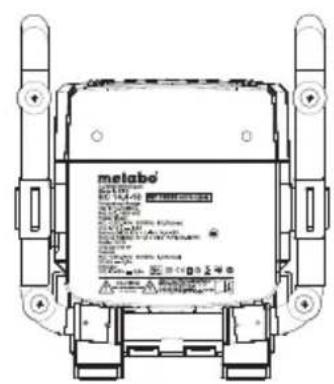
natural_image
Black Metabo radio device with digital display and antenna (no readable text or symbols on device body)
(D) Originalbetriebsanleitung.... 2
ENG Original instructions.... 16
(F) Notice originale.... 30
NL Oorspronkelijke gebruiksaanwijzing... 44
IT Istruzioni originali.... 58
ES Manual original 72
PT Manual original 86
SV Bruksanvisning i original.... 100
FIN Alkuperäiset ohjeet 113
NO Original bruksanvisning 127
④ Original brugsanvisning 141
POL Instrukcją oryginalną 155
① Πρωτότυπο οδηγιών χρήσης ...... 170
HU Eredeti használati utasítás.... 185
RU Оригинальное руководство по эксплуатации. 199
natural_image
Technical line drawing of a mechanical device with a hand pointing to the screen (no text or symbols present)
natural_image
Technical line drawing of a mechanical device with a hand pointing to a component (no text or symbols present)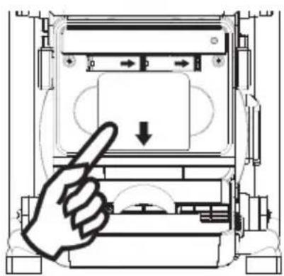
natural_image
Diagram of a hand pressing a button on a device panel (no text or symbols visible)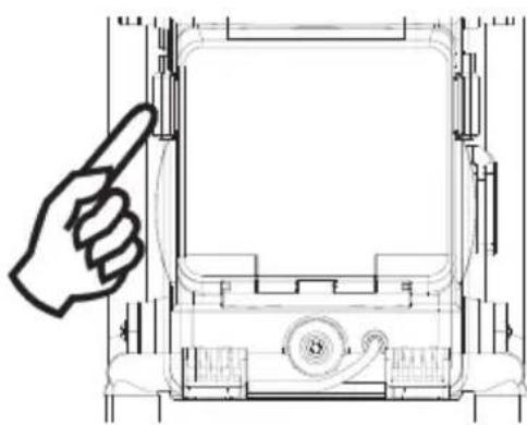
natural_image
Technical line drawing of a mechanical device with a hand pointing to the front panel (no text or symbols)1. Batteriebetrieb
Director Product Engineering & Quality
Responsible Person for Documentation
© 2011 Metabowerke GmbH, 72622 Nürtingen, Germany
IMPORTANT SAFETY INSTRUCTIONS

Before using the Radio Charger, carefully read through and familiarise yourself with all the enclosed safety information and the Operating Instructions. Keep all enclosed documentation for future reference, and pass on your Radio Charger only together with this documentation.
- Read these instructions.
- Keep these instructions.
- Heed all warnings.
- Follow all instructions.
- Do not use this apparatus near water.
- Clean only with dry cloth.
- Do not install near any heat sources such as radiators, heat registers, stoves, or other apparatus (including amplifiers) that produce heat. Do not expose to open fire.
- Do not defeat the safety purpose of the polarized or grounding-type plug. A polarized plug has two blades with one wider than the other. A grounding type plug has two blades and a third grounding prong. The wide blade or the third prong are provided for your safety. If the provided plug does not fit into your outlet, consult an electrician for replacement of the obsolete outlet.
- Protect the power cord from being walked on or pinched particularly at plugs, convenience receptacles, and the point where they exit from the apparatus.
- Only use attachments/accessories specified by the manufacturer.
- Unplug this apparatus during lightning storms, before any adjustments or servicing, or when unused for long periods of time.
- Refer all servicing to qualified service personnel, only with original spare parts. Servicing is required when the apparatus has been damaged in any way, such as power-supply cord or plug is damaged, liquid has been spilled or objects have fallen into the apparatus, the apparatus has been exposed to rain or moisture, does not operate normally, or has been dropped.
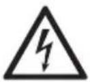
- To reduce the risk of fire or electric shock, do not expose this appliance to rain or moisture.
- The Shock Hazard Marking and Associated Graphical Symbol is provided on the bottom panel of unit.
-
Apparatus shall not be exposed to dripping or splashing and no objects filled with liquids, shall not be placed on the apparatus.
-
Equipment-dependent: Please confirm that the maximum power loading of the AC outlet does not exceed the rated output power of 8A/250V. Never use the AC outlet in a wet or moist environment, to avoid electronic shock. The AC outlet has a series breaker to protect from over loading. If the breaker has protected the AC outlet, you have to remove all of output loads away from the AC outlet and then wait for the breaker to recover (within 3\~5 minutes). The AC outlet includes a ground lead. The AC plug of Radio must be plugged with an AC power source which has this ground lead. This breaker protects the AC outlet only, not for radio and charger.
17. Power supply
Before plugging in, check to see that the rated mains voltage and mains frequency, as specified on the rating label, match your power supply. The machine must only be connected to a socket that has been properly earthed in accordance with regulations. Regularly check the cable and the plug on the power tool and have them repaired by the Metabo after sales service team if damaged. If an extension cord is needed, it must be a three-core lead with a protective (earth) contactor that is properly connected to both the plug and the coupler of the cord. When working outdoors, only use the correspondingly marked extension cable approved for this purpose. Regularly check extension cables and replace if damaged. Extension cables must be suitable for the power rating (see Technical Specifications). If using a roll of cable, always unroll the cable completely.
18.

Protect battery packs from water and moisture!
Do not expose battery packs to naked flame!
Do not use faulty or deformed battery packs!
Do not open battery packs!
Do not touch or short-circuit battery packs!

Slightly acidic, flammable fluid may leak from defective Li-ion battery packs!
If battery fluid leaks out and comes into contact with your skin, rinse immediately with plenty of water. If battery fluid leaks out and comes into contact with your eyes, wash them with clean water and seek medical attention immediately.
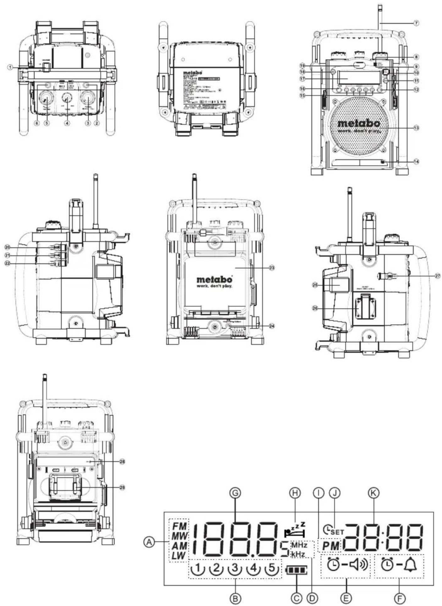
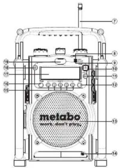
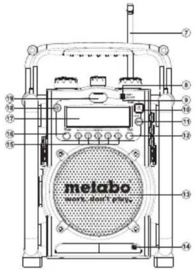
Control
① Charger Switch
② Warning Display of Charger
③ Tuning Control/Time Set/Station Scan
④ Tone Control
⑤ Volume Control
⑥ Operating Indicator of Charger
⑦ FM Antenna
⑧ Aux In LED Indicator
⑨ DC Out LED Indicator
10 Power Button
⑪ Band Selection
⑫ Buzzer Alarm
13 Speaker
14 Buzzer
15 Preset Stations
16 Radio Alarm
17 LCD Display
18 Light Switch
19 Light
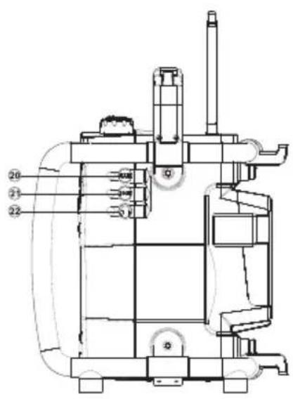
20 Aux In Socket
②1 DC Output Socket
22 Headphone Socket
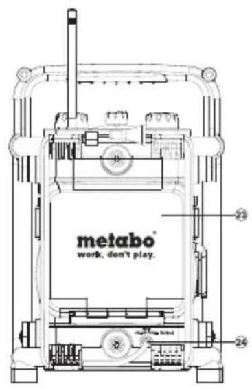
23 Battery Compartment
24 Power Cord
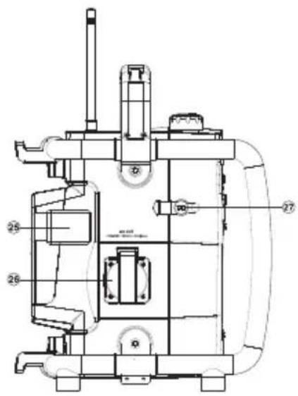
25 Battery Compartment Cover Clip
26 AC Out (equipment-dependent)
27 DC Input Socket
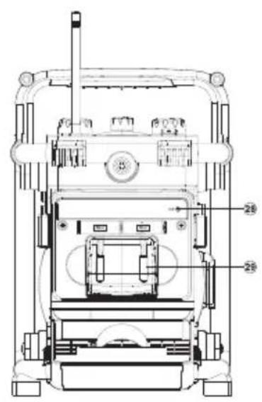
28 Aux In Cable with Plug
③0 Lithium Battery (not included in delivery)
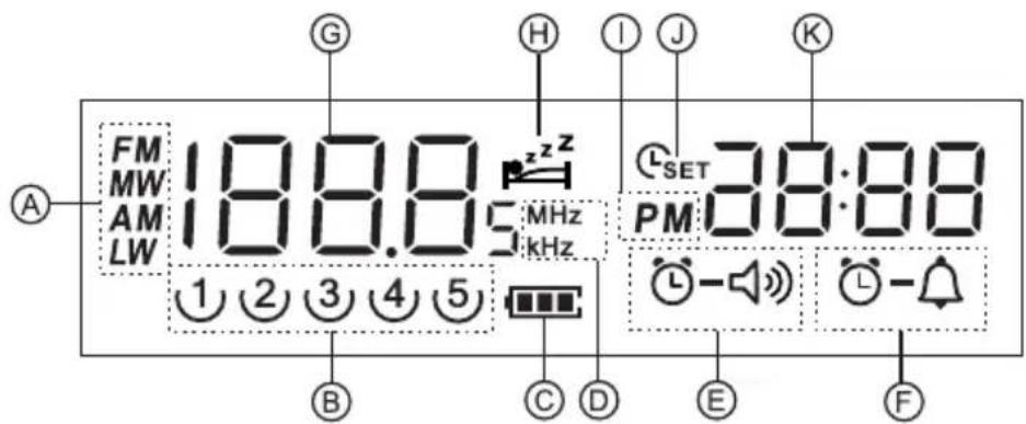
LCD Display
A Band Indicator
B Preset Stations
c Battery Power
D Frequency unit
E Radio Alarm Settings
F HWS Buzzer Alarm
G Frequency
H Sleep and Snooze Status
① PM Display
J Time Set
K Clock
Power the radio
Note:
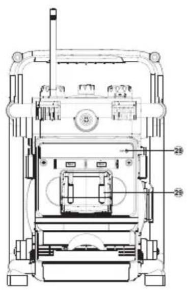
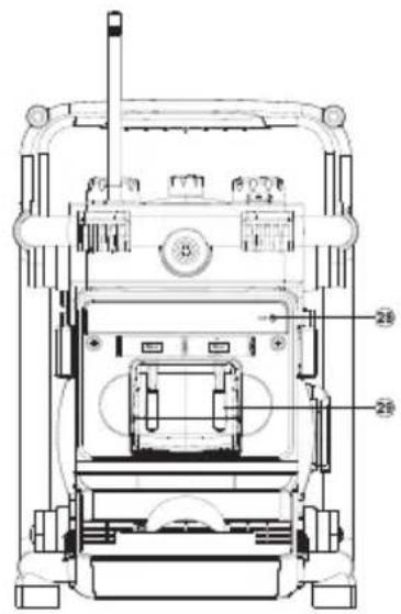
Insert back up battery prior to main batteries. Back up battery is to back up the preset stations and also clock. It is necessary to insert back up battery (2 x UM-3 1.5V, not supplied) for memory back up even if you use AC power only. Without the back up battery, time and preset station will be lost if the AC power cord is removed from AC outlet or during AC power failure.
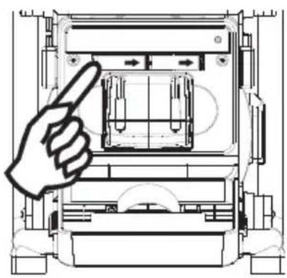
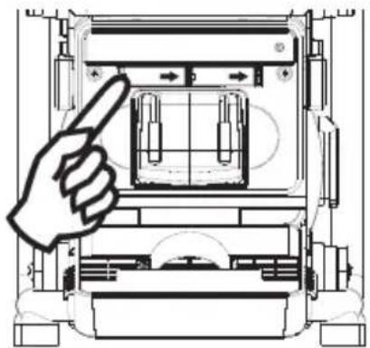
Back up battery compartment is located inside the main battery compartment. Insert 2 x AA size (UM-3) battery and ensure the battery is inserted in accordance with the diagram shown.
1.
natural_image
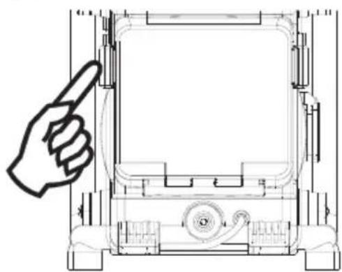
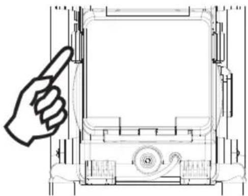
Technical line drawing of a mechanical device with a hand pointing to the top view (no text or symbols present)2.
natural_image
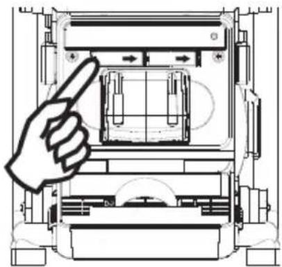
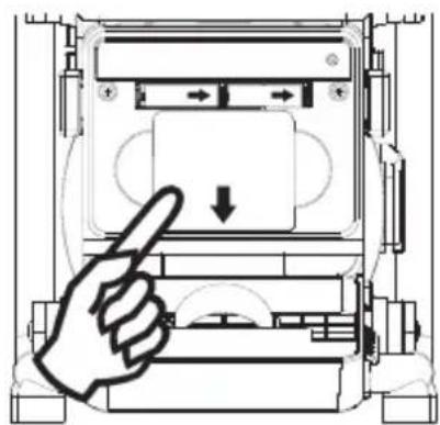
Technical line drawing of a mechanical device with a hand pointing to a component (no text or symbols)3.
natural_image
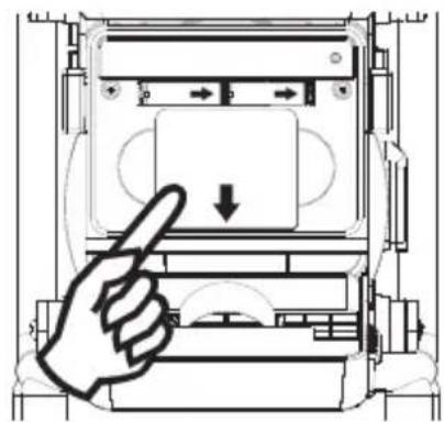
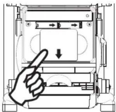
Diagram of a hand pressing down on a device component with directional arrows (no text or symbols)4.
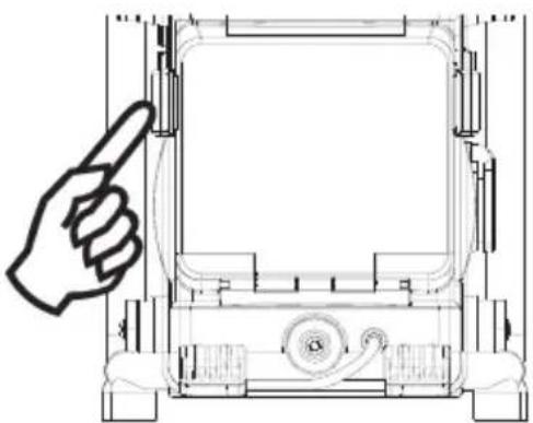
natural_image
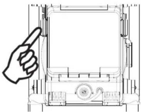
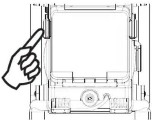
Technical line drawing of a mechanical device with a hand pointing to the top view (no text or symbols present)1. Battery operation
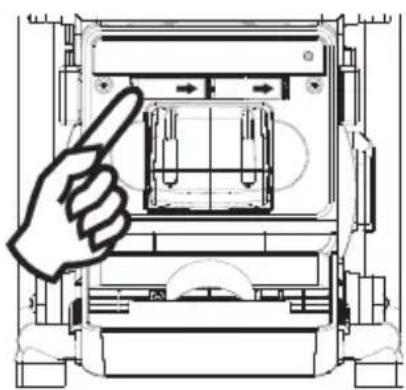
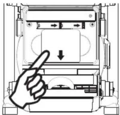
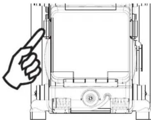
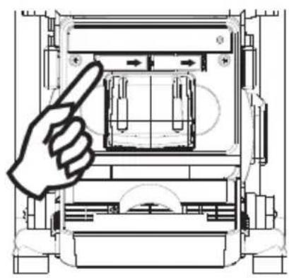
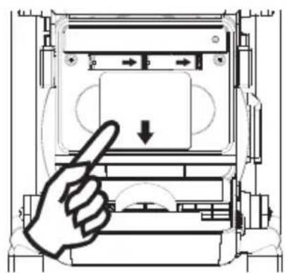
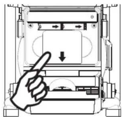
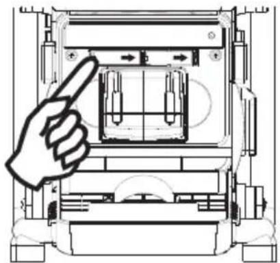
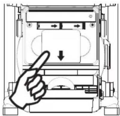
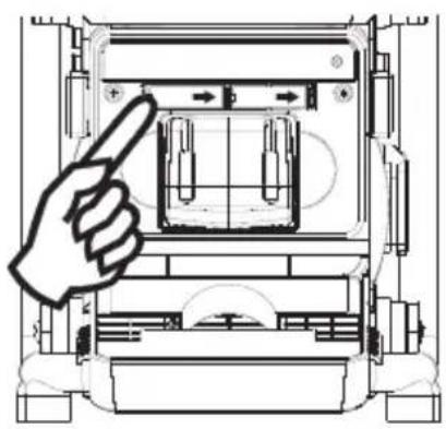
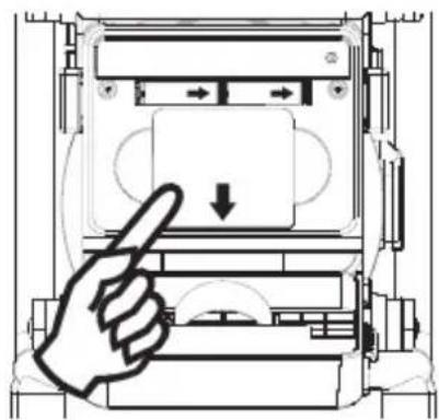
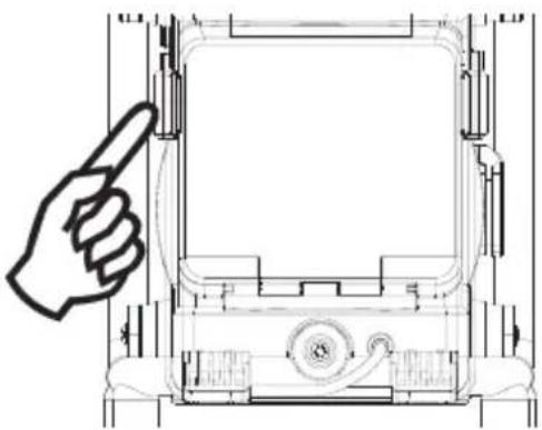
To insert the batteries, first release the cover by unlocking the clips. Insert Metabo Li-ion (14.4V to 18V slide style batteries) battery into the compartment. Ensure the battery is inserted in accordance with the diagram shown. Close the battery cover and lock up clips back into place. If the radio is not to be used for any extended period of time, it is recommended that the battery is removed from the radio. Only Metabo Li-Power Compact, Li-Power Plus and Li-Power Extreme batteries with 14.4 or 18V are suitable to operate the radio by battery. There is a danger of fire and explosion if you try to operate with batteries from other manufacturers.
2. AC operation
Before plugging the mains cord into the AC socket, make sure the voltage is correct. If you have batteries in the radio and use the AC power cord, the batteries will automatically be disconnected.
Release cable clip and pull cable from rack rotationally.
3. Powered via DC IN socket
The radio can be also powered via the DC IN socket which can allow 9-14 Volt DC. This socket is designed to be powered by the vehicle or the boat so you can take the radio with you outdoors or on the boat. An additional cigarette lighter cable is required (not supplied) for this device.
Note:
Be carefully not to reverse the electrode +/- of the input DC power and not to input a voltage much higher than 16V, otherwise that could damage inner circuitry.
Setting the clock
- Clock can be set either the radio is power on or off.
- Display will show “- : - -” when the batteries are installed or when the radio is connected to the mains supply.
- Press in Tuning control (Time Set) knob for more than 2 seconds, display will flash time set symbol and also the hour digits, followed by a beep.
- Rotary Tuning Control (Time Set) knob to set the required hours.
- Press in Tuning control knob, the minute digits will flash.
- Rotary Tuning Control button to set required minute.
- Press in Tuning Control button to complete time setting.
Operating the radio
This radio is equipped with three tuning methods – Scan tuning, Manual tuning and Memory presets recall.
Scan Tuning
- Press the Power button to turn on the radio.
- Select the required waveband by pressing the Band button. For FM band, be sure to screw in the rubber FM antenna properly to get the best reception.
For MW (AM) band, rotate the radio to get the best signal, and turn off Charger switch on the top to cut down charging battery function in order to minimise interference from electric circuit when necessary. - Press and release Tuning Control /Time Set /Scan knob (long press the knob more than 2 seconds will activate time setting), the radio will up search and stop automatically when it finds a radio station. Press the Scan button again to pick up the found station.
Note:
The radio will continue to search next available stations if you do not press Scan button again when it finds a radio station.
-
Rotate the Volume Control and Tone Control to get required sound level.
-
To turn off the radio, press the Power button. Display will show OFF.
Manual tuning
- Press the Power button to turn on the radio.
- Select the required waveband by pressing the Band button. Adjust the antenna as described above.
-
A single press on either rotate the Tuning Control knob will change the frequency in the following increments:
FM: 50 or 100 kHz
MW (AM): 9 or 10 kHz -
Rotate the Volume Control and Tone Control to get required sound level.
-
To turn off the radio, press the Power button. Display will show OFF.
Storing stations in preset memories
There are 5 memory presets for each waveband.
- Press the Power button to turn on the radio.
- Tune to required station using one of the methods previously described.
- Press and release the required Preset button.
The preset number and station frequency will appear in the display.
-
Repeat this procedure for the remaining presets.
-
Stations stored in preset memories can be overwritten by following above procedures.
Recalling stations from preset memories
- Press the Power button to turn on the radio.
- Select the required waveband.
- Momentarily press the required Preset button, the preset number and station frequency will appear in the display.
Setting the radio alarm
When the radio alarm is selected, the radio will turn on and play the chosen radio station at the chosen alarm time. The radio alarm will continue for one hour unless turned off by pressing the Power button. Press the Power button whilst the alarm is activated will cancel the alarm for 24 hours.
Note:
Radio alarm can be activated only until both radio alarm time and radio alarmed station are set. Radio alarm will be automatically switched to Buzzer alarm when the radio is in low battery status or the selected radio alarm station signal is too weak.
a. Setting radio alarm time:
- The radio alarm can be set either radio is on or off.
- Press and release radio alarm button : the radio alarm signal will flash.
- During radio alarm flashing, press Tuning control/Scan/Time Set knob for more than 2 seconds followed by a beep tone.
- Display Hour flashes. Rotate Tuning Control knob to select the hour then press in Tuning control/Scan/Time Set knob again to confirm hour setting.
- Follow same procedure of setting hour to set required minute. Press Tuning Control/Scan/Time Set knob again to complete alarm time setting.
b. Setting radio alarmed station:
- During setting radio alarm time and radio alarm symbol is flashing, press Band button to activate the radio to select required wake-up band and station by manual tuning and recall preset stations.
- When above radio alarm time and station are set, press and hold radio button for 2 seconds followed by a beep tone to switched alarm on or off. Display will show 📋-10 when radio alarm is set.
Note: If new radio alarm station is not selected, it will select the last alarm station.
Setting the HWS (Humane Wake System) buzzer alarm
A beep tone will activate when selecting the HWS alarm.
The alarm beep will increase in volume every 15 seconds for one minute followed by one minute silence before repeating the cycle.
The HWS buzzer alarm will sound for one hour until turning off by pressing the Power button.
Press the Power button whilst the alarm is activated will cancel the alarm for 24 hours.
- The HWS buzzer alarm can be set either radio is on or off.
- Press and release the HWS buzzer alarm button ⏻, the symbol ⚫ will fl ash.
- During radio alarm flashing, press Tuning control/Scan/Time Set knob for more than 2 seconds followed by a beep tone. Display Hour digit will flash.
- Rotate Tuning Control knob to select required alarm hour, then press in Tuning Control knob again. The minute digit will then flash.
- Rotate Tuning Control knob to select required alarmed minute the press in Tuning Control knob to complete alarm setting.
- Press and hold down HWS buzzer alarm button ⏻ for more than 2 seconds followed by a beep tone to switch on or off the alarm.
Display will appear 📋-△ when HWS buzzer alarm has been set.
Snooze function
- Whilst the alarm is activated, press any buttons, except the Power button, will activate the snooze function. The radio or HWS buzzer alarm will be silenced with interval of 5 minutes.
- The display will flash both the snooze symbol z^z^z and the alarm symbol. The snooze function can repeatedly during the 1 hour that the alarms are active.
Sleep function
The sleep timer will automatically switch off the radio after a preset time has elapsed.
-
Press and continue to hold down the Power button for more than 2 seconds, followed by a beep tone, display will cycle through the available sleep times in the order 60-45-30-15-120-90-60. Release the Power button when the required sleep time appears in the display. The symbol will appear in the display and the radio will play the last station selected.
-
To cancel the sleep function, press the Power button, the symbol will disappear and radio is off.
Display backlight
Press any buttons will illuminate the LCD display for approx. 15 seconds. During scanning stations and alarm activated, will also automatically illuminate the display. The Display will be permanently illuminated during using AC power source.
Setting tuning step
Tuning steps on some countries are different from where you purchase the radio. If you buy the radio in Europe and intend to use in Northern America or some Southern American countries, you may have to adjust tuning step so the radio may continue to serve you well. While radio is switched off, long press Step/Band button for more than 2 seconds will first show current FM tuning step.
Continue pressing Step/Band button for approx. another 5 seconds until display FM and 50 kHz (tuning step) flashing followed by a beep. By rotate Tuning Control knob, you may adjust to 100 kHz per tuning step.
After FM tuning step is reset, pressing Step/Band button again, display will show MW and flash 9 kHz. By rotate Tuning Control knob, you may adjust to 100 kHz per tuning step. Complete the setting by pressing Step/Band button.
Aux and Headphones sockets
- There are two Aux. One is Aux socket on the right side of your radio and another is Aux plug in the battery compartment. Aux is for the use with a tape recorder/mini disc/mp3 player/CD player or any other equipment that can provide a line level signal. Connecting external device to Aux will automatically mute the internal signal. The Volume and Tone control can be used to adjust sound level.
Note: Aux-1 LED will be on only when Aux socket on the right side of your radio is connected. - The Headphone socket (3.5 mm) located on the right side of your radio is for use with either headphones or an earphone. Inserting the headphone plug automatically mutes the internal loudspeaker. If the alarm radio or buzzer is expected for warning or wakening, the headphone has to be unplugged.
DC out – charge your mobile phone
DC OUT functions only when the radio is switched off.
Suitable for phones with 3.6 – 4.8 Volt batteries. Please read instruction manual of your mobile phone.
Connect the charging cable (not included) in delivery to the DC out. For Nokia phones you can connect your phone directly to this cable. For Sony Ericsson mobile phones, connect the supplied plug adaptor to go with the mobile phone connection. For other brand mobile phones, you can source from mobile phone accessory stores to get the suitable plugs.
Light
Your radio is fitted with a long life LED light located on the front of your radio. The light may be switched on and off by gently pressing the Light button.
AC Out (equipment-dependent)
The AC OUT socket is active only when the radio is mains-operated and not when it is battery-operated.
Open AC Out cover and insert the plug of external electronic device into socket. The maximum permitted current consumption must not exceed 8A.FM built-in removable curved spring antenna.
Technical Specifications
Frequency Coverage:
FM 87.50 – 108 MHz
AM (MW)
520 - 1710 kHz (10 kHz)
522 - 1629 kHz (9 kHz)
AC Power:
AC 120V/50Hz/60Hz/10A(Max.) (US)
AC 220-240V/50Hz/60Hz/10A(Max.) (CE/UK/AUS)
Batteries:
Lithium-ion 14.4V-18V (only Metabo Li-Power Compact, Li-Power Plus and Li-Power Extreme battery packs with 14.4 or 18V are suitable to operate the radio by battery)
DC IN:
12V/1A center pin positive (operational voltage 9-14V) 5.5 mm in diameter.
Output Power:
8W 10% T.H.D. @ 100 Hz @ DC battery 14.4V
6W 10% T.H.D. @ 100 Hz @ AC 230V or 120V (equipment-dependent)
Headphones socket: 3.5 mm diameter, stereo jack, monaural output
Output power: 4 mW + 4 mW
Aux in socket: 3.5 mm diameter, stereo jack to be mixed as monaural
Input sensitivity: 360m Vrms at output 6W @ 100 Hz
Input impedance: 47 kohm
DC Out: 5V 500 mA
AC Out: 120V (USA) / 230V (EU/GB) / max. 8A
Speaker unit: 6.5 inches 8 ohm 15W, full range
Internal Antenna system:
AM built-in ferrite aerial
FM built-in removable bended spring antenna
LED illuminator: 3 x white LED
Dimension: 262x385x271 mm
Weight: approx. 5.3 kgs (not including battery pack)
If at any time in the future you should need to dispose of this product please note that: Waste electrical products should not be disposed of with household waste. Please recycle where facilities exist. Check with your Local Authority or retailer for recycling advice. (Waste Electrical and Electronic Equipment Directive)
Battery charger
1. Declaration of Conformity
We, being solely responsible, hereby declare that this product conforms to the following standards: EN 60335 in accordance with the Directives 2006/95/EG, 2004/108/EG.
CE

Volker Siegle
Director Product Engineering & Quality
Responsible Person for Documentation
© 2011 Metabowerke GmbH, 72622 Nürtingen, Germany
2. Specifi ed Use
The charger is only suitable for charging Metabo battery packs.
This tool is not designed for use by persons (including children) with physical, sensory or mental disabilities, or with insufficient experience and/or knowledge, unless they are supervised by a person responsible for their safety, or have received instructions on how to use the tool by this person.
The Radio Charger is only suitable for charging Li-ion battery packs (14,4 V - 18 V, 1.1 Ah - 5.2 Ah, 4 - 5 cells).

Never attempt to charge batteries that are not rechargeable.
Danger of explosion!
The user bears sole responsibility for any damage caused by improper use.
Generally accepted accident-prevention regulations and accompanying safety instructions should be observed.
3. Special Safety Instructions

For your own protection and for the protection of your radio pay attention to all parts of the text that are marked with this symbol!
Danger - electrical voltage!

Slightly acidic, flammable fluid may leak from defective Li-ion battery packs!
If battery fluid leaks out and comes into contact with your skin, rinse immediately with plenty of water. If battery fluid leaks out and comes into contact with your eyes, wash them with clean water and seek medical attention immediately.
Do not recharge a fully charged battery pack!

Only use the charger indoors.

Protect the charger from moisture.
Children should be supervised to ensure that they do not play with the tool.
Keep children away from the battery charger and the working area!
Keep your battery charger out of reach of children!
Pull out the mains plug immediately if the battery charger starts to smoke or flames emerge!
Do not use faulty battery packs.
4. Commissioning

Before plugging in, check that the rated mains voltage and mains frequency, as stated on the rating label, match with your power supply.

Before commissioning the charger, ensure that the air slots are free. Minimum distance to other objects is 5 cm.
4.1 Self-test
Insert mains plug.
The warning display (2) and the operating indicator (6) light up one after the other for approx. 1 second and the installed fan runs for approx. 5 seconds.
5. Use
5.1 Changing battery pack
Push the battery pack completely to the stop on the sliding seat.

The operating indicator (6) fl ashes.
Note:
To have the charge level displayed on Li-ion battery packs (with 14.4 V, 18 V), first take the battery pack out of the charger and then press the button on the battery pack.
5.2 Conservation charge
Once the charging process has finished, the battery charger automatically switches to conservation mode.
The battery pack can remain in the battery charger and is therefore always ready for use. However, never leave the battery pack in a disconnected battery charger because of the possibility of exhaustive discharge and damage to the battery cells.

The operating indicator (6) lights up continuously.
6. Fault
6.1 Warning display (2) lights up continuously

Battery pack is not charged. Temperature too high/too low. When the temperature of the battery pack is between 0 °C and 50 °C, the charging process begins automatically.
6.2 Warning display (2) fl ashes

- Battery pack is defective. Remove the battery pack immediately from the charger.
- The battery pack was not pushed correctly onto the sliding seat (2).
See section 5.1.
7. Repairs
Repairs to the radio must only be carried out by qualified electricians.
If the mains connection cable of this tool is damaged, in order to prevent endangering personnel and property it must be replaced by the manufacturer, or the Customer Service of the manufacturer, or a similarly qualified person.
If you have Metabo devices that require repairs, please contact your Metabo service centre. For addresses see www.metabo.com.
8. Environmental Protection
Metabo's packaging can be 100% recycled. The used (scrap) radio, charger and accessories contain large amounts of valuable resources and plastics that can be recycled.
These instructions are printed on chlorine-free bleached paper.

Only for EU countries: Never dispose of power tools in your household waste! In accordance with European Guideline 2002/96/EC on used electronic and electric equipment and its implementation in national legal systems, used power tools must be collected separately and handed in for environmentally compatible recycling.
Technical Data of the chargers
 | RC 14.4 - 18 | ||
| U | C | I_c | t |
| 14.4 - 18 V 1.3 | Ah 2.5 A 30 min | ||
| 14.4 - 18 V 1.5 | Ah 2.5 A 35 min | ||
| 18 V 2.2 | Ah 2.5 A 50 min | ||
| 14.4 - 18 V 2.6 | Ah 2.5 A 60 min | ||
| 14.4 - 18 V 3.0 | Ah 2.5 A 70 min | ||
| 14.4 - 18 V 4.0 | Ah 2.5 A 90 min | ||
| 14.4 - 18 V 5.2 | Ah 2.5 A 115 min | ||
U = Voltage ranges of the battery packs
C = Battery pack capacity
I_c = Charging current
t = Charging time^1)
1) Depending on the residual capacity and the temperature of the battery pack, real charging times may deviate from the specifications.
Changes due to technological progress reserved
CONSIGNES IMPORTANTES DE SÉCURITÉ

natural_image
Technical line drawing of a mechanical device with a hand pointing to the top view (no text or symbols present)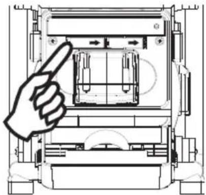
natural_image
Technical line drawing of a mechanical device with a hand pointing to a component (no text or symbols present)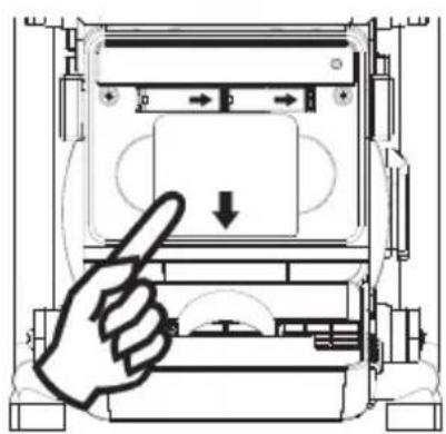
natural_image
Diagram of a hand pressing down on a device component with directional arrows (no text or symbols)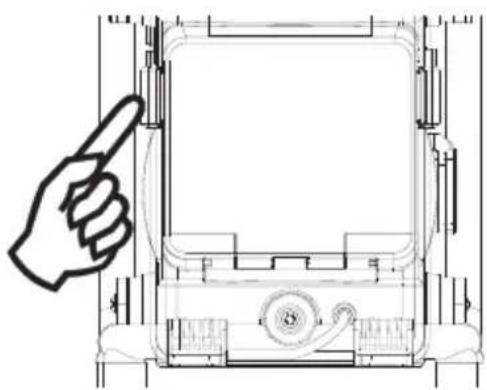
natural_image
Technical line drawing of a mechanical device with a hand pointing to the top view (no text or symbols present)Director Product Engineering & Quality
Responsible Person for Documentation
© 2011 Metabowerke GmbH, 72622 Nürtingen, Germany
natural_image
Technical line drawing of a mechanical device with a hand pointing to the top view (no text or symbols present)2.

natural_image
Technical line drawing of a mechanical device with a hand pointing to a component (no text or symbols)3.
natural_image
Diagram of a hand pointing at a device panel with a downward arrow, no text or symbols present4.
natural_image
Technical line drawing of a mechanical device with a hand pointing to the front panel (no text or symbols)Director Product Engineering & Quality
Responsible Person for Documentation
© 2011 Metabowerke GmbH, 72622 Nürtingen, Germany
C = accupack-capaciteit
I_c = laadstroom
natural_image
Technical line drawing of a mechanical device with a hand pointing to the top view (no text or symbols present)2.

natural_image
Technical line drawing of a mechanical device with a hand pointing to a component (no text or symbols present)3.

natural_image
Diagram of a hand pressing down on a device panel with directional arrows (no text or symbols)4.
natural_image
Technical line drawing of a mechanical device with a hand pointing to the front panel (no text or symbols present)Director Product Engineering & Quality
Responsible Person for Documentation
© 2011 Metabowerke GmbH, 72622 Nürtingen, Germany
natural_image
Technical line drawing of a mechanical device with a hand pointing to the top view (no text or symbols present)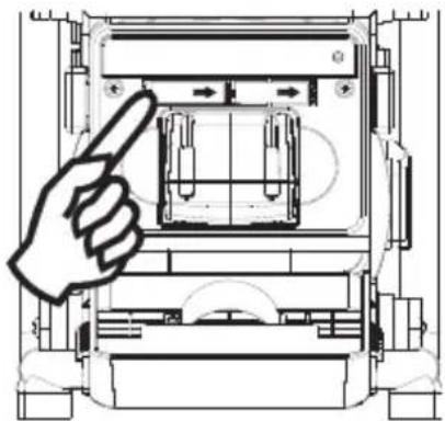
natural_image
Technical line drawing of a mechanical device with a hand pointing to a component (no text or symbols present)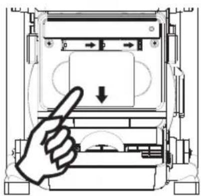
natural_image
Diagram of a hand pressing down on a device component with directional arrows (no text or symbols)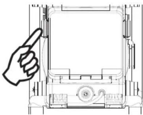
natural_image
Technical line drawing of a mechanical device with a hand pointing to the front panel (no text or symbols)Director Product Engineering & Quality
Responsible Person for Documentation
© 2011 Metabowerke GmbH, 72622 Nürtingen, Germany
2. Uso destinado
natural_image
Technical line drawing of a mechanical device with a hand pointing to the top view (no text or symbols present)2.
natural_image
Technical line drawing of a mechanical device with a hand pointing to a component (no text or symbols)3.
natural_image
Diagram of a hand pressing a button on a device panel (no text or symbols visible)4.

natural_image
Technical line drawing of a mechanical device with a hand pointing to the front panel (no text or symbols present)Visor LED: 3 LEDs brancos
Director Product Engineering & Quality
Responsible Person for Documentation
© 2011 Metabowerke GmbH, 72622 Nürtingen, Germany
natural_image
Technical line drawing of a mechanical device with a hand pointing to the top view (no text or symbols present)2.
natural_image
Technical line drawing of a mechanical device with a hand pointing to a component (no text or symbols)3.
natural_image
Diagram of a hand pressing a button on a device panel (no text or symbols visible)4.
natural_image
Technical line drawing of a mechanical device with a hand pointing to the top view (no text or symbols present)1. Batteridrift
Director Product Engineering & Quality
Responsible Person for Documentation
© 2011 Metabowerke GmbH, 72622 Nürtingen, Germany


Käyttöosat
natural_image
Technical line drawing of a mechanical device with a hand pointing to the front panel (no text or symbols)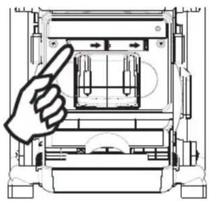
natural_image
Technical line drawing of a mechanical device with a hand pointing to a component (no text or symbols present)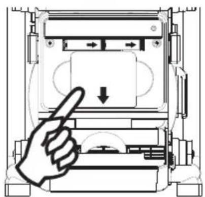
natural_image
Diagram of a hand pressing down on a device component with directional arrows (no text or symbols)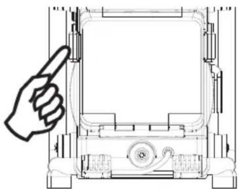
natural_image
Technical line drawing of a mechanical device with a hand pointing to the top view (no text or symbols present)1. Akkukäyttö
MW (AM): 9 tai 10 kHz
Director Product Engineering & Quality
Responsible Person for Documentation
© 2011 Metabowerke GmbH, 72622 Nürtingen, Germany
natural_image
Simple line drawing of an open book with a lowercase 'i' symbol on the right page (no text or labels)


Betjeningselementer
① Lader
② Varselindikator for lader
③ Kanalinnstilling/tidsinnstilling/kanalsøk
④ Tonekontroll
⑤ Volumkontroll
⑥ Driftsindikator for laderen
⑦ FM-antenne
⑧ AUX IN lysdiodeindikator
⑨ DC OUT lysdiodeindikator
⑩ Av/på-knapp
11 Båndvelger
12 Summeralarm
⑬ Høyttaler
14 Summer
15 Kanalminne
16 Radioalarm
17 LCD-display
18 Lysbryter
19 Lys
20 AUX IN-kontakt
21 DC-utgang
^22 Kontakt for hodetelefoner
23 Batterirom
24 Strømkabel
25 Klemme for batteriromdeksel
26 AC OUT (avhengig av utstyret)
27 DC-inngang
28 AUX IN-kabel med plugg
③0 Lithium-ion-batteri (ikke inkludert)
LCD-display
natural_image
Technical line drawing of a mechanical device with a hand pointing to the front panel (no text or symbols)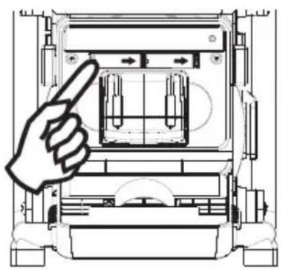
natural_image
Technical line drawing of a mechanical device with a hand pointing to a component (no text or symbols present)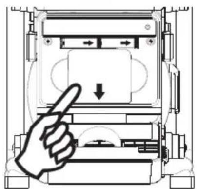
natural_image
Diagram of a hand pressing down on a device component with directional arrows (no text or symbols)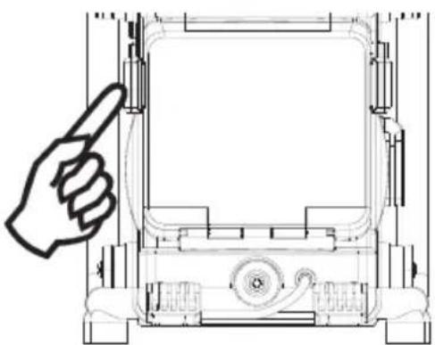
natural_image
Technical line drawing of a mechanical device with a hand pointing to the front panel (no text or symbols)1. Batteridrift
522-1629 kHz (9 kHz)
Vekselstrøm:
AC 120 V / 50 Hz / 60 Hz / 10 A (maks.) (USA)
AC 220-240 V / 50 Hz / 60 Hz / 10 A (maks.) (EU/GB/AUS)
Batterier:
Lithium-ion 14,4 V-18 V (bare Metabo-batteriene Li-Power Compact, Li-Power Plus og
Director Product Engineering & Quality
Responsible Person for Documentation
© 2011 Metabowerke GmbH, 72622 Nürtingen, Germany
2. Forskriftsmessig bruk
Radioen og laderen er kun egnet til lading av Metabo-batterier.
natural_image
Simple line drawing of an open book with a lowercase 'i' symbol on the right page (no text or labels)


Betjeningselementer
natural_image
Technical line drawing of a mechanical device with a hand pointing to the front panel (no text or symbols)2.
natural_image
Technical line drawing of a mechanical device with a hand pointing to a component (no text or symbols present)3.
natural_image
Diagram of a hand pointing at a device component with directional arrows (no text or symbols)4.

natural_image
Technical line drawing of a mechanical device with a hand pointing to the front panel (no text or symbols present)1. Batteridrift
MW (AM): 9 eller 10 kHz
522-1629 kHz (9 kHz)
Vekselstrøm:
AC 120 V/50 Hz/60 Hz/10 A (maks.) (USA)
AC 220-240 V/50 Hz/60 Hz/10 A (maks.) (EU/GB/AUS)
Batterier:
Litium-ion 14,4 V-18 V (kun Metabo-batterierne Li-Power Compact, Li-Power Plus og
Director Product Engineering & Quality
Responsible Person for Documentation
© 2011 Metabowerke GmbH, 72622 Nürtingen, Germany
natural_image
Simple line drawing of an open book with a lowercase 'i' symbol on the right page (no text or labels)


Elementy obsługi
natural_image
Technical line drawing of a mechanical device with a hand pointing to the front panel (no text or symbols)2.
natural_image
Technical line drawing of a mechanical device with a hand pointing to a component (no text or symbols)3.
natural_image
Diagram of a hand pressing a button on a device panel (no text or symbols visible)4.
natural_image
Technical line drawing of a mechanical device with a hand pointing to the front panel (no text or symbols)UKF (FM) 87,50 - 108 MHz
Fale średnie (AM)
520 - 1710 kHz (10 kHz)
522 - 1629 kHz (9 kHz)
Prąd przemienny:
Director Product Engineering & Quality
Responsible Person for Documentation
© 2011 Metabowerke GmbH, 72622 Nürtingen, Germany
natural_image
Technical line drawing of a mechanical device with a hand pointing to the top section (no text or symbols present)2.
natural_image
Technical line drawing of a mechanical device with a hand pointing to a component (no text or symbols present)3.
natural_image
Diagram of a hand pressing a button on a device panel (no text or symbols visible)4.
natural_image
Technical line drawing of a mechanical device with a hand pointing to the front panel (no text or symbols)Director Product Engineering & Quality Responsible Person for Documentation © 2011 Metabowerke GmbH, 72622 Nürtingen, Germany
natural_image
Simple line drawing of an open book with a lowercase 'i' symbol on the right page (no text or labels)


Kezelőszervek
natural_image
Technical line drawing of a mechanical device with a hand pointing to the front panel (no text or symbols)2.

natural_image
Technical line drawing of a mechanical device with a hand pointing to a component (no text or symbols present)3.

natural_image
Diagram of a hand pressing down on a device panel with directional arrows (no text or symbols)4.
natural_image
Technical line drawing of a mechanical device with a hand pointing to the front panel (no text or symbols present)Director Product Engineering & Quality
Responsible Person for Documentation
© 2011 Metabowerke GmbH, 72622 Nürtingen, Germany


Органы управления
natural_image
Technical line drawing of a mechanical device with a hand pointing to the front panel (no text or symbols present)2.
natural_image
Technical line drawing of a mechanical device with a hand pointing to a component (no text or symbols present)3.
natural_image
Diagram of a hand pressing a button on a device panel (no text or symbols visible)4.
natural_image
Technical line drawing of a mechanical device with a hand pointing to the front panel (no text or symbols)Director Product Engineering & Quality
Responsible Person for Documentation
© 2011 Metabowerke GmbH, 72622 Nürtingen, Germany
DO NOT EXPOSE TO RAIN OR MOISTURE