
YT-86155 - Mechanical chipper Yato - Free user manual and instructions
Find the device manual for free YT-86155 Yato in PDF.

| Product type | Mechanical gasoline chipper (wood chipper) |
| Brand | Yato |
| Model | YT-86155 |
| Engine | 4-stroke, single cylinder, 196 cm³, 4.8 kW |
| Max speed | 3600 min⁻¹ |
| Fuel | Unleaded petrol E10, octane rating ≥95 |
| Fuel tank capacity | 3.6 L |
| Engine oil | SAE 15W-40, capacity 0.6 L (drain after 2-5 h then every 25 h) |
| Max shredding diameter | 100 mm |
| Weight | 100 kg |
| Noise level | Sound pressure 89.7±3 dB(A), sound power 104.9±3 dB(A) |
| Cutting system | Disc with 2 reversible blades |
| Drive | By V-belt (adjustable) |
| Wheels | Pneumatic, recommended pressure 20 PSI / 1.4 BAR |
| Operating temperature | 5 °C to 30 °C |
| Spark plug | F7RTC (gap 0.7-0.8 mm) |
| Safety | Emergency stop (2 buttons), blade guard, oil level sensor |
| Air filter maintenance | Every 40 h (paper + sponge element) |
| Spark plug maintenance | Every 100 h |
Frequently Asked Questions - YT-86155 Yato
User questions about YT-86155 Yato
0 question about this device. Answer the ones you know or ask your own.
Ask a new question about this device
Download the instructions for your Mechanical chipper in PDF format for free! Find your manual YT-86155 - Yato and take your electronic device back in hand. On this page are published all the documents necessary for the use of your device. YT-86155 by Yato.
USER MANUAL YT-86155 Yato

natural_image
Two-panel black-and-white photo showing a hand holding a container with a handle, next to a second empty container (no visible text or symbols)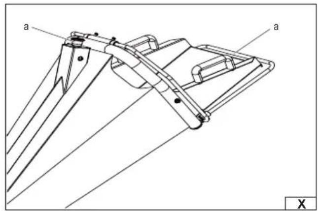
natural_image
Technical line drawing of a mechanical assembly with labeled parts 'a' (no text or symbols beyond labels)
natural_image
Close-up of mechanical components with visible wiring and a central valve (no text or symbols)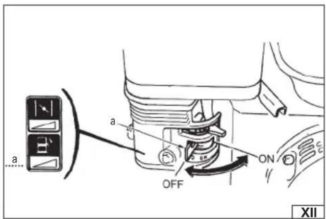
natural_image
Close-up of mechanical components with visible pipes and connectors, no text or symbols present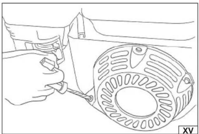
natural_image
Line drawing of a hand adjusting a mechanical component with a circular housing (no text or symbols)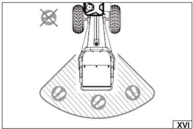
natural_image
Top-down technical diagram of a vehicle with wheels and targeting pad, no text or symbols presentPL EN DE RU UA LT LV CZ SK HU RO ES FR IT NL GR BG PT HR AR
natural_image
Mechanical assembly diagram showing a hand operating a tool with a gear and motor components (no text or labels)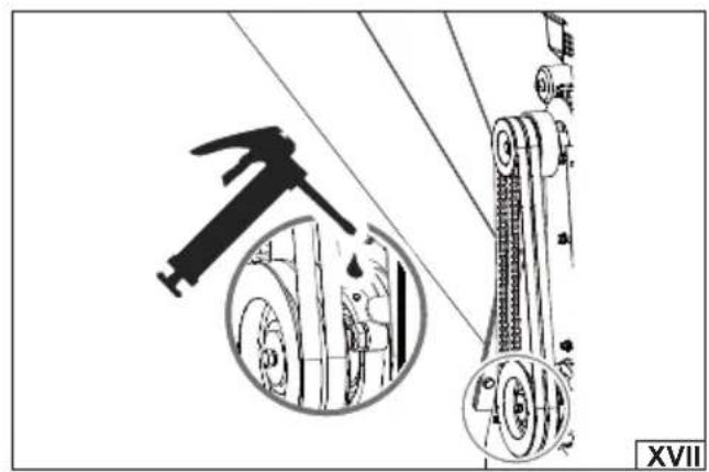
natural_image
Mechanical assembly diagram showing a hammer striking a wheel with an inset close-up of the mechanism (no text or symbols)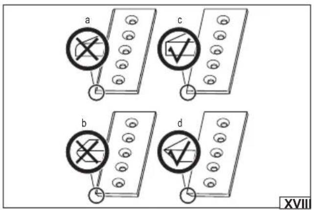
natural_image
Technical line drawing of a dump truck with visible tire tracks and mechanical components (no text or symbols)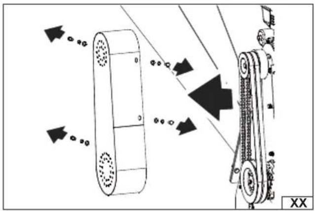
natural_image
Diagram of a mechanical conveyor system with directional arrows indicating motion (no text or symbols)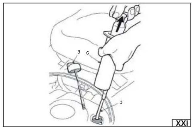
natural_image
Four-panel black-and-white photo showing a robotic arm handling a cylindrical object, with no visible text or symbols.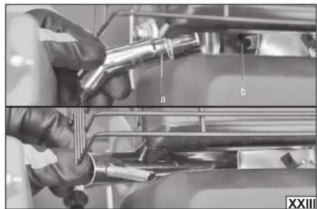
natural_image
Close-up of hands pouring liquid into a container with a small bottle (no visible text or symbols)PL
- inlet hopper
- discharge chute
- engine
- emergency stop
- fuel filler cap
- oil fi ller cover
- air filter cover
- v-belt cover
- support leg
- transport wheel
DE
Read the operating instruction
Use hearing protection and safety goggles
Stay away from bystanders
Keep the safe distance from hot surface
Wear protective shoes
Beware of ejected objects.
Do not smoke while refueling the fuel tank
Zgomotul - puterea L _uA
Turn off the engine before performing servicing or maintenance
PRODUCT CHARACTERISTICS
The petrol shredder is an efficient machine powered by a combustion engine, designed for shredding branches and plant debris. Thanks to its powerful drive, it enables efficient processing of plant material with a diameter of up to 100 mm, which makes it an ideal solution for use in gardens, orchards and garden plots. The correct, reliable and safe operation of the machine depends on proper use, therefore:
Before operating the machine, read the entire manual and keep it.
The supplier is not liable for any damage or injury resulting from use of the machine for purposes other than its intended use, failure to comply with safety regulations and recommendations in this manual. Use of the machine for purposes other than its intended use also results in the loss of the user's rights to warranty and guarantee.
EQUIPMENT
The shredder is supplied complete, but assembly is required before first use.
TECHNICAL DATA
| Parameter Unit of measurement Value | ||
| Catalogue number YT-86155 | ||
| Number of cylinders 1 | ||
| Number of bars 4 | ||
| Fuel type Unleaded petrol E10 | ||
| Type of oil SAE15W-40 | ||
| Engine capacity [cm] | ^3 ] 196 | |
| Maximum power [kW] 4.8 | ||
| Maximum RPM [min] | ^-1 ] | 3600 |
| Cooling | By air | |
| Start-up type | Manual | |
| Fuel tank capacity | [I] | 3.6 |
| Oil tank capacity | [I] | 0.6 |
| Spark plug type | F7RTC | |
| Maximum shredding diameter | [mm] 100 | |
| Mass | [kg] | 100 |
| Noise level | ||
| sound pressure | [dB(A)] | 89.7±3 |
| sound power | [dB(A)] | 104.9 ± 3 |
| Operating/Storage Temperature | [°C] | 5~30 |
GENERAL SAFETY RULES
Getting to know the machine
Before operating the machine, read this manual and the labels on the machine to understand its limitations and potential hazards. The operator must be fully familiar with the controls and their correct operation, including how to stop the machine and disconnect work functions.
Before using the machine, carefully read and understand all instructions and precautions in the operator's manual.
Do not operate the machine without full knowledge of its operation and maintenance procedures, which could result in personal injury or property damage.
If the machine is given to another person, loaned or sold, this manual must be passed on and appropriate safety training must be provided. The operator is responsible for any accidents or injuries that may occur as a result of improper use.
The machine's capabilities should not be exceeded. The machine should be used in accordance with its intended purpose, which will ensure its effective and safe operation.
Personal safety
Never allow children to operate the machine.
Bystanders, children and pets must be kept out of the machine's working area. If people or animals appear in the working area, the machine must be switched off immediately. Children must be under the constant supervision of adults.
Do not operate the machine under the influence of alcohol, drugs or medications that may impair your ability to work safely.
Appropriate protective clothing must be worn. It is advisable to wear long trousers, safety shoes and gloves. It is prohibited to
EN
wear loose clothing, jewellery or shorts that could get caught in moving parts of the machine. Long hair must be secured above the shoulders.
Eyes, face and head must be protected from splashes. Safety glasses or goggles with side shields are required.
Hearing protection should be worn.
During operation, maintain a safe distance from all moving parts of the machine. There is a risk of serious injury in the event of contact with rotating machine parts.
Do not touch machine components that may become hot during operation. Allow the machine to cool before performing maintenance, adjustments or servicing.
Do not work barefoot or in light footwear, such as sandals. It is recommended to use protective footwear that increases grip on slippery surfaces.
Before starting the machine, check its technical condition. The guards must be attached and all screws and nuts properly tightened.
Do not use the machine if it requires repair or is in poor condition. Replace worn or damaged parts before starting work.
Work area
This machine is equipped with a combustion engine. Do not use it near forested, overgrown or dry vegetation areas unless the exhaust system is equipped with a spark arrester that complies with local fire regulations.
Do not start or operate the engine in an enclosed area. Exhaust gas contains carbon monoxide (CO), a colorless, odorless gas that is deadly. The machine may only be used in well-ventilated outdoor areas.
Do not interfere with the engine system to increase its speed above the values permitted by the manufacturer.
It is recommended to carry a Type B fire extinguisher when working in dry conditions to minimise the risk of fire.
Do not operate the machine in conditions of limited visibility or insufficient lighting.
Machine inspection before start-up
Before each use, check the technical condition of the machine, in particular the correct assembly of covers and the tightness of nuts and bolts.
Do not use the machine if it requires repair or is in poor condition. Replace damaged, missing or faulty parts before operating the machine.
Do not operate the machine unless the engine switch stops the engine. Any combustion machine that cannot be turned off with the switch is dangerous and must be repaired.
Regularly check that all keys and adjusting tools have been removed from the machine area before starting it. Tools left behind can be caught in moving parts and cause injuries.
Avoid accidental starting of the machine. Before transporting, maintaining or servicing, make sure that the engine switch is in the OFF position.
If the machine starts to vibrate abnormally during operation, immediately turn off the engine and check the cause. Vibration may be a sign of a serious fault.
Fuel Precautions
WARNING! Fuel is highly flammable and its vapors can explode. Every precaution must be taken to minimize the risk of serious injury.
When fi lling or emptying the fuel tank:
Only use approved fuel containers.
Refuel in a clean, well-ventilated area outdoors.
Before refueling, turn off the engine and wait until it cools down completely.
Do not smoke, use open flames or stay near sparks or high temperatures near fuel.
It is prohibited to refuel the machine in closed rooms.
Store fuel only in approved and properly labelled sealed containers, in a cool, well-ventilated place, away from sources of heat and ignition.
Do not overfill the fuel tank. The fuel level should not exceed 12.5 mm below the bottom of the filler neck to allow room for fuel expansion due to temperature rise.
Any spilled fuel must be wiped up immediately. If fuel is spilled, do not start the machine until the fuel vapors have completely evaporated.
The machine must not be stored with fuel in the tank in an area where fuel vapors could contact ignition sources such as water heaters, furnaces or other high-temperature appliances.
Safety during maintenance and operation
The machine must be positioned so that it cannot accidentally move during maintenance, cleaning, adjustments or the installation of accessories.
Do not overload the machine or force it to work beyond its capabilities.
It is prohibited to interfere with the engine regulator settings or operate the engine at excessive speeds.
Do not place hands or feet near moving parts of the machine.
EN
Avoid contact with hot oil, fuel, exhaust fumes and hot machine parts.
If excessive noise or vibration occurs, turn off the machine immediately and investigate the cause.
Only use accessories and parts recommended by the manufacturer with the machine.
Check and maintain the machine regularly to avoid breakdowns.
Child and pet safety
Children and animals may be interested in the machine and the digging process, which can lead to tragic accidents. Always follow the rules below:
Children and animals should be kept at least 25 m away from the work area and under adult supervision.
Be vigilant and turn off the machine if a child or pet enters the work area.
Never allow children to operate a trencher.
SHREDDER SAFETY AND OPERATION INSTRUCTIONS
WARNING! Before operating the petrol shredder, read and fully understand this instruction manual. Pay special attention to all warnings and precautions.
Improper operation and maintenance of the machine can result in serious injury or death to the operator or bystanders.
Each machine is associated with a specific operational risk. A combustion shredder is characterized by specific hazards that the user should be aware of and consciously avoid. The operator and owner of the device are obliged to be aware of potential hazards and to adhere to safety rules. In order to minimize the risk, appropriate preventive measures should be followed.
The manual should be kept for future reference and review. If the machine is used by someone other than the owner, the operator's manual should be given to them to read. Anyone to whom the shredder is loaned or lent must have access to this manual and be familiar with its contents before starting work. Check that there is a copy of the operator's manual in the container located on the machine's feed chute. Operators must be familiar with the manual before using the machine. It is also recommended that they receive basic training in the safe operation of the machine and remain available for any questions.
Machine Application
The shredder is designed to process branches and plant debris with a maximum diameter specified in the technical data table. Before placing material in the feed hopper, make sure that it is free of stones, metal, glass, plastic and other objects that could damage the machine or pose a risk to the user. Placing the wrong materials in the feed hopper can damage the machine and create a risk of fragments being thrown back towards the operator. Never exceed the maximum shredding diameter or place too much material in the feed hopper to avoid material blocking or being thrown back towards the operator, overloading or damaging the machine.
Before starting work
Carefully inspect the work area, ensuring it is clean and free from any debris to prevent tripping. The machine should be used on a fi rm, level surface.
Before starting the shredder, make sure that the feed chute and the cutting blade housing are empty and free from contamination, check the oil level, the tightness of all nuts and bolts and the tire pressure.
Rules for safe operation
Recommended fuel: E10 unleaded petrol with a minimum octane rating of 95.
You should use fuel and oil free of any impurities, and designed for four-stroke engines. It is recommended to use high-quality products. This will extend the life of the engine.
Keep bystanders and animals at least 25 meters away from the work area. If people approach the machine, stop it immediately.
Never place any part of your body in a place where it could be endangered by the movement of the machine during assembly, installation, operation, maintenance, repair or relocation.
Never put hands, feet or any part of the body in the feed chute, discharge chute or near moving parts of the machine while it is operating.
The discharge area should be free of people, animals, buildings, glass and other objects that could obstruct the free discharge of material, causing injury or damage. Wind can change the direction of discharge, so care should be taken.
If it is necessary to push the material in the feed hopper, use the pusher supplied with the machine (if the machine is equipped with one) or another pusher that provides a safe distance between the hand and the cutting elements. Do not use your hands or any other parts of your body for this purpose, to avoid the risk of contact with the cutting elements.
Keep your face and body away from the feed chute and discharge chute to avoid injury from rebounding material or debris.
Never reach into the feed chute with your hands beyond the rubber cover while the machine is running.
Before starting work, make sure that the shredder is properly assembled.
Do not use the machine in damp or wet environments, during precipitation or where there is a risk of lightning.
Do not modify the machine in any way or use substitute blades other than the originals.
After replacing the blades, make sure they rotate freely and without obstruction before restarting the shredder.
Work must be undertaken wearing appropriate work clothes, gloves, full footwear, safety goggles and hearing protection.
EN
The fuel supply system should be checked periodically. If you notice any leaks, take the machine to an authorized service center for repairs.
Regularly check the engine oil level – using the machine with too low an oil level or no oil at all may result in damage or even fire.
Avoid contact with hot fuel, oil, exhaust fumes and hot machine surfaces. Do not touch the engine or muffler, as these parts become very hot during operation and remain hot for some time after operation. Allow the machine to cool before servicing or adjusting.
Never use the machine without the inlet chute and discharge chute properly installed.
The engine ventilation openings must not be covered – they must be unobstructed and clean at all times.
Do not operate the machine in enclosed spaces without adequate ventilation – exhaust fumes contain harmful substances that should not be inhaled.
The machine must not be used without properly installed protective guards and if the machine's safety systems are not working properly. Defective safety systems increase the risk of accidents, therefore, before each start-up, make sure that all guards are properly installed and that the safety mechanisms are working properly.
If you notice any suspicious symptoms, such as increased vibration, noise or an unusual smell, immediately turn off the machine, allow it to cool, disconnect the spark plug wire, remove the hopper and inspect the cutting unit for damage.
Only original spare parts should be used for repairs and maintenance.
Before starting work, wait until the engine reaches rated speed.
If you leave the machine unattended, turn it off and wait until the cutting element comes to a complete stop.
Make sure that the ejection opening is not clogged at all times.
Do not lift, tilt or carry the machine with the engine running.
Stop the machine engine and make sure all moving parts have stopped:
-every time you need to step away from the machine,
-before cleaning, checking, replacing accessories or repairing the machine,
-after being hit by a foreign object,
-before transporting to and from the workplace,
-if the machine begins to vibrate excessively.
NOTE! After the engine is turned off, moving parts may continue to rotate for some time. Wait until the moving parts of the machine have stopped.
Clearing blockages
Do not allow processed material to accumulate in the discharge area as this may impair proper machine operation and cause material to be thrown from the feed hopper.
Never clear a blockage in the hopper or discharge chute while the engine is running. If a blockage occurs, immediately turn off the engine, wait for the cutting unit to come to a complete stop and the machine to cool, and then disconnect the spark plug wire before attempting to clear the blockage. After clearing the blockage, inspect the machine for damage and loose parts that require repair or replacement.
If it is necessary to leave the work area or remove processed material, always turn the engine off, turn the switch to the OFF position, wait for all moving parts to stop and the machine to cool, and then disconnect the spark plug wire to prevent accidental starting.
Before opening the cutting unit housing, make sure all moving parts have completely stopped, the engine has cooled down and the spark plug wire has been disconnected.
Waste management
Used consumables, packaging and tools should be recycled in accordance with applicable environmental protection regulations.
Waste should be taken to a local recycling point in a manner consistent with the principles of industrial waste disposal.
PRODUCT ASSEMBLY
Preparation for assembly
The product should be unpacked from the packaging and all packaging elements should be removed. It is recommended to keep the packaging, which may be useful during transport or storage of the product. Check whether none of the product parts have been damaged during transport, any observed damage, e.g. cracks or deformations, disqualify the product from further use until they are repaired or the damaged parts are replaced.
It is recommended to place the machine on a flat, hard and clean surface.
Personal protective equipment such as protective gloves, eye protection and protective clothing should be worn during installation.
Machine assembly
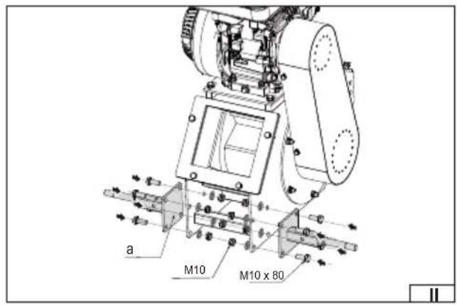
To assemble the machine, mount it as shown in the illustration:
(II) – Fasten the wheel axle (a) to the main frame on both sides of the machine using M10×80 mm hexagonal bolts, flat washers and M10 self-locking nuts.
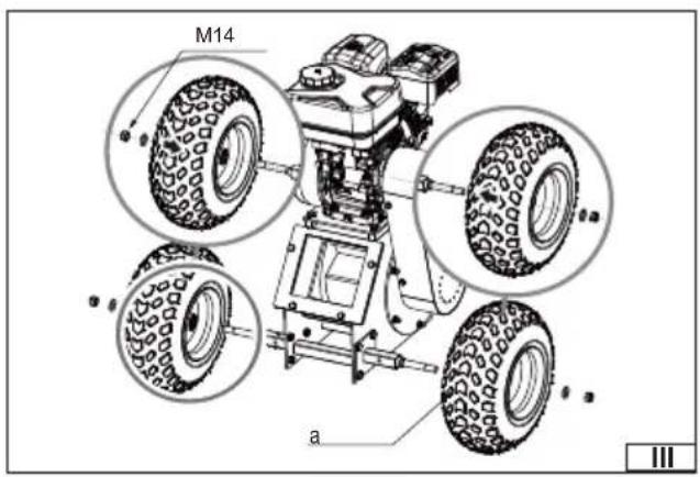
(III) - Attach the wheels (a) to the axle using M14 nuts.
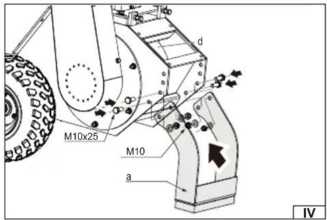
(IV) - Mount the support leg (a) to the main machine frame using M10×25 mm hexagonal bolts, flat washers and M10 nuts.
EN
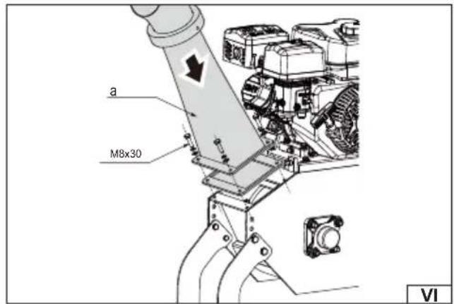
(V) – Mount the discharge chute (a) to the main frame of the machine using M8×30 mm hexagonal bolts, M8 self-locking nuts and fl at washers.
(VI) – Attach the hopper (a) to the main frame of the machine using M8×25 mm hexagonal bolts, M8 self-locking nuts and flat washers.
PREPARING FOR WORK
Preparing the workplace
Before starting work, make sure that the ground is stable, even and dry, and that the machine is set up in a way that ensures its full stability. It is not recommended to set up the machine and work on an inclined surface. The work area should be free of foreign objects that could cause accidents. Bystanders and animals must be at a safe distance of at least 25 m. Before starting work, you should also take into account the weather conditions - strong winds can cause uncontrolled movement of waste and increase the risk of hazards.
Preparing the machine for work
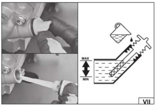
NOTE! The engine may only have a small amount of oil in it from the factory to protect it during transport and storage. Before first start-up, check the engine oil level and then top up to the required level. The oil level should be checked regularly and topped up as necessary. Starting the machine without oil or with too little oil in the engine gearbox can lead to irreversible damage.
You should prepare oil intended for four-stroke engines with a viscosity class of SAE 15W-40.
Before topping up the oil, place the machine on a flat surface, then unscrew the oil tank cover (VII) and wipe the oil dipstick dry. Fill the tank with oil. When filling, it is recommended to use a funnel or a filler neck to avoid spilling the oil. If oil spills, wipe off any residue before starting the engine. Check that the oil level is correct. To do this, insert the dipstick into the filler hole and screw on the tank cover. Then unscrew it and check the oil level on the dipstick. The oil level should be between the maximum and minimum levels on the dipstick. After making sure that the oil level is correct, close the filler hole with the cap.
Note! The oil level must be checked each time before starting work.
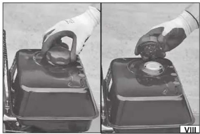
After adding oil, add fuel. The fuel is unleaded petrol with an octane rating of at least 95. To add fuel, unscrew the fuel tank cap (VIII) and pour fuel into the tank. When filling the fuel, it is recommended to use a filler or funnel to reduce the risk of fuel spilling. If fuel spills, wipe off any remaining fuel thoroughly. Wait until the vapors have completely evaporated and start the engine in a different place than where fuel was filled. After filling the fuel, close the fuel tank filler opening with the cap.
The machine is equipped with pneumatic wheels. The recommended tire pressure is 20 PSI / 1.4 BAR. The tires must be inflated before starting work. Do not exceed the recommended tire pressure. Check the tire pressure before starting work. Always inflate the tires to the same pressure.
Warning! Incorrect or uneven tire pressure can lead to dangerous situations, such as the machine tipping over on its side, which could result in serious injury or even death.
Adjusting the throwing angle (IX)
The deflector located at the end of the discharge chute is used to adjust the angle of discharge of the shredded material, allowing its direction to be adjusted to the working conditions.
Before starting work, the throwing angle must be adjusted. To do this, loosen the deflector lever by turning it counterclockwise, set the appropriate angle, and then tighten the lever by turning it clockwise.
Component check
Before first use, carry out a thorough inspection of the machine to ensure that all components are properly installed and free from damage.
PRODUCT SERVICE
Emergency stop switch (X)
The machine is equipped with two emergency stops, which are used to stop the machine in an emergency. Pressing one of the switches (a) stops the engine. Both emergency stops must be lifted up for the engine to run.
For safety reasons, it is recommended to regularly check the correct operation of emergency switches.
Caution! After the engine stops, the cutting element may continue to rotate for some time. Wait until the cutting element stops by itself. Do not bring any parts of the body or other objects close to the rotating cutting element.
Starting the combustion engine
WARNING! Do not run the engine in a closed or poorly ventilated area because the exhaust fumes contain carbon monoxide, an odorless, toxic gas that can cause poisoning, unconsciousness, or even death. When running the engine, provide adequate ventilation to prevent the accumulation of exhaust fumes.
NOTE! Before each start of the engine, make sure that the engine oil level is correct.
Make sure that the material to be shredded is not in the feed hopper.
EN
Make sure both emergency stop switches are in the up position. Both emergency stop switches must be in the up position for the engine to run.
Turn the engine switch (XI) on the engine to the ON position to turn on the engine ignition system. The switch must be in the ON position for the engine to run.
As shown in illustration (XII), open the fuel valve by moving the fuel valve lever (a) to the ON position.
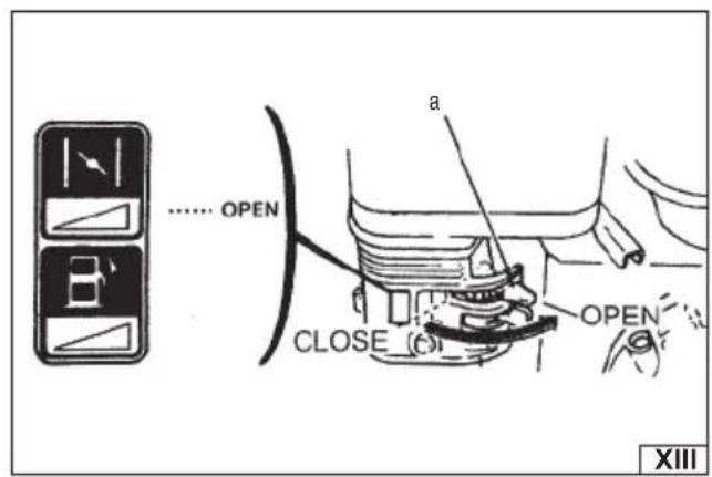
As shown in illustration (XIII), to start a cold engine, close the throttle valve by moving the choke lever (a) to the CLOSE position, and to start a warm engine, open the throttle valve by moving the choke lever (a) to the OPEN position.
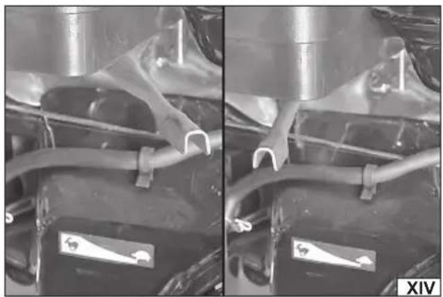
Move the throttle lever (XIV) slightly towards the high speed position, marked with the hare symbol.
Pull the starter cord handle (XV) several times smoothly until you feel resistance caused by engine compression, then pull with a vigorous, decisive movement. After a few pulls, the engine should start.
After starting the engine, do not release the starter rope handle from your hand, but move it to the lower position.
As the engine warms up, gradually move the choke lever towards the OPEN position. After each change of the choke lever position, wait until the engine is running smoothly. The speed of the choke lever return depends on the weather conditions in which the engine is started. The lower the ambient temperature, the slower the return must be.
After the engine has warmed up, move the throttle lever fully to the high speed position, marked with the hare symbol, to increase engine speed. Wait until the engine reaches rated speed before starting work.
Stopping the engine
To stop the engine in an emergency, press the emergency stop switch down.
Under normal circumstances, the following steps should be followed:
Move the throttle lever (XIV) to the low speed position, marked with the turtle symbol.
Allow the engine to idle for one to two minutes.
Turn the engine switch (XI) to the OFF position.
As shown in illustration (XII), close the fuel valve by moving the fuel valve lever (a) to the OFF position.
NOTE! Stopping the engine suddenly at high RPM and under heavy load is not recommended. This can damage the engine.
CAUTION! Do not close the throttle to stop the engine. This may cause backfire or engine damage.
CAUTION! The blades may continue to rotate for some time after the engine has stopped. Keep hands and feet away from the rotating cutting element. Before performing maintenance, wait until all rotating parts have stopped and the engine has cooled down completely, then disconnect the spark plug wire.
Refueling
Fuel is highly flammable! Observe all safety precautions for handling fuel. Do not fill the fuel tank while the machine is running. Do not refuel near an open flame. Do not smoke in the refueling area. Do not spill fuel. If fuel is spilled, thoroughly dry the spilled fuel before starting the machine. Tighten the fuel filler cap tightly and securely. Store fuel in tightly closed, approved containers away from heat sources and in a place inaccessible to children.
Stop the engine according to the procedure described above.
Wait for the engine to cool down.
The fuel is unleaded petrol with an octane rating of at least 95. To refuel, unscrew the fuel tank cap (VIII) and pour fuel into the tank. When filling the fuel, it is recommended to use a filler or funnel to reduce the risk of fuel spilling. If fuel spills, wipe off any remaining fuel thoroughly. Wait until the vapors have completely dissipated and start the engine in a different place than where the fuel was filled. After filling the fuel, close the fuel tank filler opening with the cap.
Restart the engine according to the procedure in section „Starting the combustion engine”.
Working with a shredder
NOTE! Make sure the machine is stable and level to avoid excessive vibration.
WARNING! Do not use the machine on concrete or other hard surfaces.
NOTE! The engine is equipped with an oil level sensor and will not start if the oil level is too low. It may also stop if the machine is operating on a steep slope. Operation on uneven terrain and slopes is not recommended.
WARNING! Do not open the cutting unit cover until the engine and cutting unit have completely stopped and the spark plug wire has been disconnected.
WARNING! Never use the machine without the inlet chute and discharge chute properly installed.
After the engine has warmed up, move the throttle lever fully to the high position to increase engine speed.
Illustration (XVI) shows the shredder's operating zone, which includes the area in front of the feed hopper - this is the area where the operator can safely feed material. It is forbidden to stand on the sides or behind the machine during its operation to avoid dangerous situations.
The shredder can process various types of dry and green organic materials, such as branches, stems, vines, leaves, roots and plant residues. The maximum diameter of the shredded branches is 100 mm, but this may vary depending on the type and hardness of the wood. Rotating the branches while feeding into the machine improves the shredding efficiency.
Before placing the material to be shredded into the feed hopper, wait until the engine has reached its rated speed.
Branches should be fed with the cut end forward, leaving leaves and branches at the end. This makes it easier to guide the ma-
EN
terial through the feed chute and prevents it from turning and bouncing off into smaller pieces. In the case of side branches, they may need to be trimmed first so that the branch is better taken up by the cutting mechanism.
It is recommended to use freshly cut branches, as dry wood is harder, more brittle and dulls knives more quickly.
When working, it is a good idea to have a wooden stick about 2.5 cm in diameter and 60 cm long at hand, which can be used to push thin, leafy and fine materials and to keep the hopper clear.
Do not force the material. If the machine is not shredding the branches properly, it may mean that:
-the blades need sharpening or replacement,
-the gap between the blades and the pressure plate requires adjustment.
Do not overload the machine by feeding too much material at one time. If the engine speed begins to drop, immediately stop feeding material and wait until the engine speed returns to rated speed before resuming operation.
The shredder may become blocked by soft, wet or fibrous materials. To prevent this, it is recommended to alternate feeding soft materials with branches, which will clean the cutting mechanism.
If the machine stops due to overload or material blockage:
-Switch off the engine immediately using one of the emergency stops and wait until the cutting disc has come to a complete stop.
-Wait for the engine to cool, turn the engine switch to the OFF position and disconnect the spark plug wire.
-Open the case, remove the blocked material, and then close the case.
-Connect the spark plug wire, raise the emergency stop switch, then restart the machine and resume work.
If fibrous material becomes wound around the rotor shaft, it must be removed immediately before it enters the bearings and causes damage.
If shredded material begins to build up, move the machine away from the pile to prevent it from flowing back into the discharge chute.
Do not place the discharge chute deflector in a vertical position as this may restrict airflow and cause blockages.
When work is completed, turn the engine off according to the stopping procedure.
Wait until the machine has come to a complete stop and the engine has cooled down.
Once cool, disconnect the spark plug wire and then proceed with machine maintenance.
What to do in the event of striking a foreign body or excessive vibration
If the machine's cutting element strikes a foreign object or the machine starts making unusual noises or vibrates excessively, immediately turn off the engine using one of the emergency stops and wait until the cutting element has come to a complete stop.
Turn the engine switch to the OFF position, wait for the machine to cool down completely, and then disconnect the spark plug wire to prevent accidental starting. Then:
-check the machine for damage.
-repair or replace damaged components.
-check that all parts are properly attached and tightened to ensure continued safe operation.
MAINTENANCE
Warning! Before performing maintenance, turn off the machine's engine, wait until the blade stops and the machine has cooled down completely, and then disconnect the spark plug wire. When performing maintenance, wear personal protective equipment such as protective gloves, eye protection, and protective clothing.
During the warranty period, the user may not disassemble the device or replace any other components or parts than those listed below, as this will void the warranty. Any irregularities observed during inspection or during operation are a signal to carry out repairs at a service point.
General maintenance activities
After each job, check the general technical condition of the machine, paying attention to loose screws, misalignment or blockage of moving parts, as well as cracks and other damage that may affect safe use. In addition, after each transport and after every 25 hours of operation, make sure that all screw connections are properly tightened.
After finishing work, the shredder should be cleaned by removing any dirt using a soft brush, vacuum cleaner or compressed air. The housing, ventilation slots, switches, handles and covers can be cleaned with an air jet with a pressure not exceeding 0.3 MPa, a brush or a dry cloth, avoiding the use of chemicals and cleaning fluids. The machine must not be washed with water or immersed in water. Tools and handles should be wiped with a dry, clean cloth. After cleaning all elements, the moving parts should be lubricated with a high-quality light machine oil.
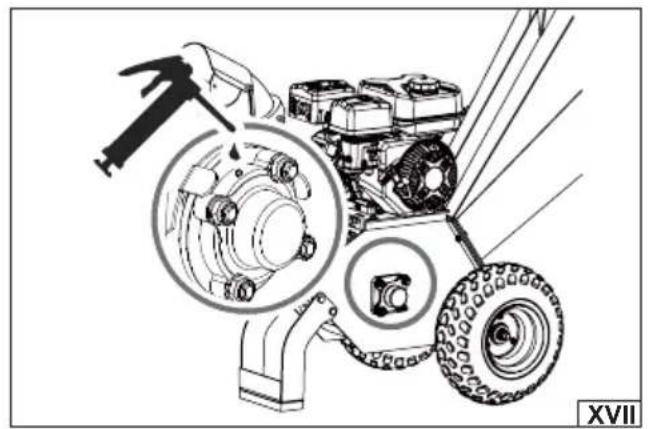
Lubrication of the cutting element shaft bearings (XVII)
The shredder is equipped with two bearings – one is located outside the machine housing and the other on the opposite side, under the V-belt cover. The bearings are factory-lubricated, but it is recommended to lubricate them after a few hours of operation. In order to ensure proper operation and extend the life of the cutting element, the bearings of the cutting element shaft should be regularly lubricated. Lubrication is carried out through grease nipples located on both sides of the shaft.
To do this, clean the grease nipples from dirt to prevent contamination from entering the lubrication system. Open the protective caps.
EN
Using a suitable grease gun, inject NLGI grade 2 industrial grease until grease appears at the seals.
After lubrication, remove excess grease and protect the grease nipples with protective caps.
Regular lubrication reduces friction, prevents premature wear of bearings and ensures smooth operation of the cutting element.
Cutting element maintenance
After finishing work, check the degree of wear and damage to the cutting blades. If excessive wear or damage to the blades is observed, replace them with new ones free from defects. The blades should also be replaced if a decrease in work efficiency is observed. Worn cutting blades can overload the engine and lead to its damage, so they should be replaced every two years or every 50 hours of operation. The cutting blades should always be replaced with original ones, identical to those supplied with the machine. Only the use of original spare parts allows you to maintain the safety of the product. The replacement of blades should be carried out by an experienced user. In case of doubt, contact an authorized service center of the manufacturer.
CAUTION! Before starting to replace the cutting elements, turn off the machine's engine, wait until the blade stops and the machine cools down, and then disconnect the spark plug wire. The shredder blades are very sharp. When replacing them, be very careful to avoid cuts.
WARNING! Use caution and wear protective gloves when handling knives to reduce the risk of cuts.
Knife and pressure plate control (XVIII)
Regularly checking the sharpness of the knives and the pressure plate ensures optimum performance of the shredder. Using blunt knives or a worn, rounded pressure plate reduces the shredding efficiency, causes excessive vibrations, which can damage the machine or reduce the work efficiency.
A worn pressure plate (a) and blunt knives (b) reduce shredding efficiency, causing increased vibration and the risk of material jamming during operation and damaging the machine.
A well-sharpened pressure plate (c) and sharp cutting knives (d) enable efficient operation of the shredder.
Replacing cutting knives (XIX)
The shredder is equipped with two cutting knives mounted on the cutting disc. When the knives become blunt or damaged, the machine loses the ability to automatically feed the material, and the shredded material may come out in long strips. To replace the knives, follow these steps:
Dismantle the hopper.
Turn the cutting disc until the blade is visible from the feed chute side.
Unscrew the screws securing the knife.
Remove dull or damaged blades and inspect the mounting surface on the cutting disc.
The surface on which the knives are mounted must be clean and even.
Mount new or sharpened knives flat on the cutting disc, with the blade facing up.
The gap between the blades and the pressure plate should be approximately 1 mm at the closest point to the rotor shaft and 3 mm at the furthest point. The design of the blades allows for a small movement of the cutting disc when cutting wood.
Make sure all lock nuts are properly tightened. After assembly, turn the cutting disc with a long wooden stick to check that it turns freely.
CAUTION! If the surface of the cutting disc is not thoroughly cleaned or the blades are not properly secured, there is a risk of the blades breaking when tightening the screws.
Adjusting the V-belt tension
Before starting to use the shredder, check the belt tension. The belt may become loose after 1-2 hours of use, so it is necessary to re-check and adjust if necessary. Incorrect tension can cause slippage and accelerated belt wear. For best performance, it is recommended to check the belt tension every 20 hours of use.
To tension the V-belt, unscrew all mounting screws and then remove the V-belt cover (XX).
Loosen the four screws securing the engine base, which will allow the engine to be moved.
Loosen the lock nut on the tensioning bolt, which also serves to align the axis of the pulleys.
Turn the tensioning screw clockwise to increase the V-belt tension, or counterclockwise to decrease it.
Check the V-belt tension – Belt deflection should be less than 10 mm with a pressure of 4 kg at its centre.
If necessary, correct their setting by adjusting the position of the engine relative to the base.
Tighten the lock nut and engine base mounting screws.
Install the V-belt cover with the mounting screws.
If you notice any damage to the V-belt or a decrease in the machine's efficiency, replace the belt with a new one, free from defects.
To do this, loosen the tensioning bolt and the four bolts securing the engine base, remove the worn belt, install a new V-belt, and then adjust the tension according to the above procedure. It is possible to use the YATO YT-861913 V-belt.
Checking the oil level
Unscrew the filler cap and remove the oil level gauge (VII).
Clean and dry the indicator with a clean cloth.
Insert the dipstick into the filler but do not turn it. Then remove it and observe the indicated oil level.
EN
If the level indicated is too low, top up the oil to the upper level of the dipstick (dashed area).
Screw the dipstick into the oil filler neck.
Engine oil change
The engine oil should be changed after the first 2 to 5 hours of operation. Any subsequent oil change should be performed every 25 hours of operation.
Be careful when changing the oil. The oil is hot right after the engine is stopped and can cause burns. The used oil should be extracted using a suction device designed for this purpose, in accordance with the suction device manufacturer's recommendations.
As shown in the illustration (XXI), unscrew the oil filler cap (a), insert the tube (b) of the suction device (c) directly into the oil filler hole, and then suck out all the engine oil, remembering that the operation must be repeated several times until all the oil has been removed. After the suction operation is finished, wipe off any remaining oil.
Top up the oil according to the procedure described in section: "Preparing for operation".
NOTE! Used engine oil must be disposed of in accordance with local regulations. It is prohibited to pour engine oil into the sewage system.
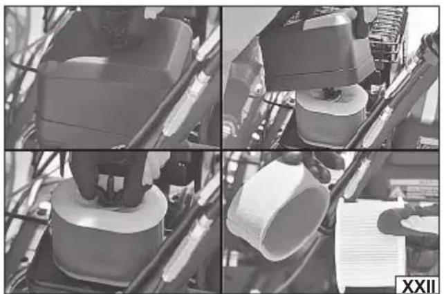
Air fi Iter maintenance (XXII) - every 40 hours of operation
WARNING! Do not use the device without a properly installed air filter or with a damaged air filter. Otherwise, the combustion engine may suck in impurities that would normally be retained by the filter. Impurities can lead to engine malfunctions or even damage.
Completely unscrew the knob or knobs securing the filter housing, then remove the filter cover. Remove the filter from the base. The air filter consists of two elements – paper and sponge. Carefully check each filter element for holes, tears and damage. If any filter element is damaged or cannot be cleaned during maintenance, it must be replaced with a new one, free from defects. It is possible to use the YATO YT-861933 air fi Iter.
Clean the paper element with a compressed air jet (pressure no higher than 0.2 MPa), blowing out the dirt from the inside or sucking out the dirt from the outside using a narrow vacuum cleaner brush. Due to the delicate structure of the paper filter, gentle cleaning is recommended. The paper element should not be soaked in water or any other liquid. Do not brush to avoid rubbing dirt into the filter structure.
Clean the sponge element in warm water with dishwashing liquid, rinse thoroughly and leave to dry completely. Soak the dried filter sponge in clean engine oil and squeeze out, but so that the filter remains moist.
Use a cloth slightly dampened with water to clean dirt from the inside of the filter base and the filter cover. Be careful not to allow dust or dirt to enter the line leading to the carburettor.
Place the sponge element on the paper filter element. Install the filter in place and close the filter cover. Make sure the filter cover is tightly closed and the filter housing mounting knob is properly tightened.
Spark plug maintenance (XXIII) - every 100 hours of operation
Disconnect the wire (a) from the spark plug (b). Unscrew the spark plug with a spark plug wrench. Clean the electrodes from carbon deposits with a wire brush. Check the distance between the electrodes, it should be between 0.7 mm and 0.8 mm.
If you find burnt electrodes or a cracked ceramic cover, replace the spark plug with a new one. Screw in the spark plug. Connect the wire to the spark plug.
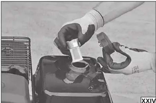
Fuel filler filter maintenance
Remove the fuel filler cap (VIII). Pull out the fuel filler filter (XXIV). Clean the fuel filler fi lter with white spirit. Dry with a soft, clean cloth. Install the filter in the filler opening. Install the fuel filler cap.
Attention! The filter walls are made of a delicate mesh. Care should be taken during maintenance to avoid damaging them. If the filter is damaged, it must be replaced with a new one without damage before resuming operation.
PRODUCT STORAGE AND TRANSPORT
If the machine will not be used for longer than 30 days, follow the steps below to properly prepare it for storage.
Note! Always empty the fuel tank before storing or transporting.
Completely drain the fuel tank, as fuel containing ethanol can lose its properties after just 30 days. Used fuel can contain resin deposits that can clog the carburetor and restrict fuel flow.
Start the engine and run it until it stops by itself. This will ensure that all fuel is drained from the carburettor. Running the engine until it is completely empty helps prevent carbon build-up inside the carburettor and possible engine damage.
While the engine is still warm, drain the engine oil. Then fill the system with fresh oil of the specification recommended in the technical data table.
Use clean cloths to clean the outside of the machine and to remove dirt from the vents to keep them clear. Keep the vents clear during storage. Do not cover the vents.
Caution! Do not use strong detergents or petroleum-based cleaners to clean plastic parts, as the chemicals may damage the plastic parts.
Clean according to instructions.
EN
Store in dark, dry, frost-free and well-ventilated areas. The storage location should be protected from access by children. The product should be stored at a temperature between 5 and 30 degrees Celsius. It is recommended to store the product in the factory packaging or in another packaging that protects against dust. Store the product in a horizontal position.
During transport, the machine must be protected from impacts and strong vibrations that can damage its components. The machine must be transported in a horizontal position and properly secured to prevent it from moving, slipping or tipping over.
When transporting short distances, the machine should be moved on its wheels, tilting it slightly backwards using the transport handles. Take special care to prevent the machine from tipping over, as this could damage it or create a dangerous situation.
After each transport, check that the mounting screws are properly tightened.
PROBLEM SOLVING
Below are typical faults and possible solutions. If in any doubt, stop using the product and contact an authorized service center for the manufacturer.
| Problem Cause Solution | ||
| Engine won't start 1. Spark plug wire disconnected | 2. No fuel or old fuel3. Engine stop switch and/or fuel valve not in ON position4. Choke lever not in CLOSE position5. Blocked fuel line6. Dirty spark plug7. Too much fuel in cylinder (engine fl ooding) 8. Emergency stop switch pressed | 1. Connect the spark plug wire2. Fill the tank with clean, fresh gasoline3. Turn the engine stop switch and fuel valve to the ON position4. Set the choke lever to the CLOSE position - closed for cold starts5. Clean the fuel line6. Clean, adjust the gap or replace the spark plug7. Wait a few minutes before trying to start again, do not pump fuel8. Lift the emergency stop switch up |
| Engine runs unevenly 1. Loose spark plug cable | 2. Operating with the choke lever in the CLOSE position3. Blocked fuel line or old fuel4. Clogged fuel tank vent5. Water or dirt in the fuel system6. Dirty air fi lter7. Incorrect carburetor adjustment | 1. Connect and tighten the spark plug wire2. Move the choke lever to the OPEN position3. Clean the fuel line and fi ll the tank with fresh fuel4. Clean the vent hole5. Drain the fuel tank and fi ll with clean fuel6. Clean or replace the air fi lter7. Consult the manufacturer's service |
| The engine is overheating 1. Low oil level | 2. Dirty air fi lter3. Restricted air flow4. Incorrectly adjusted carburetor | 1. Fill oil to proper level2. Clean air fi lter3. Clean and ensure free air flow4. Consult engine manual |
| Shredding is too slow, the cutting disc stops or the material is not ejected | 1. Engine speed is too low, causing belt slippage2. Drive belt is loose or damaged3. Blades are dull or damaged4. Cutting disc is blocked by material 5. Discharge chute is clogged | 1. Increase engine speed2. Tighten or replace drive belt3. Sharpen or replace blades4. Remove accumulated material and turn the cutting disc with a wooden stick to check that it rotates freely5. Consult manufacturer's service |
| Drive belt frays or falls off pulley | 1. The pulley groove may be damaged2. The drive belt may be stretched3. The pulleys may be misaligned | 1. Check the condition of the drive belt and smooth out any damage on the pulley2. Replace the drive belt3. Correct the alignment of the pulleys |
| While shredding branches, the machine vibrates excessively and produces unusual noises | 1. The knives are blunt or damaged2. The knives are not properly mounted on the cutting disc3. Too large a gap between the knives and the pressure plate4. Excessive load on the cutting element | 1. Sharpen or replace the blades2. Loosen the blade mounting screws, adjust the blades correctly and tighten the screws3. Adjust the gap 4. Wait for the machine to clear excess material before adding more branches |
| The knives hit the pressure plate Incorrectly set gap between knives and pressure plate Adjust the gap | ||
| The machine's wheels pull to the left or right during transport | Tire pressure too low Pump up the tires | |
DE
PRODUKTMERKMALE
PRODUKTA RAKSTUROJUMS
ASSEMBLAGE DU PRODUIT
WERKING VAN HET PRODUCT
DEKLARACJA ZGODNOŚCI | DECLARATION OF CONFORMITY DECLARATIE DE CONFORMITATE
0325/YT-86155/EC/2025
We declare and guarantee with full responsibility that the following products:
meet requirements of the following European Standards / Technical Specifications:
and fulfill requirements of the following European Directives:
Serial number: concern all serials numbers of item(s) mentioned in this declaration
Measured sound power level on an equipment representative for this type:
Guaranteed sound power level for this equipment: