YT-73938 - Auto welding mask Yato - Free user manual and instructions
Find the device manual for free YT-73938 Yato in PDF.


| Product type | Automatic welding helmet |
| Brand and model | Yato YT-73938 |
| PPE category | Personal protective equipment category II (eye and face protection) |
| Standards | EN 175:1997, EN ISO 16321-2:2021, PPE Regulation 2016/425/EU |
| Hood material | Polyamide |
| Headband material | PE with PE foam lining |
| Protective lens material | Polycarbonate |
| Dimensions (estimated) | Approximately 30 x 20 x 15 cm |
| Weight (estimated) | Approximately 500 g |
| Power supply | 2 CR2450 batteries (included) |
| Filter response time | 1/25,000 second |
| Darkening level range | 4 to 14 (CUT mode: 4-8, WELD mode: 9-14) |
| Operating modes | Welding (WELD), Cutting (CUT), Grinding (GRIND - permanent light state) |
| Settings | Sensitivity (0-9), delay (0-9), manual/automatic darkening, 10 setting memory, side windows |
| Battery indicator | 4-level display on control panel |
| Working temperature range | -5°C to +55°C |
| Care and cleaning | Soft damp cloth; no solvents; do not immerse filter |
| Storage | In original packaging, away from light, dry, ventilated, -20°C to +70°C |
| Safety | Particle protection at 120 m/s (hood) and 45 m/s (rear lens); do not use without lens; stop if malfunction |
| Available spare parts | Front lens YT-73939, CR2450 batteries, rear and side protective lenses |
| Repairability | Replace only with original parts; do not modify; contact support after impact |
Frequently Asked Questions - YT-73938 Yato
User questions about YT-73938 Yato
0 question about this device. Answer the ones you know or ask your own.
Ask a new question about this device
Download the instructions for your Auto welding mask in PDF format for free! Find your manual YT-73938 - Yato and take your electronic device back in hand. On this page are published all the documents necessary for the use of your device. YT-73938 by Yato.
USER MANUAL YT-73938 Yato
CE
PL EN DE RU UA LT LV CZ SK HU RO ES FR IT NL GR BG PT HR AR
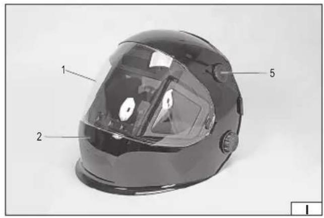

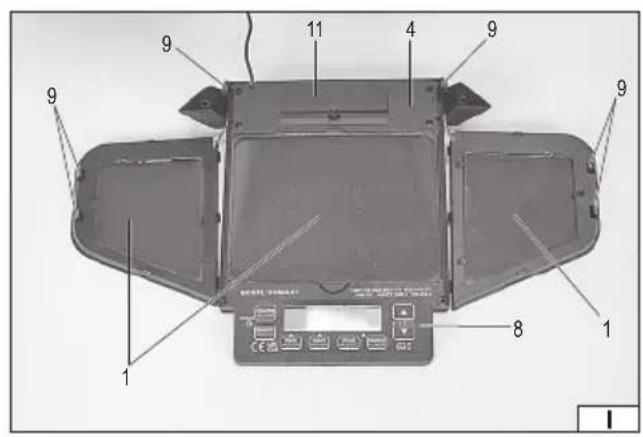
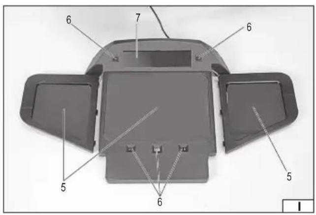
- protective glass panel
- welding shield
- headband adjustment knob
- welding protection filter
- operating mode switch
- filter visor
- filter sensor
- solar cells
- fi Iter control panel
- filter holder
- headband strap
- battery compartment cover
DE
This symbol indicates that waste electrical and electronic equipment (including batteries and storage cells) cannot be disposed of with other types of waste. Waste equipment should be collected and handed over separately to a collection point for recycling and recovery, in order to reduce the amount of waste and the use of natural resources. Uncontrolled release of hazardous components contained in electrical and electronic equipment may pose a risk to human health and have adverse effects for the environment. The household plays an important role in contributing to reuse and recovery, including recycling of waste equipment. For more information about the appropriate recycling methods, contact your local authority or retailer.
Producent: Wenzhou Xidin Electronics Technology Co., Ltd., No. 18 Nanwei 1st Road Ouhai Economic Development Zone, Wenzhou City, Zhejiang, Chiny
Importer: TOYA SĄ, ul. Sołtysowicka 13/15, 51-168 Wrocław, Polska
The content of the manual as per EN 175:1997; EN ISO 16321-2:2021/PPE Regulations 2016/425/EU
Manufacturer: TOYA SA, ul. Sołtysowicka 13/15, 51-168 Wrocław, Poland
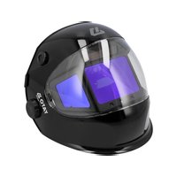
Product description: The welding helmet with an automatic welding protection filter with manual adjustment is a Category II eye and face protection equipment designed for individual protection of eyes and face against mechanical and light hazards. The helmet has increased mechanical resistance. It does not protect against liquid drops and splashes, coarse and fine dust particles, gas and arcs caused by electrical short-circuits. The shield is made of PA66 polyamide and fitted with a headband allowing the helmet to be worn on the head made of PE and helmet lining made of HD-PE foam. The welding protection filter protects the eyes against radiation generated by electric arc during welding and has a shade level adjustment in the range of 4-14. The filter is protected by a polycarbonate glass panel. Persons allergic to these materials may develop an allergic reaction.
Shelf life: The product does not have a specific lifetime. Pay attention to wear and damage of the helmet components. Replace in accordance with the instructions in the manual.
Explanation of filter designations: YATO – manufacturer's designation; 16321 – number of European standard for eye and face protection for professional use; W3/4-8/9-14 – marking of welding filter with manual adjustment of protection level: W3 – bright condition no.; 4 – brightest dark state no.; 14 – darkest dark state no.; W3/7<14 – marking of welding filter with automatic adjustment of degree of protection; W3 – bright state no.; 7 – brightest dark state no.; 14 – darkest dark state no; M – manual setting of the offset range; W3/10 – marking of the side windows of the filter; W3 – no. of the brightest state; 10 – no. of the darkest state; V1 – class of the dependence of the light transmission coefficient on the angle; CE – mark of conformity with the EU new approach directives.
Explanation of visor markings: YATO – manufacturer's designation; YT-73938 – manufacturer part number, EN 175 – number of the European standard for eye and face protection for welding; 16321 – number of the European standard for eye and face protection for occupational use; W14 – maximum filter shading number; B/E – protection against high-velocity particles (120 m/s); 1-M – head size; CE – mark of conformity with EC New Approach Directives; book with the letter "i" – indication that supplementary information should be read.
Explanation of front glass markings: 16321 – number of the European standard for eye and face protection for occupational use; YATO – manufacturer's mark; E – protection against high-velocity particles (120 m/s); CE – mark of conformity with EC New Approach Directives; book with the letter 'i' – mark indicating that supplementary information should be read.
Explanation of back glass markings: 16321 – number of the European standard for eye and face protection for occupational use; YATO – manufacturer's mark; C – protection against high-velocity particles (45 m/s); CE – mark of conformity with EC New Approach Directives; book with the letter 'i' – mark indicating that supplementary information should be read.
Operating Instructions
Before first use, remove the protective film from the protective glass panel. Leaving the film on reduces the transparency and affects the operation of the welding protection filter. To remove the protective film it may be necessary to disassemble the filter and/or the protective glass panels described further in the manual.
Ensure that the filter sensors are not dusty. If contamination is found, the filter must be removed as described under “Welding filter replacement” in the instructions and then cleaned with a soft, damp cloth. Do not use abrasive cleaning agents. Do not use solvents to clean the filter. Do not immerse the welding filter in water. Install the filter in the welding shield.
Check the condition of the protective glass before each use. If scratches, cracks, clouding or other damage to the protective glass panels are found, they must be replaced.
Replace worn and damaged components with original parts only. Do not modify the helmet yourself. It is forbidden to use the shield if any component shows signs of damage, is worn out or needs to be replaced. A cover that has suffered a mechanical impact must not be reused. It should be replaced with a new one that is free of defects.
Adjustment of the helmet support system
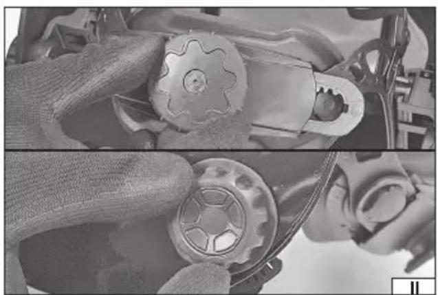
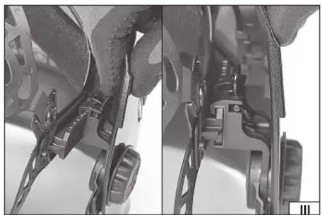
Put the helmet on your head, adjust the position of the upper headband strap, if necessary, to make sure the helmet is at the right height. By turning the knob on the occipital strap, adjust the length of the strap so that it does not press the head while working and at the same time the helmet does not move during head movements (II). Use the side knobs to adjust the force needed to lower and lift the helmet (II). By pressing the clip at the attachment of the straps inside the visor, it is possible to adjust the distance of the visor from the face (III). When pressure is released, the helmet should lock into one of several positions (III). Make sure that both sides are set in the same position. On the inside of the helmet at the left and right knobs, there is an adjustment of the helmet angle at maximum lowering and raising. Raise the upper adjustment wing (IV) relative to the lower one, then lower and lock it in the desired position (IV).
The operation of the automatic welding fi lter
ATTENTION! Before starting work, ensure that the filter is set to the correct mode for the type of work to be carried out. It is forbidden to work with a non-functioning welding protection filter, as it can lead to irrecoverable damage to the eyesight.
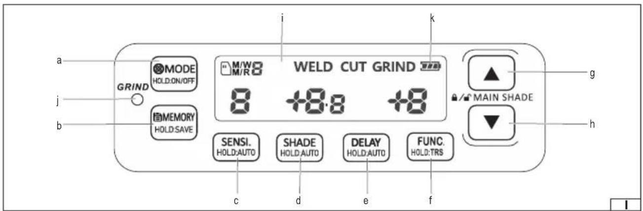
Control panel (I)
There are buttons on the control panel to control the operation of the filter. The buttons marked with two colours are dual-function. A short press will activate the first function, while pressing and holding the button for approximately 1 second will activate the
EN
second function. Button markings and messages on the display are in English. Parameter settings are made using the increase or decrease setting button. Below is a description of the buttons and functions of the welding filter:
a. operating mode button "MODE/HOLD:ON/OFF" – pressing and holding the button for approx. 1 second starts the filter operation. A short press of the button selects the operating mode indicated on the display: "WELD" – in this mode, it is possible to set the dark state between 9 and 14. "CUT" – in this mode, it is possible to set the dark state between 4 and 8. "GRIND" – in this mode the auto-dimming function is disabled and the filter will remain bright regardless of external conditions. The selection of bright mode is also indicated by a red light, labelled "GRIND" on the control panel. When the bright mode is selected, the indicator light will first illuminate with a continuous light and then illuminate intermittently.
b. Memory button marked "MEMORY, HOLD:SAVE" – 10 dark status settings can be stored in the memory of the welding filter. To save the set value, press and hold the memory button for approximately 1 second. The M/W symbol in the top left corner of the display will indicate the save function and the save location number will flash. Use the decrease or increase setting buttons to select a setting location number in the range of 1-9, and then wait approximately 6 seconds for the symbols to disappear to confirm. In order to save the set value in the storage space under no. 0, press and hold the memory button for approx. 1 second. The M/W symbol in the top left corner of the display will indicate the save function and the save location number will flash. Press and hold the memory button again for approx. 1 second, the storage location number will change to no. 0, then to save, wait approximately 6 seconds until the tags disappear.
Press the memory button briefly to load the stored value. In the upper left corner of the display, the M/R symbol will be displayed to indicate the loading function and the number of the storage location will flash. Use the down or up buttons to select the number of the setting to be loaded, in the range 1-9, and then wait approx. 6 seconds for the symbols to disappear before confirming. In order to load the stored value in the storage location under no. 0, press the memory button briefly. In the upper left corner of the display, the M/R symbol will be displayed to indicate the loading function and the number of the storage location will flash. Press and hold the memory button again for approx. 1 second, the storage location number will change to no. 0, then wait approx. 6 seconds for the tags to disappear to load the setting.
c. Sensitivity button labelled "SENSI., HOLD:AUTO" – a short press of the button adjusts the sensitivity, i.e. the threshold at which the filter is triggered in the dark state. The value to be set will start flashing on the display. Using the increase or decrease setting button, it is possible to set the sensitivity in the range 0-9. Setting "0" – indicates the lowest sensitivity, the filter will only react to a greater change in the intensity of light falling on the sensors. A setting of "9" and the display of the "SUPER" symbol – means the highest sensitivity, the filter will react to a smaller change in incident light intensity on the sensors. The "8" setting is recommended for most welding work, particularly when welding at low amperage. The set value is confirmed by pressing the sensitivity button again or the value will be confirmed automatically after approximately 6 seconds of inactivity.
Pressing and holding the sensitivity button for approximately 1 second triggers automatic sensitivity adjustment to the ambient conditions, which will be confirmed by the "AUTO" symbol appearing in front of the displayed value.
d. The darkening button labelled "SHADE, HOLD:AUTO" – a short press of the button allows for manual selection of the degree of darkening of the filter. The value to be set will start flashing on the display and a "MANUAL" symbol will be displayed near the value to be set. Depending on the selected shading mode, it is possible to select the degree of shading in the range of 4-8 in the operating mode marked "CUT" on the display or in the range of 9-14 in the mode marked "WELD" on the display using the increase or decrease button. The set value is confirmed by pressing the darkening button again or the value will be confirmed automatically after approximately 6 seconds of inactivity. Thanks to the sensors, the filter is automatically darkened to the set level when bright light from the welding process is detected. When choosing the dark state you can refer to the table in the manual showing the recommended protection levels for arc welding.
Pressing and holding the darkening button in the operating mode marked "WELD" on the display for approx. 1 second starts the automatic adjustment of the filter darkening. The auto-darkening deviation value will start to flash on the display and an "AUTO" symbol will be displayed close to the set value. Using the increase or decrease buttons, the deviation can be set between "-2" and "+2". The set value is confirmed by pressing the darkening button again or the value will be confirmed automatically after approximately 6 seconds of inactivity.
Pressing the increase and decrease setting buttons simultaneously allows the filter darkening to be locked at the selected level, regardless of the currently selected operating mode. Using the increase or decrease setting button, it is possible to select the degree of darkening between 4 and 14. The darkening of the filter is constant, independent of the change in incident light on the sensors. The filter darkening lock at the selected level can be deactivated by pressing the increase and decrease setting buttons simultaneously.
By pressing and holding the button labelled "TRS, HOLD:SIDE" for approximately 1 second, the filter's side windows can be darkened, regardless of the selected operating mode. The darkening of the filter's side glasses is constant, independent of the change in incident light on the sensors. To deactivate the side glass darkening lock, press and hold the button marked "TRS, HOLD:SIDE" again for approximately 1 second.
e. Delay button labelled "DELAY, HOLD:AUTO" – by briefly pressing the button, you can manually change the delay time of the filter, i.e. the time it takes the filter to react to a change in light intensity. The value to be set will start flashing on the display. Using
EN
the increase or decrease buttons, it is possible to set a switch-off time between 0 and 9 hours. The "0 TACK" setting indicates the smallest filter darkening delay suitable during tack welding. Setting "1" and "2" will be suitable for spot welding. A setting of "9" indicates the greatest filter darkening delay, suitable for most applications and particularly when welding at high amperage and longer intervals between welds.
By pressing and holding the delay button for approximately 1 second, the automatic delay can be set. The deviation value of the automatic delay will start to flash on the display and an "AUTO" symbol will be displayed near the set value. Using the increase or decrease buttons, the value can be set between "-9" and "+9". The set value is confirmed by pressing the delay button again or the value will be confirmed automatically after approximately 6 seconds of inactivity.
f. the gradient button marked "TRS, HOLD:SIDE" – briefly pressing the gradient button activates a function that allows for a smooth transition from the dark state to the light state. This function will not start if an automatic filter delay has been selected. The selection of the function will be confirmed by the "TRS" symbol appearing on the display. The selection of this function is not recommended for tack or spot welding.
g. setting increase button
h. setting decrease button
i. display
j. indicator light labelled "GRIND" – the selection of bright mode is signalled by a red light marked "GRIND" on the control panel. When the bright mode is selected, the indicator light will first illuminate with a continuous light and then illuminate intermittently.
k. battery indicator – the welding filter has a charge indicator for the power supply batteries. If the battery symbol on the display is full, the battery is fully charged. Gradual discharging of the battery is indicated by the reduction of the number of icons in the battery symbol. If the battery symbol is empty, the batteries must be replaced with a new set. Replacement of the power supply batteries is described later in this manual.
Operating mode toggle button
The mode change button on the outside of the cover is dual-function. By pressing and holding the button for approx. 1 second, you can quickly switch from dark mode to light mode or vice versa.
A short press of the button allows the dark status settings to be quickly saved under no. 0 in the welding filter memory.
Replacement of the batteries
The welding protection filter requires the CR 2450 battery to operate correctly. Always replace batteries in pairs. The battery compartment is located in the filter housing. Open the compartment cover and replace the batteries (V). Place the batteries in the battery compartment so that the positive terminal is on top. Snap the battery cover back in place. Run the filter and check the condition of the new battery. Dispose of the used battery in accordance with regional regulations governing the disposal of such materials.
Replacing the protective glass panels
Check the condition of the protective glass before each use. If scratches, cracks, clouding or other damage to the protective glass panels are found, they must be replaced. The front protective glass panel is mounted directly in the helmet. To replace the windscreen, pull out the plastic pin located on the right and left sides of the windscreen (VI). For easier removal, the pin clip located on the inside of the visor can be gently pulled back towards you and then slid outwards. Remove the glass (VI). Insert the new lens into the visor and then lock by inserting the pins until they lock into place. The front protective glass is available separately as YATO YT-73939.
The rear protective glass panels are mounted in the filter shell. To remove the protective glass of the filter, lift the glass at the notch, which is located on both sides of the glass, and then slide it out of the filter catches (VII). Bend the new glass slightly and then slide the side edges under the catches in the filter housing (VII). Do not bend the protective glass too strongly to avoid damaging it. To remove the protective glass of the filter side window, gently lever the glass and then slide it out of the filter catches (VIII). Slide the new glass under the catches in the filter housing. Replace the protective glass of the second side window in the same way. Note! It is forbidden to use the helmet without protective glass panels.
Removal of the welding fi lter
To remove the welding filter, the front visor must first be removed as described above. The next step is to remove the side glass of the filter. To do this, press the catches and then slide the side window out of the visor (IX). Repeat in the same way for the second side glass. In the next step, the mode change button must be removed. To do this, unscrew the nut securing the button and then dismantle as shown in the figure (X). Then remove the welding filter. To do this, carefully bend one filter clip by sliding it inwards (X) and slide the corner of the filter outwards from the visor. Repeat in the same way for the second fixing. In the next step, grasp the lower edge of the control panel and slide the filter out of the catches on the outside of the visor (XII). Remove the cable that connects the filter to the mode change button housing from the attachment located inside the visor (XII). Reassemble the filter in the reverse order of removal. Ensure that all filter catches are properly engaged and the filter will not move during operation.
EN
Working with the welding helmet
The filter installed in the helmet shell will work automatically if it is illuminated by the electric arc generated during welding. The response time is 1/25,000 seconds. Before welding, make sure that the welding filter is set to the dark state appropriate for the type of welding to be performed. If during operation you notice that the filter is not automatically darkening, stop working immediately and adjust the filter. If, despite adjustment, the filter does not function properly, contact an authorised service centre of the importer. It is forbidden to work with a non-functioning welding protection filter, as it can lead to irrecoverable damage to the eyesight. Temperature range of the working environment is from -5°C to +55°C. The filter is not designed to protect the eyesight during laser welding.
Operating instructions
Filter sensors should be kept clean and not obscured. In the automatic welding protection filter with manual adjustment, the maximum and minimum degree of protection is when the adjustment is set to zero. Eye protection against high-speed particles, worn in conjunction with standard corrective glasses, can transmit the impact, posing risk to the user.
Note! If high-speed particle impact protection is required at extreme temperatures, the selected eye protection device should be marked with the letter T immediately after the letter identifying the impact symbol, i.e. FT, BT or AT. If the letter indicating the impact symbol is not directly in front of the letter T, then the eye protection can only be used to protect against high-speed particles at room temperature.
Maintenance, storage and transport
After finishing work, clean the helmet with a soft and damp cloth. Larger instances of soil should be removed with soapy water and dried with a cloth. Do not use abrasive cleaning agents. Do not use solvents to clean the filter and the helmet. Do not immerse the welding filter in water. The product should be stored in supplied unit packaging in a dark, dry, ventilated and closed room. During storage, do not exceed the temperature range of -20°C to +70°C . Protect against dust, dirt and other contaminants (plastic bags, handbags, etc.) Protect against mechanical damage. Transport in the supplied unit packaging in carton boxes using closed transport.
Declaration of Conformity: Available at toya24.pl in the product data sheet.
Table of recommended protection levels for arc welding
| Process | Current [A] | |||||||||||||||||||||||||||||
| 1.5 6 | 10 15 | 80 40 | 60 70 | 100 125 | 150 175 | 200 225 | 250 | 300 | 350 | 400 | 450 | 500 | 600 | |||||||||||||||||
| Covered electrodes 8 9 | 10 11 | 12 13 | 14 | |||||||||||||||||||||||||||
| MAG | 8 | 9 | 10 | 11 | 12 | 13 | 14 | |||||||||||||||||||||||
| TIG | 8 | 9 | 10 | 11 | 12 | 13 | ||||||||||||||||||||||||
| MIG for heavy metals | 9 | 10 | 11 | 12 | 13 | 14 | ||||||||||||||||||||||||
| MIG for light alloys | 10 | 11 | 12 | 13 | 14 | |||||||||||||||||||||||||
| Arc gouging | 10 | 11 | 12 | 13 | 14 | 15 | ||||||||||||||||||||||||
| Plasma cutting | 9 | 10 | 11 | 12 | 13 | |||||||||||||||||||||||||
| Microplasma welding | 4 | 5 | 6 | 7 | 8 | 9 | 10 | 11 | 12 | |||||||||||||||||||||
| 1.5 6 | 10 15 | 80 40 | 60 70 | 100 125 | 150 175 | 200 | 225 | 250 | 300 | 350 | 400 | 450 | 500 | 600 | ||||||||||||||||
| NOTE! The term “heavy metals” is used for steel, steel alloys, copper, copper alloys, etc. | ||||||||||||||||||||||||||||||
DE
- DE
- OPERATING INSTRUCTIONS
- ADJUSTMENT OF THE HELMET SUPPORT SYSTEM
- THE OPERATION OF THE AUTOMATIC WELDING FI LTER
- CONTROL PANEL (I)
- EN
- OPERATING MODE TOGGLE BUTTON
- REPLACEMENT OF THE BATTERIES
- REPLACING THE PROTECTIVE GLASS PANELS
- REMOVAL OF THE WELDING FI LTER
- WORKING WITH THE WELDING HELMET
- MAINTENANCE, STORAGE AND TRANSPORT
Brand : Yato
Model : YT-73938
Category : Auto welding mask