PRTO2.0 - Hydraulic crimping tool MSW - Free user manual and instructions
Find the device manual for free PRTO2.0 MSW in PDF.

| Brand | MSW |
| Model | MSW-PRTO2.0 |
| Product type | Hydraulic crimping tool |
| Power supply | Li-ion battery 18 V / 4 Ah (2 batteries included) |
| Charging voltage | 240 V~, 50 Hz |
| Rated power | 73 W |
| Maximum crimping force | 120 kN |
| Crimping range | Copper up to 400 mm², Aluminum up to 300 mm² |
| Piston stroke | 42 mm |
| Crimping time per cycle | 5 to 8 seconds |
| Runtime per charge | Approximately 120 crimps (Cu cable 150 mm²) |
| Charging time | 80 minutes |
| Operating temperature | -10 °C to +40 °C |
| Dimensions (L x W x H) | 42 x 8 x 32 cm |
| Weight | 7.3 kg |
| Included crimping dies | 16, 25, 35, 50, 70, 95, 120, 150, 185, 240, 300, 400 mm² |
| Included accessories | 2 batteries, 1 charger, seal ring sets |
| Display | OLED screen (crimping time, battery level, error codes) |
| Main functions | MCU control system, auto reset, retraction stop, manual rearming, dual piston pump |
| Safety | Auto shut-off in case of overheating (motor >60°C), protection against hazardous operations, dual safety protection |
| Lighting | Built-in LED (20 s delay) |
| Recommended hydraulic oil | Shell Tellus T15# S2V HV15 |
| Oil capacity | 160 ml |
| Maintenance | Clean after each use, replace oil once a year, apply anti-rust oil |
| Reparability | Maintenance by qualified technician, use of identical spare parts |
Frequently Asked Questions - PRTO2.0 MSW
User questions about PRTO2.0 MSW
0 question about this device. Answer the ones you know or ask your own.
Ask a new question about this device
Download the instructions for your Hydraulic crimping tool in PDF format for free! Find your manual PRTO2.0 - MSW and take your electronic device back in hand. On this page are published all the documents necessary for the use of your device. PRTO2.0 by MSW.
USER MANUAL PRTO2.0 MSW
natural_image
Line drawing of a robotic arm with articulated joints and base mount (no text or symbols)natural_image
Teal handheld device connected to a black sensor with a string, showing wiring and a small head (no visible text or symbols)natural_image
Two electronic devices with a red arrow indicator, one black and one teal, against a white background (no text or symbols visible)3. Crimpvorgang
1

natural_image
3D rendering of a robotic arm with visible wiring and adjustment knob (no text or symbols)natural_image
3D rendering of a blue oil pump tool with red arrows pointing to the oil drop (no text or symbols on the diagram itself)Öl mit Maschinenöl
6

natural_image
3D rendering of a robotic arm with a hand adjusting the base (no text or symbols visible)This User Manual has been translated using machine translation. We have made every effort to ensure the translation is accurate, but please note that automated translations are not perfect and are not meant to replace human translators. The official version of the User Manual is in English. Any differences between the translated version and the original English are not legally binding. If you have any questions about the accuracy of the translation, please refer to the English version, which is the official reference. More language versions are available upon request via info@expondo.com
| Parameter description | Parameter value |
| Product name | Hydraulic crimping tool |
| Model | MSW-PRTO2.0 |
| Charging voltage [V~] / frequency [Hz] | 240 / 50 |
| Rated power [W] 73 | |
| Battery voltage [v] 18 | |
| Battery capacity [Ah] 4 | |
| Max. crimping force [kN] | 120 |
| Crimping range Cu 400mm2 / Al 300mm2 | |
| Stroke [mm] | 42 |
| Hydraulic oil: | Shell Tellus T15# S2V HV15 |
| Oil capacity [ml] 160 | |
| Time per crimp [sec] | 5-8 (depending on cable size) |
| Crimps per charge Approx. 120 crimps (CU 150 mm2) | |
| Charging time [min] 80 | |
| Ambient temperature [°C] -10 – +40 | |
| Dimensions [cm] | 42x8x32 |
| Weight [kg] | 7.3 |
Accessories:
| Crimping dies: | 16 / 25 / 35 / 50 / 70 / 95 /120 / 150 / 185 / 240 / 300 / 400 mm^2 |
| Battery: | 2 pieces |
| Charger: | 1 piece |
| Sealing ring of cylinder: | 1 set |
| Sealing ring of safety valve: | 1 set |
natural_image
Line drawing of a robotic arm with articulated joints and base mount (no text or symbols)Due to continuing improvements, the actual product may differ slightly from the product described herein.

Read this material before using this product.
Failure to do so can result in serious injury.
SAVE THIS MANUAL
SAVE THIS MANUAL
Keep this manual for important safety warnings, precautions, assembly, operation, inspection, maintenance, and cleaning procedures. Record the month and year of purchase. Store this manual and the receipt in a safe, dry place for future reference.
IMPORTANT SAFETY INFORMATION
In this manual, on the labeling, and all other information provided with this product:

This is the safety alert symbol. It is used to alert you to potential personal injury hazards. Obey all safety messages that follow this symbol to avoid possible injury or death.
DANGER indicates a hazardous situation which, if not avoided, will result in death or serious injury.
WARNING indicates a hazardous situation which, if not avoided, could result in death or serious injury.
CAUTION, used with the safety alert symbol, indicates a hazardous situation which, if not avoided, could result in minor or moderate injury.
GENERAL SAFETY RULES
To operate this tool safely, it is essential to carefully read and follow all instructions in this manual.
1. Work area safety
a) Keep the work area clean and clear. Cluttered or dark areas invite accidents.
b) This tool is not insulated; please do not use it on live conductors.
c) Avoid using or storing the tool in high temperatures or areas containing corrosive fluids. Regularly inspect for aging of the sealing kits.
d) Keep children and bystanders away while operating the battery-powered tool. Distractions can cause a loss of control.
2. Electrical safety
a) Ensure that the plug fits properly into the outlet. Do not alter the plug.
b) Do not expose the tool's battery or charger to rain or wet conditions. Water entering the electric system can cause an electric shock.
c) Avoid using the electric wire to carry or pull the plug. Damaged or tangled wires may cause an electric shock.
d) If the charger is damaged (e.g., dropped or crushed), do not attempt to repair it yourself. Return it to an authorized service center.
e) Charge the tool in temperatures between 10^ C and 40^ C. Ensure the air vents of the battery and charger remain uncovered during charging.
f) Disconnect the charger when not in use to reduce hazards for children or untrained individuals.
g) Do not overcharge the battery. Recharging when fully discharged may render the battery non-functional. Store the battery outside of the tool to prevent discharge.
h) Do not burn or short-circuit the battery, as it may cause an explosion.
i) If any issues arise, contact the manufacturer or agent; do not disassemble the battery or charger.
3. Personal safety
a) Remain alert and use common sense when operating the tool. Do not use the tool when tired, under the influence of drugs, alcohol, or medication. Inattention may result in serious injury.
b) Wear appropriate safety equipment, such as a mask, helmet, safety cap, and insulating shoes.
c) Avoid wearing loose clothing or jewelry and keep hair and gloves away from moving parts. Loose clothing or long hair can get caught in moving parts.
d) Maintain power tools in good condition. Check for misalignment, binding of moving parts, or broken components that could affect operation. If damaged, have the tool repaired before use.
e) Use the tool as intended, with the correct power settings, for optimal and safe operation.
f) Keep fingers away from the tool's head during operation to avoid injury.
4. Service
Have your crimping tool serviced by a qualified technician, using only identical replacement parts. This ensures safety and proper functionality.
SPECIFIC SAFETY RULES
1) Maintain labels and nameplates on the tool as they contain important safety information. If they become unreadable or missing, contact the agent for a replacement.
2) This product is not a toy, keep it out of reach of children.
3) Ensure the tool's head is locked securely before operation.
4) Do not use the tool without dies.
5) Do not crimp live cables or conductors.
6) Only crimp copper (Cu) or aluminum (Al) conducting materials.
7) Do not knock or damage any parts of the tool, as this may cause injury.
8) Do not operate the tool continuously. After 30-40 cycles, allow the tool to cool for 15 minutes.
9) Do not secure this tool in a vise. This tool is designed for hand-held operation.
10) The built-in safety valve undergoes strict pressure tests. Do not adjust the pressure unless performed by a professional.
11) The warnings, precautions, and instructions discussed in this instruction manual cannot cover all possible conditions and situations that may occur. It must be understood by the operator that common sense and caution are essential when using the device.
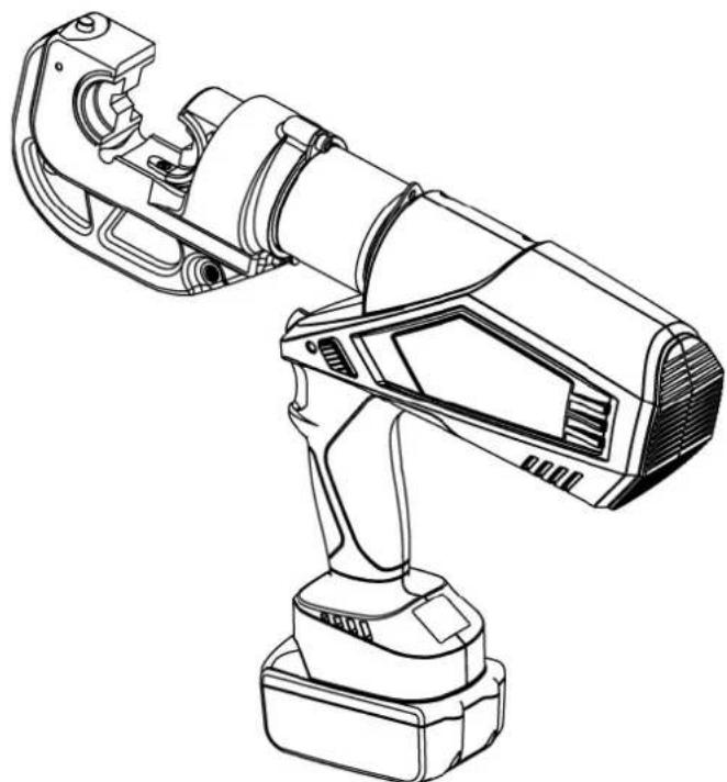
UNDERSTAND YOUR TOOL
The product is a crimping tool designed for Cu/Al lugs, suitable for cables ranging from 16 to 400 mm ^2 . Powered by a Li-ion battery, it features a motor-actuated system controlled by an MCU, an OLED display, and a high-pressure hydraulic mechanism. This makes it an ideal tool for use on electrical construction sites.
1. Description of components:
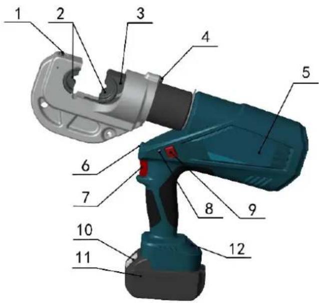
| Parts No. | Description | Function |
| 1 | Pin | For locking/unlocking the upper die |
| 2 Die For crimping, interchangeable crimping die | ||
| 3 | Retaining clips | For locking/unlocking the lower dies |
| 4 | Limited block | For preventing head from dropping or popping |
| 5 | Label | For company logo |
| 6 | Light (LED) | For lighting |
| 7 | Start button | For starting operation |
| 8 | Retract button | Manually retracts the piston in case of incorrect operation |
| 9 | LED indicator (red LED) | Indicates the tool's operating condition and battery status |
| 10 | OLED display | Displays crimping times, battery level, and error information |
| 11 | Battery lock | For locking/unlocking the battery. |
| 12 | Battery | For supplying power, rechargeable Li-ion (18V) |
3. Function description

Microcomputer control system – Automatically detects pressure during crimping and provides double safety protection.

OLED display – Dot matrix OLED display shows crimping times, battery power, working pressure (if equipped with a pressure sensor), maintenance reminders, and fault codes.

Auto reset – Automatically releases pressure and retracts the piston to the starting position when maximum output is reached.

Retraction stop – During multiple crimps, press the start button again to stop the piston from retracting and continue working, improving efficiency.

Manual reset – Allows the piston to retract to the starting position in case of incorrect operation.

The unit is equipped with a double piston pump which allows the rapid approach of the die towards the connector and a slow crimping motion for precision.

The unit is equipped with a double piston pump which allows the rapid approach of the die towards the connector and a slow crimping motion for precision.
If a deviation from set pressure or low battery is detected, an acoustic signal will sound, and the red display will flash.

The compact structure, non-slip rubber grip, and optimized center of gravity make operation easier.

A temperature sensor automatically stops the tool when the motor surface temperature exceeds 60^ C. The tool will resume operation once cooled.
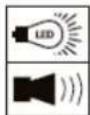
Table 1. Signal Instruction and Meaning:
| Number | Instruction | LED(red) | LED(white) |  | OLED screen Meaning | |
| 1 | Self-checking | (2Hz) |  | Self-checking to ensure everything is functioning correctly | ||
| 2 | Light | Delay 20s off |   | Indicates the tool is in working state, battery fully charged | ||
| 3 | Charging reminder | (2Hz) |  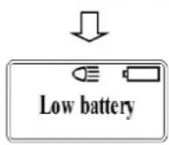 | Lacking power and need charging. | ||
| (5s) | Ⓞ (2Hz) |  | Battery low, requires charging | |||
| (100ms) |  | Screen unresponsive, battery must be replaced | ||||
| 4 | Motor overload | (2Hz) | Ⓞ (2Hz) |  | Motor stuck, battery reloading, recovery work interface | |
| 5 | Hydraulic system malfunction | (5s) | Ⓞ (5s) | 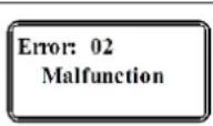 | Hydraulic pressure not released, if nothing changes after 2 minutes, reload the battery | |
| 6 | High temperature warning | (2Hz) | Ⓞ (2Hz) |  | Motor surface temperature is too high, allow to device to cool and restart | |
| 7 | Dangerous operation protection | (2Hz) | Ⓞ (2Hz) |  | Auto-protection when press the start button on and off quickly, reload battery | |
| 8 | Maintenance reminder | Ⓞ (0.5s) | 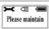  | Tool must be maintained | ||
Read the entire SAFETY INFORMATION section at the beginning of this manual including all text under subheadings therein before using this product.
Use this tool for the manufacture's intended purpose only. Use other than that which is described in this manual can result injury or property damage.
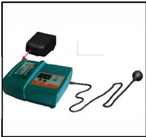
1. Charging
Insert the battery into the charger and connect the plug to the designated socket. Ensure that the room temperature is between 10^ C and 40^ C. The charging time is approximately 80 minutes. Refer to the illustration below for further details.
1
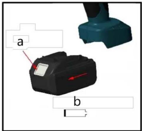
- a - Push the lock
• b - Remove the battery
2
natural_image
Illustration of a digital testing device connected to a probe and a string, with no visible text or symbols.- Insert the battery into the charging station
3

- Keep in appropriate ambient temperature
4
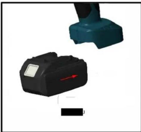
natural_image
Two electronic devices with a red arrow indicator, one black and one teal, against a white background (no text or symbols visible)- Insert the battery into the device holder
For detailed charging information, please refer to the "Charging Manual."
CAUTION!
1) The battery can be used hundreds of times. However, if you notice a significant reduction in performance, please replace the battery with a new one.
2) Charge the battery promptly to prevent it from being completely drained, as this may render it permanently unusable. If the battery is not used for an extended period, it will discharge automatically. Ensure to charge the battery at least once every quarter.
3) Do not connect the two battery terminals with a wire, as this may cause an electric spark, fire, or even an explosion.
4) Do not use or charge a damaged battery, as this increases the risk of electric shock.
5) Never burn batteries under any circumstances, as they may explode.
6) When charging the battery, do not cover the charger with any objects, as this may prevent proper heat dissipation and could cause a fire.
7) Disconnect the charger when not in use to reduce the risk of injury to children and untrained personnel.
8) Do not use the charger in a humid environment, and avoid exposure to rain or snow, as this increases the risk of electric shock.
9) Do not disassemble the battery or charger without authorization. If any issue arises during use, consult a professional or contact the manufacturer for repair until the problem is resolved.
2. Usage of the tool
OLED display interface description:
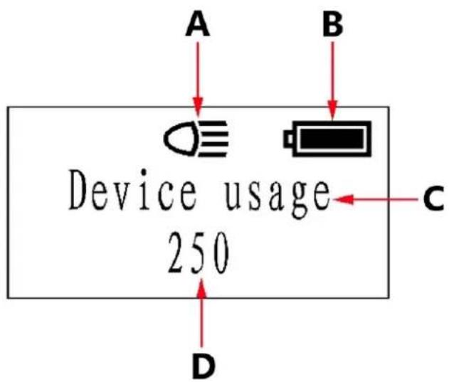
A - LED light
B - Battery status
C - Information display area
D - Cumulative crimping times
Tool LED illuminator:
- When the start button is pressed, the LED illuminator will turn on.
- After releasing the tool, the LED light will automatically turn off after a 20-second delay.
• Before installing the battery, press the start button. - Once the battery is installed, release the start button to turn off the LED light.
• If the LED light remains on, reinstall the battery.
Please refer to the image for further clarification.
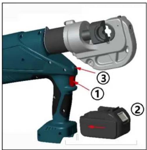
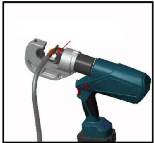
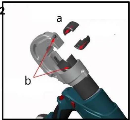
3. Crimping operation
1

a – Insert the pin
b – Insert dies
2
natural_image
3D rendering of a robotic arm with visible wiring and adjustment knob (no text or symbols)Insert the cable
3
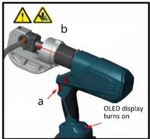
a – Press the button
b – Piston extends to crimp
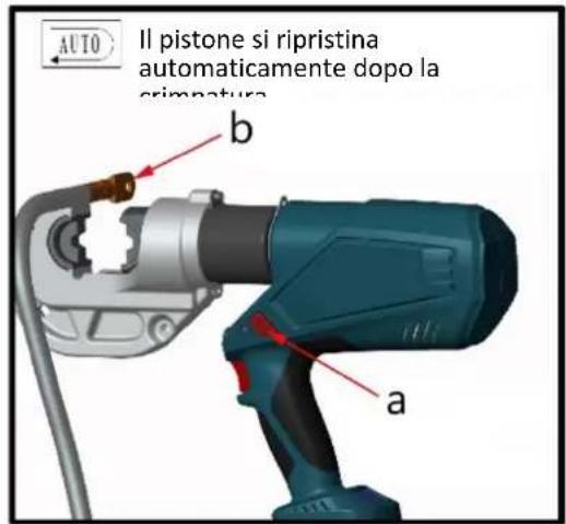
4

a – Remove cable when finished crimping
b-Piston auto-resets
5
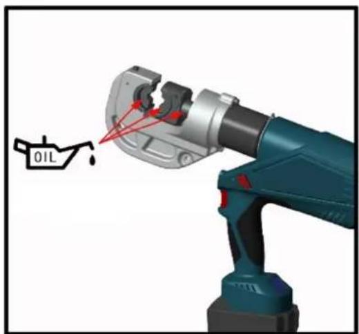
natural_image
3D rendering of a blue oil pump tool with red arrows pointing to the oil drop (no text or symbols on the diagram itself)Oil with machine oil
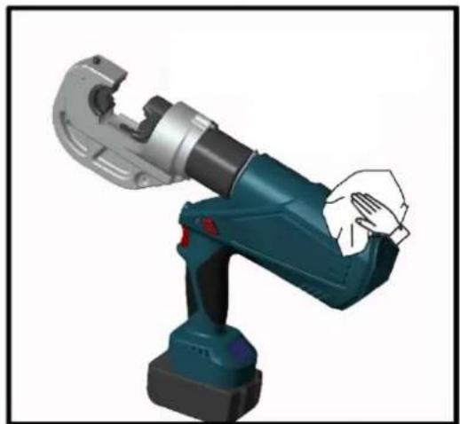
6

natural_image
3D rendering of a robotic arm with a hand adjusting the grip (no text or symbols visible)Wipe clean and store in the box
MAINTENANCE AND SERVICING
WARNING!
Damaged equipment can lead to serious personal injury. Do not use damaged equipment. If you notice abnormal noise or vibration, stop use immediately and have the issue resolved before continuing.
1) Before each use, check the overall condition of the tool. Look for loose screws, misalignment or binding of moving parts, cracked or broken parts, or any other issue that could affect safe operation.
2) After each use, clean the tool's external surfaces with a clean, damp cloth. Apply rust-preventive oil to the metal surfaces and dies to avoid rusting. Store the tool in a dry environment.
3) Tool servicing should only be carried out by a qualified service technician.
4) To prolong the tool's lifespan, replace the oil once a year. Ensure the oil is filtered through a 120-mesh filter or a strainer of 30 m or finer. Take care to prevent dust from entering the oil cup.
5) After extended use, the sealing kits may wear out. If there is leakage, contact the manufacturer or distributor to replace the sealing kits.
6) If the tool is not used for a long period, ensure the piston is in its starting position, clean the tool, and apply rustproof oil to both the tool and its accessories. Remove the battery and store it in a box and place the tool in a dry environment.
TROUBLESHOOTING
| FAULT | POSSIBLE CAUSES | SOLUTION |
| A. Tool is inoperative 1. Dirt or contaminants in the ram area of the tool.Battery is depleted.Tool components are worn or damaged. | 1. Clean the hydraulic system.Charge the battery.Return the tool to the manufacturer or distributor for repair. | |
| B. No power during operation or not reaching rated power | 1. No oil in the system.Dirt or contaminants in the oil sac.Internal leakage. | 1. Fill the oil.Return the tool to the manufacturer or distributor.Return the tool to the manufacturer or distributor. |
| C. Crimp is not tight 1. Tool is not reaching rated power.Incorrect selection of crimping die. | 1. Refer to solutions in Fault B.Return the tool to the manufacturer or distributor. | |
| D. Excessive scrap production | 1. Incorrect selection of crimping die. | 1. Select the correct crimping die. |
| E. Leakage on the head or plunger | 1. Worn sealing kits. 1. Return the tool to the manufacturer or distributor for sealing kit replacement. | |
| F. Motor is running, but no power output | 1. No oil in the oil sac.Air trapped in the hydraulic system.Oil is too cold. | 1. Fill or replace the oil.Return the tool to the manufacturer or distributor to remove air from the system.Operate the tool within the temperature range of -10°C to 40°C. |

natural_image
Line drawing of a robotic arm with articulated joints and base mount (no text or symbols)natural_image
Medical device with digital display and attached probe, connected to a string (no visible text or symbols)natural_image
Two electronic devices with a red arrow indicator, one black and one teal, against a white background (no text or symbols visible)natural_image
3D rendering of a robotic arm with a highlighted oil drop component (no text or symbols)natural_image
3D rendering of a robotic arm with visible wiring and mechanical components (no text or symbols)Włóż kabel
4

natural_image
3D rendering of a robotic arm with hands gripping it (no text or symbols visible)natural_image
Line drawing of a robotic arm with articulated joints and base mount (no text or symbols)natural_image
Medical device with digital display and earplifier, no visible text or symbolsnatural_image
Two electronic components with a red arrow indicating direction, one black and one teal, against a white background (no text or symbols)natural_image
3D rendering of a robotic arm with visible wiring and adjustment knob (no text or symbols)Vložte kabel
3

natural_image
3D rendering of a blue oil pump tool with red arrows pointing to the oil drop (no text or symbols on the diagram itself)natural_image
3D rendering of a robotic arm with a hand adjusting the grip (no text or symbols visible)natural_image
Line drawing of a robotic arm with articulated joints and base mount (no text or symbols)natural_image
Medical device with teal casing connected to a black sensor and a white ball (no visible text or symbols)natural_image
Two electronic devices with a red arrow indicator, one black and one teal, against a white background (no text or symbols visible)natural_image
3D rendering of a robotic arm with a highlighted oil drop component (no text or symbols on the object)natural_image
3D rendering of a robotic arm with visible wiring and mechanical components (no text or symbols)Insérer le câble
4

natural_image
3D rendering of a robotic arm with hands gripping it (no text or symbols visible)natural_image
Line drawing of a robotic arm with articulated joints and base mount (no text or symbols)natural_image
Teal handheld device connected to a black sensor with a string, showing no visible text or symbols.natural_image
Two electronic components with a red arrow indicator, one black and one teal, against a white background (no text or symbols)natural_image
3D rendering of a mechanical robotic arm with a labeled oil drop symbol (no text or symbols on the robot itself)natural_image
3D rendering of a robotic arm with visible wiring and adjustment knob (no text or symbols)Inserire il cavo
4
natural_image
3D rendering of a robotic arm with a hand gripping the shaft (no text or symbols visible)natural_image
Line drawing of a robotic arm with articulated joints and base mount (no text or symbols)natural_image
Medical device with attached probe and cord, no visible text or symbolsnatural_image
Two electronic devices with a red arrow indicator, one black and one teal, against a white background (no text or symbols visible)natural_image
3D rendering of a robotic arm with a highlighted oil drop component (no text or symbols on the robot itself)natural_image
3D rendering of a robotic arm with visible wiring and mechanical components (no text or symbols)Insertar el cable
4

natural_image
3D rendering of a robotic arm with a hand gripping the shaft (no text or symbols visible)natural_image
Line drawing of a robotic arm with articulated joints and base mount (no text or symbols)natural_image
Medical device with digital display and earplifier connected by a cord (no visible text or symbols)natural_image
Two electronic components with a red arrow indicating direction, one black and one teal, against a white background (no text or symbols)natural_image
3D rendering of a robotic arm with visible wiring and adjustment knob (no text or symbols)natural_image
3D rendering of a blue oil pump tool with red arrows pointing to the oil drop (no text or symbols on the diagram itself)Olaj gépolajjal
6

natural_image
3D rendering of a robotic arm with a hand adjusting the grip (no text or symbols visible)natural_image
Line drawing of a robotic arm with articulated joints and base mount (no text or symbols)natural_image
Medical device with digital display and attached black sensor, connected to a terminal pole (no visible text or symbols)- Sæt batteriet ind i ladestationen
3

- Opbevares ved passende omgivelsestemperatur
4

natural_image
Two electronic devices with a red arrow indicator, one black and one teal, against a white background (no text or symbols visible)3. Krympeoperation
1

natural_image
3D rendering of a robotic arm with visible wiring and adjustment knob (no text or symbols)Sæt kablet i
4

natural_image
3D rendering of a robotic arm with a hand adjusting the base (no text or symbols visible)natural_image
Line drawing of a robotic arm with articulated joints and base mount (no text or symbols)natural_image
Medical device with digital display and attached probe, connected to a string (no visible text or symbols)natural_image
Two electronic components with a red arrow indicating direction, one black and one teal, against a white background (no text or symbols)3. Puristustoiminto
1

natural_image
3D rendering of a robotic arm with visible wiring and adjustment knob (no text or symbols)natural_image
3D rendering of a blue oil pump tool with red arrows pointing to the oil drop (no text or symbols on the diagram itself)Öljy koneöljyllä
6
natural_image
3D rendering of a robotic arm with a hand adjusting the base (no text or symbols visible)natural_image
Line drawing of a robotic arm with articulated joints and base mount (no text or symbols)natural_image
Illustration of a digital testing device connected to a probe and a sensor (no text or symbols visible)natural_image
Two electronic devices with a red arrow indicator, one black and one teal, against a white background (no text or symbols visible)3. Krimpbewerking
1 2
natural_image
3D rendering of a robotic arm with visible wiring and joints (no text or symbols)Kabel insteken
3 4

natural_image
3D rendering of a robotic arm with a hand gripping the joint (no text or symbols visible)natural_image
Line drawing of a robotic arm with articulated joints and base mount (no text or symbols)natural_image
Medical device with digital display and earplifier connected by cord (no visible text or symbols)natural_image
Two electronic components with a red arrow indicating direction, one black and one teal, against a white background (no text or symbols)D - Kumulative krympetider
Verktøy LED-belysning:
3. Krympeoperasjon
1

a – Sett inn pinnen b – Sett inn dyser
2

natural_image
3D rendering of a robotic arm with visible wiring and adjustment knob (no text or symbols)Sett inn kabelen
3

natural_image
3D rendering of a blue oil pump tool with red arrows pointing to the oil drop (no text or symbols on the diagram itself)Olje med maskinolje
6