S-POWER UPS 800 PSW - Solar panel MSW - Free user manual and instructions
Find the device manual for free S-POWER UPS 800 PSW MSW in PDF.

| Product Type | Solar UPS System with Inverter/Charger |
| Model | S-POWER 800 PSW Inverter |
| Rated Power | 800 W / 1000 VA |
| AC Output Voltage | 230 V / 50 Hz |
| AC Output Current | 4.3 A |
| Output Waveform | Pure Sine Wave |
| Battery Input Voltage (DC) | 24 V |
| MPPT PV Range | 30 - 66 V DC |
| Max PV Open Circuit Voltage | 75 V DC |
| Recommended Max PV Power | 1000 W |
| Max Battery Charge Current | 40 A |
| Dimensions (L x W x H) | 270 x 130 x 350 mm |
| Weight | 6.6 kg |
| Efficiency | 98% |
| Operating Temperature | 0°C to 55°C |
| Storage Temperature | -15°C to 60°C |
| Compatible Battery Type | Lead-acid, GEL, AGM (deep discharge) |
| Protection Functions | Overload, overheat, short-circuit, overvoltage, battery undervoltage |
| Display | LCD with LED indicators |
| Communication | RS232, USB, dry contact |
| Maintenance | Clean with a soft cloth, check connections, do not expose to water |
| Repairability | Repairs by qualified professional only, genuine parts recommended |
Frequently Asked Questions - S-POWER UPS 800 PSW MSW
User questions about S-POWER UPS 800 PSW MSW
0 question about this device. Answer the ones you know or ask your own.
Ask a new question about this device
Download the instructions for your Solar panel in PDF format for free! Find your manual S-POWER UPS 800 PSW - MSW and take your electronic device back in hand. On this page are published all the documents necessary for the use of your device. S-POWER UPS 800 PSW by MSW.
USER MANUAL S-POWER UPS 800 PSW MSW
natural_image
Technical line drawing of a computer drive showing internal components and external ports (no text or labels)natural_image
Diagram of an industrial control panel with labeled ports and arrows indicating orientation (no text or symbols present)BATTERIEANSCHLUSS
natural_image
Technical line drawings of an electrical control unit with internal components and mounting base (no text or symbols)TROCKENKONTAKTSIGNAL
This User Manual has been translated for your convenience using machine translation. Reasonable efforts have been made to provide an accurate translation; however, no automated translation is perfect nor is it intended to replace human translators. The official User Manual is the English version. Any discrepancies or differences created in the translation are not binding and have no legal effect for compliance or enforcement purposes. If any questions arise related to the accuracy of the information contained in the User Manual, please refer to the English version of those contents which is the official version.
Technical data
| Parameter description | Parameter value | ||
| Product name | UPS solar power system | ||
| Model | S-POWER UPS800 PSW | S-POWER UPS4000 PSW | S-POWER UPS1600 PSW |
| INVERTER MODE | |||
| AC Output Voltage [V] / Frequency [Hz] / Current [A] | 230 / 50 / 4.3 | 230 / 50 / 22 | 230 / 50 / 8.7 |
| Rated Power [VA] / [W] | 1000 / 800 | 5000 / 4000 | 2000 / 1600 |
| DC Input Voltage [V] / Current [A] | 24 / 33 | 48 / 87 | 24 / 66 |
| Dimensions [Width x Depth x Height; mm] | 270 x 130 x | 295 x 130 x | 270 x 130 x |
| 350 | 470 | 370 | |
| Weight [kg] | 6.6 | 10.4 | 6.9 |
| Efficiency [%] | 98 | ||
| Operating Temperature Range [°C] | 0 - 55 | ||
| Storage Temperature [°C] | -15 ~ 60 | ||
| Input Voltage Waveform | Sinusoidal | ||
| Output Voltage Waveform | Pure Sine Wave | ||
| SOLAR CHARGER MODE | |||
| System Voltage [V DC] | 24 | 48 | 24 |
| Maximum PV Array Power [W] | 1000 4000 | 1000 | |
| MPPT Range at Operating Voltage [V DC] | 30-66 | 60-115 | 30-66 |
EN
| Maximum PV Array Open Circuit Voltage [V DC] | 75 145 75 | ||
| Maximum Charging Current [A] | 40 80 40 | ||
| AC CHARGING MODE | |||
| AC Input Voltage [V] / Frequency [Hz] / Current [A] | 230 / 50 / 7.4 | 230 / 50 / 36 | 230 / 50 / 13.4 |
| DC Output Voltage [V] / Current [A] | 27 / 10/20 | 54 / 10-60 | 27/ 20/30 |
| AC Output Voltage [V] / Frequency [Hz] / Current [A] | 230 / 50 / 4.3 | 230 / 50 / 22 | 230 / 50 / 8.7 |
1. General description
The user manual is designed to assist in the safe and trouble-free use of the device. The product is designed and manufactured in accordance with strict technical guidelines, using state-of-the-art technologies and components. Additionally, it is produced in compliance with the most stringent quality standards.
DO NOT USE THE DEVICE UNLESS YOU HAVE THOROUGHLY READ AND UNDERSTOOD THIS USER MANUAL.
To increase the product life of the device and to ensure trouble-free operation, use it in accordance with this user manual and regularly perform maintenance tasks. The technical data and specifications in this user manual are up to date. The manufacturer reserves the right to make changes associated with quality improvement. The device is designed to reduce noise emission risks to a minimum, taking into account technological progress and noise reduction opportunities.
Legend
The product satisfies the relevant safety standards.
Read instructions before use.
 | The product must be recycled. | |
 | WARNING! or CAUTION! or REMEMBER! Applicable to the given situation.(general warning sign) | |
 | ATTENTION! Electric shock warning! | |
 | Only use indoors. |

PLEASE NOTE! Drawings in this manual are for illustration purposes only and in some details may differ from the actual product.
2. Usage safety
ATTENTION! Read all safety warnings and all instructions. Failure to follow the warnings and instructions may result in electric shock, fire and/or serious injury or even death.
The terms "device" or "product" are used in the warnings and instructions to refer to: ups solar power system.
2.1. Electrical safety
a) The plug must fit the socket. Do not modify the plug in any way. Using original plugs and matching sockets reduces the risk of electric shock.
b) Use the cable only for its designated use. Never use it to carry the device or to pull the plug out of a socket. Keep the cable away from heat sources, oil, sharp edges or moving parts. Damaged or tangled cables increase the risk of electric shock.
c) Do not use the device if the power cord is damaged or shows obvious signs of wear. A damaged power cord should be replaced by a qualified electrician or the manufacturer's service centre.
d) To avoid electric shock, do not immerse the cord, plug or device in water or other liquids. Do not use the device on wet surfaces.
e) Do not use in very humid environments or in the direct vicinity of water tanks.
f) Prevent the device from getting wet. Risk of electric shock!
g) This device should be connected to a permanent grounded wiring system.
h) Only a qualified personnel can install this device with battery.
2.2. Safety in the workplace
a) If there are any doubts as to the correct operation of the device, contact the manufacturer's support service.
b) Only the manufacturer's service point may repair the device. Do not attempt any repairs independently!
c) In case of fire, use a powder or carbon dioxide (CO2) fire extinguisher (one intended for use on live electrical devices) to put it out.
d) Children or unauthorized persons are forbidden to enter a work station. (A distraction may result in loss of control over the device).
e) Use the device in a well-ventilated space.
f) Regularly inspect the condition of the safety labels. If the labels are illegible, they must be replaced.
g) Please keep this manual available for future reference. If this device is passed on to a third party, the manual must be passed on with it.
h) If this device is used together with another equipment, the remaining instructions for use shall also be followed.
2.3. Personal safety
a) The device is not designed to be handled by persons (including children) with limited mental and sensory functions or persons lacking relevant experience and/or knowledge unless they are supervised by a person responsible for their safety or they have received instruction on how to operate the device.
b) The device can be handled only by physically fit persons who are capable of handling it, properly trained, familiar with this manual and trained within the scope of occupational health and safety.
c) To prevent the device from accidentally switching on, make sure the switch is on the OFF position before connecting to a power source.
d) The device is not a toy. Children must be supervised to ensure that they do not play with the device.
2.4. Safe device use
a) Do not overload the device. Use the appropriate tools for the given task. A correctly-selected device will perform the task for which it was designed better and in a safer manner.
b) Do not use the device if the ON/OFF switch does not function properly (does not switch the device on and off). Devices which cannot be switched on and off using the ON/OFF switch are hazardous, should not be operated and must be repaired.
c) When not in use, store in a safe place, away from children and people not familiar with the device who have not read the user manual. The device may pose a hazard in the hands of inexperienced users.
d) Keep the device out of the reach of children.
e) Device repair or maintenance should be carried out by qualified persons, only using original spare parts. This will ensure safe use.
f) To ensure the operational integrity of the device, do not remove factory-fitted guards and do not loosen any screws.
g) When transporting and handling the device between the warehouse and the destination, observe the occupational health and safety principles for manual transport operations which apply in the country where the device will be used.
h) Do not move, adjust or rotate the device in the course of work.
i) The device is not a toy. Cleaning and maintenance may not be carried out by children without supervision by an adult person.
j) It is forbidden to interfere with the structure of the device in order to change its parameters or construction.
k) Keep the device away from sources of fire and heat.
I) Do not overload the device.
m) Do not cover the ventilation openings!
n) To reduce the risk of injury, charge only deep-cycle lead-acid type of rechargeable batteries. Other type of batteries may burst, causing personal injury or damage.
o) Never charge a frozen battery.

ATTENTION! Despite the safe design of the device and its protective features, and despite the use of additional elements protecting the operator, there is still a slight risk of accident or injury when using the device. Stay alert and use common sense when using the device.
3. Use guidelines
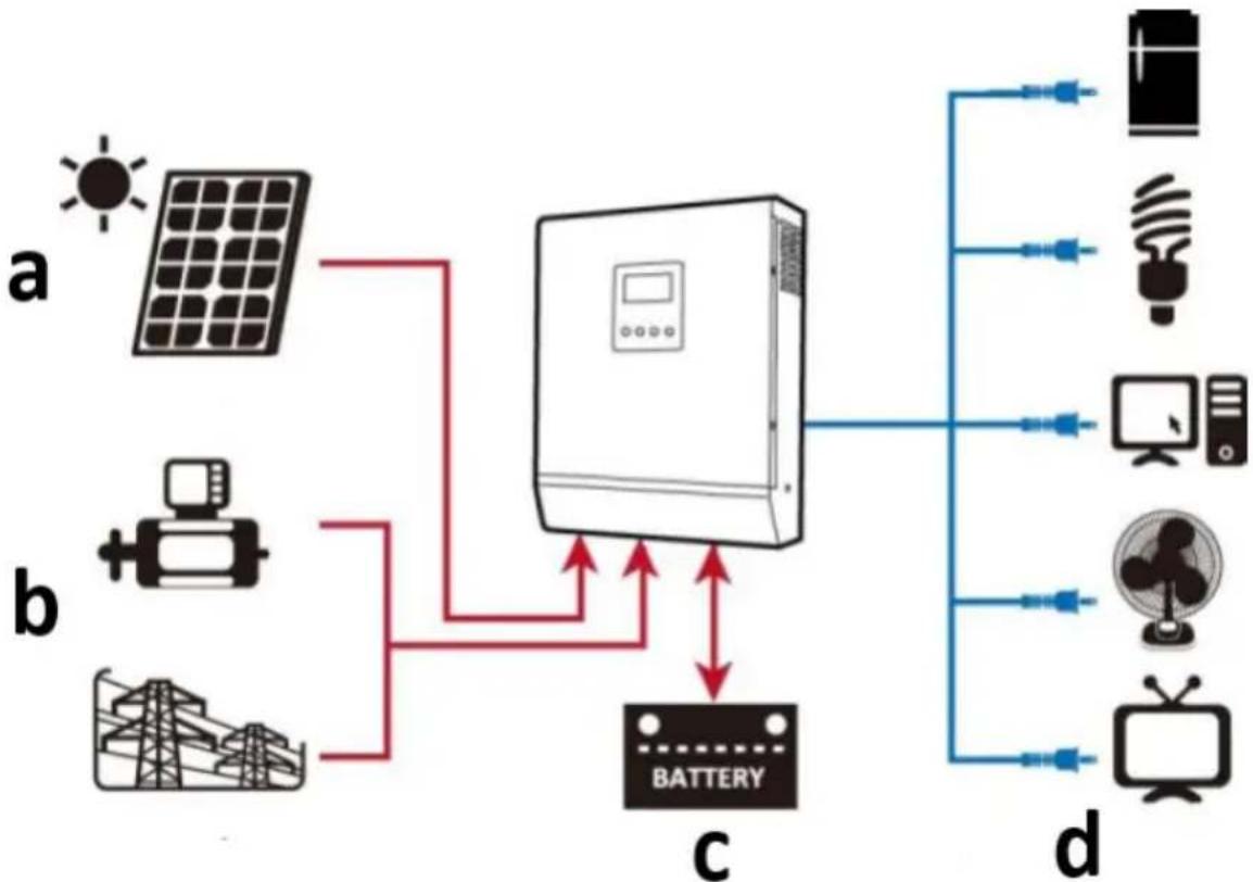
This product is a multi-function inverter/charger, combining functions of inverter, solar charger and battery charger to offer uninterruptible power support. It offers a user-configurable and easy-accessible operation through control panel.
- Configurable input voltage range for home appliances and personal computers.
- Configurable battery charging current based on applications.
- Configurable AC/Solar charger priority.
• Compatible to mains voltage or generator power.
• Auto restart while AC is recovering.
• Overload-/ excessive temperature-/ short circuit-protection.
• Smart battery charger design for optimized battery performance. - Cold start function.
The following illustration shows basic application for this product as a hybrid power system:
flowchart
graph TD
    A["Sun"] --> B["Device"]
    C["Solar Panel"] --> B
    D["Battery"] --> B
    E["Pump Lamp"] --> B
    F["Power Source"] --> B
    G["Power Source"] --> B
    H["Power Source"] --> B
    I["Battery"] --> B
    J["Battery"] --> B
    K["Power Source"] --> B
    L["Power Source"] --> B
    M["Power Source"] --> B
    N["Power Source"] --> B
    O["Power Source"] --> B
    P["Power Source"] --> B
    Q["Power Source"] --> B
    R["Power Source"] --> B
    S["Power Source"] --> B
    T["Power Source"] --> B
    U["Power Source"] --> B
    V["Power Source"] --> B
    W["Power Source"] --> B
    X["Power Source"] --> B
    Y["Power Source"] --> B
    Z["Power Source"] --> B
    AA["Power Source"] --> B
    AB["Power Source"] --> B
    AC["Power Source"] --> B
    AD["Power Source"] --> B
    AE["Power Source"] --> B
    AF["Power Source"] --> B
    AG["Power Source"] --> B
    AH["Power Source"] --> B
    AI["Power Source"] --> B
    AJ["Power Source"] --> B
    AK["Power Source"] --> B
    AL["Power Source"] --> B
    AM["Power Source"] --> B
    AN["Power Source"] --> B
    AO["Power Source"] --> B
    AP["Power Source"] --> B
    AQ["Power Source"] --> B
    AR["Power Source"] --> B
    AS["Power Source"] --> B
    AT["Power Source"] --> B
    AU["Power Source"] --> B
    AV["Power Source"] --> B
    AW["Power Source"] --> B
    AX["Power Source"] --> B
    AY["Power Source"] --> B
a) Solar power (optional)
b) Generator or utility mains
c) External battery pack
d) Appliances
The user is liable for any damage resulting from unintended use of the device.
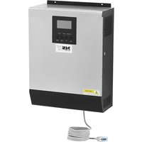
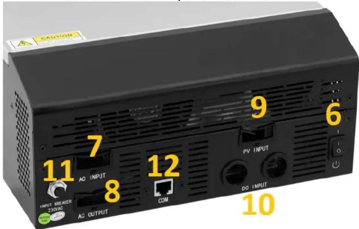
3.1. Device description
S-POWER UPS 800 PSW / S-POWER UPS 1600 PSW:
S-POWER UPS 4000 PSW:
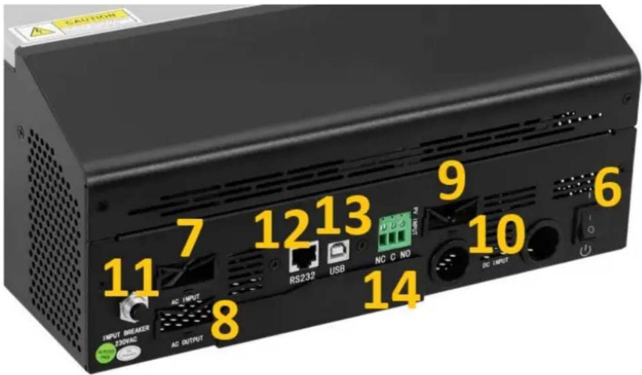
- LCD Display
- Status indicator
- Charging indicator
- Fault indicator
- Function buttons
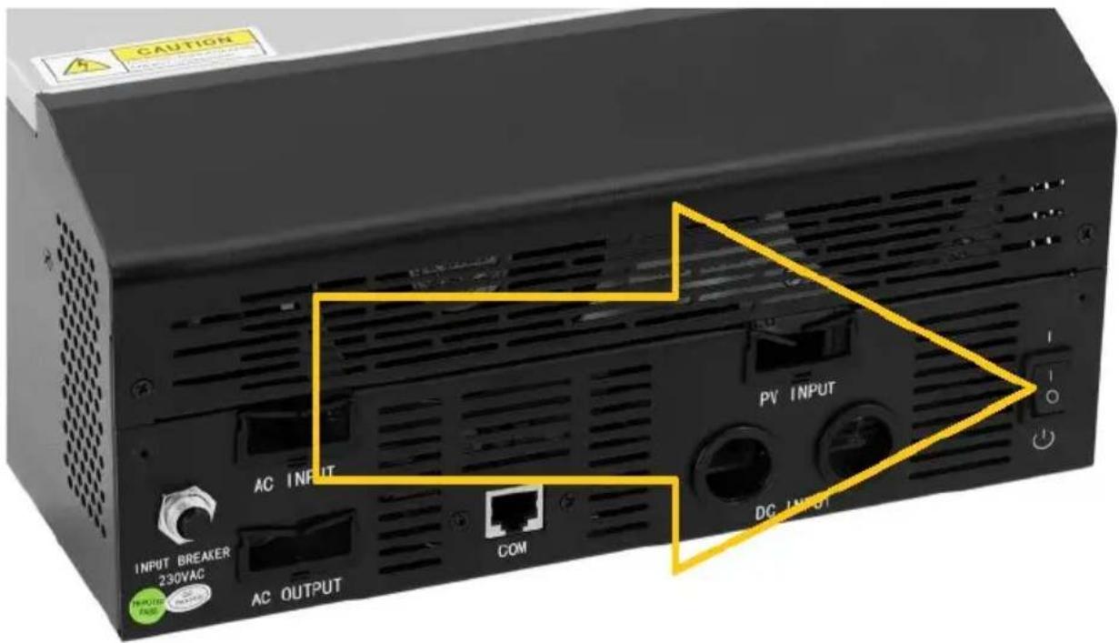
- Power ON/OFF switch
- AC input
- AC output
- PV input
- Battery (DC) input
- Circuit breaker
- RS232 communication port
- USB communication port
- Dry contact (voltage free)
3.2. Preparing for use
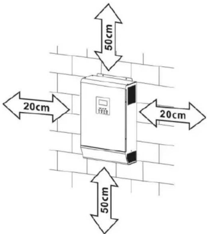
APPLIANCE LOCATION
• Installation must be performed by a professional electrician.
- Do not mount the inverter on flammable construction materials.
- Mount it on a solid, stable surface like for ea. concrete.
- Install the appliance at eye level in order to allow the LCD-display to be readable all the time.
- For proper air circulation and heat dissipation allow it approx. 20 cm to the sides and approx. 50 cm above and below the unit.
- The ambient temperature should be between 0 °C and 55°C to ensure optimal operation.
- The recommended installation position is fixed vertical on the wall.
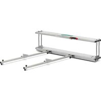
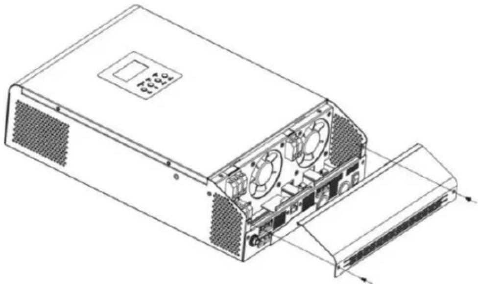
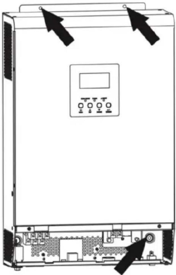
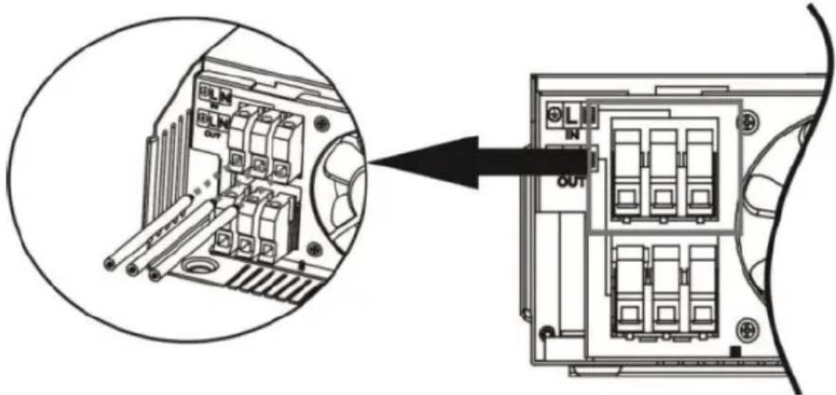
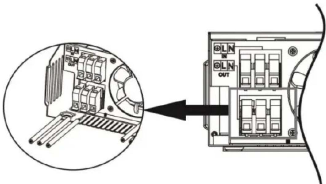
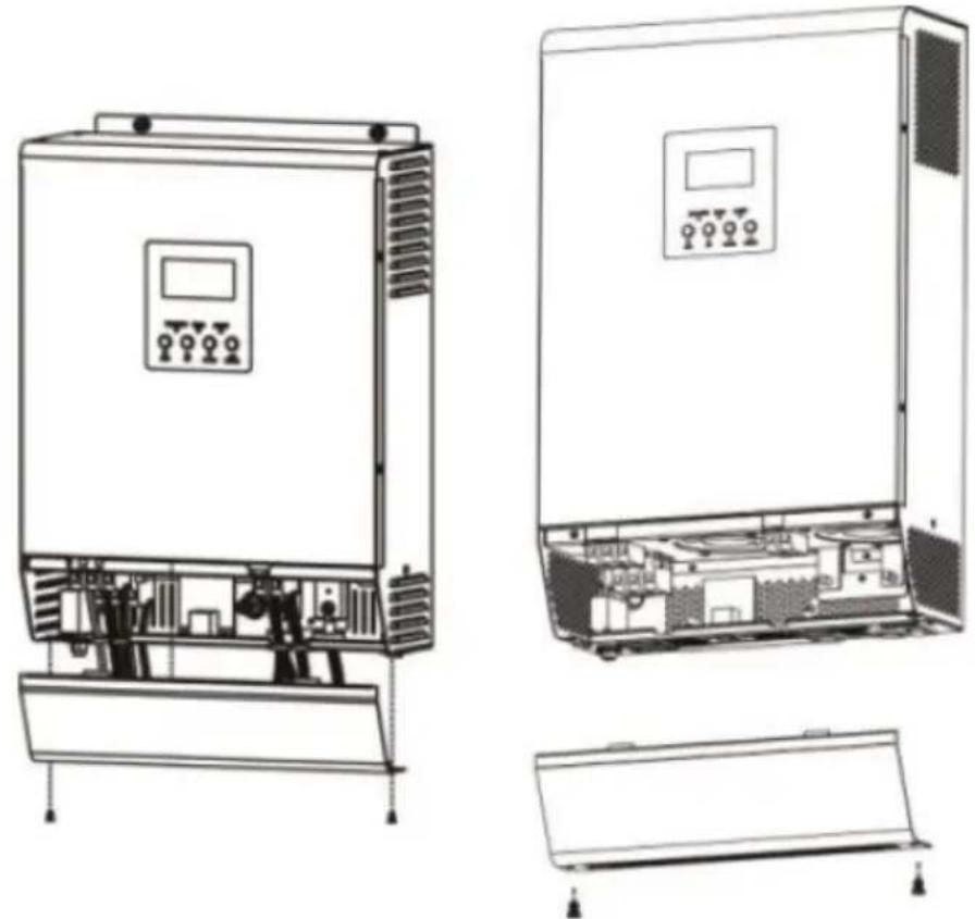
- Before connecting all wires, take off the bottom cover by removing 2 screws as shown below:
natural_image
Technical line drawing of a computer power supply unit showing internal components and external casing (no text or labels)- Unit fixing points as indicated (recommended to use M4 or M5 screws):
natural_image
Technical line drawing of a server rack with control panel and drive unit (no text or symbols)BATTERY CONNECTION
For safety and regulation it is required to install a separate DC over-current protection. It is very important of safety and efficiency reason to use proper recommended cable and terminal size:
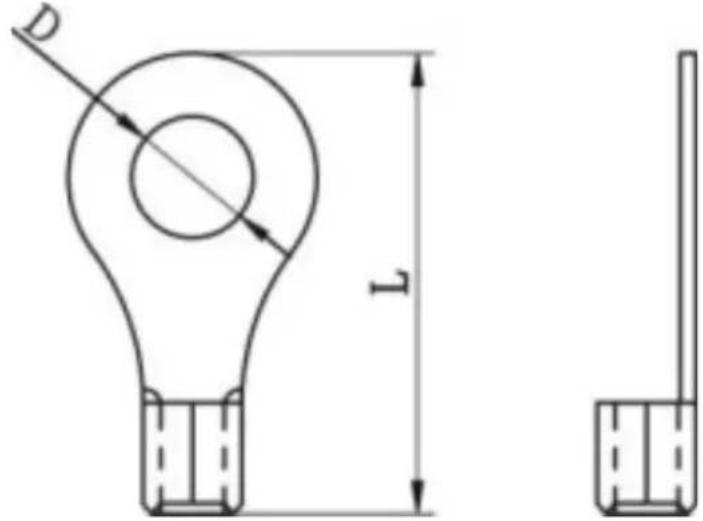
| Recommended battery cables and terminal size: | ||||||
| Model | Typical amperag | Battery capacit | Wire size | Ring terminal | Torque | |
| Cabl | Dimensions | |||||
| e | y (at least) | e mm2 | D (mm ) | L (mm ) | value | ||
| S-POWER UPS800PSW/S-POWER UPS1600PSW | 83A 100Ah | 1*4AWG | 22 | 23.86.4 | 29.2 | 2~3Nm | |
| 2*8AWG | 16 | ||||||
| S-POWER UPS4000PSW | 104A 200Ah | 1*2AWG | 38 | ||||
| 2*6AWG | 28 | ||||||
| Battery connection diagram: | |||||||
| S-POWER UPS800PSW | 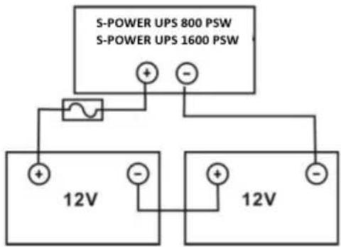 | ||||||
| S-POWER UPS1600PSW | |||||||
| S-POWER UPS4000PSW | 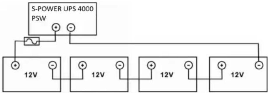 | ||||||
EN
NOTE: use only lead-acid battery or sealed GEL/AGM lead-acid battery!
Insert the ring terminal of battery cable flatly into battery connector of inverter and make sure the bolts are properly tightened – watch for correct polarity both the battery and the inverter/charger terminals.
CAUTION: do not apply antioxidant substance on the terminals before they are connected tightly.
CAUTION: before making the final DC connection or closing DC breaker/disconnector, be sure positive (+) must be connected to positive (+) and negative (-), must be connected to negative (-).
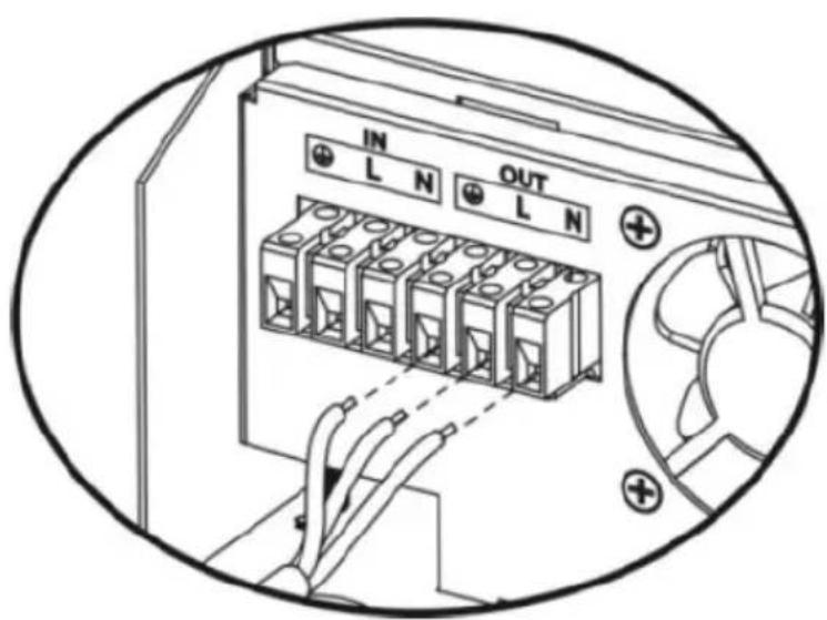
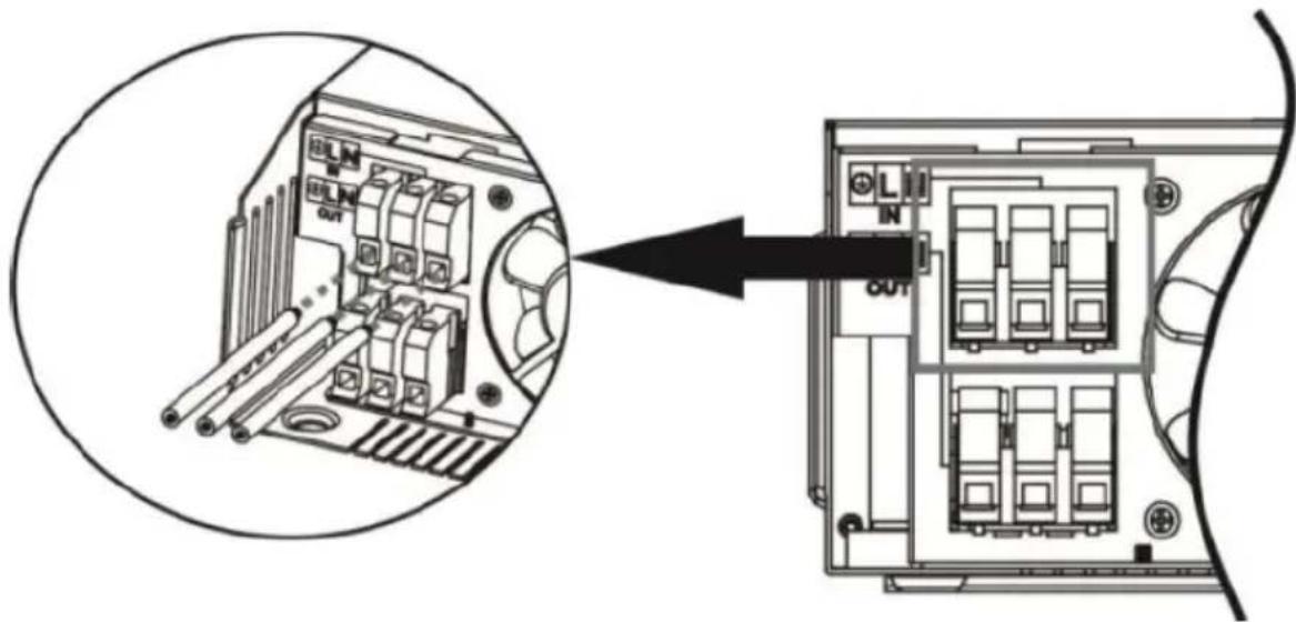
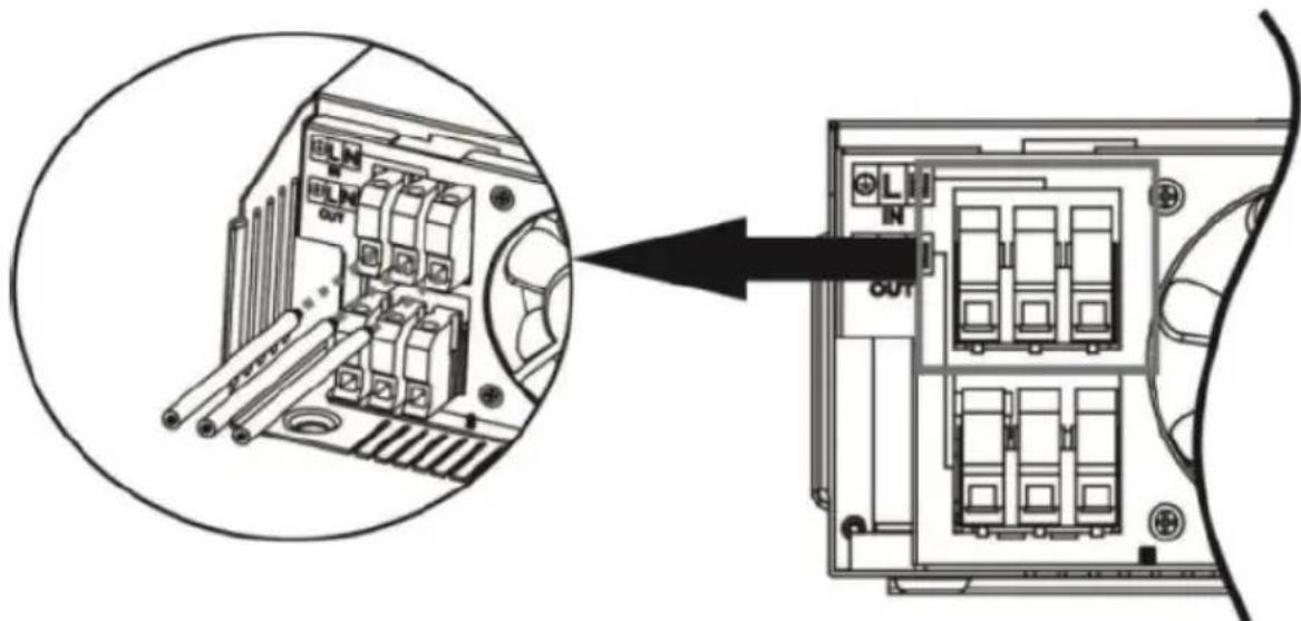
AC INPUT/OUTPUT CONNECTION
CAUTION: before connecting to AC input power source, install a separate AC breaker between inverter and AC input power source. This will ensure the inverter can be securely disconnected during maintenance and fully protected from overcurrent of AC input. Recommended spec of AC breaker is 10A for 1000VA, 20A for 2000VA and 50A for 5000VA.
NOTE: there are two terminal blocks marked "IN" and "OUT" – do not miss-connect input and output connectors! It is important to for safety and efficiency reason to use appropriate cable for AC input connection as recommended below:
| Model | Gauge | Torque value |
| S-POWER UPS 800 PSW | 16 AWG | 0.5-0.6 Nm |
| S-POWER UPS 1600 PSW | 14 AWG 0.8-1.0 Nm | |
| S-POWER UPS 4000 PSW | 8 AWG 1.4-1.6 Nm |
To implement AC input/output connection:
a) Be sure to open the DC protector or disconnector first.
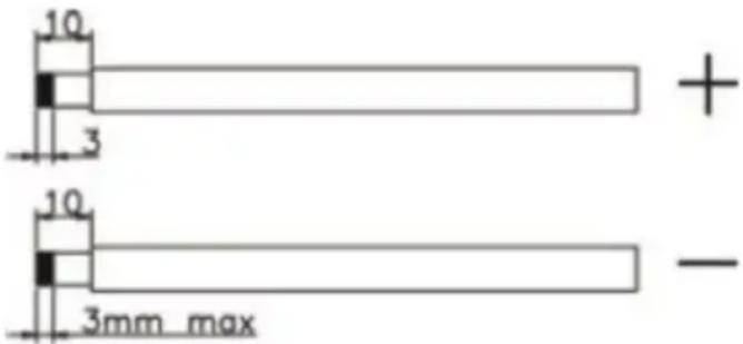
b) Remove insulation sleeve 10mm for six conductors and shorten phase L and neutral N 3mm.
c) Insert AC input wires according to polarities indicated on terminal block and tighten the terminal screws. Be sure to connect PE protective conductor first:
| Ground Yellow-green | ||
| L | Line | Brown or black |
| N | Neutral | Blue |
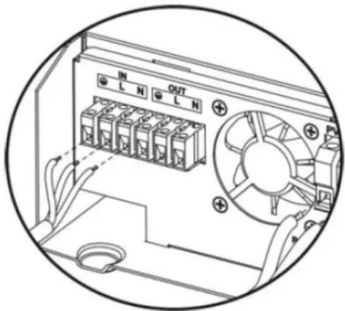
1000VA:
2000-5000VA:
WARNING: be sure the AC power source is disconnected before attempting to hardwire it to the unit.
d) Insert AC output wires according to polarities indicated on terminal block and tighten terminal screws. Be sure to connect PE protective conductor first:
| Ground Yellow-green | ||
| L | Line | Brown or black |
| N | Neutral | Blue |
1000VA:
2000-5000VA:
e) Make sure the wires are securely connected.
CAUTION: be sure to connect AC wires with correct polarity. If L and N wires are connected reversely, it may cause utility short-circuited when these inverters are worked in parallel operation.
EN
CAUTION: appliances such as air conditioner are required few minutes time delay to restart, because it is required to have enough time to balance refrigerant gas inside of circuits. If a power shortage occurs and recovers in a short time, it will cause damage to connected appliances. To prevent this kind of damage, please check if the air conditioner is equipped with time-delay function before installation. Otherwise the inverter/charger will trig overload fault and cut off output to protect your appliance but sometimes is still can cause damage to the air conditioner.
PV CONNECTION (ONLY APPLY FOR THE MODEL WITH SOLAR CHARGER) CAUTION: before connecting to PV modules, install separately a DC circuit breaker between inverter and PV modules. It is very important for safety and efficiency to use appropriate cable fir PV module connection. To reduce risk of injury, please use proper recommended cable size.
| Typical amperage | Gauge | Torque value |
| 40A | 12 AWG | 1.2~1.6 Nm |
When selecting proper PV modules, please be sure to consider below requirement first:
a) Open circuit voltage (Voc) of PV modules not exceeds max PV array open circuit voltage of inverter
| Model | S-POWER UPS800 PSW | S-POWER UPS4000 PSW | S-POWER UPS1600 PSW |
| Solar charger | |||
| Charging current (PWM) | 40A 80A 40A | ||
| System voltage DC | 24V 48V 24V | ||
| Operating voltage range | 30~66V DC | 60~115V DC | 30~115V DC |
| Max. PV array | |||
| open circuit voltage | 75V DC | 145V DC | 75V DC |
b) Max. power voltage (Vmpp) of PV modules should be close to best Vmp of inverter or within Vmp range to get best performance. If one PV module cannot meet this requirement, it is necessary to have several PV modules in series connection. Refer to below table:
| Model | Best Vmp | Vmp range |
| S-POWER UPS 800 PSW | 45V DC | 30~32V |
| S-POWER UPS 4000PSW | 100V DC | 60~145V |
| S-POWER UPS 1600PSW | 80V DC 30~115V |
NOTE: * Vmp: panel max power point voltage.
The PV charging efficiency is maximized while PV system voltage is close to Best Vmp.
Maximum PV module numbers in series: Vmpp of PV module * X pcs = Best Vmp of inverter or Vmp range.
PV module numbers in parallel: max. charging current of inverter / Impp
Total PV module numbers = maximum PV module numbers in series * PV module numbers in parallel.
The 1000VA inverter as an example to set proper PV modules. After considering Voc of PV modules not exceeds 50V DC and max. Vmpp of PV module close to 45V DC or within 30\~66V DC, we can choose PV module with below specification:
| Maximum power (Pmax) | 550W | Max PV module numbers in series 1→41.28x1=30~66 |
| Max. power voltage Vmpp | 41.28 V | |
| Max. Power current Impp | 13.33 A | |
| Open circuit voltage Voc | 49.8 V | |
| Short circuit current Isc | 14.01 A |
Maximum PV module numbers in series: 1
PV module numbers in parallel: N/A
Total PV module numbers: 1
The 5000VA inverter as an example to set proper PV modules. After considering Voc of PV modules not exceeds 150V DC and max. Vmpp of PV module close to 60V DC or within 60\~145V DC, we can choose PV module with below specification:
| Maximum power (Pmax) | 550 W | Max PV module numbers in series3→41.28x3=60~145 |
| Max. power voltage Vmpp | 41.28 V | |
| Max. Power current Impp | 13.33 A | PV module numbers in parallel3→40A/13.33 |
| Open circuit voltageVoc | 49.8 V | |
| total PV module numbers 3 | ||
| Short circuit current Isc | 14.01 A |
Maximum PV module numbers in series: 3
PV module numbers in parallel: 3
Total PV module numbers: 9
The 2000VA inverter as an example to set proper PV modules. After considering Voc of PV modules not exceeds 80V DC and max. Vmpp of PV module close to 80V DC or within 30\~115V DC, we can choose PV module with below specification:
| Maximum power (Pmax) | 550W | Max PV module numbers in series 1→41.28x1÷30~115 |
| Max. power voltage Vmpp | 41.28 V | |
| Max. Power current Impp | 13.33 A | |
| Open circuit voltage Voc | 49.8 V | |
| Short circuit current Isc | 14.01 A |
Maximum PV module numbers in series: 2
PV module numbers in parallel: N/A
Total PV module numbers: 2
Follow below steps to implement PV module connection:
a) Remove insulation sleeve 10mm for positive and negative conductors.
b) Check correct polarity of connection cable from PV modules and PV input connectors. Then connect positive pole (+) of connection cable to positive pole (+) of PV input connector. Connect negative pole (-) of connection cable to negative pole (-) of PV input connector.

c) Make sure the wires are securely connected.
FINAL ASSEMBLY
After connecting all wirings, put bottom cover back by screwing two screws shown below:
natural_image
Technical line drawings of an electrical control unit with internal components and mounting base (no text or symbols)COMMUNICATION CONNECTION
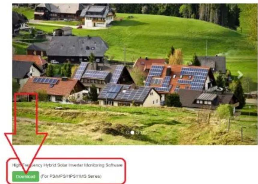
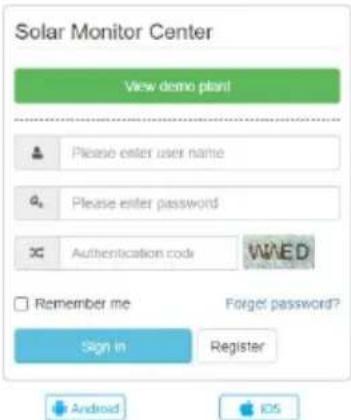
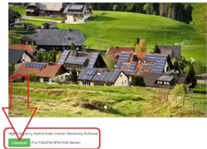
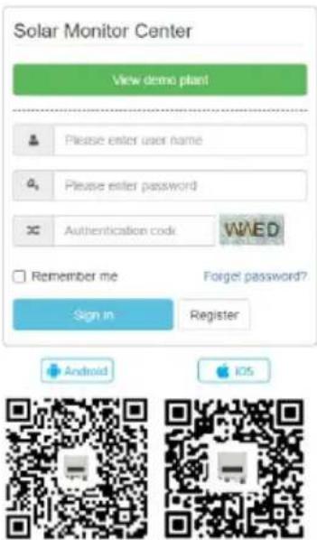
a) use the supplied communication cable to connect the inverter and PC. To monitor the system through a PC You need to install external software found in this link: http://solarmonitorsystem.com/

b) after downloading the file click it to install the software on Your PC.
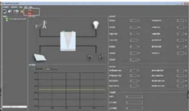
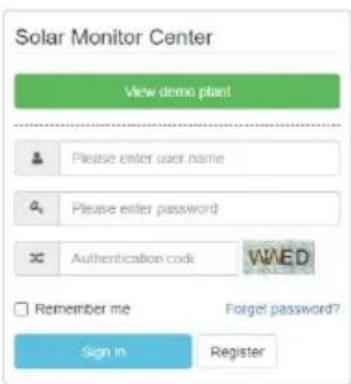
c) After finished installation run the software and first change its language to English:
| Flash | 2021-03-23 17:50 | 文件夹 | |
| Picture | 2021-03-23 17:50 | 文件夹 | |
| EntityFramework.dll | 2019-09-14 17:01 | 应用程序扩展 | 4,872 KB |
| EntityFramework.SqlServer.dll | 2019-09-14 17:01 | 应用程序扩展 | 578 KB |
| EntityFramework.SqlServer | 2019-09-14 17:01 | XML 文档 | 160 KB |
| EntityFramework | 2019-09-14 17:01 | XML 文档 | 3,650 KB |
| log4net.dll | 2020-09-28 16:07 | 应用程序扩展 | 270 KB |
| log4net | 2020-09-28 16:07 | XML 文档 | 1,480 KB |
| MpsDataBase | 2021-01-23 16:21 | Data Base File | 400 KB |
| MySql.Data.dll | 2015-10-02 23:04 | 应用程序扩展 | 447 KB |
| SolarPowerSystem | 2021-01-23 16:02 | 应用程序 | 173,287 KB |
| SolarPowerSystem.exe.config | 2021-01-06 11:57 | CONFIG 文件 | 2 KB |
| SolarPowerSystem.pdb | 2021-01-23 16:02 | PDB 文件 | 256 KB |
| System.Data.SQLite.dll | 2020-05-30 15:54 | 应用程序扩展 | 1,746 KB |
| System.Data.SQLite.EFG.dll | 2020-05-30 16:03 | 应用程序扩展 | 181 KB |
| System.Data.SQLite.Ling.dll | 2020-05-30 16:03 | 应用程序扩展 | 181 KB |
| System.Data.SQLite | 2020-05-30 16:03 | XML 文档 | 1,077 KB |
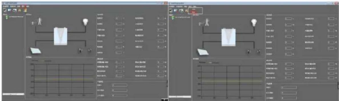
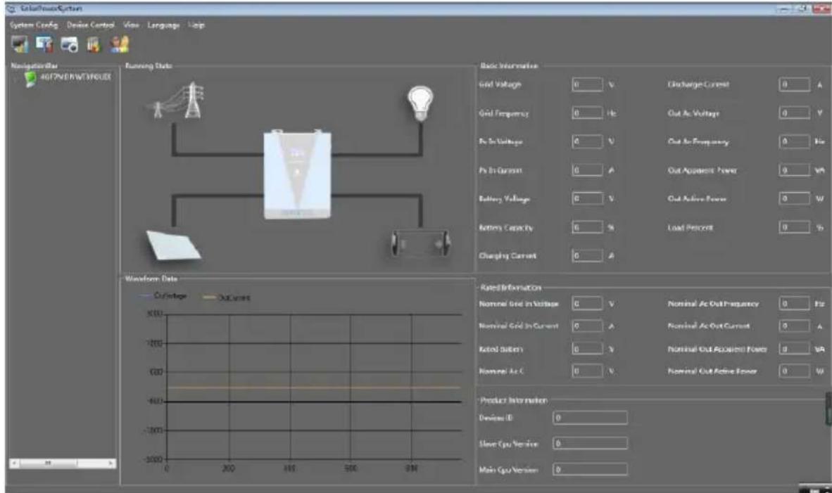
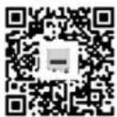
d) After software interface language change You can start using the software to monitor the UPS:
DRY CONTACT SIGNAL
There is one dry contact (3A/250V AC) available on the rear panel. It could be used to deliver signal to external device when battery voltage reaches warning level.
| Unit status | Condition | Dry contact port | |||
| NC & C | NO & C | ||||
| Power OFF | Unit is off and no output is powered. | Close | Open | ||
| Power ON | Output is powered from utility. | Close | Open | ||
| Output is powered frombattery or solar | Program 01 set as utility. | Battery voltage < Low DCwarning voltage | Open Close | ||
| Battery voltage > Setting value in Program 13 or battery charging reaches floating stage | Close Open | ||||
| Program 01 is set as SBU or solar first | Battery voltage < setting value in program 12 | Open Close | |||
| Battery voltage > Setting value in program 13 or battery charging reaches floating range | Close Open | ||||
3.3. Device use
POWER ON / OFF
Once the unit has been properly installed and the batteries are connected well, pressing the ON/OFF switch (located on the bottom of the case) will turn ON/OFF the unit.
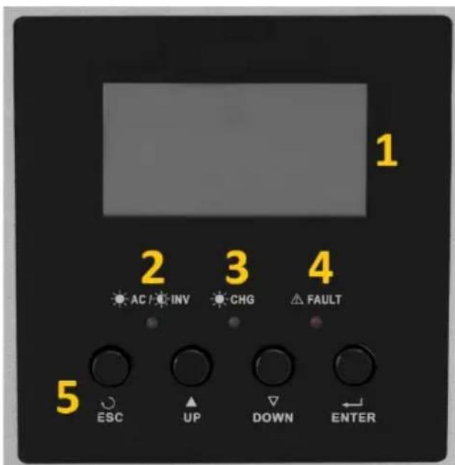
DISPLAY AND FUNCTION BUTTONS
The display panel with function buttons are located on the front of the appliance:
| Light indicator (LED) | Meaning | ||
 | Green | Solid ON | Output is powered by utility in line mode. |
| Flashing | Output is powered by battery or PV in battery mode. | ||
 | Green | Solid ON | Battery is fully charged. |
| Flashing | Battery is being charging. | ||
 | Red | Solid ON | Fault occurs in the inverter. |
| Flashing | Warning condition occurs in the inverter. | ||
| Function button | Description | ||
| ESC | To exit setting mode. | ||
| UP | To go to previous selection. | ||
| DOWN | To go to next selection. | ||
| ENTER | To confirm the selection in setting mode / Enter setting mode | ||
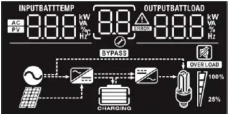
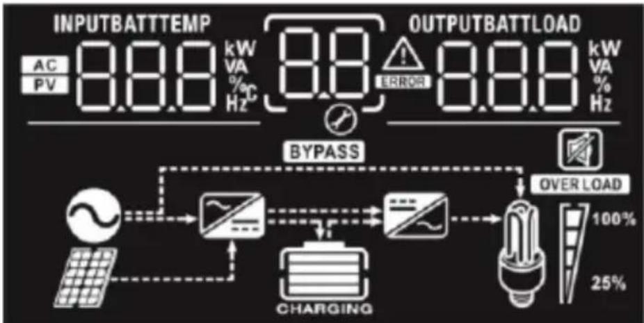
DISPLAY ICONS
flowchart
graph TD
    A["INPUTBATTTEMP AC PV 8.8.8 kW VA % Hz"] --> B["BYPASS"]
    C["OUTPUTBATTLOAD 8.8.8 kW VA % Hz"] --> D["OVER LOAD 100% 25%"]
    B --> E["Charging"]
    D --> E
    E --> F["Load"]
    style A fill:#f9f,stroke:#333
    style C fill:#f9f,stroke:#333
    style B fill:#ccf,stroke:#333
    style D fill:#ccf,stroke:#333
    style E fill:#cfc,stroke:#333
    style F fill:#fcc,stroke:#333
| Icon | Function description |
| Input source information | |
 | Indicates the AC input. |
 | Indicates the PV input. |
 BATT BATT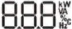 | Indicate input voltage, input frequency, PV voltage,battery voltage and charger current. |
| Configuration program and fault information | |
  | Indicates the setting programs. |
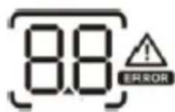 | Indicates the warning and fault codes.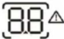 Warning: flashing with warning code. Warning: flashing with warning code.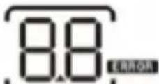 Fault: lighting with fault code. Fault: lighting with fault code. |
 | |
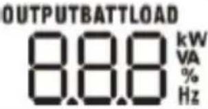 | Indicate output voltage, output frequency, load percent, load in VA, load in Watt and discharging current. | ||
| Battery information | |||
 | Indicates battery level by 0-24%, 25-49%, 50-74% and 75-100% in battery mode and charging status in line mode. | ||
| In AC mode, it will present battery charging status. | |||
| Status | Battery voltage | Display | |
| Constant current mode / Constant voltage mode | <2V/cell | 4 bars will flash in turns. | |
| 2 ~ 2.083V/cell | Bottom bar will be on and the other three bars will flash in turns. | ||
| 2,083 ~ 2.167V/cell | Bottom two bars will be on and the other two bars will flash in turns. | ||
| >2.167V/cell | Bottom three bars will be on and the top bar will flash. | ||
| Floating mode. Batteries are fully charged. | 4 bars will be on. | ||
| In battery mode, it will present battery capacity. | |||
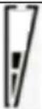
| Load percentage | Battery voltage | Display | |
| Load >50% | < 1.717V/cell |  | |
| 1.717V/cell ~ 1.8V/cell |  | ||
| 1.8 ~ 1.883V/cell |  | ||
| > 1.883V/cell |  | ||
| 50%> Load > 20% | < 1.817V/cell |  | |
| 1.817V/cell ~ 1.9V/cell |  | ||
| 1.9 ~ 1.983V/cell |  | ||
| > 1.983V/cell |  | ||
| Load < 20% | 1.867V/cell |  | ||||
| 1.867V/cell ~ 1.95V/cell | 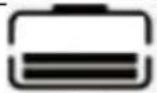 | |||||
| 1.95 ~ 2.033V/cell | 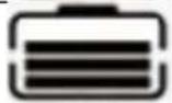 | |||||
| >2.033V/cell |  | |||||
| Load information | ||||||
| OVER LOAD | Indicates overload. | |||||
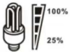 | Indicates load level by 0-24%, 25-50%, 50-74% and 75-100%. | |||||
| 0%~25% | 25%~50% | 50%~75% | 75%~100% | |||
 |  |  |  | |||
| Mode operation information | ||||||
 | Indicates unit connects to the mains. | |||||
 | Indicates unit connects to the PV panel. | |||||
 | Indicates load is supplied by utility power. | |||||
 | Indicates the utility charger circuit is working. | |||||
 | Indicates the DC/AC inverter circuit is working. | |||||
 | ||||||
 | Indicates unit alarm is disabled. | |||||
LCD SETTING
After pressing and holding "ENTER" button for 3 seconds, the unit will enter setting mode. Press "UP or "DOWN" button to select setting programs and then press "ENTER" button to confirm the selection or "ESC" button to exit.
Setting programs:
| Program | Description Selectable option | |
| 00 | Exit setting mode | Escape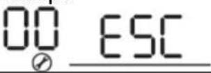 |
| 01 | Output source priority: To configure load power source priority | 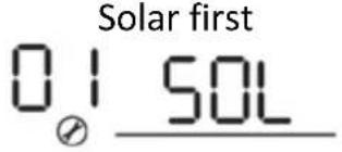 | Solar energy provides power to the loads as first priority. If solar energy is not sufficient to power all connected loads, battery energy will supply power the loads at the same time. Utility provides power to the loads only when any one condition happens: - Solar energy is not available - Battery voltage drops to low-level warning voltage or the setting point in program 12. |
 | Utility will provide power to the loads as first priority. Solar and battery energy will provide power to the loads only when utility power is not available. | ||
 | Solar energy provides power to the loads as first priority. If solar energy is not sufficient to power all connected loads, battery energy will supply power to the loads at the same time. Utility provides power to the loads only when battery voltage drops to either low-level warning voltage or the setting point in program 12. | ||
| 02 | Maximum charging | 10A (only available for chosen model) | 20A |
| current:To configure total charging current for solar and utility chargers.(Max. charging current = utility charging current + solar charging current) |  | ||
| 30A | 40A | ||
 | |||
50A (default) | |||
| 60A (only chosen model) | 70A (only chosen model) | ||
 | |||
| 80A (only chosen model) | 90A (only chosen model) | ||
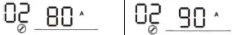 | |||
100A (only chosen 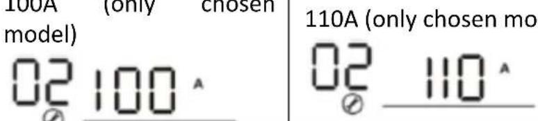 del) del) | |||
| 03 | AC input voltage range |  AC II AC II | |
| LIPS | if disabled, no matter a AC II | ||
| 04 | Power saving mode enable/disable | If disabled, no matter a  or of t be effected. or of t be effected. | |
 of en ty of en ty | |||
| 05 Battery type | ACM (default) | FI-1-1 | |
 | |||
| User-defined (only | If “user-defined” is | ||
available for chosen model)  | selected, battery charge voltage and low DC cut-off voltage can be set up in program 26, 27 and 29. | ||
| 06 | Auto restart when overload occurs | Restart disable (default)  | Restart enable  |
| 07 | Auto restart when over temperature occurs | Restart disable (default)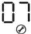  | Restart enable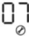  |
| 09 | Output frequency | 50Hz (default)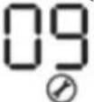 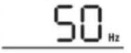 | 60Hz  Hz Hz |
| 11 | Maximum utility charging currentNote: if setting value in program 02 is smaller than that in program 11, the inverter will apply charging current from program 02 for utility charger. | Available options in 1000VA model : | |
10A  | 20A (default)  | ||
| Available options in 2000VA model : | |||
20A[T7SZ]  | 30A[S343]  | ||
| Available options in 5000VA model: | |||
2A  | 10A  | ||
20A  | 30A (default)  | ||
40A  | 50A  | ||
60A  | |||
| 12 | Setting voltage point back to utility source when selecting “SBU priority” or “Solar first” in program 01. | Available options in 1000VA/2000VA model: | |
22.0V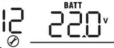 | 22.5V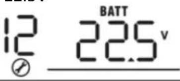 | ||
23.0V (default)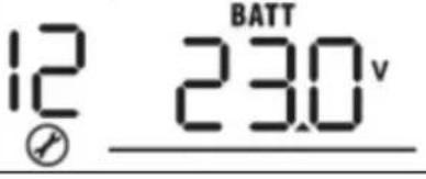 | 23.5V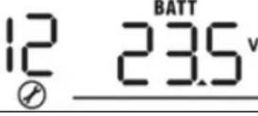 | ||
| 24.0VDCX3] | 24.5V | ||
25V | 25.5V | ||
| Available options in 5000KV model: | |||
44V | 45V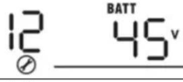 | ||
46V (default) | 47V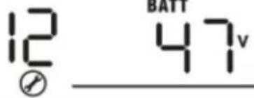 | ||
48V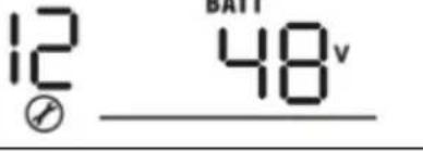 | 49V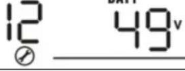 | ||
50V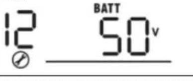 | 51V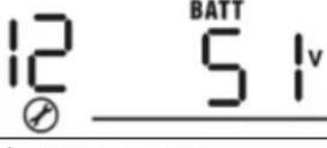 | ||
| 13 | Setting voltage point | Available options in 1000VA/2000VA model: | |
| Battery fully charged | 24V | ||
EN
| back to battery mode when selecting “SBU priority” or “Solar first” in program 01. | 24.5V | 25V |
| 25.5V | 26V | |
| 26.5V | 27V (default) | |
| 27.5V | 28V | |
| 28.5V | 29V | |
| Available options in 5000KV model: | ||
| Battery fully charged: | 48V | |
| 49V | 50V | |
| 51V | 52V | |
| 53V | 54V (default) | |
EN
| 55V | 56V |
| 57V | 58V |
If this inverter/charger is working in Line, Standby or Fault mode, charger source can be programmed as below:
Solar first: Solar energy will charge battery as first priority. Utility will charge battery only when solar energy is not available.
Utility first: Utility will charge battery as first priority. Solar energy will charge battery only when utility power is not available.
16 To configure charger source priority
Solar and utility (only available for 4000KV model)
Solar energy and utility will charge battery at the same time.
Only solar Solar energy will be the only charger source no matter utility is available or not.
If this inverter/charger is working in Battery mode or Power saving mode, only solar energy can charge battery. Solar energy will charge battery if it is available and sufficient.
18 Alarm control
Alarm on (default) Alarm off
 |  | ||
| 19 | Auto return to default display screen | Return to default display screen (default) | If selected, no matter how user switch display screen, it will automatically return to default display screen (Input voltage/output voltage) after no button is pressed for 1 minute. |
Stav at latest screen | If selected, the display screen will stay at latest screen user finally switches. | ||
| 20 | Backlight control | Backlight on (default) | Backlight off |
| 22 | Beeps while primary source is interrupted | Alarm on (default) | Alarm off |
| 23 | Overload bypass:When enabled, the unit will transfer to line mode if overload occurs in battery mode. | Bypass disable (default) | Bypass enable |
| 25 | Record fault mode | Record enable | Record disable (default) |
| 26 | Bulk charging voltage (C.V. Voltage) | 1000VA/2000VA default setting: 28.2V | |
| 4000VA default setting: 56.4V | |||
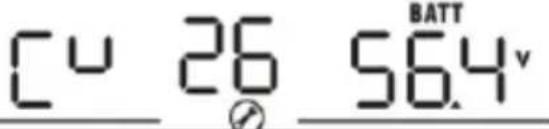 | |||
| If self-defined is selected in program 5, this program can be set up. Setting range is from 24.0V to 29.2V for 1000VA/2000VA model and 48.0V to 58.4V for 4000VA model. Increment of each click is 0.1V. | |||
| 27 | Floating charging voltage | 1000VA/2000VA default setting: 27.0V | |
4000VA default setting: 54.0V | |||
| If self-defined is selected in program 5, this program can be set up. Setting range is from 24.0V to 29.2V for 1000VA/2000VA model and 48.0V to 58.4V for 4000VA model. Increment of each click is 0.1V. | |||
| 29 | Low DC cut-off voltage | 1000VA/2000VA default setting: 21.0V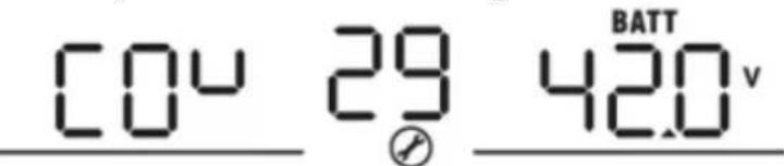 | |
4000VA default setting: 42.0V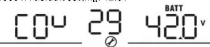 | |||
| If self-defined is selected in program 5, this program can be set up. Setting range is from 20.0V to 24.0V for 1000VA/2000VA model and 40.0V to 48.0V for 4000VA model. Increment of each click is 0.1V. Low DC cut-off voltage will be fixed to setting value no matter what percentage of load is connected. | |||
| 31 | Solar power balance:When enabled, solar input power will be automatically | Solar power balance:Enable (default) | If selected, solar input power will be automatically adjusted according to the following formula:Max. input solar power = Max. battery charging |
EN
| adjusted according to connected load power (only available in 4000VA model) | Solar power balance disable: | power + connected load power.If selected, the solar input power will be the same to max. battery charging power no matter how much loads are connected. The max.battery charging power will be based on the setting current in program 02.(Max. solar power = Max. battery charging power) | |
| 33 | Battery equalization | If “flooded” or “User-defined” is selected in program 05, this program can be set up.1000VA/2000VA default setting: 29.2V | |
| 34 | Battery equalization voltage | Setting range is from 25.0V to 30V. Increment of each click is 0.1V.4000VA default setting: 58.4V | |
| 35 | Battery equalized time | Setting range is from 50V to 60V. Increment of each click is 0.1V.60 min (default) | Setting range is from 5 min to 900 min.Increment of each click is 5 min. |
| 36 | Battery equalized timeout | 120 min (default) | Setting range is from 5 min to 900 min.Increment of each click is 5 min. |
| 37 | Equalization interval | 30 days (default) | Setting range is from 0 to 90 days.Increment of each click is1 day. |
| 39 | Equalization activated immediately | Enable | Disable (default)[IMAGE] |
If equalization function is enabled in program 30, this program can be set up. If “enable” is selected in this program, it is to activate battery equalization immediately and display main page will show .TI“disable” is selected, it will cancel equalization function until next activated equalization time arrivesbased on program 35 setting. At this timewill not be shown in display main page. immediately and display main page will show .TI“disable” is selected, it will cancel equalization function until next activated equalization time arrivesbased on program 35 setting. At this timewill not be shown in display main page. | |||
DISPLAY SETTING
The LCD display information will be switched in turns by pressing "UP" or "DOWN" button. The selectable information is switched as below order: input voltage, input frequency, PV voltage, charging current, battery voltage, output voltage, output frequency load percentage, load in VA, load in Watt, DC discharging current, main CPU version and second CPU version.
| Selectable information | LCD display |
| Input voltage/Output voltage (default display screen) | Input voltage=230V, output voltage=230V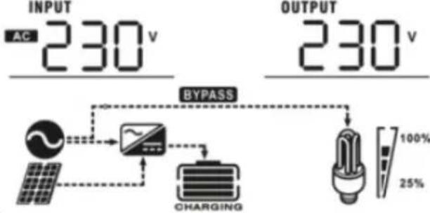 |
| Input frequency | Input frequency=50Hz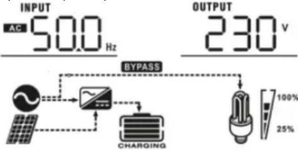 |
| PV voltage | PV voltage=60V |
EN
Charging current=50A
Charging current
Battery voltage = 25.5V, discharging current = 1A
Battery voltage/ DC discharging current
Output frequency = 50Hz
Output frequency
Load percent = 70%
Load percentage
Load in VA
When connected load is lower than 1kVA, load in VA will present "xxxVA" like shown
below: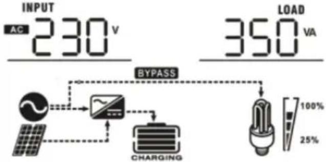 When load is larger than 1kVA (≥1kVA), load in VA will present “x.xkVA” like shown below: When load is larger than 1kVA (≥1kVA), load in VA will present “x.xkVA” like shown below: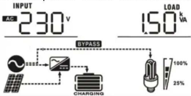 | |
| Load in Watt | When load is lower than 1kW, load in W will present “xxxW” like shown below: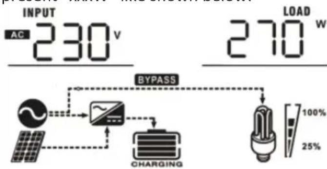 When load is larger than 1kW (≥1kW), load in W will present “x.xkW” like shown below: When load is larger than 1kW (≥1kW), load in W will present “x.xkW” like shown below: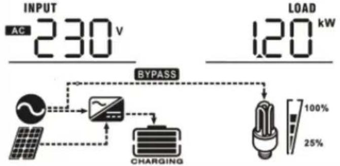 |
EN
Main CPU version 00014.04
Main CPU version checking
OPERATING MODE DESCRIPTION
| Mode | Description | Displayed |
| Standby mode/Power saving modeNote: Standby mode – the inverter is not turned on yet but at this time, the inverter can charge battery without AC output.Power saving mode – if enabled, the output of inverter will be off when connected load is pretty low or not detected. | No output is supplied by the unit but it still can charge batteries. | Charging by utility:Charging by PV energy: |
| Fault modeNote: Fault mode – errors caused by inside circuit error or external reasons such as over | PV energy and utility can charge batteries. | Charging by utility and PV energy (only available in - 1000VA/2000VA): |
| Charging by utility (only available in only available in - 1000VA/2000VA): | ||
| temperature, output short circuited and so on. | 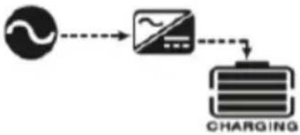 | |
Chargin by PV energy: 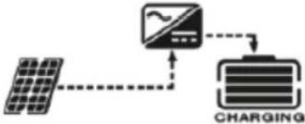 | ||
No charging:  | ||
| Utility can power loads when the unit starts up without battery (only available in 4000VA models with single operation). | Power from utility: 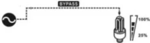 | |
| Line mode | The unit will provide output power from the mains. It will also charge the battery at line mode. | Charging by utility and PV energy: 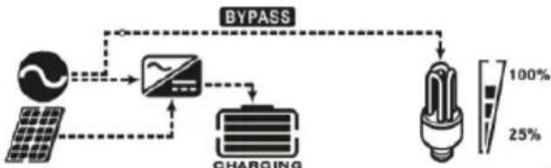 |
Charging by utility: 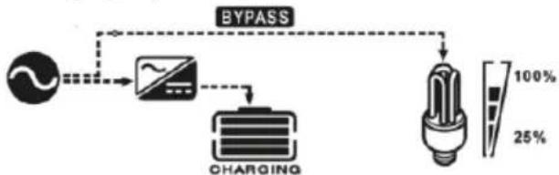 | ||
| Battery mode | The unit will provide output power from the battery and PV power. | Power from battery and PV energy:  |
| Power from battery only: |
 |
BATTERY EQUALIZATION DESCRIPTION
Equalization function is added into charge controller. It reverses the buildup of negative chemical effects like stratification, a condition where acid concentration is greater at the bottom of the battery than at the top. Equalization also helps to remove sulfate crystals that might have built up on plates. If left unchecked, this condition, called sulfation, will reduce the overall capacity of the battery. Therefore, it's recommended to equalize battery periodically.
- Applying the equalization function:
Battery equalization function in monitoring LCD setting program 30 must be enabled first. Than this function in device must be applied by either one of following methods:
a) Setting equalization interval in program 35.
b) Active equalization immediately in program 36.
- When to equalize?
In float stage, when the setting equalization interval (battery equalization cycle) is arrived, or equalization is active immediately, the controller will start to enter Equalize stage.
line
| x | y | |---|---| | 1 | b | | 2 | a | | 3 | b | | 4 | a | | 3 | b |a) Equalize voltage
b) Float voltage
- Bulk
- Absorption
- Float
- Equalize
- Equalize charging time and timeout
In Equalize stage, the controller will supply power to charge battery as much as possible until battery voltage raises to battery equalization voltage. Then, constant-voltage regulation is applied to maintain battery voltage at the battery equalization voltage. The battery will remain in the Equalize stage until setting battery equalized time is arrived.
area
| Stage | Value | |-------|-------| | 1 | a | | 2 | c | | 3 | b | | 4 | d |a) Equalize voltage
b) Float voltage
c) Absorption voltage
d) Equalize charging time
- Bulk
- Absorption
- Float
- Equalize
However, in equalize stage, when battery equalized time is expired and battery voltage doesn't rise to battery equalization voltage point, the charger controller will extend the battery equalized time until battery voltage achieves battery equalization voltage. If battery voltage is still lower than battery equalization voltage when battery equalized time setting is over, the charge controller will stop equalization and return to float stage.
area
| Stage | Value | |-------|-------| | 1 | a | | 2 | b | | 3 | b | | 4 | b |a) Equalize voltage
b) Float voltage
c) Absorption voltage
e) Equalize charging timeout
- Bulk
- Absorption
- Float
- Equalize
FAULT REFERENCE CODES
| Fault code | Meaning | Displayed icon | |
| 01 | Fan is locked when inverter is off. |  | |
| 02 Excessive temperature. |  | ||
| 03 | Battery voltage is too high. |  | |
| 04 Battery voltage is too low |  | ||
| 05 | Output short circuited or excessive temperature is detected by internal converter components. |  | |
| 06 | Output voltage is abnormal (for |  | |
| 1000VA/2000VA models). | |||
| Output voltage is too high (for 4000VA model). | |||
| 07 Overload time out. | 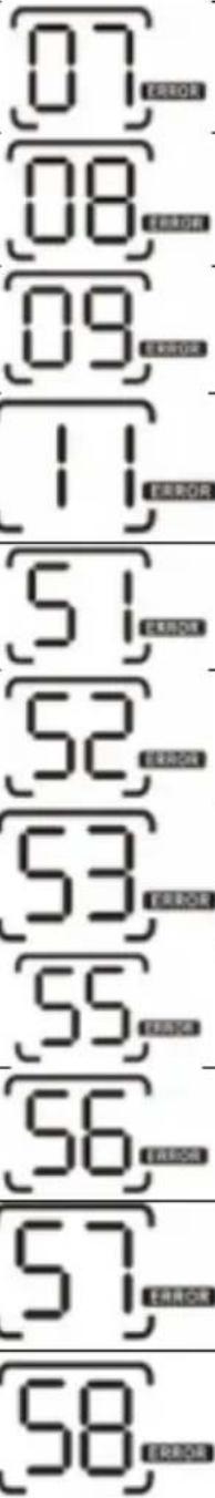 | ||
| 08 Bus voltage is too high. | |||
| 09 Bus soft start failed. | |||
| 11 Main relay failed. | |||
| 51 Overcurrent or surge. | |||
| 52 Bus voltage is too low. | |||
| 53 Inverter soft start failed. | |||
| 55 | Over DC voltage in AC output. | ||
| 56 | Battery connection is open. | ||
| 57 Current sensor failed. | |||
| 58 Output voltage is too low. | |||
| Note: fault codes 51, 52, 53, 55, 56, 57 and 58 are available only in 4000VA model. | |||
WARNING INDICATOR
| Warning code | Meaning | Audible alarm | Icon flashing |
| 01 | Fan is locked when inverter is on. | Beep three times every second. | 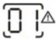 | ||
| 03 | Battery is over-charged. | Beep once every second | 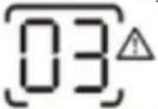 | ||
| 04 Low battery. | Beep once every second. | 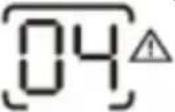 | |||
| 07 Overload. | Beep once every 0.5 second. |   | |||
| 10 | Output power derating | Beep twice every 3 seconds | 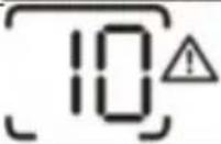 |
APPROXIMATE BACK-UP TIME TABLE
| Model | Load (VA) | Backup time @ 24VDC 100Ah (min) | Backup time @ 24VDC 200Ah (min) |
| 1000VA | 100 | 766 | 1610 |
| 200 | 335 | 766 | |
| 300 | 198 | 503 | |
| 400 | 139 | 339 | |
| 500 | 112 | 269 | |
| 600 | 95 | 227 | |
| 700 | 81 | 176 | |
| 800 | 62 | 140 | |
| 900 | 55 | 125 | |
| 1000 | 50 | 112 | |
| 2000VA | 200 | 766 | 1610 |
| 400 | 335 | 766 | |
| 600 | 198 | 503 | |
| 800 | 139 | 339 | |
| 1000 | 112 | 269 | |
| 1200 | 95 | 227 | |
| 1400 | 81 | 176 | |
| 1600 | 62 | 140 | |
| 1800 | 55 | 125 | |
| 2000 | 50 | 112 | |
| Model | Load (VA) | Backup time @ | Backup time @ |
| 48VDC 100Ah (min) | 48VDC 200Ah (min) | ||
| 5000VA | 500 | 618 | 1288 |
| 1000 | 268 | 613 | |
| 1500 | 158 | 402 | |
| 2000 | 111 | 271 | |
| 2500 | 90 | 215 | |
| 3000 | 76 | 182 | |
| 3500 | 65 | 141 | |
| 4000 | 50 | 112 | |
| 4500 | 44 | 100 | |
| 5000 | 40 | 90 |
3.4. Cleaning and maintenance
a) Unplug the mains plug and allow the device to cool completely before each replacement of accessories, or if the device is not being used.
- Wait for the rotating elements to stop.
b) Use only non-corrosive cleaners to clean the surface.
c) Store the unit in a dry, cool place, free from moisture and direct exposure to sunlight.
d) Do not spray the device with a water jet or submerge it in water.
e) Do not allow water to get inside the device through vents in the housing of the device.
f) Clean the vents with a brush and compressed air.
g) The device must be regularly inspected to check its technical efficiency and spot any damage.
h) Use a soft cloth for cleaning.
i) Do not use sharp and/or metal objects for cleaning (e.g. a wire brush or a metal spatula) because they may damage the surface material of the appliance.
j) Do not clean the device with an acidic substance, agents of medical purposes, thinners, fuel, oils or other chemical substances because it may damage the device.
DISPOSING OF USED DEVICES
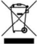
Do not dispose of this device in municipal waste systems. Hand it over to an electric and electrical device recycling and collection point. Check the symbol on the product, instruction manual and packaging. The plastics used to construct the
device can be recycled in accordance with their markings. By choosing to recycle you are making a significant contribution to the protection of our environment.
Contact local authorities for information on your local recycling facility.
TROUBLESHOOTING
| Problem | LCD/LED/Buzer | Possible cause | Solution |
| Unit shuts down automatically during startup process. | LCD/LEDs and buzzer will be active for 3 seconds and then complete off | The battery voltage is too low (<1.91V/cell). | 1. Recharge batter.2. Replace battery. |
| No response after power on. | No indication | 1. The battery voltage is far too low (<1.4V/cell).2. Battery polarity is connected reversed. | 1. Check if batteries and the wiring are connected well.2. Recharge battery.3. Replace battery. |
| Mains exist but the unit works in battery mode. | Input voltage is displayed as 0 on the LCD and green LED is flashing. | Input protector is tripped. | Check if Ac breaker is tripped and AC wiring is connected well. |
| Green LED is flashing. | Insufficient quality of AC power (shore or generator). | 1. Check if AC wires are too thin and/or too long.2. Check if generator (if applied) is working well or if input voltage range setting is correct (UPS→Appliance). | |
| Green LED is flashing. | Set “Solar first” as the priority of output source. | Change output source priority to Utility first. | |
| When the unit is turned on, internal relay is switched onand off repeatedly. | LCD display and LEDs are flashing. | Battery is disconnected. | Check if battery wires are connected well. |
| Buzzer beeps continuously and red LED is on. | Fault code 07 | Overload error.The inverter is overloaded 110% and time is up. | Reduce the connected load by switching off some equipment. |
| Fault code 05 | Output short circuited. | Check if wiring is connected well and remove abnormal load. | |
| Temperature of internal converter component is over 120°C (only available for 1000VA/2000VA models) | Check whether the air flow of the unit is blocked or whether the ambient temperature is high. | ||
| Fault code 02 | Internal temperature of inverter component is over 100°C. | ||
| Fault code 03 | Battery is overcharged. | Return for service repair. | |
| The battery voltage is too high. | Check if spec and quantity of batteries are meet requirements. | ||
| Fault code 01 | Fan fault. | Replace the fan. | |
| Fault code 06/58 | Output abnormal (inverter voltage below 190VAC or higher than 260VAC). | 1. Reduce the connected load.2. Return for service repair. | |
| Fault code 08/09/53/57 | Internal component failed. | Return to service repair. | |
| Fault code 51 | Overcurrent or surge. | Restart the unit, if the error happens again, please return for service repair. | |
| Fault code 52 | Bus voltage is too low. | ||
| Fault code 55 | Output voltage isunbalanced. | ||
| Fault code 56 | Battery is not connected well or fuse is burnt. | If the battery is connected well, please return for service repair. |

natural_image
Technical line drawing of an internal computer drive showing fan, drive, and cable ports (no text or labels)natural_image
Diagram of an electronic device casing with labeled ports and internal components, showing no text or symbols.PODŁĄCZENIE AKUMULATORA
natural_image
Technical line drawings of an electrical enclosure with internal components and mounting base (no text or symbols)POŁĄCZENIE KOMUNIKACYJNE
Solar Monitor System

Help

SYGNAŁ SUCHY
natural_image
Technical line drawing of a computer drive showing internal components and external ports (no text or symbols)natural_image
Technical line drawing of an industrial control unit with labeled ports and internal components (no text or symbols)PŘIPOJENÍ BATERIE
Solar Monitor System

Welcome!
Help


SUCHÝ KONTAKTNÍ SIGNÁL
natural_image
Technical line drawing of a computer drive showing internal components and external ports (no text or labels)natural_image
Diagram of an electronic device casing with labeled ports and internal components, showing no text or symbols.CONNEXION DE LA BATTERIE
natural_image
Technical line drawing of an electrical enclosure showing main panel, circuit breakers, and fan (no text or symbols)2000-5000VA :
natural_image
Technical line drawings of an electrical control unit with internal components and mounting base (no text or symbols)CONNEXION DE COMMUNICATION
natural_image
Technical line drawing of a computer drive showing internal components and external ports (no text or labels)natural_image
Diagram of an industrial control panel with labeled ports and arrows indicating orientation (no text or symbols present)natural_image
Technical line drawing of an electronic device interior showing labeled terminals and a fan (no text or symbols beyond basic labels)2000-5000VA:

Solar Monitor System

Welcome!
Help


Please enter user name
Please enter password
Authentication code
Remember me
Sign In
iOS
SEGNALE DI CONTATTO SECCO
23,0 V (predefinito)
23.5V
12
natural_image
Technical line drawing of a computer drive showing internal components and external ports (no text or symbols)natural_image
Diagram of an electronic device casing with labeled ports and internal components, showing no text or symbols.Solar Monitor System

Welcome!
Help


natural_image
Technical line drawing of a computer drive showing internal components and external ports (no text or symbols)natural_image
Diagram of an industrial control panel with labeled ports and arrows indicating orientation (no text or symbols present)AKKUMULÁTOR CSATLAKOZTATÁSA
natural_image
Technical line drawings of an electrical control unit with internal components and mounting base (no text or symbols)KOMMUNIKÁCIÓS KAPCSOLAT
Solar Monitor System

Welcome!
Help


SZÁRAZON ÉRINTKEZŐ JEL
APPARATETS PLACERING
natural_image
Technical line drawing of a computer drive showing internal components and external ports (no text or symbols)natural_image
Diagram of an industrial control panel with labeled ports and arrows indicating orientation (no text or symbols present)BATTERIFORBINDELSE
natural_image
Technical line drawing of an electrical enclosure showing main panel, circuit breakers, and fan (no text or symbols)2000-5000VA:

Solar Monitor System Welcome! Help


SIGNAL FRA T∅R KONTAKT
natural_image
Technical line drawing of a computer drive showing internal components and external ports (no text or symbols)natural_image
Diagram of an industrial control panel with labeled ports and arrows indicating orientation (no text or symbols present)AKUN LIITÄNTÄ
Solar Monitor System

Welcome!
Help


KUIVA KOSKETUS SIGNAALI
PLAATS VAN HET APPARAAT
natural_image
Technical line drawing of a computer power supply unit showing internal components and external casing (no text or labels)natural_image
Diagram of an electronic device casing with labeled ports and internal components, showing no text or symbols.ACCU-AANSLUITING
natural_image
Technical line drawing of an electronic device interior showing labeled terminals (IN, OUT) and a fan blade (no text or symbols beyond labels)2000-5000VA:

Solar Monitor System

Welcome!
Help


DROOG CONTACTSIGNAAL
WEERGAVEPICTOGRAMMEN
flowchart
graph TD
    A["INPUTBATTTEMP AC PV 8.8.8 kW VA % Hz"] --> B["BYPASS"]
    C["OUTPUTBATTLOAD 8.8.8 kW VA % Hz"] --> D["CHARGING"]
    B --> E["OVER LOAD 100% 25%"]
    D --> E
    E --> F["Charging"]
    F --> G["Power Supply"]
    style A fill:#f9f,stroke:#333
    style C fill:#f9f,stroke:#333
    style B fill:#ccf,stroke:#333
    style D fill:#ccf,stroke:#333
    style E fill:#fff,stroke:#333
WAARSCHUWING INDICATOR
natural_image
Technical line drawing of a computer drive showing internal components and external ports (no text or symbols)natural_image
Diagram of an industrial control panel with labeled ports and arrows indicating orientation (no text or symbols present)BATTERILKOBLING
natural_image
Technical line drawing of an electrical switchgear cabinet with labeled terminals (IN, OUT) and fan components (no text or symbols beyond labels)2000-5000VA:

KOMMUNIKASJONSKOBLING
Solar Monitor System

Welcome!
Help


T∅RR KONTAKTSIGNAL
Stille inn programmer:
APPARATENS PLACERING
natural_image
Technical line drawing of a computer drive showing internal components and external ports (no text or symbols)natural_image
Technical line drawing of a server rack with control panel and drive unit (no text or symbols)BATTERIANSLUTNING
natural_image
Technical line drawing of an electrical switchgear cabinet with labeled terminals (IN, OUT) and a fan blade (no text or symbols beyond labels)2000-5000VA:

Solar Monitor System

Welcome!
Help


TORR KONTAKTSIGNAL
natural_image
Technical line drawing of a computer drive showing internal components and external ports (no text or labels)natural_image
Diagram of an industrial control panel with labeled ports and arrows indicating orientation (no text or symbols present)CONEXÃO DA BATERIA
natural_image
Technical line drawings of an electrical enclosure with internal components and mounting base (no text or symbols)SINAL DE CONTATO SECO
natural_image
Technical line drawing of a computer drive showing internal components and external ports (no text or symbols)natural_image
Diagram of an industrial control unit with labeled ports and internal components, showing no text or symbols.PRIPOJENIE NA BATÉRIU
natural_image
Technical line drawing of an electrical switchgear cabinet with labeled terminals (IN, OUT) and fan components (no text or symbols beyond labels)2000-5000VA:
Solar Monitor System

Welcome!
Help


SUCHÝ KONTAKTNÝ SIGNÁL
For the disposal of the device please consider and act according to the national and local rules and regulations.
CONTACT
expondo Polska sp. z o.o. sp. k.