GCL 12V-50-22 CG Professional - Measuring equipment BOSCH - Free user manual and instructions
Find the device manual for free GCL 12V-50-22 CG Professional BOSCH in PDF.

| Product type | Laser points and lines, laser class 2 |
| Brand | Bosch |
| Model | GCL 12V-50-22 CG Professional |
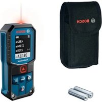
| Laser line range (standard) | 25 m |
| Laser point range | 10 m |
| Leveling accuracy (lines) | ±0.3 mm/m |
| Leveling accuracy (points) | ±0.7 mm/m |
| Self-leveling range | ±4° |
| Leveling time | < 4 s |
| Power supply | 12 V Lithium-Ion battery (recommended GBA 12V...) or alkaline batteries 4 × 1.5 V LR6 (AA) via adapter |
| Battery life (points and cross lines mode) | 8 h (Li-Ion battery), 4 h (alkaline batteries) |
| Dimensions (L × W × H) | 152 × 68 × 116 mm |
| Weight (without battery/adapter) | 0.59 kg |
| Protection rating | IP65 |
| Radio interface | Bluetooth® 5.2 (Low Energy), range max. 30 m |
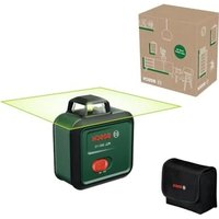
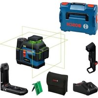
| Operating modes | Points and cross lines, horizontal line, vertical line, points |
| Tilt function | Yes, automatic switching when outside self-leveling range |
| Automatic shut-off | After 120 min (can be deactivated) |
| Operating temperature | −10 °C to +45 °C |
| Tripod mount | 1/4" |
| Remote control | Via Bosch Levelling Remote App (smartphone) |
| Cleaning and maintenance | Soft, damp cloth, without detergents or solvents |
| Repairability | Bosch after-sales service, spare parts at www.bosch-pt.com |
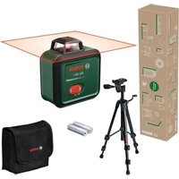
| Delivery content | Measuring device, battery (depending on version), battery adapter, protective case, optional accessories (swivel mount, tripod, etc.) |
Frequently Asked Questions - GCL 12V-50-22 CG Professional BOSCH
User questions about GCL 12V-50-22 CG Professional BOSCH
0 question about this device. Answer the ones you know or ask your own.
Ask a new question about this device
Download the instructions for your Measuring equipment in PDF format for free! Find your manual GCL 12V-50-22 CG Professional - BOSCH and take your electronic device back in hand. On this page are published all the documents necessary for the use of your device. GCL 12V-50-22 CG Professional by BOSCH.
USER MANUAL GCL 12V-50-22 CG Professional BOSCH
GCL 12V-50-22 CG Professional
Robert Bosch Power Tools GmbH
70538 Stuttgart
GERMANY
www.bosch-pt.com
1609 92A 9B1 (2024.09) T/717

natural_image
3D rendered mechanical device with no visible text or symbols1 609 92A 9B1 | (14.08.2024) Bosch Power Tools
Bosch Power Tools 1 609 92A 9B1 | (14.08.2024)
6
A

1 609 92A 9B1 | (14.08.2024) Bosch Power Tools
Bosch Power Tools 1 609 92A 9B1 | (14.08.2024)
1 609 92A 9B1 | (14.08.2024) Bosch Power Tools
Bosch Power Tools 1 609 92A 9B1 | (14.08.2024)
(18)
RM 20
1 600 A03 1YN
(22)
BM 1
0 601 015 A01
(23)
LB 10
natural_image
Exterior view of a mechanical device with mounting flanges and a central handle (no text or symbols visible)(21)
DK 20
1 608 M00 C4C

(24)

(25)
1 608 M00 05J
(26)
LR 7
0 601 069 J00
0 601 096 B00
(29)
AA 1
1 608 M00 C1B
natural_image
Simple line drawing of a rectangular device with a label on the top (no text or symbols present)(30)
natural_image
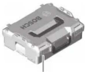
3D rendered image of a metallic electronic component with no visible text or symbols(31) L-BOXX 136 1 600 A01 2G0
Deutsch
Sicherheitshinweise

www.bosch-pt.com/serviceaddresses
Transport
All instructions must be read and observed in order for the measuring tool to function safely. The safeguards integrated into the measuring tool may be compromised if the measuring tool is not used in accordance with these instructions. Never make warning signs on the measuring tool unrecognisable. SAVE THESE IN-
STRUCTIONS FOR FUTURE REFERENCE AND INCLUDE THEM WITH THE MEASURING TOOL WHEN TRANSFERRING IT TO A THIRD PARTY.
u Warning! If operating or adjustment devices other than those specified here are used or other procedures are carried out, this can lead to dangerous exposure to radiation.
u The measuring tool is delivered with a laser warning sign (marked in the illustration of the measuring tool on the graphics page).
u If the text of the laser warning label is not in your national language, stick the provided warning label in your national language over it before operating for the first time.
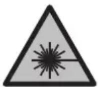
Do not direct the laser beam at persons or animals and do not stare into the direct or reflected laser beam yourself. You could blind somebody, cause accidents or damage your eyes.
u If laser radiation hits your eye, you must close your eyes and immediately turn your head away from the beam.
u Do not make any modifications to the laser equipment.
Do not use the laser goggles (accessory) as protective goggles. The laser goggles make the laser beam easier to see; they do not protect you against laser radiation.
Do not use the laser goggles (accessory) as sunglasses or while driving. The laser goggles do not provide full UV protection and impair your ability to see colours.
u Have the measuring tool repaired only by a qualified specialist using only original replacement parts. This will ensure that the safety of the measuring tool is maintained.
Do not let children use the laser measuring tool unsupervised. They could unintentionally blind themselves or other persons.
▶ Do not use the measuring tool in explosive atmospheres which contain flammable liquids, gases or dust. Sparks may be produced inside the measuring tool, which can ignite dust or fumes.
▶ Do not modify or open the battery. There is a risk of short-circuiting.
In case of damage and improper use of the battery, vapours may be emitted. The battery can set alight or explode. Ensure the area is well ventilated and seek medical attention should you experience any adverse effects. The vapours may irritate the respiratory system.
If used incorrectly or if the battery is damaged, flammable liquid may be ejected from the battery. Contact with this liquid should be avoided. If contact accidentally occurs, rinse off with water. If the liquid comes into contact with your eyes, seek additional medical attention. Liquid ejected from the battery may cause irritation or burns.
The battery can be damaged by pointed objects such as nails or screwdrivers or by force applied externally. An internal short circuit may occur, causing the battery to burn, smoke, explode or overheat.
When the battery is not in use, keep it away from paper clips, coins, keys, nails, screws or other small metal objects that could make a connection from one terminal to another. A short circuit between the battery terminals may cause burns or a fire.
▶ Only use the battery with products from the manufacturer. This is the only way in which you can protect the battery against dangerous overload.
▶ Only charge the batteries using chargers recommended by the manufacturer. A charger that is suitable for one type of battery may pose a fire risk when used with a different battery.

Protect the battery against heat, e.g. against continuous intense sunlight, fire, dirt, water and moisture. There is a risk of explosion and short-circuiting.
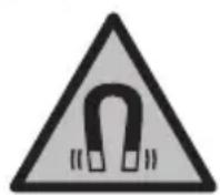
Keep the magnetic accessories away from implants and other medical devices, e.g. pacemakers or insulin pumps. The magnets in the accessories generate a field that can impair the function of implants and medical devices.
- Keep the magnetic accessories away from magnetic data storage media and magnetically-sensitive devices. The effect of the magnets in the accessories can lead to irreversible data loss.
36 | English
The measuring tool is equipped with a wireless interface. Local operating restrictions, e.g. in aeroplanes or hospitals, must be observed.
The Bluetooth ^® word mark and logos are registered trademarks owned by Bluetooth SIG, Inc. and any use of such marks by Robert Bosch Power Tools GmbH is under license.
▶ Caution! When using the measuring tool with Bluetooth ^® , a fault may occur in other devices and systems, aeroplanes and medical devices (e.g. pacemakers, hearing aids). Also, damage to people and animals in the immediate vicinity cannot be completely excluded. Do not use the measuring tool with Bluetooth ^® in the vicinity of medical devices, petrol stations, chemical plants, areas with a potentially explosive atmosphere and in blasting areas. Do not use the measuring tool with Bluetooth ^® on aeroplanes. Avoid using the product near your body for extended periods.
Product Description and Specifications
Please observe the illustrations at the beginning of this operating manual.
Intended Use
The measuring tool is intended for determining and checking horizontal and vertical lines and plumb points.
The measuring tool is suitable for indoor and outdoor use.
This product is a consumer laser product in accordance with EN 50689.
Product Features
The numbering of the product features shown refers to the illustration of the measuring tool on the graphic page.
(1) Charge-control indicator rechargeable batteries/non-rechargeable batteries
(2) Bluetooth® button
(3) Button for laser operating mode
(4) On/off switch
(5) Laser beam outlet aperture
(6) 1/4" tripod mount
(7) Guide groove
(8) Laser warning label
(9) Serial number
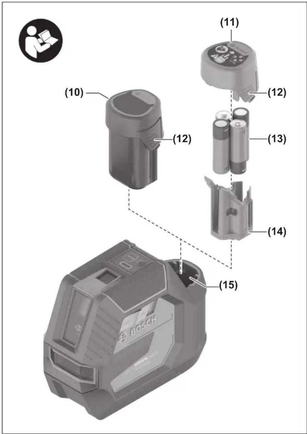
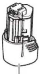
(10) Rechargeable battery ^4
(11) Battery adapter cap
(12) Rechargeable battery/battery adapter release button
(13) Batteries ^a)
(14) Battery adapter cover
(15) Battery bay
(16) Fastening slot ^4
(17) Guide rail
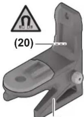
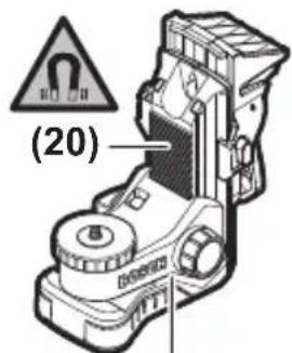
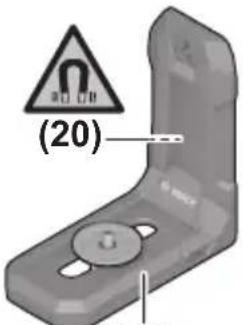
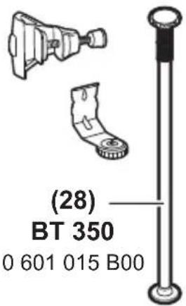
(18) Rotating mount (RM 20)
(19) Fine adjustment screw of the rotating mount
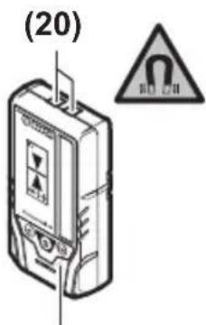
(20) Magnet ^1
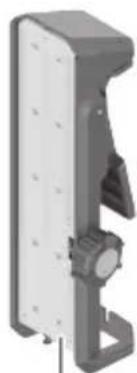
(21) Ceiling clip (DK 20)
(22) Universal holder ^a)
(23) Holder (LB 10)
(24) Laser target plate ^a)
(25) Laser viewing glasses ^a)
(26) Laser receiver ^a)
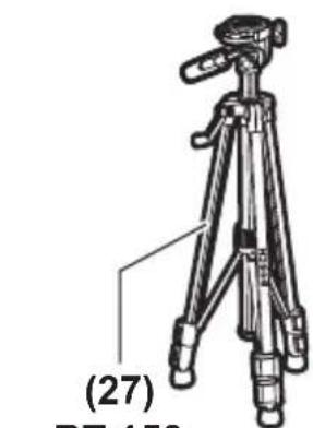
(27) Tripod ^1
(28) Telescopic rod ^4
(29) Battery adapter
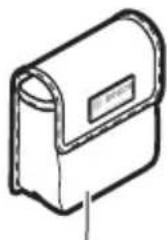
(30) Protective bag ^4
(31) Case ^a)
a) This accessory is not part of the standard scope of delivery.
Technical Data
| Point and line laser GCL 12V-50-22 CG | ||
| Article number | 3 601 K66 S.. | |
| Working range ^A) | ||
| – Standard laser lines 25 m | ||
| – Laser lines with laser receiver 5–50 m | ||
| – Laser points 10 m | ||
Bosch Power Tools 1 609 92A 9B1 | (14.08.2024)
38 | English
Point and line laser GCL 12V-50-22 CG
| Levelling accuracyB)C) | |
| – Laser lines ±0.3 mm/m | |
| – Laser points ±0.7 mm/m | |
| Self-levelling range ±4° | |
| Levelling time < 4 s | |
| Max. altitude 2000 m | |
| Relative air humidity max. 90 % | |
| Pollution degree according to IEC 61010-1 2 | D) |
| Laser class 2 | |
| Laser line | |
| – Laser type < 10 mW, 500–540 nm | |
| – C610 | |
| – Divergence 50 × 10 mrad (full angle) | |
| – Pulse frequency 10 kHz | |
| Laser point | |
| – Laser type < 1 mW, 500–540 nm | |
| – C61 | |
| – Divergence | 0.8 mrad (full angle) |
| – Pulse frequency | 1 kHz |
| Shortest pulse duration | 0.03 ms |
| Compatible laser receiver | LR 7 |
| Tripod mount | 1/4" |
| Energy supply | |
| – Lithium-ion battery | 12 V |
| – Alkaline manganese non-rechargeable batteries (with battery adapter) | 4 × 1.5 V LR6 (AA) |
| Operating time for cross-line and point operationE) | |
| – With lithium-ion battery | 8 h |
| – With alkaline manganese non-rechargeable bat-teries | 4 h |
English | 39
Point and line laser GCL 12V-50-22 CG
| Bluetooth® measuring tool | |
| - Compatibility Bluetooth® 5.2 (Low Energy) | F) |
| - Max. signal range 30 m | G) |
| - Operating frequency range 2402–2480 MHz | |
| - Max. transmission power 3.3 mW | |
| Bluetooth® smartphone | |
| - Compatibility Bluetooth® 5.2 (Low Energy) | F) |
| WeightH) | 0.59 kg |
| Dimensions (length × width × height) 152 × 68 × 116 mm | |
| Protection ratingI) | IP65 |
| Recommended ambient temperature during charging | 0 °C to +35 °C |
| Permitted ambient temperature during operation -10 °C to +45 °C | |
| Permitted ambient temperature during storage (without a rechargeable battery) | -20 °C to +70 °C |
| Recommended rechargeable batteries (2–3 Ah) | GBA 12V... |
40 | English
Point and line laser GCL 12V-50-22 CG
Recommended battery chargers GAL 12...
GAX 18...
A) The working range may be reduced by unfavourable environmental conditions (e.g. direct sunlight).
B) The values stated presuppose normal to favourable environmental conditions (e.g. no vibration, no fog, no smoke, no direct sunlight). Extreme fluctuations in temperature can cause deviations in accuracy.
C) An additional deviation of ±0.1 mm/m must be taken into account when at maximum self-leveling range.
D) Only non-conductive deposits occur, whereby occasional temporary conductivity caused by condensation is expected.
E) Shorter operating times when operated with Bluetooth®
F) When using Bluetooth® Low Energy devices, it may not be possible to establish a connection depending on the model and operating system. Bluetooth® devices must support the SPP profile.
G) The signal range may vary greatly depending on external conditions, including the receiving device used. The Bluetooth® range may be significantly weaker inside closed rooms and through metallic barriers (e.g. walls, shelving units, cases, etc.).
H) Weight without rechargeable batteries/battery adapter/non-rechargeable batteries
I) The lithium-ion battery pack and the battery adapter are excluded from the protection rating. The serial number (9) on the type plate is used to clearly identify your measuring tool.
Measuring Tool Power Supply
The measuring tool can be operated either with conventional non-rechargeable batteries or with a Bosch lithium-ion battery.
Operation with Non-Rechargeable Batteries
It is recommended that you use alkaline manganese batteries to operate the measuring tool.
The batteries are inserted into the battery adapter.
The battery adapter is intended only for use in designated Bosch measuring tools and must not be used with power tools.
To insert the batteries, slide the cover (14) of the battery adapter into the battery bay (15). Place the batteries into the cover as per the illustration on the sealing cap (11).
Slide the sealing cap over the cover until you feel it click into place.
To remove the batteries (13), press the release buttons (12) on the cap (11) and pull the cap off. Remove the batteries. To remove the cover (14) from inside the battery bay,
reach into the cover and pull it out of the measuring tool, applying light pressure to the side wall as you do so.
Always replace all the batteries at the same time. Only use batteries from the same manufacturer and which have the same capacity.
▶ Take the batteries out of the measuring tool when you are not using it for a prolonged period of time. The batteries can corrode during prolonged storage in the measuring tool.
Operation with Rechargeable Battery
▶ Use only the chargers listed in the technical data. Only these chargers are matched to the lithium-ion battery of your measuring tool.
Note: Lithium-ion rechargeable batteries are supplied partially charged according to international transport regulations. To ensure full rechargeable battery capacity, fully charge the rechargeable battery before using your tool for the first time.
To insert the charged battery (10), slide it into the battery bay (15) until you feel it engage.
To remove the battery (10), press the release buttons (12) and pull it out of the battery bay (15). Do not use force to do this.
Recommendations for Optimal Handling of the Battery
Protect the battery against moisture and water.
Only store the battery within a temperature range of -20 to 50 °C. Do not leave the battery in your car in the summer, for example.
A significantly reduced operating time after charging indicates that the battery has deteriorated and must be replaced.
Follow the instructions on correct disposal.
Battery Charge Indicator on the Measuring Tool
The battery charge indicator (1) shows the current state of charge of the rechargeable battery/non-rechargeable batteries when the measuring tool is switched on.
If the rechargeable battery or non-rechargeable batteries are running low, the laser lines will gradually become dimmer.
If the rechargeable battery/non-rechargeable batteries are almost empty, the battery charge indicator (1) will flash continuously. The laser lines will flash for 5 seconds every 5 minutes.
42 | English
If the rechargeable battery/non-rechargeable batteries are empty, the laser lines and the battery charge indicator (1) will flash one last time before the measuring tool switches off.
Operation
Starting Operation
▶ Protect the measuring tool from moisture and direct sunlight.
▶ Do not expose the measuring tool to any extreme temperatures or fluctuations in temperature. For example, do not leave it in a car for extended periods of time. If it has been subjected to significant fluctuations in temperature, first allow the measuring tool to adjust to the ambient temperature and then always carry out an accuracy check before continuing work (see "Accuracy Check of the Measuring Tool", page 46).
The precision of the measuring tool may be compromised if exposed to extreme temperatures or fluctuations in temperature.
- Avoid substantial knocks to the measuring tool and avoid dropping it. Always carry out an accuracy check before continuing work if the measuring tool has been subjected to severe external influences (see "Accuracy Check of the Measuring Tool", page 46).
▶ Switch the measuring tool off when transporting it. The pendulum unit is locked when the tool is switched off, as it can otherwise be damaged by big movements.
Switching On/Off
To switch on the measuring tool, slide the on/off switch (4) to the ON position. As soon as it is switched on, the measuring tool emits laser beams from the outlet apertures (5).
▶ Do not direct the laser beam at persons or animals and do not stare into the laser beam yourself (even from a distance).
To switch off the measuring tool, slide the on/off switch (4) to the OFF position. The pendulum unit is locked when the tool is switched off.
▶ Never leave the measuring tool unattended when switched on, and ensure the measuring tool is switched off after use. Others may be blinded by the laser beam.
If the temperature of the measuring tool is approaching the maximum permissible operating temperature, the laser lines will gradually become dimmer.
If the maximum permitted operating temperature is exceeded, the laser lines will flash rapidly before the measuring tool switches off. Once it has cooled down, the measuring tool is operational again and can be switched back on.
Automatic shut-off
If no button on the measuring tool is pressed for approx. 120 min, the measuring tool will automatically switch itself off to preserve battery life.
To switch the measuring tool back on after it has been automatically switched off, you can either slide the on/off switch (4) to the OFF position first and then switch the measuring tool back on, or press the laser operating mode button (3).
To deactivate the automatic shut-off function, hold down the laser mode button (3) for at least 3 s (with the measuring tool switched on). If the automatic shut-off function is deactivated, the laser beams will flash briefly as confirmation.
To activate the automatic shut-off function, switch the measuring tool off and on again.
Operating Modes
The measuring tool has several operating modes, which you can switch between at any time:
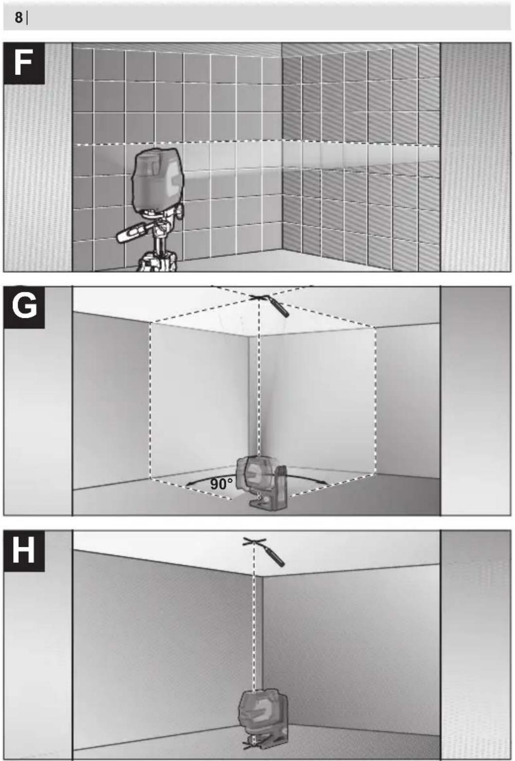
- Cross-line and point mode: The measuring tool generates a horizontal and a vertical laser line as well as two vertical laser points, one facing up, the other down. The laser lines cross at a 90^ angle.
- Horizontal line mode: The measuring tool generates a horizontal laser line in front of it.
- Vertical line mode: The measuring tool generates a vertical laser line in front of it. Positioning the measuring tool in the room displays the vertical laser line on the ceiling beyond the top laser point.
If the measuring tool is positioned directly against a wall, the vertical laser line almost encircles the entire space (360° line). - Point mode: The measuring tool generates two vertical laser points, one facing up, the other down.
To change the operating mode, press the button for laser operating mode (3) as often as required until the laser beams are generated in the required operating mode.
All operating modes can be used with both automatic levelling and the incline function.
All operating modes are suitable for operation with the laser receiver (26).
Automatic Levelling
The measuring tool monitors the position at all times during operation. It works with automatic levelling during set-up within the self-levelling range of ±4^ . Outside of the self-levelling range, it will automatically switch to the incline function.
44 | English
Working with Automatic Levelling
Position the measuring tool on a level, firm surface or attach it to the rotating mount (18) or the tripod (27).
The automatic levelling function automatically compensates irregularities within the self-levelling range of ±4^ . Once the laser beam is permanently lit, the measuring tool has levelled in.
If automatic levelling is not possible, e.g. because the surface on which the measuring tool stands deviates by more than 4^ from the horizontal plane, the laser lines will initially flash quickly for 2 seconds, then quickly flash every 5 seconds several times. The measuring tool is in the incline function.
For additional work with automatic levelling, set up the measuring tool so that it is horizontal and wait for the self-levelling procedure to complete. As soon as the measuring tool is within the self-levelling range of ±4^ , the laser beams will light up continuously. In case of ground vibrations or position changes during operation, the measuring tool is automatically levelled again. Upon levelling, check the position of the laser beams with regard to the reference points to avoid errors arising from a change in the measuring tool's position.
Working with the Incline Function
Place the measuring tool on an inclined surface. When working with the incline function, the laser lines will initially flash quickly for 2 seconds, then quickly flash every 5 seconds several times.
In the incline function, the laser lines are no longer levelled and no longer necessarily run perpendicular to one another.
Remote control via the Bosch Levelling Remote App
The measuring tool is equipped with a Bluetooth ^® module which uses radio technology to enable remote control via a smartphone with a Bluetooth ^® interface.
The Bosch Levelling Remote App application (app) is required to use this function. You can download this in the app store for your terminal device (Apple App Store, Google Play Store).
Information about system requirements for a Bluetooth ^® connection can be found on the Bosch website at www.bosch-pt.com.
When remote controlling via Bluetooth ^® , poor reception conditions can cause time delays between the mobile terminal device and the measuring tool.
Establishing/Ending a Connection to a Mobile Device
After the measuring tool has been switched on, the Bluetooth ^® function is always switched off.
To switch on the Bluetooth® function for remote control:
- Briefly press the Bluetooth® button (2). The button will slowly flash to provide confirmation.
- If the measuring tool has already been connected to a mobile device and this mobile device is within range (with the Bluetooth® interface activated), the connection to this mobile device is automatically re-established. The connection is successfully established as soon as the Bluetooth® button (2) lights up continuously.
The Bluetooth ^® connection may be interrupted if the distance between the measuring tool and the mobile device is too great or is blocked, and if there are any sources of electromagnetic interference. Should this occur, the Bluetooth ^® button (2) will flash.
To establish a new connection (first-time connection or connection to another mobile device):
- Ensure that the Bluetooth® interface is activated on the mobile device and that Bluetooth® is activated on the measuring tool.
- Load the Bosch Levelling Remote App. If multiple active measuring tools are found, select the appropriate measuring tool.
- Press and hold the Bluetooth® button (2) on the measuring tool until the button begins rapidly flashing.
- Confirm the connection on your mobile device.
- The connection is successfully established as soon as the Bluetooth® button (2) lights up continuously.
- If it is not possible to make a connection, the Bluetooth® button (2) continues to flash rapidly.
To switch off the Bluetooth® function:
Briefly press the Bluetooth® button (2) so that its light goes out or switch off the measuring tool.
Resetting to Factory Settings:
- When you reset the device to factory settings, all of the connection data in the measuring tool will be deleted.
- If the measuring tool has already been connected to a mobile device and this mobile device is within range, either switch off the Bluetooth® function or delete the connection to the measuring tool on the end device.
- Switch on the measuring tool. Then, briefly press the Bluetooth® button (2) on the measuring tool. The button will slowly flash to provide confirmation.
- Then press the Bluetooth® button (2) and the laser operating mode button (3) next to it simultaneously for 3 s until the Bluetooth® button (2) lights up briefly and goes out again.
46 | English
- The measuring tool is reset to factory settings.
Measuring Tool Software Update
If there is a software update available for the measuring tool, a notification will appear in the Bosch Levelling Remote App. To install the update, follow the instructions in the app.
During the update, the Bluetooth® button (2) will flash quickly. All of the other buttons will be deactivated and the laser lines will be switched off until the update has been successfully installed.
Accuracy Check of the Measuring Tool
Influences on Accuracy
The largest influence is exerted by the ambient temperature. In particular, temperature differences that occur from the ground upwards can refract the laser beam.
In order to minimise thermal influences resulting from heat rising from the floor, it is recommended that you use the measuring tool on a tripod. In addition, position the measuring tool in the centre of the work surface, wherever this is possible.
In addition to external influences, device-specific influences (e.g. falls or heavy impacts) can also lead to deviations. For this reason, check the levelling accuracy each time before beginning work.
First check the height accuracy and levelling accuracy of the horizontal laser line, then the levelling accuracy of the vertical laser line and the plumb accuracy.
Should the measuring tool exceed the maximum deviation during one of the tests, please have it repaired by a Bosch after-sales service.
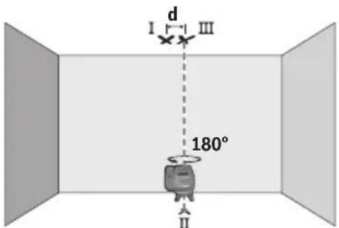
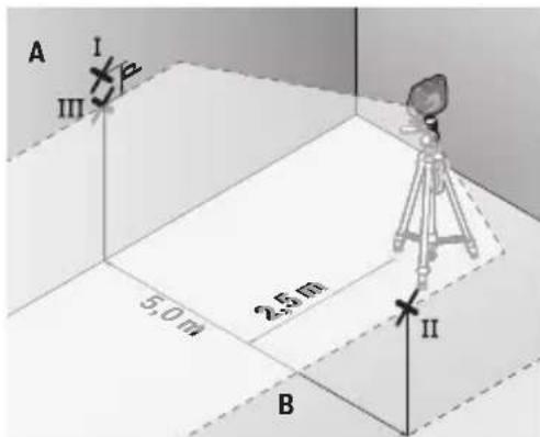
Checking the Height Accuracy of the Horizontal Line
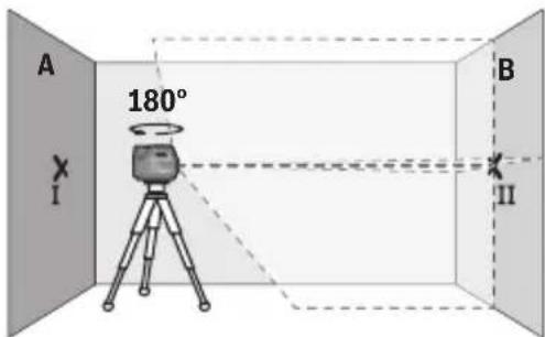
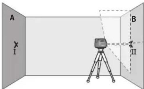
For this check, you will need a free measuring distance of 5 m on firm ground between two walls (designated A and B).
- Mount the measuring tool close to wall A on a tripod, or place it on a firm, level surface. Switch on the measuring tool and select cross-line operation.
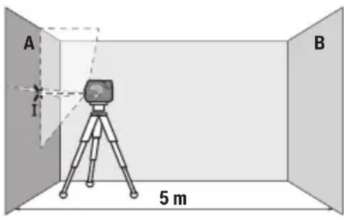
- Aim the laser at the closer wall A and allow the measuring tool to level in. Mark the middle of the point at which the laser lines cross on the wall (point I).
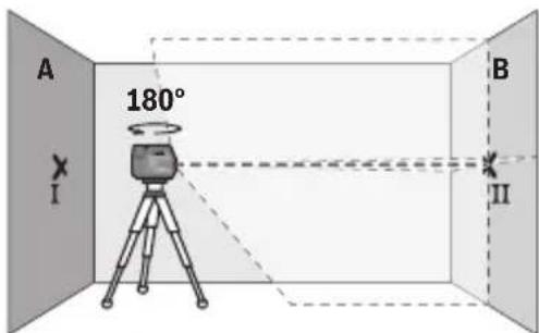
- Turn the measuring tool 180^ , allow it to level in and mark the point where the laser lines cross on the opposite wall B (point II).
- Position the measuring tool – without rotating it – close to wall B, switch it on and allow it to level in.

- Align the height of the measuring tool (using the tripod or by placing objects underneath as required) so that the point where the laser lines cross exactly hits the previously marked point II on wall B.
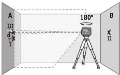
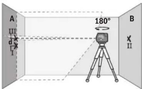
- Turn the measuring tool 180^ without adjusting the height. Aim it at wall A such that the vertical laser line runs through the already marked point I. Allow the measuring tool to level in and mark the point where the laser lines cross on wall A (point III).
- The discrepancy d between the two marked points I and III on wall A reveals the actual height deviation of the measuring tool.
The maximum permitted deviation on the measuring distance of 2 × 5 m = 10 m is as follows:
10 m × ±0.3 mm/m = ±3 mm. The discrepancy d between points I and III must therefore amount to no more than 3 mm.
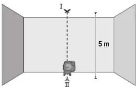
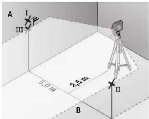
Checking the Level Accuracy of the Horizontal Line
For this check, you will need a free area of 5 × 5 m.
- Mount the measuring tool in the middle between walls A and B on a tripod, or place it on a firm, level surface. Switch on the measuring tool and select horizontal line mode. Allow the measuring tool to level in.
48 | English
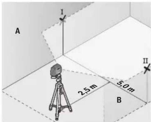
- At a distance of 2.5 m from the measuring tool, mark the centre of the laser line on both walls (point I on wall A and point II on wall B).
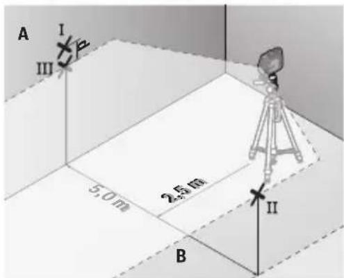
- Set up the measuring tool at a 5 m distance and rotated by 180^ and allow it to level in.
- Align the height of the measuring tool (using the tripod or by placing objects underneath as required) so that the centre of the laser line exactly hits the previously marked point II on wall B.
- Mark the centre of the laser line on wall A as point III (vertically above or below point I).
- The discrepancy d between the two marked points I and III on wall A reveals the actual horizontal deviation of the measuring tool.
The maximum permitted deviation on the measuring distance of 2 × 5 m = 10 m is as follows:
10 m × ±0.3 mm/m = ±3 mm. The discrepancy d between points I and III must therefore amount to no more than 3 mm.
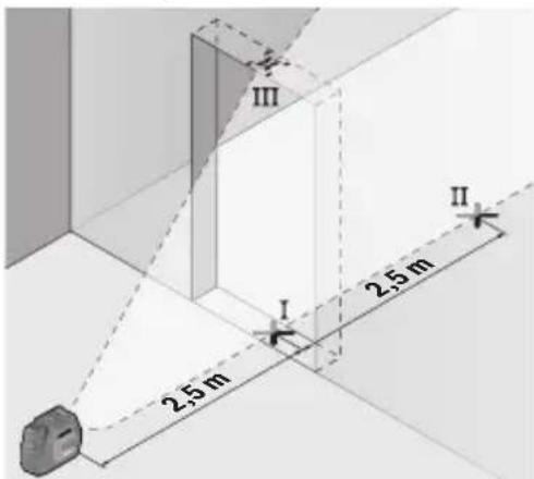
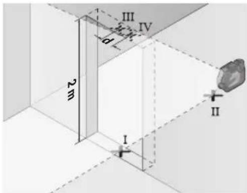
Checking the Level Accuracy of the Vertical Line
For this check, you will need a door opening (on solid ground) which has at least 2.5 m of space either side of the door.
- Place the measuring tool 2.5 m away from the door opening on a firm, flat surface (not on a tripod). Switch on the measuring tool and select vertical line mode. Aim the laser line at the door opening and allow the measuring tool to level in.
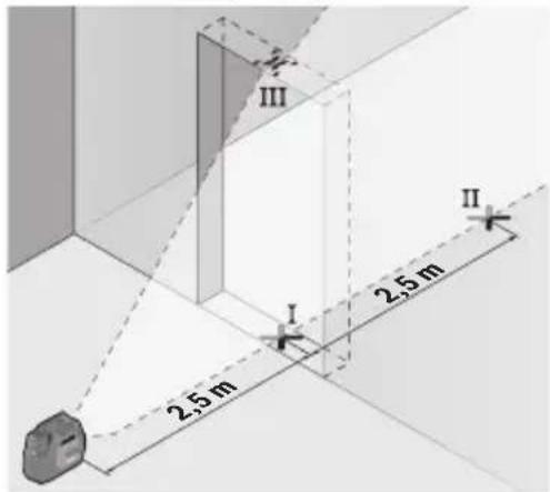
- Mark the centre of the vertical laser line on the floor of the door opening (point I), 5 m away on the other side of the door opening (point II) and on the upper edge of the door opening (point III).
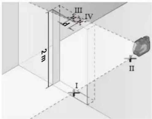
- Rotate the measuring tool 180^ and position it on the other side of the door opening, directly behind point II. Allow the measuring tool to level in and align the vertical laser line in such a way that its centre passes through points I and II exactly.
- Mark the centre of the laser line on the upper edge of the door opening as point IV.
- The discrepancy d between the two marked points III and IV reveals the actual vertical deviation of the measuring tool.
- Measure the height of the door opening.
You can calculate the maximum permitted deviation as follows:
Doubled height of the door opening × 0.3 mm/m
Example: At a door opening height of 2 m, the maximum deviation amounts to
2 × 2 m × ± 0.3 mm/m = ± 1.2 mm . The points III and IV must therefore be no further than 1.2 mm from each other.
Checking Plumb Accuracy
For this check, you will need a clear measuring space on firm ground with a distance of approx. 5 m between the floor and the ceiling.
50 | English
- Mount the measuring tool onto the rotating mount (18) and place it on the floor. Switch on the measuring tool and select point mode. Allow the measuring tool to level in.
- Mark the centre of the top laser point on the ceiling (point I). Also mark the centre of the bottom laser point on the floor (point II).
- Turn the measuring tool by 180^ . Position it so that the centre of the bottom laser point falls onto the marked point II. Allow the measuring tool to level in. Mark the centre of the top laser point (point III).
- The discrepancy d between the two marked points I and III on the ceiling reveals the actual deviation of the measuring tool from the vertical plane.
You can calculate the maximum permitted deviation as follows:
Doubled distance between floor and ceiling × 0.7 mm/m
Example: At a floor-to-ceiling distance of 5 m, the maximum deviation amounts to
2 × 5 m × ± 0.7 mm/m = ± 7 mm . The points I and III must therefore be no further than 7 mm from each other.
Working Advice
▶ Only the centre of the laser point or laser line must be used for marking. The size of the laser point/the width of the laser line changes depending on the distance.
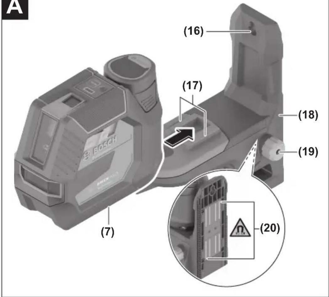
Working with the RM 20 Rotating Mount (see figures A–D)
You can use the rotating mount (18) to rotate the measuring tool 200^ around a central, always visible plumb point. This enables you to align the laser lines without having to change the position of the measuring tool.
You can use the fine adjustment screw (19) to align vertical laser lines precisely with reference points.
Place the measuring tool with the guide groove (7) on the guide rail (17) of the rotating mount (18) and slide the measuring tool all the way onto the platform.
To disconnect the measuring tool, pull it off the rotating mount in the opposite direction.
Positioning possibilities of the rotating mount:
- Standing on a flat surface,
- Screwed to a vertical surface,
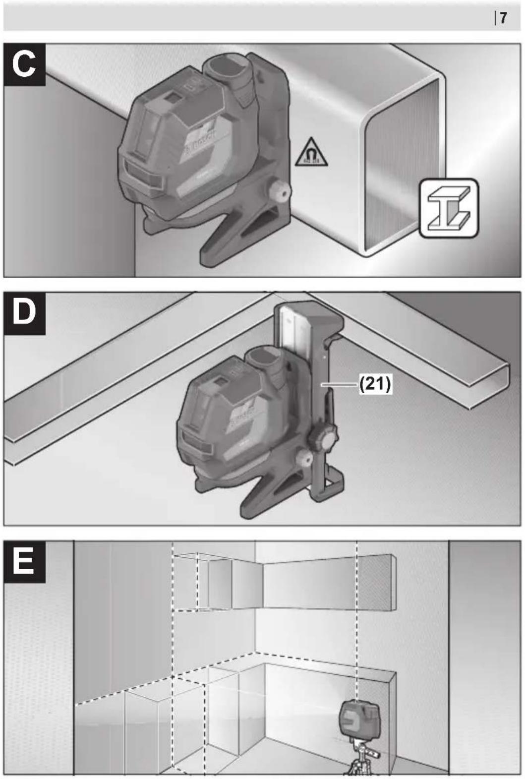
- On metallic surfaces using the magnets (20),
- On crown moulding using the ceiling clip (21).
- Keep your fingers away from the rear side of the magnetic accessory while attaching the accessory to surfaces. The strong pulling force of the magnets may jam your fingers.
Roughly align the rotating mount (18) before switching on the measuring tool.
Working with the Laser Target Plate
The laser target plate (24) improves visibility of the laser beam in unfavourable conditions and at greater distances.
The reflective surface of the laser target plate (24) improves visibility of the laser line. The transparent surface enables the laser line to be seen from behind the laser target plate.
Working with the Tripod
A tripod offers a stable, height-adjustable support surface for measuring. Place the measuring tool with the 1/4" tripod mount (6) on the thread of the tripod (27) or a conventional camera tripod. Tighten the measuring tool using the locking screw of the tripod.
Roughly align the tripod before switching on the measuring tool.
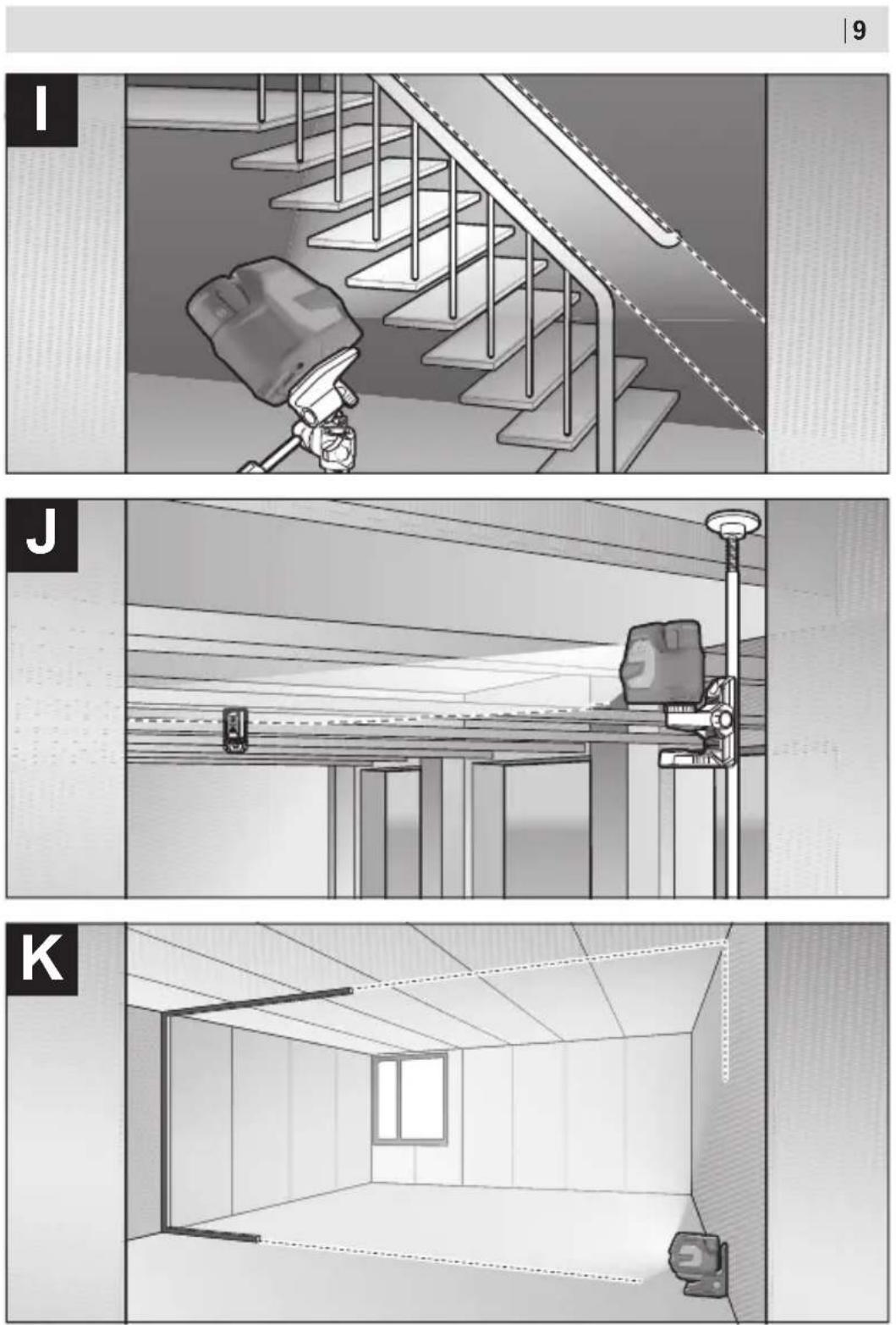
Attaching with the Universal Holder (see figure J)
You can secure the measuring tool, for example, on vertical surfaces or magnetisable materials using the universal holder (22). The universal holder is also suitable for use as a floor stand and facilitates the height adjustment of the measuring tool.
- Keep your fingers away from the rear side of the magnetic accessory while attaching the accessory to surfaces. The strong pulling force of the magnets may jam your fingers.
Roughly align the universal holder (22) before switching on the measuring tool.
52 | English
Working with the Holder LB 10
You can secure the measuring tool on vertical surfaces or magnetisable materials using the holder (23). In conjunction with the ceiling clip (21), the measuring tool can also be aligned vertically.
- Keep your fingers away from the rear side of the magnetic accessory while attaching the accessory to surfaces. The strong pulling force of the magnets may jam your fingers.
Roughly align the holder (23) before switching on the measuring tool.
Working with the Laser Receiver (see figure J)
Use the laser receiver (26) to improve detection of the laser lines in adverse lighting conditions (bright environment, direct sunlight) and over greater distances.
All operating modes are suitable for operation with the laser receiver (26).
Laser Goggles
The laser goggles filter out ambient light. This makes the light of the laser appear brighter to the eye.
▶ Do not use the laser goggles (accessory) as protective goggles. The laser goggles make the laser beam easier to see; they do not protect you against laser radiation.
▶ Do not use the laser goggles (accessory) as sunglasses or while driving. The laser goggles do not provide full UV protection and impair your ability to see colours.
Example applications (see figures E-K)
Examples of possible applications for the measuring tool can be found on the graphics pages.
Maintenance and Service
Maintenance and Cleaning
Keep the measuring tool clean at all times.
Never immerse the measuring tool in water or other liquids.
Wipe off any dirt using a damp, soft cloth. Do not use any detergents or solvents.
The areas around the outlet aperture of the laser in particular should be cleaned on a regular basis. Make sure to check for lint when doing this.
Only store and transport the measuring tool in the protective bag (30) or the case (31).
If the measuring tool needs to be repaired, send it off in the protective bag (30) or the case (31).
After-Sales Service and Application Service
Our after-sales service responds to your questions concerning maintenance and repair of your product as well as spare parts. You can find explosion drawings and information on spare parts at: www.bosch-pt.com
The Bosch product use advice team will be happy to help you with any questions about our products and their accessories.
In all correspondence and spare parts orders, please always include the 10-digit article number given on the nameplate of the product.
Great Britain
Robert Bosch Ltd. (B.S.C.)
P.O. Box 98
Broadwater Park
North Orbital Road
Denham Uxbridge
UB 9 5HJ
At www.bosch-pt.co.uk you can order spare parts or arrange the collection of a product in need of servicing or repair.
Tel. Service: (0344) 7360109
E-Mail: boschservicecentre@bosch.com
You can find further service addresses at:
www.bosch-pt.com/serviceaddresses
Transport
The recommended lithium-ion batteries are subject to legislation on the transport of dangerous goods. The user can transport the batteries by road without further requirements.
When the batteries are shipped by third parties (e.g. air transport or forwarding agency), special requirements on packaging and labelling (e.g. ADR regulations) must be met. A dangerous goods expert must be consulted when preparing the items for shipping.
Dispatch battery packs only when the housing is undamaged. Tape or mask off open contacts and pack up the battery in such a manner that it cannot move around in the packaging. Please also observe the possibility of more detailed national regulations.
Disposal

Measuring tools, rechargeable/non-rechargeable batteries, accessories and packaging should be sorted for environmental-friendly recycling.
54 | Français
Do not dispose of the measuring tools or battery packs/batteries with household waste.
Only for EU countries:
Measuring tools that are no longer suitable for use and defective or used rechargeable batteries/batteries must be disposed of separately. Use the designated collection systems.
If disposed incorrectly, waste electrical and electronic equipment may have harmful effects on the environment and human health, due to the potential presence of hazardous substances.
Only for United Kingdom:
According to The Waste Electrical and Electronic Equipment Regulations 2013 (SI 2013/3113) (as amended) and the Waste Batteries and Accumulators Regulations 2009 (SI 2009/890) (as amended), products that are no longer usable must be collected separately and disposed of in an environmentally friendly manner.
Battery packs/batteries:
Li-ion:
Please observe the notes in the section on transport (see "Transport", page 53).
Français
Robert Bosch (France) S.A.S.
www.bosch-pt.com/serviceaddresses
Transport
natural_image
Symbolic icon of a person moving with arrows, enclosed in a circle (no text or symbols)
Calle Robert Bosch No. 405
www.bosch-pt.com/serviceaddresses
98 | Español
Transporte
Controlo remoto via "Bosch Levelling Remote App"
www.bosch-pt.com/serviceaddresses
Transporte
www.bosch-pt.com/serviceaddresses
Trasporto
www.bosch-pt.com/serviceaddresses
Vervoer
Bosch Service Center
Telegrafvej 3
2750 Ballerup
På www.bosch-pt.dk kan der online bestilles reservedele eller oprettes en reparations ordre.
Tlf. Service Center: 44898855
Fax: 44898755
E-Mail: vaerktoej@dk.bosch.com
Yderligere serviceadresser findes under:
www.bosch-pt.com/serviceaddresses
Transport
Fjärrstyrning via "Bosch Levelling Remote App"
Bosch Service Center
Telegrafvej 3
2750 Ballerup
Danmark
Tel.: (08) 7501820 (inom Sverige)
Fax: (011) 187691
Vidare serviceadresser finner du under:
www.bosch-pt.com/serviceaddresses
Transport
www.bosch-pt.com/serviceaddresses
Transport
www.bosch-pt.com/serviceaddresses
Kuljetus
www.bosch-pt.com/serviceaddresses
262 | Ελληνικά
Μεταφορά
www.bosch-pt.com/serviceaddresses
Taşıma
Robert Bosch Sp. z o.o.
www.bosch-pt.com/serviceaddresses
Transport
Bosch Service Center PT
K Vápence 1621/16
692 01 Mikulov
www.bosch-pt.com/serviceaddresses
Přeprava
www.bosch-pt.com/serviceaddresses
Preprava
www.bosch-pt.com/serviceaddresses
Szállítás
www.bosch-pt.com/serviceaddresses
Транспортировка
www.bosch-pt.com/serviceaddresses
Транспортування
www.bosch-pt.com/serviceaddresses
Тасымалдау
odds funds mgg on y60s h5u30n odds funds mgg on z50sdy35bdn.
- ∂∂∂∂∂∂∂∂∂∂∂∂∂∂∂∂∂∂∂∂∂∂∂∂∂∂∂∂∂∂∂∂∂∂∂∂∂∂∂∂∂∂∂∂∂∂∂∂∂∂∂∂∂∂∂∂∂∂∂∂∂∂∂∂∂∂∂∂∂∂∂∂∂∂∂∂∂∂∂∂∂∂∂∂∂∂∂∂∂∂∂∂∂∂∂∂∂∂∂∂∂Δροσεραραραραραραραραραραραραραραραραραραραραραραραραραραραραραραραραραραραραραραραραραραραραραραραραραραρ αροσεραραραραραραραραραραραραραραραραραραραραραραραραραραραραραραραραραραραραραραραραραραραραραραραρ αροσέπαι δυδυδυδυδυδυδυδυδυδυδυδυδυδυδυδυδυδυδυδυδυδυδυδυδυδυδυδυδυδυδυδυδυδυδυδυδυδυδυδυδυδυδυδυδυδυδυδυδυδυδυ δυδυδυδυδυδυδυδυδυδυδυδυδυδυδυδυδυδυδυδυδυδυδυδυδυδυδυδυδυδυδυδυδυδυδυδυδυδυδυδυδυδυδυδυδυδυδυδυ δυκεύντων Φους υπικόντων υπικόντων υπικόντων υπικόντων υπικόντων υπικόντων υπικόντων υπικόντων υπικόντων υπικόντων υπικόντω νομούς.
450 | ʃʊmənɡən
modification of the following forms:
Fig.6037: 12-14. The following table contains the following table in the image:
www.bosch-pt.com
Bosch-nu 3m6bμmθδs6θns zg6ωn lnsdμ36gδοσ φωzgbdsmgδοσ bγδολαŋm lusznoblus σγ δj3nnb3suns6 φω3s3dnmgδοσ, ἐmdgμην δγndmγδ s δμ6φωσ dμ6bροπgδγμ m bμnlsfμymgδοns6 ωs sβμ2μ5mγδοns6 φω3s3dnmgδοσ. πnsndg 3nnb3gδοι fβsmdmβd6suns6 φω3s3dnmgδοι dγdmb3g3sδ o δ lusnsφωsπσm bβfnmgδοι dj33g0nnbsi sγβnμγδmsφ δηγοπομσ ζόμφγβσοι 10-6nd6s luslsfμ6mm δmΔgμο. μι δmΔgμο δγndmμσον ονομμον bμnlsfμyml fμmb6γμ ΘΩΦΩnθδs8j.
LPSM30mm
www.bosch-pt.com/serviceaddresses
అనునంక్రిప్రామణి
Service scule electrice
Strada Horia Măcelariu Nr. 30–34, sector 1
013937 Bucureşti
www.bosch-pt.com/serviceaddresses
Transport
Service scule electrice
Strada Horia Măcelariu Nr. 30–34, sector 1
013937 Bucureşti, România
www.bosch-pt.com/bg/bg/
www.bosch-pt.com/serviceaddresses
Транспортиране
www.bosch-pt.com/serviceaddresses
Транспорт
www.bosch-pt.com/serviceaddresses
Transporti
- Usmerite laser na bliski zid A i pustite da se merni alat niveliše. Označite sredinu tačke na kojoj se laserske linije na zidu ukrštaju (tačka I).
- Okrenite merni alat za 180°, pustite da se niveliše i označite tačku ukrštanja laserskih linija na suprotnom zidu B (tačka II).
- Stavite merni alat - bez okretanja - blizu zida B, uključite ga i pustite da se niveliše.
- Merni alat usmerite u vis tako (pomoću stativa ili po potrebi podmetanjem), da tačka ukrštanja laserskih linija tačno pogada prethodno označenu tačku II na zidu B.
- Merni alat okrenite za 180°, a da ne pomerate visinu. Usmerite ga prema zidu A, tako da vertikalna laserska linija prolazi kroz već označenu tačku I. Pustite merni alat da se niveliše i označite tačku ukrštanja laserskih linija na zidu A (tačka III).
– Označite na 2,5 m udaljenosti od mernog alata na oba zida sredinu laserske linije (tačka I na zidu A i tačka II na zidu B).
558 | Srpski
- Postavite merni alat za 180° okrenut na 5 m udaljenosti i iznivelišite ga.
- Merni alat usmerite uvis tako (pomoću stativa ili po potrebi podmetanjem) da sredina laserske linije tačno pogađa prethodno označenu tačku II na zidu B.
– Označite na zidu A sredinu laserske linije kao tačku III (vertikalno iznad odn. ispod tačke I). - Razlika d između obe označene tačke I i III na zidu A predstavlja stvarno odstupanje mernog alata od horizontale.
Na mernoj deonici od 2 × 5 m = 10 m maksimalno dozvoljeno odstupanje iznosi: 10 m × ±0,3 mm/m = ±3 mm. Razlika d između tačaka I i III prema tome sme da iznosi maksimalno 3 mm.
Kontrola tačnosti nivelisanja vertikalne linije
Za kontrolu potreban Vam je otvor od vrata, kod kojih (na čvrstoj zemlji) sa svake strane vrata ima najmanje 2,5 m prostora.
- Postavite merni alat na 2,5 m rastojanja od otvora vrata na čvrstu ravnu podlogu (ne na stativ). Uključite merni alat i izaberite vertikalni linijski režim rada. Usmerite lasersku liniju na otvor vrata i iznivelišite merni alat.
– Označite sredinu vertikalne laserske linije na podu otvora za vrata (tačka I), na razdaljini od 5 m od druge strane otvora za vrata (tačka II) kao i na gornjoj ivici otvora za vrata (tačka III).

- Okrenite merni alat za 180° i stavite ga na drugu stranu otvora za vrata direktno iza tačke II. Pustite merni alat da se niveliše i vertikalnu lasersku liniju usmerite tako da njena sredina tačno kroz tačke I i II.
- Okrenite merni alat za 180°. Pozicionirajte ga tako da se sredina donje laserske tačke nalazi na već označenoj tački II. Pustite da se merni alat izniveliše. Označite sredinu gornje laserske tačke (tačka III).
www.bosch-pt.com/serviceaddresses
Transport
Sadržani litijum-jonski akumulatori podležu zahtevima zakona o opasnim materijalima.
Korisnik može da transportuje akumulatore kopnenim putem bez dodatnih uslova.
Kod slanja preko posrednika (npr.: vazdušnim transportom ili otpremom) treba poštovati posebne zahteve u pogledu pakovanja i označavanja. Pri tome je kod pripreme pošiljke potrebno angažovati stručnjaka za opasne materijale.
Šaljite akumulatore samo ako je kućište neoštećeno. Otvorene kontakte odlepite i tako upakujte akumulator da se u pakovanju ne pokreće. Molimo da obratite pažnju i na eventualne dodatne nacionalne propise.
Uklanjanje dubreta

Merne alate, akumulatore/baterije, pribor i pakovanja treba predati na reciklažu koja je u skladu sa zaštitom životne sredine.
Merne alate i akumulatorske baterije/baterije nemojte bacati u kućni otpad!
Samo za EU-zemlje:
Merni alati koji se više ne mogu koristiti i neispravni ili istrošeni akumulatori/baterije moraju da se odlažu u otpad odvojeno. Koristite predviđene sisteme za sakupljanje.
- Na oddaljenosti 2,5 m od merilne naprave na obeh stenah označite sredino laserske linije (točka I na steni A in točka II na steni B).
578 | Slovenščina
- Merilno napravo obrnite za 180°, jo postavite 5 m stran od stene in počakajte, da se uravna.
www.bosch-pt.com/serviceaddresses
Transport
- Na udaljenosti 2,5 m od mjernog alata označite na oba zida sredinu linije lasera (točka I na zidu A i točka II na zidu B).

- Postavite mjerni alat okrenut za 180° na udaljenosti 5 m i iznivelirajte ga.
– Mjerni alat usmjerite po visini (pomoću stativa ili eventualno podlaganjem) tako da sredina linije lasera točno udara na prethodno označenu točku II na zidu B.
– Na zidu A označite sredinu linije lasera kao točku III (okomito iznad odn. ispod točke I).
- Razlika d obje označene točke I i III na zidu A daje stvarno odstupanje mjernog alata od horizontale.
– Označite sredinu okomite linije lasera na dnu otvora vrata (točka I), na udaljenosti 5 m na drugoj strani otvora vrata (točka II) kao i na gornjem rubu otvora vrata (točka III).
- Okrenite mjerni alat za 180°.
Pozicionirajte ga tako da sredina donje točke lasera pada na već označenu točku II. Iznivelirajte mjerni alat.
www.bosch-pt.com/serviceaddresses
Transport
www.bosch-pt.com/serviceaddresses
Transport
www.bosch-pt.com/serviceaddresses
Transportēšana
www.bosch-pt.com/serviceaddresses
Transportavimas
سقف تفاوتاalcيقيا-
(E-KAmthla Shgl (anpralpur)
Robert Bosch Morocco SARL
www.bosch-pt.com/serviceaddresses
النقل
"Bosch Levelling Remote App,,
نطه IV علامتگذاری-
اختلاف واقعى ابزار-
- اختلاف قعى ابزار
Legal Information and Licenses
CMSIS Version 5, v5.6.0
Apache-2.0
Copyright © 2009-2019 Arm Limited. All rights reserved.
Licensed under the Apache License, Version 2.0 (the "License"); you may not use this file except in compliance with the License.
You may obtain a copy of the License at http://www.apache.org/licenses/LICENSE-2.0
Unless required by applicable law or agreed to in writing, software distributed under the License is distributed on an "AS IS" BASIS, WITHOUT WARRANTIES OR CONDITIONS OF ANY KIND, either express or implied. See the License for the specific language governing permissions and limitations under the License.
STM32CubeG0, v1.5.1
Apache-2.0
Copyright © 2018-2021 STMicroelectronics.
Licensed under the Apache License, Version 2.0 (the "License"); you may not use this file except in compliance with the License.
You may obtain a copy of the License at http://www.apache.org/licenses/LICENSE-2.0
Unless required by applicable law or agreed to in writing, software distributed under the License is distributed on an "AS IS" BASIS, WITHOUT WARRANTIES OR CONDITIONS OF ANY KIND, either express or implied.
See the License for the specific language governing permissions and limitations under the License.
SIMPLELINK-CC13XX-CC26XX-SDK, 6.20.00.29
Copyright © 2015, Texas Instruments Incorporated
All rights reserved not granted herein. Limited License.
Texas Instruments Incorporated grants a world-wide, royalty-free, non-exclusive license under copyrights and patents it now or hereafter owns or controls to make, have made, use, import, offer to sell and sell ("Utilize") this software subject to the terms herein. With respect to the foregoing patent license, such license is granted solely to the extent that any such patent is necessary to Utilize the software alone. The patent license shall not apply to any combinations which include this software, other than combinations with devices manufactured by or for TI ("TI Devices"). No hardware patent is licensed hereunder.
Redistributions must preserve existing copyright notices and reproduce this license (including the above copyright notice and the disclaimer and (if applicable) source code license limitations below) in the documentation and/or other materials provided with the distribution.
Redistribution and use in binary form, without modification, are permitted provided that the following conditions are met:
- No reverse engineering, decompilation, or disassembly of this software is permitted with respect to any software provided in binary form.
– Any redistribution and use are licensed by TI for use only with TI Devices.
- Nothing shall obligate TI to provide you with source code for the software licensed and provided to you in object code.
If software source code is provided to you, modification and redistribution of the source code are permitted provided that the following conditions are met:
708 | Legal Information and Licenses
– Any redistribution and use of the source code, including any resulting derivative works, are licensed by TI for use only with TI Devices.
– Any redistribution and use of any object code compiled from the source code and any resulting derivative works, are licensed by TI for use only with TI Devices.
- Neither the name of Texas Instruments Incorporated nor the names of its suppliers may be used to endorse or promote products derived from this software without specific prior written permission.
DISCLAIMER.
THIS SOFTWARE IS PROVIDED BY TI AND TI'S LICENSORS "AS IS" AND ANY EXPRESS OR IMPLIED WARRANTIES, INCLUDING, BUT NOT LIMITED TO, THE IMPLIED WARRANTIES OF MERCHANTABILITY AND FITNESS FOR A PARTICULAR PURPOSE ARE DISCLAIMED. IN NO EVENT SHALL TI AND TI'S LICENSORS BE LIABLE FOR ANY DIRECT, INDIRECT, INCIDENTAL, SPECIAL, EXEMPLARY, OR CONSEQUENTIAL DAMAGES (INCLUDING, BUT NOT LIMITED TO, PROCUREMENT OF SUBSTITUTE GOODS OR SERVICES; LOSS OF USE, DATA, OR PROFITS; OR BUSINESS INTERRUPTION) HOWEVER CAUSED AND ON ANY THEORY OF LIABILITY, WHETHER IN CONTRACT, STRICT LIABILITY, OR TORT (INCLUDING NEGLIGENCE OR OTHERWISE) ARISING IN ANY WAY OUT OF THE USE OF THIS SOFTWARE, EVEN IF ADVISED OF THE POSSIBILITY OF SUCH DAMAGE.
Copyright 2010 - 2015 Texas Instruments Incorporated. All rights reserved.
Copyright © 2016 Texas Instruments Incorporated – http://www.ti.com/
All rights reserved not granted herein. Limited License.
Texas Instruments Incorporated grants a world-wide, royalty-free, non-exclusive license under copyrights and patents it now or hereafter owns or controls to make, have made, use, import, offer to sell and sell ("Utilize") this software subject to the terms herein. With respect to the foregoing patent license, such license is granted solely to the extent that any such patent is necessary to Utilize the software alone. The patent license shall not apply to any combinations which include this software, other than combinations with devices manufactured by or for TI ("TI Devices"). No hardware patent is licensed hereunder. Redistributions must preserve existing copyright notices and reproduce this license (including the above copyright notice and the disclaimer and (if applicable) source code license limitations below) in the documentation and/or other materials provided with the distribution.
Redistribution and use in binary form, without modification, are permitted provided that the following conditions are met:
- No reverse engineering, decompilation, or disassembly of this software is permitted with respect to any software provided in binary form.
– Any redistribution and use are licensed by TI for use only with TI Devices. - Nothing shall obligate TI to provide you with source code for the software licensed and provided to you in object code.
If software source code is provided to you, modification and redistribution of the source code are permitted provided that the following conditions are met:
– Any redistribution and use of the source code, including any resulting derivative works, are licensed by TI for use only with TI Devices.
– Any redistribution and use of any object code compiled from the source code and any resulting derivative works, are licensed by TI for use only with TI Devices.
- Neither the name of Texas Instruments Incorporated nor the names of its suppliers may be used to endorse or promote products derived from this software without specific prior written permission.
DISCLAIMER.
THIS SOFTWARE IS PROVIDED BY TI AND TI'S LICENSORS "AS IS" AND ANY EXPRESS OR IMPLIED WARRANTIES, INCLUDING, BUT NOT LIMITED TO, THE IMPLIED WARRANTIES OF MERCHANTABILITY AND FITNESS FOR A PARTICULAR PURPOSE ARE DISCLAIMED. IN NO EVENT SHALL TI AND TI'S LICENSORS BE LIABLE FOR ANY DIRECT, INDIRECT, INCIDENTAL, SPECIAL, EXEMPLARY, OR CONSEQUENTIAL DAMAGES (INCLUDING, BUT NOT LIMITED TO, PROCUREMENT OF SUBSTITUTE GOODS OR SERVICES; LOSS OF USE, DATA, OR PROFITS; OR BUSINESS INTERRUPTION) HOWEVER CAUSED AND ON ANY THEORY OF LIABILITY, WHETHER IN CONTRACT, STRICT LIABILITY, OR TORT (INCLUDING NEGLIGENCE OR OTHERWISE) ARISING IN ANY WAY OUT OF THE USE OF THIS SOFTWARE, EVEN IF ADVISED OF THE POSSIBILITY OF SUCH DAMAGE.
Generic License Text
Apache License 2.0
Apache License Version 2.0, January 2004
http://www.apache.org/licenses/
TERMS AND CONDITIONS FOR USE, REPRODUCTION, AND DISTRIBUTION
Definitions.
"License" shall mean the terms and conditions for use, reproduction, and distribution as defined by Sections 1 through 9 of this document.
"Licensor" shall mean the copyright owner or entity authorized by the copyright owner that is granting the License.
"Legal Entity" shall mean the union of the acting entity and all other entities that control, are controlled by, or are under common control with that entity. For the purposes of this definition, "control" means (i) the power, direct or indirect, to cause the direction or management of such entity, whether by contract or otherwise, or (ii) ownership of fifty percent (50%) or more of the outstanding shares, or (iii) beneficial ownership of such entity.
"You" (or "Your") shall mean an individual or Legal Entity exercising permissions granted by this License.
"Source" form shall mean the preferred form for making modifications, including but not limited to software source code, documentation source, and configuration files.
"Object" form shall mean any form resulting from mechanical transformation or translation of a Source form, including but not limited to compiled object code, generated documentation, and conversions to other media types.
"Work" shall mean the work of authorship, whether in Source or Object form, made available under the License, as indicated by a copyright notice that is included in or attached to the work (an example is provided in the Appendix below).
"Derivative Works" shall mean any work, whether in Source or Object form, that is based on (or derived from) the Work and for which the editorial revisions, annotations, elaborations, or other modifications represent, as a whole, an original work of authorship. For the purposes of this License, Derivative Works shall not include works that remain separable from, or merely link (or bind by name) to the interfaces of, the Work and Derivative Works thereof.
"Contribution" shall mean any work of authorship, including the original version of the Work and any modifications or additions to that Work or Derivative Works thereof, that is intentionally submitted to Licensor for inclusion in the Work by the copyright owner or by an individual or Legal Entity authorized to submit on behalf of the copyright owner. For the purposes of this definition, "submitted" means any form of electronic, verbal, or written communication sent to the Licensor or its representatives, including but not limited to communication on electronic mailing lists, source code control systems, and issue tracking
710 | Legal Information and Licenses
systems that are managed by, or on behalf of, the Licensor for the purpose of discussing and improving the Work, but excluding communication that is conspicuously marked or otherwise designated in writing by the copyright owner as "Not a Contribution."
"Contributor" shall mean Licensor and any individual or Legal Entity on behalf of whom a Contribution has been received by Licensor and subsequently incorporated within the Work.
Grant of Copyright License. Subject to the terms and conditions of this License, each Contributor hereby grants to You a perpetual, worldwide, non-exclusive, no-charge, royalty-free, irrevocable copyright license to reproduce, prepare Derivative Works of, publicly display, publicly perform, sublicense, and distribute the Work and such Derivative Works in Source or Object form.
Grant of Patent License. Subject to the terms and conditions of this License, each Contributor hereby grants to You a perpetual, worldwide, non-exclusive, no-charge, royalty-free, irrevocable (except as stated in this section) patent license to make, have made, use, offer to sell, sell, import, and otherwise transfer the Work, where such license applies only to those patent claims licensable by such Contributor that are necessarily infringed by their Contribution(s) alone or by combination of their Contribution(s) with the Work to which such Contribution(s) was submitted. If You institute patent litigation against any entity (including a cross-claim or counterclaim in a lawsuit) alleging that the Work or a Contribution incorporated within the Work constitutes direct or contributory patent infringement, then any patent licenses granted to You under this License for that Work shall terminate as of the date such litigation is filed.
Redistribution. You may reproduce and distribute copies of the Work or Derivative Works thereof in any medium, with or without modifications, and in Source or Object form, provided that You meet the following conditions:
(a) You must give any other recipients of the Work or Derivative Works a copy of this License; and
(b) You must cause any modified files to carry prominent notices stating that You changed the files; and
(c) You must retain, in the Source form of any Derivative Works that You distribute, all copyright, patent, trademark, and attribution notices from the Source form of the Work, excluding those notices that do not pertain to any part of the Derivative Works; and
(d) If the Work includes a "NOTICE" text file as part of its distribution, then any Derivative Works that You distribute must include a readable copy of the attribution notices contained within such NOTICE file, excluding those notices that do not pertain to any part of the Derivative Works, in at least one of the following places: within a NOTICE text file distributed as part of the Derivative Works; within the Source form or documentation, if provided along with the Derivative Works; or, within a display generated by the Derivative Works, if and wherever such third-party notices normally appear. The contents of the NOTICE file are for informational purposes only and do not modify the License. You may add Your own attribution notices within Derivative Works that You distribute, alongside or as an addendum to the NOTICE text from the Work, provided that such additional attribution notices cannot be construed as modifying the License.
You may add Your own copyright statement to Your modifications and may provide additional or different license terms and conditions for use, reproduction, or distribution of Your modifications, or for any such Derivative Works as a whole, provided Your use, reproduction, and distribution of the Work otherwise complies with the conditions stated in this License.
Submission of Contributions. Unless You explicitly state otherwise, any Contribution intentionally submitted for inclusion in the Work by You to the Licensor shall be under the terms and conditions of this License, without any additional terms or conditions. Notwithstanding the above, nothing herein shall supersede or modify the terms of any separate license agreement you may have executed with Licensor regarding such Contributions.
Legal Information and Licenses | 711
Trademarks. This License does not grant permission to use the trade names, trademarks, service marks, or product names of the Licensor, except as required for reasonable and customary use in describing the origin of the Work and reproducing the content of the NOTICE file.
Disclaimer of Warranty. Unless required by applicable law or agreed to in writing, Licensor provides the Work (and each Contributor provides its Contributions) on an "AS IS" BASIS, WITHOUT WARRANTIES OR CONDITIONS OF ANY KIND, either express or implied, including, without limitation, any warranties or conditions of TITLE, NON-INFRINGEMENT, MERCHANTABILITY, or FITNESS FOR A PARTICULAR PURPOSE. You are solely responsible for determining the appropriateness of using or redistributing the Work and assume any risks associated with Your exercise of permissions under this License.
Limitation of Liability. In no event and under no legal theory, whether in tort (including negligence), contract, or otherwise, unless required by applicable law (such as deliberate and grossly negligent acts) or agreed to in writing, shall any Contributor be liable to You for damages, including any direct, indirect, special, incidental, or consequential damages of any character arising as a result of this License or out of the use or inability to use the Work (including but not limited to damages for loss of goodwill, work stoppage, computer failure or malfunction, or any and all other commercial damages or losses), even if such Contributor has been advised of the possibility of such damages.
Accepting Warranty or Additional Liability. While redistributing the Work or Derivative Works thereof, You may choose to offer, and charge a fee for, acceptance of support, warranty, indemnity, or other liability obligations and/or rights consistent with this License. However, in accepting such obligations, You may act only on Your own behalf and on Your sole responsibility, not on behalf of any other Contributor, and only if You agree to indemnify, defend, and hold each Contributor harmless for any liability incurred by, or claims asserted against, such Contributor by reason of your accepting any such warranty or additional liability.
END OF TERMS AND CONDITIONS
Warranty Disclaimer
This product contains Open Source Software components which underly Open Source Software Licenses. Please note that Open Source Licenses contain disclaimer clauses. The text of the Open Source Licenses that apply are included in this manual under "Legal Information and Licenses".
712 | Legal Information and Licenses
CE
|
| de | Hiermit erklärt Robert Bosch Power Tools GmbH, dass der Funkanlagentyp GCL 12V-50-22 CG der Richtlinie 2014/53/EU entspricht. Der vollständige Text der EU-Konformitätserklärung ist unter der folgenden Internetadresse verfügbar: |
| en | Hereby, Robert Bosch Power Tools GmbH declares that the radio equipment type GCL 12V-50-22 CG is in compliance with Directive 2014/53/EU. The full text of the EU declaration of conformity is available at the following internet address: |
| fr | Le soussigné, Robert Bosch Power Tools GmbH, déclare que l'équipement radioélectrique du type GCL 12V-50-22 CG est conforme à la directive 2014/53/UE. Le texte complet de la déclaration UE de conformité est disponible à l'adresse internet suivante : |
| es | Por la presente, Robert Bosch Power Tools GmbH declara que el tipo de equipo radioeléctrico GCL 12V-50-22 CG es conforme con la Directiva 2014/53/UE. El texto completo de la declaración UE de conformidad está disponible en la dirección Internet siguiente: |
| pt | A abaixo assinada Robert Bosch Power Tools GmbH declara que o presente tipo de equipamento de rádio GCL 12V-50-22 CG está em conformidade com a Diretiva 2014/53/UE. O texto integral da declaração de conformidade está disponível no seguinte endereço de Internet: |
| it | Il fabbricante, Robert Bosch Power Tools GmbH, dichiara che il tipo di apparecchiatura radio GCL 12V-50-22 CG è conforme alla direttiva 2014/53/UE. Il testo completo della dichiarazione di conformità UE è disponibile al seguente indirizzo Internet: |
| nl | Hierbij verklaar ik, Robert Bosch Power Tools GmbH, dat het type radioapparatuur GCL 12V-50-22 CG conform is met Richtlijn 2014/53/EU. De volledige tekst van de EU-conformiteitsverklaring kan worden geraadpleegd op het volgende internetadres: |
| da | Hermed erklærer Robert Bosch Power Tools GmbH, at radioudstyrstypen GCL 12V-50-22 CG er i overensstemmelse med direktiv 2014/53/EU. EU-overensstemmelseserklæringens fulde tekst kan findes på følgende internetadresse: |
| sv | Härmed försäkrar Robert Bosch Power Tools GmbH att denna typ av radiou-trustning GCL 12V-50-22 CG överensstämmer med direktiv 2014/53/EU. Den fullständiga texten till EU-försäkran om överensstämmelse finns på följande web-badress: |
| no | Robert Bosch Power Tools GmbH erklærer herved at radioutstyrstypen GCL 12V-50-22 CG er i overensstemmelse med direktivet 2014/53/EU. Den |
| II | |
| fullstendige teksten i EU-samsvarserklæringen er tilgjengelig på følgende nett-adresse: | |
| fi | Robert Bosch Power Tools GmbH vakuuttaa, että radiolaitetyyppi GCL 12V-50-22 CG on direktiivin 2014/53/EU mukainen. EU-vaatimustenmu-kaisuusvakuutuksen täysimittainen teksti on saatavilla seuraavassa internetosoit-teessa: |
| el | Me tην παρούσα o/η Robert Bosch Power Tools GmbH, δηλώνει ότι οραδιοεξοπλισμός GCL 12V-50-22 CG πληροί την οδηγία 2014/53/EE. Το πλήρεςκείμενο της δήλωσης συμμόρφωσης ΕΕ διατίθεται στην ακόλουθη ιστοσελίδα στοδιαδίκτυο: |
| tr | Robert Bosch Power Tools GmbH, GCL 12V-50-22 CG radyo ekipmanı tipinin Direktif 2014/53/EU ile uyumlu olduğunu beyan eder. AB uygunluk beyanının tam metnine aṣağıdaki internet adresinden ulaşabilirsiniz: |
| pl | Robert Bosch Power Tools GmbH niniejszym oświadcza, że typ urządzenia ra-diowego GCL 12V-50-22 CG jest zgodny z dyrektywą 2014/53/UE. Pełny tekst deklaracji zgodności UE jest dostępny pod następującym adresem interne-towym: |
| cs | Tímto Robert Bosch Power Tools GmbH prohlašuje, że typ rádiového zařízení GCL 12V-50-22 CG je v souladu se směrnicí 2014/53/EU. Úplné znění EU prohlášení o shodě je k dispozici na této internetové adrese: |
| sk | Robert Bosch Power Tools GmbH týmto vyhlasuje, že rádiové zariadenie typu GCL 12V-50-22 CG je v súlade so smernicou 2014/53/EÚ. Úplné EÚ vyhlásenie o zhode je k dispozícii na tejto internetovej adrese: |
| hu | Robert Bosch Power Tools GmbH igazolja, hogy a GCL 12V-50-22 CG típusú rádióberendezés megfelel a 2014/53/EU irányelvnek. Az EU-megfelelőségi nyilatkozat teljes szövege elérhető a következő internetes címen: |
| ru | Cüm Robert Bosch Power Tools GmbH заявляет, что радиооборудование типа GCL 12V-50-22 CG соответствует Директиве 2014/53/EU. С полным текстом декларации о соответствии EU можно ознакомиться по следующему Интернет-адресу: |
| uk | Цим Robert Bosch Power Tools GmbH заявляє, що радіообладнання типу GCL 12V-50-22 CG відповідає Директиві 2014/53/EU. З повним текстом декларації відповідності EU можна ознайомитися за такою Інтернет-адресою: |
| kk | Oсымен Robert Bosch Power Tools GmbH компаниясы GCL 12V-50-22 CG түріндегі радио жабдыктарды 2014/53/EU директивасына сайлығын |
CE
III
| мағлүмдайды. ЕО сәйкестік мағлүмдамасы төменdegі интернет мекенжайында қолжетімді: | |
| ro | Prin prezenta, Robert Bosch Power Tools GmbH declară că tipul de echipamen-te radio GCL 12V-50-22 CG este în conformitate cu Directiva 2014/53/UE. Tex-tul integral al declarației UE de conformitate este disponibil la următoarea adresă internet: |
| bg С настоящото Robert Bosch Power Tools GmbH декларира, че този тип радиосъоръжение GCL 12V-50-22 CG е в съответствие с Директива 2014/53/EC. Цялостният текст на ЕС декларацията за съответствие може да се намери на следния интернет адрес: | |
| mk | Со ова, Robert Bosch Power Tools GmbH потврдува дека типот на радио опрема GCL 12V-50-22 CG е во согласност со Директивата 2014/53/EU. Целосниот текст на Изјавата за сообразност на ЕУ може да го прочитате на следнава интернет страница: |
| sr | Ovim Robert Bosch Power Tools GmbH izjavljuje da je radio-oprema tipa GCL 12V-50-22 CG u skladu sa direktivom 2014/53/EU. Kompletan tekst EC iz-jave o usaglašenosti je dostupan na sledećoj veb-adresi: |
| sl | Robert Bosch Power Tools GmbH potrjuje, da je tip radijske opreme GCL 12V-50-22 CG skladen z Direktivo 2014/53/EU. Celotno besedilo izjave EU o skladnosti je na voljo na naslednjem spletnem naslovu: |
| hr Robert Bosch Power Tools GmbH ovime izjavljuje da je radijska oprema tipa GCL 12V-50-22 CG u skladu s Direktivom 2014/53/EU. Cjeloviti tekst EU izjave o sukladnosti dostupan je na sljedećoj internetskoj adresi: | |
| et | Käesolevaga deklareerib Robert Bosch Power Tools GmbH, et käesolev raadio-seadme tüüp GCL 12V-50-22 CG vastab direktiivi 2014/53/EL nõuetele. ELi va-stavusdeklaratsiooni täielik tekst on kättesaadav järgmisel internetiaadressil: |
| lv Ar šo Robert Bosch Power Tools GmbH deklarē, ka radioiekārta GCL 12V-50-22 CG atbilst Direktīvai 2014/53/ES. Pilns ES atbilstības deklarā-cijas teksts ir pieejams šādā interneta vietnē: | |
| lt | Aš, Robert Bosch Power Tools GmbH, patvirtinu, kad radijo jrenginių tipas GCL 12V-50-22 CG atitinka Direktyvą 2014/53/ES. Visas ES atitikties deklaraci-jos tekstas prieinamas šiuo interneto adresu: |
| -> http://eu-doc.bosch.com/ | |


i
Declaration of Conformity
Hereby, Robert Bosch Limited as authorised representative acting on behalf of Robert Bosch Power Tools GmbH declares that the radio equipment type GCL 12V-50-22 CG is in compliance with the Radio Equipment Regulations 2017. The full text of the declaration of conformity is available at the following internet address:
-> https://gb-doc.bosch.com