DW017 - Saw DEWALT - Free user manual and instructions
Find the device manual for free DW017 DEWALT in PDF.

User questions about DW017 DEWALT
0 question about this device. Answer the ones you know or ask your own.
Ask a new question about this device
Download the instructions for your Saw in PDF format for free! Find your manual DW017 - DEWALT and take your electronic device back in hand. On this page are published all the documents necessary for the use of your device. DW017 by DEWALT.
USER MANUAL DW017 DEWALT
text_image
Technical diagram of a mechanical device with numbered parts and an inset view of the component labeled 20-22.A1
text_image
Technical diagram of a mechanical device with numbered parts and measurement scales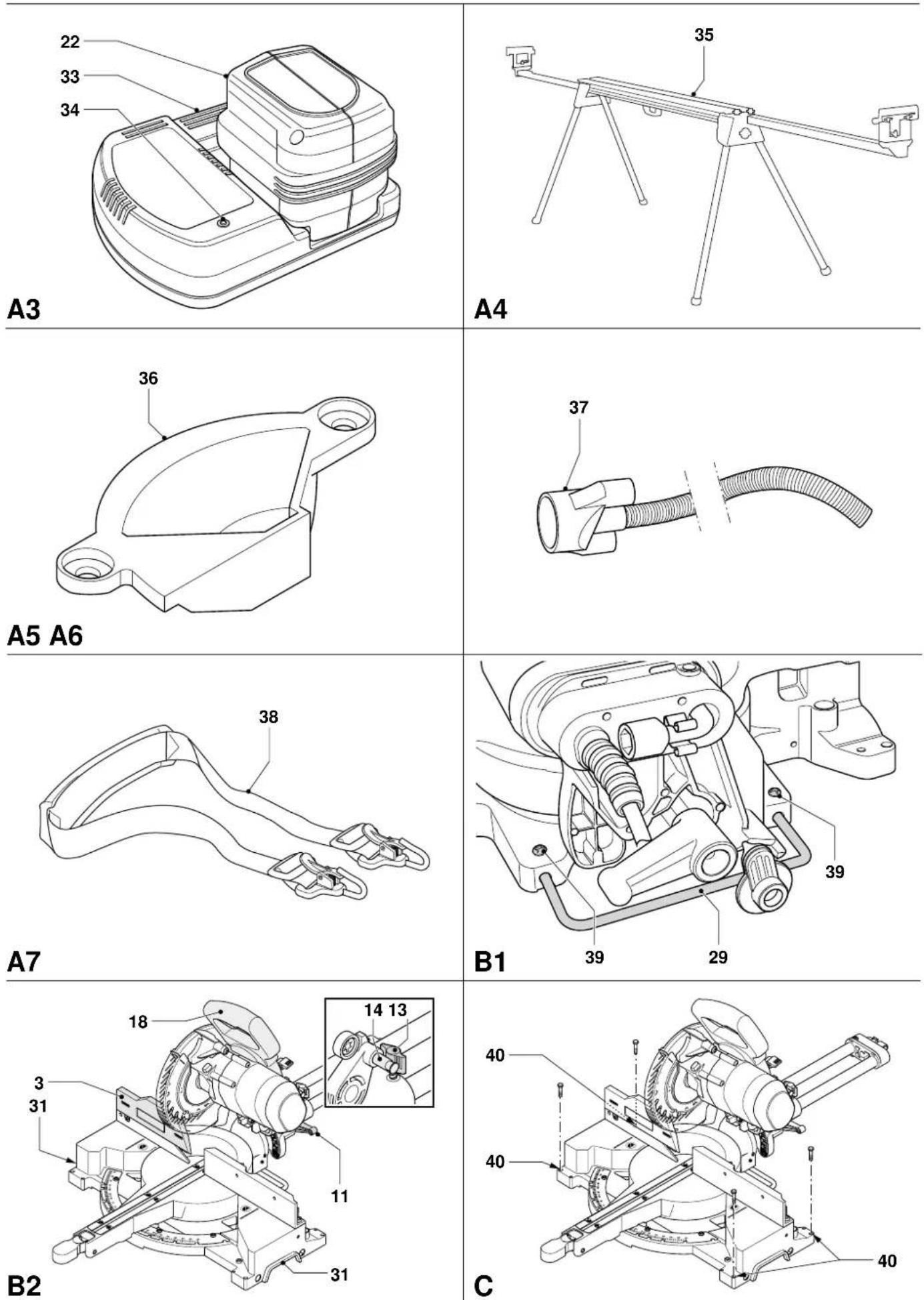
text_image
Technical diagram of a camera module with labeled parts 21 and 22, showing internal components and assembly.D1
text_image
Technical diagram of a mechanical component with labeled parts 22 and 41, showing internal structure and assembly.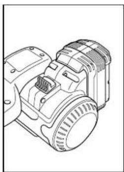
natural_image
Technical line drawing of a mechanical device with no visible text or symbols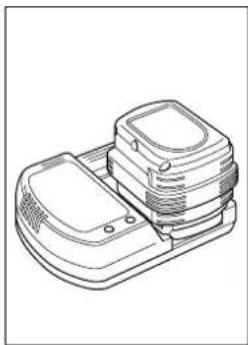
natural_image
Line drawing of a mechanical component with no visible text or symbols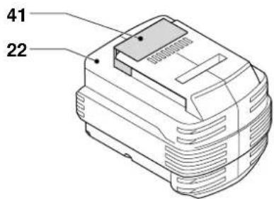
text_image
41 22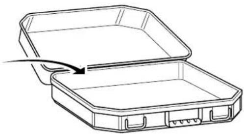
natural_image
Line drawing of an open rectangular container with a curved arrow indicating a motion or force (no text or symbols)D2
text_image
17 2 E1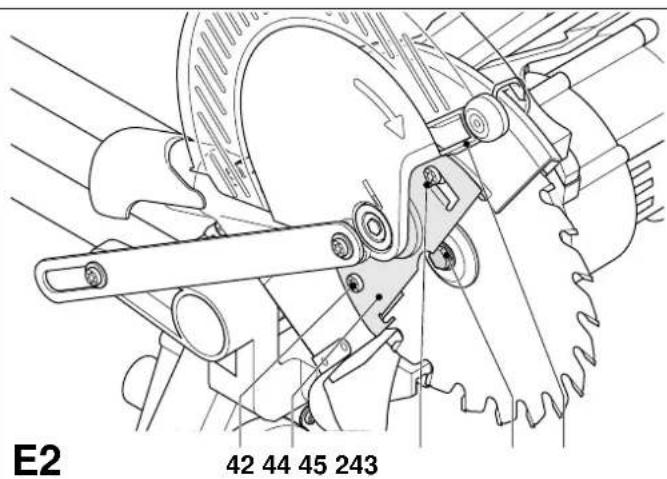
text_image
E2 42 44 45 243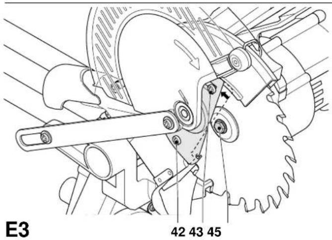
text_image
E3 42 43 45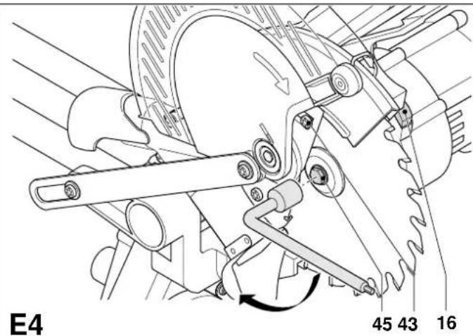
text_image
E4 45 43 16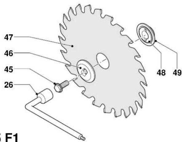
text_image
47 46 45 26 48 49 F1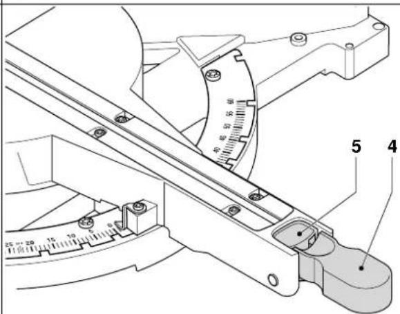
text_image
Technical diagram of a mechanical device with labeled parts and measurement scale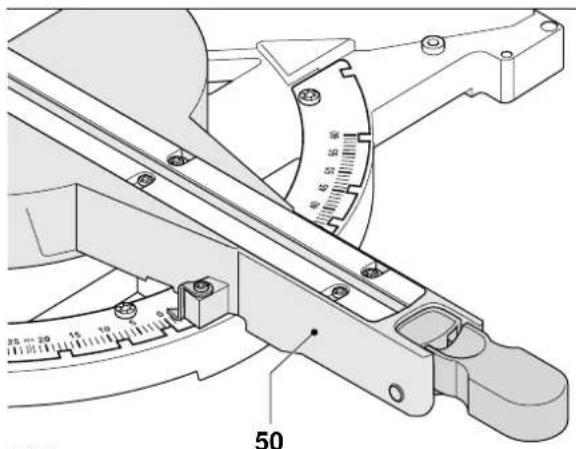
text_image
Technical diagram of a mechanical measuring instrument with labeled parts and scale markings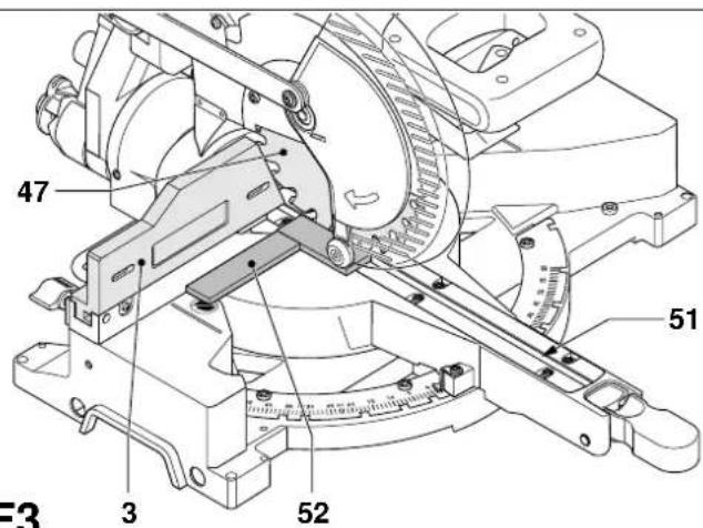
text_image
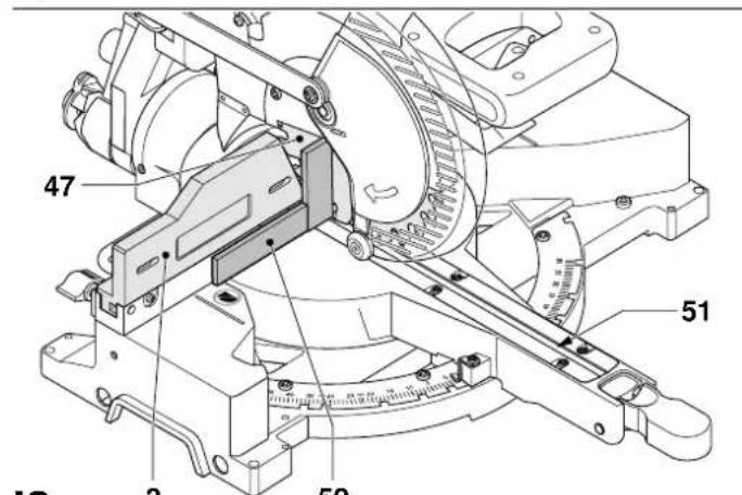
47 51 3 52 F3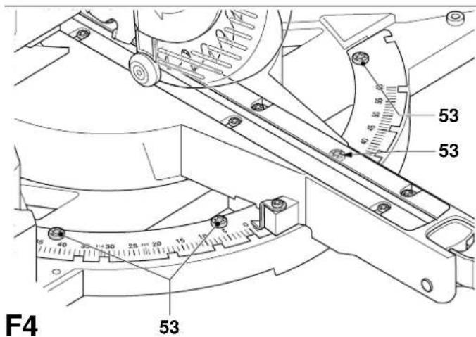
text_image
53 53 F4 53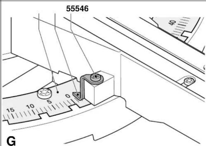
text_image
55546 15 10 5 0 40 G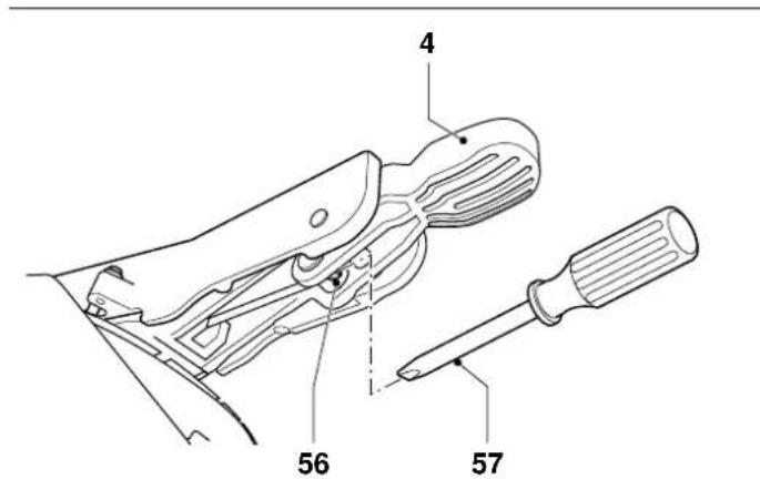
text_image
4 56 57H
natural_image
Technical line drawing of a mechanical assembly with hoses and components (no text or symbols)11
text_image
47 51 2 5212
natural_image
Technical line drawing of a mechanical component with no visible text or symbols13
text_image
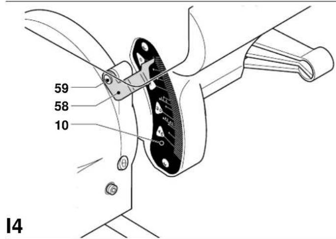
59 58 10 14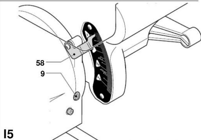
text_image
58 9 15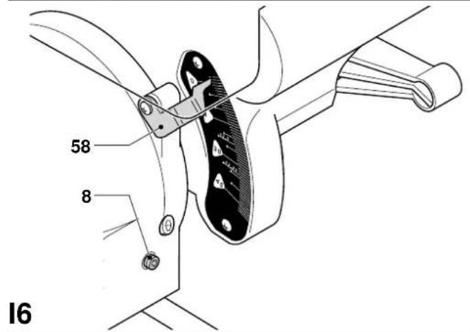
text_image
58 8 16J
text_image
3 30 60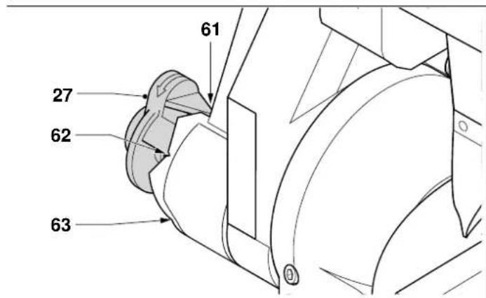
text_image
61 27 62 63K
text_image
64 L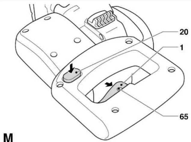
text_image
20 1 65 M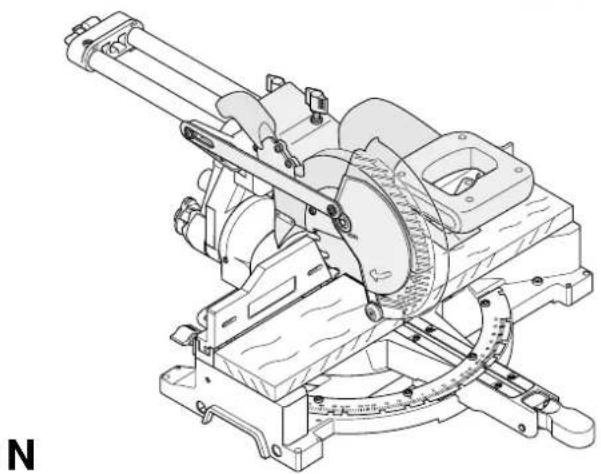
natural_image
Technical line drawing of a mechanical device with gears and levers (no text or symbols)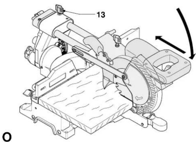
text_image
13 O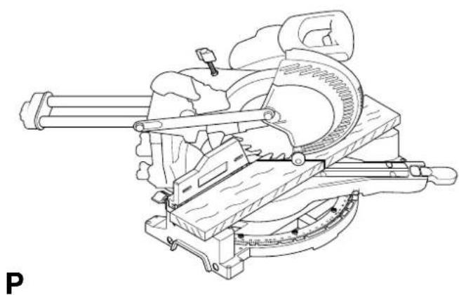
natural_image
Technical line drawing of a mechanical device with no visible text or symbols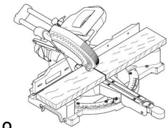
natural_image
Technical line drawing of a mechanical cutting machine with no visible text or symbolsQ
natural_image
Isometric illustration of a wooden plank with visible grain patterns (no text or symbols)R1
 |  |
| R2 | S1 |
 |  |
| S2 | T |
 | |
| U |
GERINGSSAV DW017
Tillykke!
2 Akkus (DW017K2(H))
1 Ladegerät
You have chosen a DEWALT tool. Years of experience, thorough product development and innovation make DEWALT one of the most reliable partners for professional power tool users.
Technical data
| DW017 | ||
| Sound pressure (LpA) dB(A) 88 | ||
| Acoustic power (LwA) dB(A) 101 | ||
| Hand/arm weighted vibration m/s | 2 | < 2.5 |
| Voltage V 24 | ||
| Power output W 630 | ||
| Blade diameter mm 216 | ||
| Blade bore mm 30 | ||
| Max. blade thickness mm 1.6 | ||
| Max. blade speed min | -1 | 4,000 |
| Max. crosscut capacity at 90° mm 300 | ||
| Max. mitre cut capacity at 45° mm 212 | ||
| Max. depth of cut 90° mm 70 | ||
| Max. depth of bevel cross-cut 45° mm 50 | ||
| Mitre (max. positions) | ||
| left 50° | ||
| right | 60° | |
| Bevel (max. positions) | ||
| left 48° | ||
| right | 2° | |
| 0° mitre | ||
| Resulting width at max. height 70 mm | mm 300 | |
| Resulting height at max. width 300 mm | mm 70 | |
| 45° mitre left | ||
| Resulting width at max. height 70 mm | mm 212 | |
| Resulting height at max. width 212 mm | mm 70 | |
| 45° mitre right | ||
| Resulting width at max. height 70 mm | mm 212 | |
| Resulting height at max. width 212 mm | mm 70 | |
| 45° bevel left | ||
| Resulting width at max. height 50 mm | mm 300 | |
| Resulting height at max. width 300 mm | mm 50 | |
| 31.62° mitre, 33.85° bevel | ||
| Resulting height at max. width 254 mm | mm 65 | |
| Automatic blade brake time | s < 5.0 | |
| Dust collection efficiency | mg/m3< 2.0 | |
| Weight | kg 20.5 | |
| Battery pack | DE0242 | DE0241 |
| Battery type | NiCd | NiMH |
| Voltage V 24 | 24 | |
| Weight | kg 1.4 | 1.4 |
| Charger | DE0246 | |
| Mains voltage | VAC230 | |
| Approx. charging time min 60/70 | ||
| Weight | kg 0.6 | |
| Fuses: | ||
| Europe | 230 V tools 10 Amperes, mains | |
| U.K. & Ireland | 230 V tools 13 Amperes, in plugs | |
The following symbols are used throughout this manual:

Denotes risk of personal injury, loss of life or damage to the tool in case of non-observance of the instructions in this manual.

Denotes risk of electric shock.
EC-Declaration of conformity

DW017
DEWALT declares that these power tools have been designed in compliance with: 98/37/EEC, 89/336/EEC, EN 55014-2, EN 55014-1, EN 60335, EN 61000-3-2, EN 61000-3-3, EN 50260-1 & EN 61029.
For more information, please contact DEWALT at the address below or refer to the back of the manual.
Director Engineering and Product Development Horst Großmann
X. fopman
When using stationary power tools, always observe the safety regulations applicable in your country to reduce the risk of fire, electric shock and personal injury.
Read all of this manual carefully before operating the tool.
Save this manual for future reference.
General
1 Keep work area clean
Cluttered areas and benches can cause accidents.
2 Consider work area environment
Do not expose the tool to rain. Do not use the tool in damp or wet conditions. Keep the work area well lit (250 - 300 Lux). Do not use the tool where there is a risk of causing fire or explosion, e.g. in the presence of flammable liquids and gases.
3 Keep children away
Do not allow children, visitors or animals to come near the work area or to touch the tool or the mains cable.
4 Dress properly
Do not wear loose clothing or jewellery, as these can be caught in moving parts. Wear protective hair covering to keep long hair out of the way. When working outdoors, preferably wear suitable gloves and non-slip footwear.
5 Personal protection
Always use safety glasses. Use a face or dust mask whenever the operations may produce dust or flying particles. If these particles might be considerably hot, also wear a heat-resistant apron. Wear ear protection at all times.
6 Guard against electric shock
Prevent body contact with earthed or surfaces (e.g. pipes, radiators, cookers and refrigerators). When using the tool under extreme conditions (e.g. high humidity, when metal swarf is being produced, etc.), electric safety can be improved by inserting an isolating transformer or a (FI) earth-leakage circuit-breaker.
7 Do not overreach
Keep proper footing and balance at all times.
8 Stay alert
Watch what you are doing. Use common sense. Do not operate the tool when you are tired.
9 Secure workpiece
Use clamps or a vice to hold the workpiece. It is safer and it frees both hands to operate the tool.
10 Connect dust extraction equipment
If devices are provided for the connection of dust extraction and collection facilities, ensure that these are connected and properly used.
11 Remove adjusting keys and wrenches
Always check that adjusting keys and wrenches are removed from the tool before operating the tool.
12 Use appropriate tool
The intended use is described in this instruction manual. Do not force small tools or attachments to do the job of a heavy-duty tool. The tool will do the job better and safer at the rate for which it was intended. Do not force the tool.
Warning! The use of any accessory or attachment or performance of any operation with this tool other than those recommended in this instruction manual may present a risk of personal injury.
13 Check for damaged parts
Before use, carefully check the tool and mains cable for damage. Check for misalignment and seizure of moving parts, breakage of parts, damage to guards and switches and any other conditions that may affect its operation. Ensure that the tool will operate properly and perform its intended function. Do not use the tool if any part is damaged or defective.
Do not use the tool if the switch does not turn it on and off. Have any damaged or defective parts replaced by an authorised DEWALT repair agent. Never attempt any repairs yourself.
14 Do not abuse cord
Never pull the cord to disconnect from the socket. Keep the cord away from heat, oil and sharp edges.
15 Remove the battery pack
Switch off and wait for the tool to come to a complete standstill before leaving it unattended. Remove the battery pack when not in use, before changing any parts of the tools, accessories or attachments and before servicing.
16 Avoid unintentional starting
Be sure that the tool is switched off before inserting the battery pack.
17 Store idle tools
When not in use, tools must be stored in a dry place and locked up securely, out of reach of children.
18 Maintain tools with care
Keep the tools in good condition and clean for better and safer performance. Follow the instructions for maintenance and changing accessories. Keep all handles and switches dry, clean and free from oil and grease.
19 Repairs
This tool is in accordance with the relevant safety regulations. Have your tool repaired by an authorised DeWALT repair agent. Repairs should only be carried out by qualified persons using original spare parts; otherwise this may result in considerable danger to the user.
Additional safety rules for mitre saws
- Make sure all locking knobs and clamp handles are tight before starting any operation.
- Do not operate the machine without the guard in position, or if the guard does not function or is not maintained properly.
- Never use your saw without the kerf plate.
- Never place either hand in the blade area when the saw is connected to the electrical power source.
- Never attempt to stop a machine in motion rapidly by jamming a tool or other means against the blade; serious accidents can be caused unintentionally in this way.
- Before using any accessory consult the instruction manual. The improper use of an accessory can cause damage.
- Select the correct blade for the material to be cut.
- Observe the maximum speed marked on the saw blade.
- Use a holder or wear gloves when handling a saw blade.
- Do not use blades of larger or smaller diameter than recommended. For the proper blade rating refer to the technical data. Use only the blades specified in this manual, complying with EN 847-1.
- Consider applying specially designed noise-reduction blades.
- Do not use HSS blades.
- Do not use cracked or damaged saw blades.
- Do not use any abrasive discs.
- Raise the blade from the kerf in the workpiece prior to releasing the switch.
- Ensure that the arm is securely fixed when performing bevel cuts.
- Do not wedge anything against the fan to hold the motor shaft.
- The blade guard on your saw will automatically raise when the arm is brought down; it will lower over the blade when the arm is raised. The guard can be raised by hand when installing or removing saw blades or for inspection of the saw. Never raise the blade guard manually unless the saw is switched off.
- The front section of the guard is louvred for visibility while cutting. Although the louvres dramatically reduce flying debris, there are openings in the guard and safety glasses should be worn at all times when viewing through the louvres.
- Keep the surrounding area of the machine well maintained and free of loose materials, e.g. chips and cut-offs.
- Check periodically that the motor air slots are clean and free of chips.
- Replace the kerf plate when worn.
- Disconnect the machine from the mains before carrying out any maintenance work or when changing the blade.
- Never perform any cleaning or maintenance work when the machine is still running and the head is not in the rest position.
- When possible, always mount the machine to a bench.
Residual risks
The following risks are inherent to the use of saws:
- injuries caused by touching the rotating parts
In spite of the application of the relevant safety regulations and the implementation of safety devices, certain residual risks cannot be avoided. These are:
- Impairment of hearing.
- Risk of accidents caused by the uncovered parts of the rotating saw blade.
- Risk of injury when changing the blade.
- Risk of squeezing fingers when opening the guards.
- Health hazards caused by breathing dust developed when sawing wood, especially oak, beech and MDF.
Additional safety instructions for battery packs

Fire hazard! Avoid metal short circuiting the contacts of a detached battery pack. Do not store or carry the battery pack without the battery cap placed over the contacts.
- The battery fluid, a 25-30% solution of potassium hydroxide, can be harmful. In case of skin contact, flush immediately with water. Neutralize with a mild acid such as lemon juice or vinegar. In case of eye contact, rinse abundantly with clean water for at least 10 minutes. Consult a physician.
- Never attempt to open a battery pack for any reason.
Labels on charger and battery pack
In addition to the pictographs used in this manual, the labels on the charger and the battery pack show the following pictographs:
Battery charging

Battery charged

Problem charging

Charges NiMH and NiCd battery packs

Do not probe with conductive objects

Do not charge damaged battery packs

Read instruction manual before use

Do not expose to water

Have defective cords replaced immediately

Charge only between 4 °C and 40 °C

See technical data for charging time

Always wear safety glasses when plugging in the charger.
Labels on tool
The following pictograms are shown on the tool:

Read the instruction manual before use

Safe use warning

Do not place your hands within this area
Electrical safety
The electric motor has been designed for one voltage only. Always check that the battery pack voltage corresponds to the voltage on the rating plate. Also make sure that the voltage of your charger corresponds to that of your mains.

Your charger is double insulated in accordance with EN 60335.
Mains plug replacement (U.K. & Ireland only)
- Should your mains plug need replacing and you are competent to do this, proceed as instructed below. If you are in doubt, contact an authorized DeWALT repair agent or a qualified electrician.
- Disconnect the plug from the supply.
- Cut off the plug and dispose of it safely; a plug with bared copper conductors is dangerous if engaged in a live socket outlet.
- Only fit 13 Amperes BS1363A approved plugs fitted with the correctly rated fuse (1).
- The cable wire colours, or a letter, will be marked at the connection points of most good quality plugs. Attach the wires to their respective points in the plug (see below). Brown is for Live (L) (2) and Blue is for Neutral (N) (4).
- Before replacing the top cover of the mains plug ensure that the cable restraint (3) is holding the outer sheath of the cable firmly and that the two leads are correctly fixed at the terminal screws.
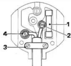
text_image
Technical diagram of a mechanical switch or socket with numbered components labeled 1, 2, 3, and 4.
Never use a light socket.
Never connect the live (L) or neutral (N) wires to the earth pin marked E or 12
Using an extension cable
An extension cord should not be used unless absolutely necessary. Use an approved extension cable suitable for the power input of your charger (see technical data). The minimum conductor size is 1 mm ^2 ; the maximum length is 30 m.
Package contents
The package contains:
1 Assembled mitre saw
1 Blade spanner
1 Saw blade
1 Battery pack (DW017)
2 Battery packs (DW017K2(H))
1 Charger
1 Instruction manual
1 Exploded drawing
- Check for damage to the tool, parts or accessories which may have occurred during transport.
• Take the time to thoroughly read and understand this manual prior to operation.
Description (fig. A1 - A6)
Your DW017 mitre saw has been designed for professional cutting of wood, wood products, aluminium and plastics. It will perform the sawing operations of cross-cutting, bevelling and mitring easily, accurately and safely.
A1
1 On/off switch
2 Moveable lower guard
3 Fence left-hand side
4 Mitre lever
5 Mitre latch
6 Mitre scale
7 Fence right-hand side
8 Intermediate bevel position adjustment stop
9 Bevel position adjustment stop
10 Bevel scale
11 Bevel clamp handle
12 Grooving stop
13 Rail lock knob
14 Head lock down pin
15 Grooving depth adjustment knob
16 Spindle lock button
17 Head lock up release lever
18 Operating handle
20 Lock-off button
21 Battery release button
22 Battery pack
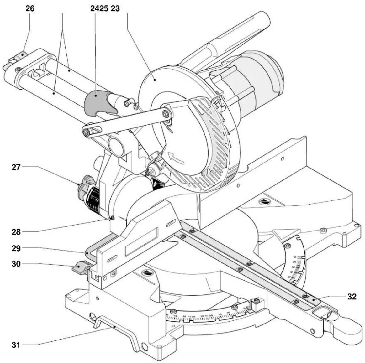
A2
23 Upper guard
24 Dust spout
25 Rails
26 Blade spanner
27 Bevel stop override knob
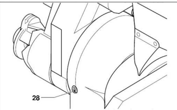
28 Vertical position adjustment stop
29 Base stabiliser
30 Upper fence left-hand side clamping knob
31 Hand indentation
32 Kerf plate
Charger
Your DEWALT charger accepts DEWALT 24 V NiCd and NiMH battery packs.
A3
22 Battery pack
33 Charger
34 Charging indicator (red)
Optional accessories
A4
35 Legstand
A5
36 Fence insert
A6
37 Dust extraction kit
A7
38 Carrying strap
Installation
Unpacking (fig. B1 & B2)
- Remove the saw from the packing material carefully.
- Move the stabiliser (29) in or out until it contacts the work surface. Tighten the screws (39).
- Release the rail lock knob (13), and push the saw head back to lock it in the rear position.
- Press down the operating handle (18) and pull out the lock down pin (14), as shown.
- Gently release the downward pressure and allow the head to rise to its full height.

Never use your saw without the stabiliser.
Bench mounting (fig. C)
- Holes (40) are provided in all four feet to facilitate bench mounting.
Two different sized holes are provided to accommodate different sizes of bolts. Use either hole; it is not necessary to use both. Always mount your saw firmly to prevent movement. To enhance the portability, the tool can be mounted to a piece of 12.5 mm or thicker plywood which can then be clamped to your work support or moved to other job sites and reclamped. - When mounting your saw to a piece of plywood, make sure that the mounting screws do not protrude from the bottom of the wood.
The plywood must sit flush on the work support. When clamping the saw to any work surface, clamp only on the clamping bosses where the mounting screw holes are located. Clamping at any other point will interfere with the proper operation of the saw. - To prevent binding and inaccuracy, be sure the mounting surface is not warped or otherwise uneven. If the saw rocks on the surface, place a thin piece of material under one saw foot until the saw is firm on the mounting surface.
Battery pack (fig. A1, A3, D1 & D2)
Charging the battery pack (fig. A1 & A3)
Always check the mains prior to charging the battery pack. If the mains is functioning but the battery pack does not charge, take your charger to an authorized DeWALT repair agent. Whilst charging, the charger and the battery pack may become warm to touch. This is a normal condition and does not indicate a problem.

Do not charge the battery pack at ambient temperatures < 4 °C
or > 40 °C. Recommended charging temperature: approx. 24 °C.
- To charge the battery pack (20), insert it into the charger (32) as shown and plug in the charger. Be sure that the battery pack is fully seated in the charger. The red charging indicator (33) will blink. After approx. 1 hour, it will stop blinking and remain on. The battery pack is now fully charged.
- The red charging indicator flashes rapidly to indicate a charging problem. Reinsert the battery pack or try a new one. If the new pack also refuses to charge, have your charger tested by an authorised DeWALT repair agent.
Automatic refresh

The automatic refresh mode will equalize or balance the individual cells in the battery pack at its peak capacity. Battery packs should be refreshed overnight after every 10th charge/discharge cycle or whenever the pack no longer delivers the same amount of work.
- To refresh your battery pack, place the battery in the charger as usual. The red light will blink continuously indicating that the charge cycle has started.
- When the 1-hour charge cycle has completed, the light will stay on continuously and will no longer blink. The pack is fully charged and can be used at this time.
- If the pack is left in the charger after the initial 1-hour charge, the charger will automatically initiate the refresh mode. This mode will continue up to 8 hours, but the battery pack can be removed at any time during the refresh mode.
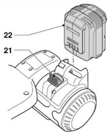
Inserting and removing the battery pack (fig. D1)
- Insert the battery pack into the corresponding slot in the tool until it clicks in place. You may need to use some force to fully engage the spring-loaded mechanism.
• To remove the battery pack, press the release button (21).
We recommend to insert the battery pack into the charger directly after removing it from the tool.
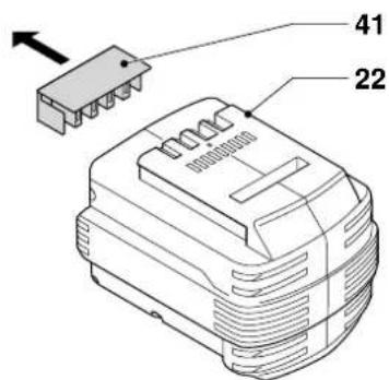
Battery cap (fig. D2)
A protective cap is supplied to cover the contacts of a detached battery pack. Without the protective cap in place, loose metal objects could short circuit the contacts, causing a fire hazard and damaging the battery pack.
• Take off the protective cap (41) before placing the battery pack (22) in the charger or tool.
- Place the protective cap over the contacts immediately after removing the battery pack from the charger or tool.

Make sure the protective cap is in place before storing or carrying a detached battery pack.
AIR COOLED
The charger is equipped with an internal fan for rapid cooling of battery packs. The fan will be automatically switched on when required. The fan will also be switched on periodically when there is no battery in the charger in order to blow dust from the fan vents.

Always wear safety glasses when plugging in the charger.
In order to sustain the life duration of battery packs, we recommend to use air-cooled battery packs only.
Hot/Cold Pack Delay
When the charger detects a battery that is too hot or too cold, it automatically starts a Hot/Cold Pack Delay, suspending charging until the battery has reached an appropriate temperature. The charger then automatically switches to the pack charging mode. This feature ensures maximum battery life. The red indicator blinks long, then short while in the Hot/Cold Pack Delay mode.
Assembly

Prior to assembly, always remove the battery pack.
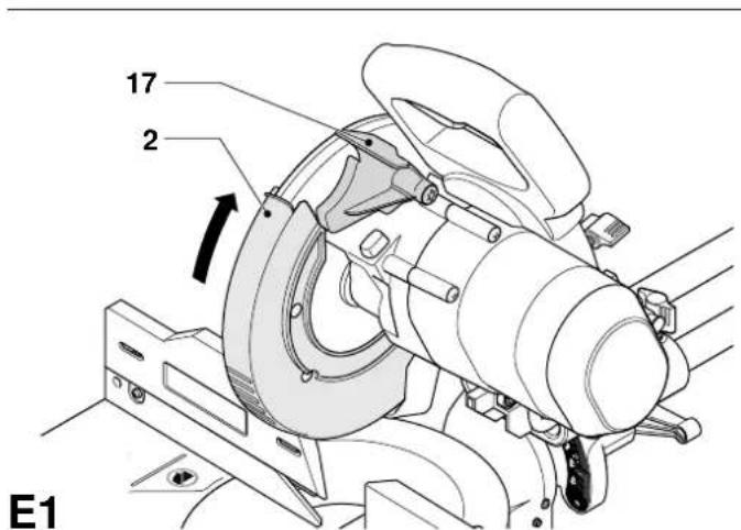
Mounting the saw blade (fig. E1 - E5)
- Depress the head lock up release lever (17) to release the lower guard (2), then raise the lower guard as far as possible.
- Loosen the guard bracket screw (43) sufficiently to allow the guard bracket (44) to be raised to permit access to the blade locking screw (45).
- With the lower guard held in the raised position by the guard bracket screw (43) depress the spindle lock button (16) with one hand, then use the supplied blade spanner (26) in the other hand to loosen the left-hand threaded blade screw (45) by turning clockwise.

To use the spindle lock, press the button as shown and rotate the spindle by hand until you feel the lock engage. Continue to hold the lock button in to keep the spindle from turning.
- Remove the blade locking screw (45) and the outside arbor collar (46).
• Install the saw blade (47) onto the shoulder (48) provided on the inside arbor collar (49), making sure that the teeth at the bottom edge of the blade are pointing toward the back of the saw (away from the operator). - Replace the outer arbor collar (46).
- Tighten the blade locking screw (45) by turning counter-clockwise while holding the spindle lock engaged with your other hand.
- Move the guard bracket (44) down so that it fully screens the blade locking screw (45).
- Tighten the guard bracket screw (43).

- Never press the spindle lock while the blade is rotating.
- Be sure to hold the guard bracket down and firmly tighten the guard bracket screws after installing the blade.
Adjustment

Prior to adjustment always remove the battery pack.
Your mitre saw was accurately adjusted at the factory. If readjustment due to shipping and handling or any other reason is required, follow the steps below to adjust your saw. Once made, these adjustments should remain accurate.
Checking and adjusting the blade to the fence (fig. F1 - F4)
- Release the mitre lever (4) and depress the mitre latch (5) to release the mitre arm (50).
- Swing the mitre arm until the latch locates it at the 0^ mitre position. Do not tighten the lever.
- Pull down the head until the blade just enters the saw kerf (51).
- Place a square (52) against the left side (7) of the fence and blade (47) (fig. F3).

Do not touch the tips of the blade teeth with the square.
- If adjustment is required, proceed as follows:
- Loosen the screws (53) and move the scale/mitre arm assembly left or right until the blade is at 90^ to the fence as measured with the square.
- Retighten the screws (53). Pay no attention to the reading of the mitre pointer at this point.
Adjusting the mitre pointer (fig. F1, F2 & G)
- Release the mitre lever (4) and depress the mitre latch (5) to release the mitre arm (50).
- Move the mitre arm to set the mitre pointer (54) to the zero position, as shown in fig. G.
- With the mitre lever loose, allow the mitre latch to snap into place as you rotate the mitre arm past zero.
- Observe the pointer (54) and mitre scale (6). If the pointer does not indicate exactly zero, loosen the screw (55), move the pointer to read 0^ and tighten the screw.
Mitre lock/detent rod adjustment (fig. H)
If the base of the saw can be moved while the mitre lever (4) is locked, the mitre lock/detent rod (56) must be adjusted.
- Unlock the mitre lever (4).
- Fully tighten the mitre lock/detent rod (56) using a screwdriver (57). Then loosen the rod a quarter of a turn.
- Check that the table does not move when the lever (4) is locked at a random (not preset) angle.
Checking and adjusting the blade to the table (fig. 11 - 14)
- Loosen the bevel clamp handle (11).
- Press the saw head to the right to ensure it is fully vertical and tighten the bevel clamp handle.
- Pull down the head until the blade just enters the saw kerf (51).
- Place a set square (52) on the table and up against the blade (47) (fig. 12).

Do not touch the tips of the blade teeth with the square.
- If adjustment is required, proceed as follows:
- Loosen the bevel clamp handle (11) and turn the vertical position adjustment stop screw (28) in or out until the blade is at 90^ to the table as measured with the square.
- If the bevel pointer (58) does not indicate zero on the bevel scale (10), loosen the screw (59) that secures the pointer and move the pointer as necessary.
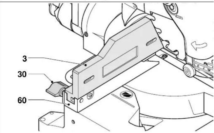
Adjusting the fence (fig. J)
The upper part of the left side of the fence can be adjusted to the left to provide clearance, allowing the saw to bevel to a full 48^ left. To adjust the fence (3):
- Loosen the plastic knob (30) and slide the fence to the left.
- Make a dry run with the saw switched off and check for clearance. Adjust the fence to be as close to the blade as practical to provide maximum workpiece support, without interfering with the up and down movement of the arm.
- Tighten the knob securely.

The guide groove (60) can become clogged with sawdust. Use a stick or some low pressure air to clear the guide groove.
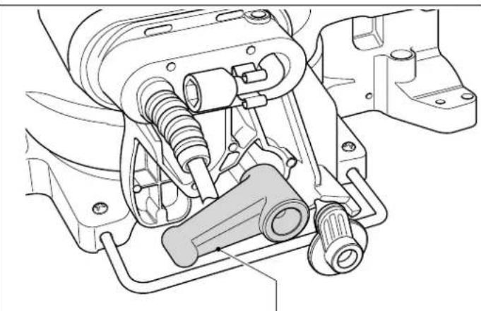
Overriding the bevel stops (fig. K)
The bevel stops facilitate the setting of the saw blade in the vertical position and the 45^ bevel position. By overriding the bevel stops, bevel angles can be achieved from 2^ right to 48^ left.
- To override the bevel stops, first release the saw head and push it slightly to the left, then pull out the override knob (27) and turn it into the override position (62). The override knob automatically clicks in place.
- Set the required bevel angle and secure the head in this position.
- To discontinue the override, turn the override knob (27) back into the bevel stop position (61).
Intermediate bevel stop
The intermediate bevel angle is preset at 33.85^ , enabling a quick setting for the cutting of crown moulding.
- To activate the intermediate bevel stop, turn the override knob (27) into the intermediate bevel stop position (63).
Checking and adjusting the bevel angle (fig. A1, A2 & I5)
- Make sure the override knob (27) is located in the bevel stop position.
- Loosen the left side fence clamping knob (30) and slide the upper part of the left side fence to the left as far as it will go.
- Loosen the bevel clamp handle (11) and move the saw head to the left. This is the 45^ bevel position.
- If adjustment is required, proceed as follows:
- Turn the stopscrew (9) in or out as necessary until the pointer (58) indicates 45^ .
Checking and adjusting the intermediate bevel angle (fig. A1, A2, & I6)
- Make sure the override knob (27) is located in the intermediate bevel stop position.
- Loosen the left side fence clamping knob (30) and slide the upper part of the left side fence to the left as far as it will go.
- Loosen the bevel clamp handle (11) and move the saw head to the left. This is the 33.85^ bevel position.
- If adjustment is required, proceed as follows:
- Turn the stopscrew (8) in or out as necessary until the pointer (58) indicates 33.85^ .
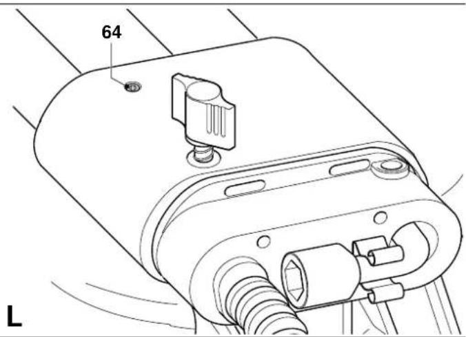
Rail guide adjustment (fig. L)
- Regularly check the rails for clearance.
- To reduce clearance, gradually rotate the set screw (64) clockwise while sliding the saw head back and forth.
Instructions for use

- Always observe the safety instructions and applicable regulations.
The attention of UK users is drawn to the “woodworking machines regulations 1974” and any subsequent amendments.
Prior to operation:
• Install the appropriate saw blade. Do not use excessively worn blades. The maximum rotation speed of the tool must not exceed that of the saw blade.
- Do not attempt to cut excessively small pieces.
- Allow the blade to cut freely. Do not force.
- Allow the motor to reach full speed before cutting.
- Make sure all locking knobs and clamp handles are tight.
- Secure the workpiece.
- Although this saw will cut wood and many nonferrous materials, these operating instructions refer to the cutting of wood only. The same guide-lines apply to the other materials. Do not cut ferrous (iron and steel) materials, fibre cement or masonry with this saw!
- Make sure to use the kerf plate. Do not operate the machine if the kerf slot is wider than 10 mm.
Switching on and off (fig. M)
A hole (65) is provided in the trigger for insertion of a padlock to lock the tool.
- To run the tool, depress the lock-off button (20) and subsequently press the on/off switch (1).
- Release the lock-off button (20).
• To stop the tool, release the switch.
Basic saw cuts
Vertical straight cross cut, (fig. A1, A2 & N)
- Release the mitre lever (4) and depress the mitre latch (5).
- Engage the mitre latch at the 0^ position and tighten the mitre lever.
- Place the wood to be cut against the fence (3 & 7).
-
Take hold of the operating handle (18) and depress the head lock up release lever (17) to release the head. Press the trigger switch (1) to start the motor.
-
Depress the head to allow the blade to cut through the timber and enter the plastic kerf plate (32).
- After completing the cut, release the switch and wait for the saw blade to come to a complete standstill before returning the head to its upper rest position.
Performing a sliding cut (fig. O)
The guide rail allows cutting larger workpieces from 50 x 100 mm up to 500 x 1000 mm using an out-down-back sliding motion.
- Release the rail lock knob (13).
- Pull the saw head towards you and switch the tool on.
- Lower the saw blade into the workpiece and push the head back to complete the cut.
• Proceed as described above.

- Do not perform sliding cuts on workpieces smaller than 50 × 100 ~mm .
- Remember to lock the saw head in the rear position when the sliding cuts are finished.
Vertical mitre cross-cut (fig. A1, A2 & P)
- Release the mitre lever (4) and depress the mitre latch (5). Move the arm left or right to the required angle.
- The mitre latch will automatically locate at 10^ , 15^ , 22.5^ , 31.62^ and 45^ both left and right, and at 50^ left and 60^ right. If any intermediate angle is required hold the head firmly and lock by tightening the mitre lever.
• Always ensure that the mitre lever is locked tightly before cutting. - Proceed as for a vertical straight cross-cut.

When mitring the end of a piece of wood with a small off-cut, position the wood to ensure that the off-cut is to the side of the blade with the greater angle to the fence; i.e. left mitre, off-cut to the right - right mitre, off-cut to the left.
Bevel cuts (fig. A1, A2 & Q)
Bevel angles can be set from 48^ left to 2^ right and can be cut with the mitre arm set between zero and a maximum of 45^ mitre position right or left.
- Loosen the left side fence clamping knob (30) and slide the upper part of the left side fence (3) to the left as far as it will go. Loosen the bevel clamp handle (11) and set the bevel as desired.
- Tighten the bevel clamp handle (11) firmly.
• Proceed as for a vertical straight cross-cut.
Quality of cut
The smoothness of any cut depends on a number of variables, e.g. the material being cut. When smoothest cuts are desired for moulding and other precision work, a sharp (60 tooth carbide) blade and a slower, even cutting rate will produce the desired results.

Ensure that the material does not creep while cutting; clamp it securely in place. Always let the blade come to a full stop before raising the arm. If small fibres of wood still split out at the rear of the workpiece, stick a piece of masking tape on the wood where the cut will be made. Saw through the tape and carefully remove tape when finished.
Body and hand position
Proper positioning of your body and hands when operating the mitre saw will make cutting easier, more accurate and safer.
- Never place your hands near the cutting area.
- Place your hands no closer than 150 mm from the blade.
-
Hold the workpiece tightly to the table and the fence when cutting. Keep your hands in position until the switch has been released and the blade has completely stopped.
-
Always make dry runs (without power) before finish cuts so that you can check the path of the blade.
- Do not cross your hands.
- Keep both feet firmly on the floor and maintain proper balance.
- As you move the saw arm left and right, follow it and stand slightly to the side of the saw blade.
- Sight through the guard louvres when following a pencil line.
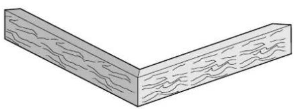
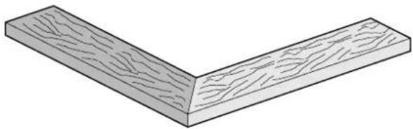
Cutting picture frames, shadow boxes & other four sided projects (fig. R1 & R2)
Trim moulding and other frames
Try a few simple projects using scrap wood until you develop a "feel" for your saw. Your saw is the perfect tool for mitring corners like the one shown in fig. R1. The joint shown has been made using either bevel adjustment.
- Using bevel adjustment
The bevel for the two boards is adjusted to 45^ each, producing a 90^ corner. The mitre arm is locked in the zero position. The wood is positioned with the broad flat side against the table and the narrow edge against the fence.
- Using mitre adjustment
The same cut can be made by mitring right and left with the broad surface against the fence.
The two sketches (fig. R1 & R2) are for four side objects only. As the number of sides changes, so do the mitre and bevel angles. The chart below gives the proper angles for a variety of shapes, assuming that all sides are of equal length. For a shape that is not shown in the chart, divide 180^ by the number of sides to determine the mitre or bevel angle.
| No. of sides Angle mitre or bevel |
| 4 45° |
| 5 36° |
| 6 30° |
| 7 25.7° |
| 8 22.5° |
| 9 20° |
| 10 18° |
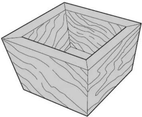
Compound mitre (fig. S1 & S2)
A compound mitre is a cut made using a mitre angle (fig. R2) and a bevel angle (fig. R1) at the same time. This is the type of cut used to make frames or boxes with slanting sides like the one shown in fig. S1.

If the cutting angle varies from cut to cut, check that the bevel clamp knob and the mitre lock knob are securely tightened. These knobs must be tightened after making any changes in bevel or mitre.
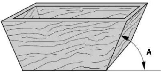
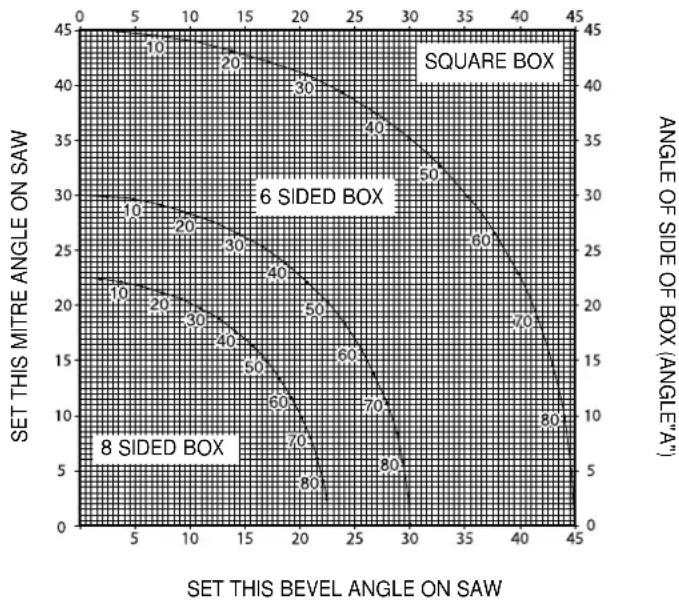
- The chart shown below will assist you in selecting the proper bevel and mitre settings for common compound mitre cuts. To use the chart, select the desired angle "A" (fig. S2) of your project and locate that angle on the appropriate arc in the chart. From that point follow the chart straight down to find the correct bevel angle and straight across to find the correct mitre angle.
- Set your saw to the prescribed angles and make a few trial cuts.
• Practice fitting the cut pieces together. - Example: To make a 4 sided box with 25^ exterior angles (angle "A") (fig. S2), use the upper right arc. Find 25^ on the arc scale. Follow the horizontal intersecting line to either side to get the mitre angle setting on the saw (23^) .
Likewise follow the vertical intersecting line to the top or bottom to get the bevel angle setting on the saw (40°). Always try cuts on a few scrap pieces of wood to verify the settings on the saw.
Cutting base mouldings
The cutting of base moulding is performed at a 45° bevel angle.
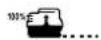
• Always make a dry run without power before making any cuts.
- All cuts are made with the back of the moulding laying flat on the saw.
Inside corner
- Left side
- Position the moulding with top of the moulding against the fence.
- Save the left side of the cut.
- Right side
- Position the moulding with the bottom of the moulding against the fence.
- Save the left side of the cut.
Outside corner
- Left side
- Position the moulding with the bottom of the moulding against the fence.
- Save the right side of the cut.
- Right side
- Position the moulding with top of the moulding against the fence.
- Save the right side of the cut.
Cutting crown mouldings
The cutting of crown moulding is performed in a compound mitre. In order to achieve extreme accuracy, your saw has pre-set angle positions at 31.62^ mitre and 33.85^ bevel. These settings are for standard crown mouldings with 52^ angles at the top and 38^ angles at the bottom.
- Make test cuts using scrap material before doing the final cuts.
- All cuts are made in a left bevel and with the back of the moulding against the base.
Inside corner
- Left side
- Top of the moulding against the fence.
- Mitre right.
- Save the left side of the cut.
- Right side
- Bottom of the moulding against the fence.
- Mitre left.
- Save the left side of the cut.
Outside corner
- Left side
- Bottom of the moulding against the fence.
- Mitre left.
- Save the right side of the cut.
- Right side
- Top of the moulding against the fence.
- Mitre right.
- Save the right side of the cut.
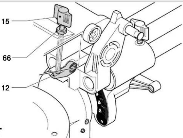
Grooving (fig. T)
Your saw is equipped with a grooving stop (12) and thumbscrew (15) to allow for groove cutting.
- Flip the grooving stop (12) towards the front of the saw.
- Adjust the thumbscrew (15) to set the depth of the groove cut. It might be necessary to release the lock nut (66) first.
scatter
| SET THIS BEVEL ANGLE ON SAW | SET THIS MITRE ANGLE ON SAW | ANGLE OF SIDE OF BOX (ANGLE"A") | | :--- | :--- | :--- | | 5 | 23 | 10 | | 7 | 22 | 10 | | 9 | 20 | 20 | | 11 | 19 | 20 | | 13 | 18 | 30 | | 15 | 17 | 30 | | 17 | 16 | 40 | | 19 | 15 | 40 | | 21 | 14 | 50 | | 23 | 13 | 50 | | 25 | 12 | 60 | | 27 | 11 | 70 | | 29 | 10 | 80 | | 31 | 9 | 80 | | 33 | 8 | 70 | | 35 | 7 | 60 | | 37 | 6 | 50 | | 39 | 5 | 40 | | 41 | 4 | 30 | | 43 | 3 | 20 | | 45 | 2 | 10 | SQUARE BOX; 6 SIDED BOX; 8 SIDED BOX; ANGLE OF SIDE OF BOX (ANGLE"A").- Place a piece of scrap material of approx. 5 cm between fence and workpiece in order to perform a straight groove cut.
Dust extraction (fig. A2 & A6)
This machine is provided with a dust extraction point (24) for connection of a dust extraction kit (37) (available as an option).
- Whenever possible, connect a dust extraction device designed in accordance with the relevant regulations regarding dust emission.
Cutting small pieces (fig. A5)
The fence insert (36) (available as an option) will increase the ease of cutting small pieces.
Support for long pieces (fig. A4)
• Always support long pieces.
- For best results, use the extension work support (35) to extend the table width of your saw (available from your dealer as an option). Support long workpieces using any convenient means such as saw-horses or similar devices to keep the ends from dropping.
Saw blades
To obtain the stated cutting capacities, always use 216 mm saw blades with 30 mm arbor holes.
Applying special saw blades with increased number of teeth or increased body thickness will decrease the number of cuts per battery charge.
Consult your dealer for further information on the appropriate accessories.
Transporting (fig. B2)
In order to conveniently carry the tool, a carrying strap can be attached to the base. The carrying strap (see fig. A7) is available as an option.
- To transport the saw, lower the head and depress the lock down pin (14).
- Lock the rail lock knob with the saw head in the front position, lock the mitre arm in the utter right mitre angle, slide the fence (3) completely inward and lock the bevel lever (11) with the saw head in the vertical position to make the tool as compact as possible.
• Always use the hand indentations (31) shown in fig. B2 to transport the saw.
Maintenance
Your DEWALT Power Tool has been designed to operate over a long period of time with a minimum of maintenance. Continuous satisfactory operation depends upon proper tool care and regular cleaning.

Cleaning
Keep the ventilation slots clear and regularly clean the housing with a soft cloth.
- Unplug the charger before cleaning the housing with a soft cloth.
- Remove the battery pack before cleaning your power tool.
• Regularly clean the table top.
• Regularly clean the dust collection system.

Avoid the use of cleaners or lubricants to maintain the tool. In particular spray and aerosol cleaners may chemically attack the plastic lower guard.
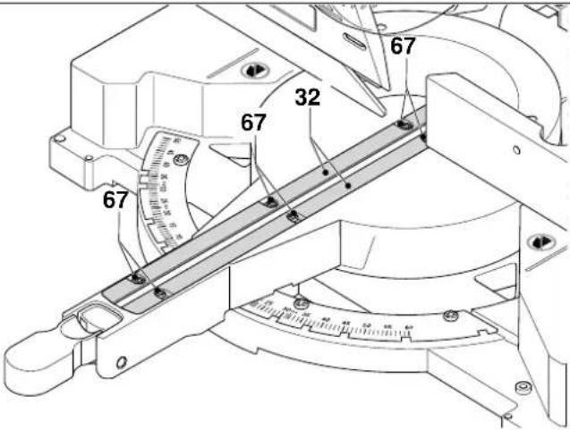
Cleaning and maintaining the kerf plate (fig. U)
Regularly clean the area below the kerf plate.
If the kerf plate is worn it must be replaced.
- Remove the screws (67) holding the kerf plate (32).
- Remove the kerf plate and clean the area below.
- Re-install the parts of the kerf plate and the screws.
• Tighten the screws hand-tight.
• To adjust the kerf plate, proceed as follows: - Pull down the head until the blade just enters the saw kerf.
- Adjust each part of the kerf plate to fit closely to the teeth of the blade.
- Tighten the screws.
Environment

Rechargeable battery pack
This long life battery pack must be recharged when it fails to produce sufficient power on jobs which were easily done before. At the end of its technical life, discard it with due care for our environment:
- Run the battery pack down completely, then remove it from the tool.
- NiCd and NiMH cells are recyclable. Take them to your dealer or a local recycling station. The collected battery packs will be recycled or disposed of properly.

Unwanted tools
Take your tool to an authorised DEWALT repair agent where it will be disposed of in an environmentally safe way.
GUARANTEE
• 30 DAY NO RISK SATISFACTION GUARANTEE •
If you are not completely satisfied with the performance of your DEWALT machine, simply return it within 30 days, complete as purchased, to the point of purchase, for a full refund or exchange. Proof of purchase must be produced.
• ONE YEAR FREE SERVICE CONTRACT •
If you need maintenance or service for your DEWALT machine, in the 12 months following purchase, it will be undertaken free of charge at an authorized DEWALT repair agent. Proof of purchase must be produced. Includes labour and spare parts for Power Tools. Excludes accessories.
• ONE YEAR WARRANTY •
If your DEWALT product becomes defective due to faulty materials or workmanship within 12 months from the date of purchase, we guarantee to replace all defective parts free of charge or, at our discretion, replace the unit free of charge provided that:
• The product has not been misused.
• Repairs have not been attempted by unauthorized persons.
• Proof of purchase date is produced.
This guarantee is offered as an extra benefit and is additional to consumers statutory rights.
For the location of your nearest authorized DEWALT repair agent, please use the appropriate telephone number on the back of this manual. Alternatively, a list of authorized DEWALT repair agents and full details on our after-sales service are available on the Internet at www.2helpU.com.
INGLETADORA DW017
¡Enhorabuena!
Director Engineering and Product Development Horst Großmann
X. fopman
14 Retirer le pack-batteries
Pack-batteries chargé

L'emballage contient:
Pack-batteries (fig. A1, A3, D1 & D2)
Chargement du pack-batteries (fig. A1 & A3)
Packs-batteries rechargeables
Director Engineering and Product Development Horst Großmann

text_image
X. JopmanDEWALT, Richard-Klinger-Straße 40, D-65510, Idstein, Duitsland
3 Parallelgeleiding links
4 Verstekhendel
5 Verstekgrendel
6 Verstekschaal
Director Engineering and Product Development Horst Großmann
X. fopman
DEWALT, Richard-Klinger-Straße 40, D-65510, Idstein, Tyskland
2 Batteripakker (DW017K2(H))
line
| INNSTILL DENNE AVFASINGSVINKELEN PÅ SAGEN | INNSTILL DENNE GJÆRINGSVINKELEN PÅ SAGEN | VINKEL PÅ KASSENS SIDE (VINKEL "A") | |---|---|---| | 5 | 20 | 10 | | 10 | 20 | 20 | | 15 | 30 | 30 | | 20 | 40 | 40 | | 25 | 30 | 35 | | 30 | 20 | 30 | | 35 | 10 | 25 | | 40 | 5 | 20 | | 45 | 0 | 15 | | 5 | 10 | 10 | | 10 | 15 | 20 | | 15 | 20 | 30 | | 20 | 25 | 40 | | 25 | 30 | 50 | | 30 | 35 | 60 | | 35 | 40 | 70 | | 40 | 45 | 80 | The chart displays a contour line labeled 'KVADRATISK KASSE' and '6-SIDET KASSE' above it, with contour lines numbered from 10 to 80 indicating discrete levels of an unspecified variable. The x-axis represents the average AVFASINGSVINKEL på sagen, and the y-axis represents the average gjæringsVINKEL på sagen. The data points are grouped into three distinct regions: '8-SIDET KASSE', '6-SIDET KASSE', and 'KVADRATISK KASSE'.Director Engineering and Product Development Horst Großmann
X. fopsman
DEWALT, Richard-Klinger-Straße 40, D-65510, Idstein, Alemanha
11 Retire as chaves de ajuste
1 Interruptor on/off
Director Engineering and Product Development Horst Großmann
X. fopman
Director Engineering and Product Development Horst Großmann
X. fopman
DEWALT, Richard-Klinger-Straße 40, D-65510, Idstein, Tyskland