
LST 1503 VR - Drill Flex - Free user manual and instructions
Find the device manual for free LST 1503 VR Flex in PDF.

| Product Type | Stick Drill / Professional Surface Finisher |
| Brand | Flex |
| Model | LST 1503 VR |
| Intended Use | Roughening and milling of stone surfaces, professional use in industry and crafts |
| Adjustable Working Width | 40 to 92 mm |
| No-load Speed | 800 to 2400 rpm |
| Input Power | 1200 W |
| Output Power | 700 W |
| Tool Holder | M14 |
| Weight (without cable) | 5.9 kg |
| Protection Class | II (double insulation) |
| Power Cable Length | 4.0 m |
| Sound Pressure Level (LpA) | 87 dB(A) (uncertainty K=3 dB) |
| Sound Power Level (LwA) | 98 dB(A) (uncertainty K=3 dB) |
| Vibration Value (granite surfacing) | aₕ = 6.2 m/s² (uncertainty K=1.5 m/s²) |
| Vacuum System | Connection for vacuum nozzle (standard 32/36 mm) |
| Safety Device | Overload circuit breaker, automatic shut-off in case of brush wear |
| Switch Type | Rocker switch with lock-on function |
| Speed Adjustment | Preset dial (levels 1 to 6, max working level 3 recommended) |
| Delivery Contents | Vacuum hose, mountable stop, hard metal rollers, support bearings |
| Maintenance | Regular cleaning of ventilation slots, replacement of carbon brushes with original parts |
| Conformity | CE, EN 60745, directives 2006/42/EC, 2014/30/EU, 2011/65/EU |
| Warranty | See manufacturer's conditions (www.flex-tools.com) |
Frequently Asked Questions - LST 1503 VR Flex
User questions about LST 1503 VR Flex
0 question about this device. Answer the ones you know or ask your own.
Ask a new question about this device
Download the instructions for your Drill in PDF format for free! Find your manual LST 1503 VR - Flex and take your electronic device back in hand. On this page are published all the documents necessary for the use of your device. LST 1503 VR by Flex.
USER MANUAL LST 1503 VR Flex
- Gerät einschalten.
Manager Research & Development (R & D)
Klaus Peter WeinperEckhard F Head of Quality Department (QD)
29.05.2015
Symbols used in this manual ..... 13
Technical specifications ..... 13
Overview 14
For your safety 15
Noise and vibration 17
Operating instructions 18
Operating instructions 20
Maintenance and care 20
Disposal information 21
C€-Declaration of Conformity .....21
Exemption from liability 21
Symbols used in this manual

WARNING!
Denotes impending danger. Non-observance of this warning may result in death or extremely severe injuries.

CAUTION!
Denotes a possibly dangerous situation.
Non-observance of this warning may result insight injury or damage to property.

NOTE
Denotes application tips and important information.
Symbols on the power tool

Before switching on the power tool, read the operating manual!

Wear goggles!

Disposal information for the old machine (see page 21)!
Technical specifications
| Machine type | Bush hammering machineLST 803 VR LST 1503 VR | ||
| Working width mm 55–130 40–92 | |||
| Idling speed r.p.m. 800–2400 800–2400 | |||
| Power input W | 1800 | 1200 | |
| Power output | W | 1200 | 700 |
| Tool holder | M14 | M14 | |
| Weight (without power cord) | kg | 7.2 | 5.9 |
| Protection class | II/☐ | II/☐ | |
Overview
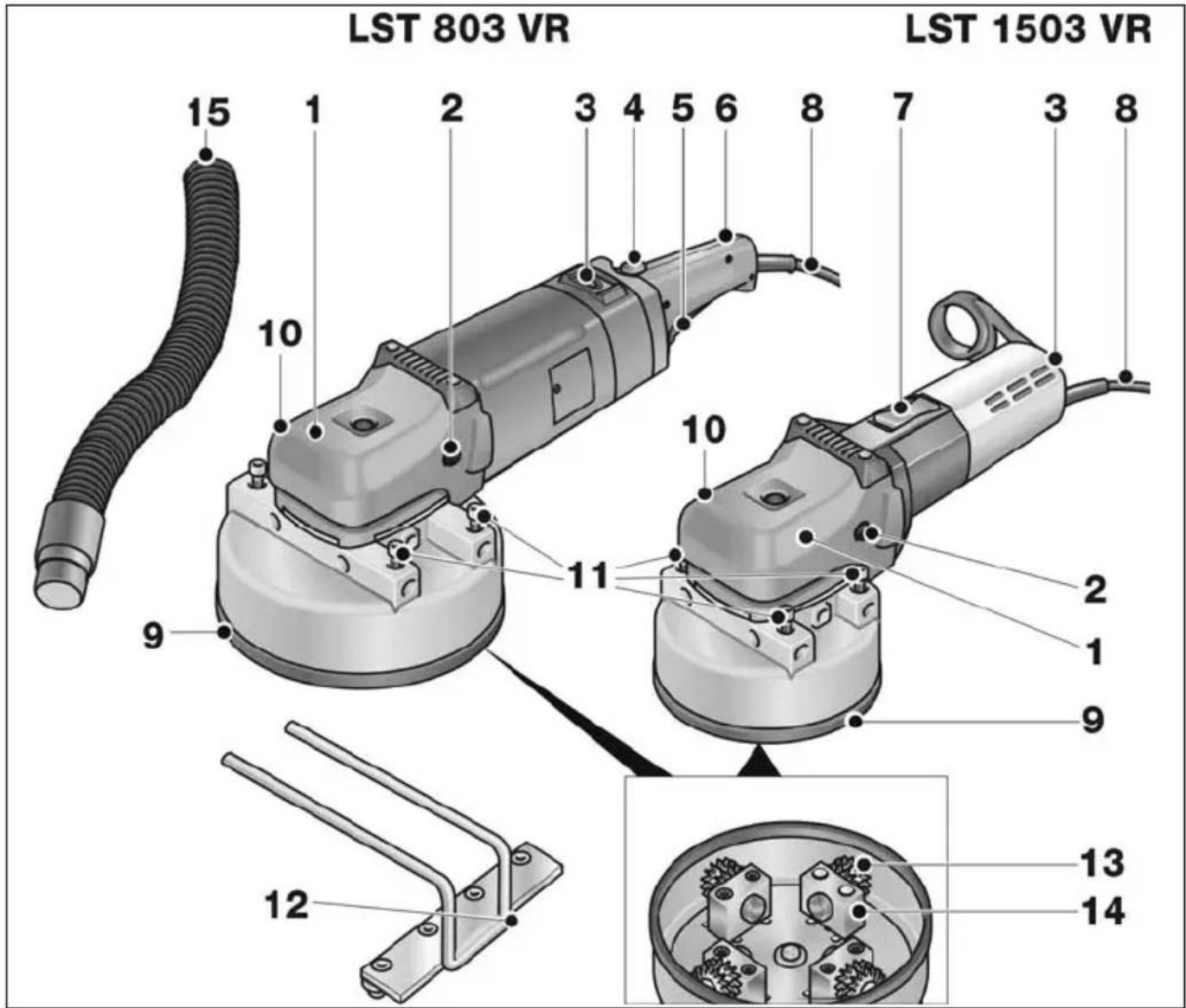
1 Gear head with handle cover
With air outlet and direction-of-rotation arrow.
2 Fastening screw for handle cover
3 Dial for preselecting the speed
4 Starting lockout (LST 803 VR only)
5 S w(LSTi803 VR only) h
Switches the power tool on and off.
6 S t e (LSTm803 VR onl
7 Switch rocker (LST 1503 VR only)
For switching on and off.
With notched position for continuous operation.
8 4.0 m power cord with plug
9 Milling head
10 Connector for dust extractor
11 Fastening screws for attachable stop
12 Attachable stop
13 Carbide wheels
14 Bearing blocks
d 15 \$uction hose
For your safety

WARNING!
Before using the power tool, please read and follow:
– these operating instructions,
- the "General safety instructions" onthehandling of power tools in the enclosedbooklet (leaflet-no.: 315.915),
– the currently valid site rules and the regulations for the prevention of accidents.
This power tool is state of the art and has been constructed in accordance with the acknowledged safety regulations.
Nevertheless, when in use, the power tool may be a danger to life and limb of the user or a third party, or the power tool or other property may be damaged.
The power tool may be operated only if it is
- as intended,
– in perfect working order.
Faults which impair safety must be repaired immediately.
Intended use
This bush hammering machine is designed
– for commercial use in industry and trade,
– for roughening and milling stone surfaces with tools which are offered by the manufacturer for this power tool,
- for use on staircases and surfaces.
Safety instructions for bush hammering machines

WARNING!
Read all safety instructions and other instructions. Failure to observe the safety instructions and other instructions may result in an electric shock, fire and/or serious injuries. Keep all safety instructions and other instructions in a safe place for the future.
■ This electric power tool must be used with the appropriate accessories as a refurbishing milling machine.
Read all safety warnings, instructions, illustrations and specifications provided with this power tool.
Failure to follow all instructions listed below may result in electric shock, fire and/or serious injury.
■ This electric power tool is not suitable for use with wire brushes, or for polishing, sanding with sandpaper, renovation sanding or cut-off grinding.
Operations for which the power tool was not designed may create a hazard and cause personal injury.
■ Do not use accessories which are not specifically designed and recommended by the tool manufacturer.
Just because the accessory can be attached to your power tool, it does not assure safe operation.
■ The rated speed of the accessory must be at least equal to the maximum speed marked on the power tool.
Accessories running faster than their rated speed can break and fly apart.
■ The outside diameter and the thickness of your accessory must be within the capacity rating of your power tool. Incorrectly measured insertion tools cannot be adequately shielded or controlled.
■ Sanding discs, sanding pads or other accessories must fit exactly on the grinding spindle of your electric power tool. Insertion tools, which do not fit exactly on the grinding spindle of the electric power tool rotate unevenly, vibrate violently and may result in loss of control.
■ Do not use a damaged accessory. Before use, always check insertion tools for splinters and cracks, sanding pad for cracks, wear and severe abrasion. If power tool or accessory is dropped, inspect for damage or install an un-damaged accessory. After inspecting and installing an accessory, position yourself and bystanders away from the plane of the rotating accessory and run the power tool at maximum no-load speed for one minute.
Damaged accessories will normally break apart during this test time.
■ Wear personal protective equipment. Depending on application, use face shield, safety goggles or safety glasses. If appropriate, wear a dust mask, hearing protection, protective gloves and/or a special apron which protect you from small sanding and material particles.
The eye protection must be capable of stopping flying debris generated by various operations. The dust mask or respirator must be capable of filtrating particles generated by your operation. Prolonged exposure to high intensity noise may cause hearing loss.
- Keep bystanders a safe distance away from work area. Anyone entering the work area must wear personal protective equipment.
Fragments of workpiece or of a broken accessory may fly away and cause injury beyond immediate area of operation.
- Hold power tool by insulated gripping surfaces only, when performing an operation where the cutting accessory may contact hidden wiring or its own cord. Cutting accessory contacting a “live” wire may make exposed metal parts of the power tool “live” and shock the operator.
■ Position the cord clear of the spinning accessory.
If you lose control, the cord may be cut or snagged and your hand or arm may be pulled into the spinning accessory.
■ Never lay the power tool down until the accessory has come to a complete stop. The spinning accessory may grab the surface and pull the power tool out of your control.
■ Do not run the power tool while carrying it at your side.
Accidental contact with the spinning accessory could snag your clothing, pulling the accessory into your body.
■ Regularly clean the power tool's air vents.
The motor's fan will draw the dust inside the housing and excessive accumulation of powdered metal may cause electrical hazards.
■ Do not operate the power tool near flammable materials.
Sparks could ignite these materials.
■ Do not use accessories that require liquid coolants.
Using water or other liquid coolants may result reresult in electrocution or shock.
Kickback and Related Warnings
Kickback is the sudden reaction to a pinched or snagged rotating insertion tool, such as a sanding disc, sanding pad, wire brush, etc. Pinching or snagging may cause a rotating insertion tool to stop abruptly.
For example, if an abrasive wheel is snagged or pinched by the workpiece, the edge of the wheel that is entering into the pinch point can dig into the surface of the material causing the wheel to climb out or kick out. The wheel may either jump toward or away from the operator, depending on direction of the wheel's movement at the point of pinching.
Abrasive wheels may also break under these conditions.
For example, if a sanding disc is snagged or pinched by the workpiece, the edge of the sanding disc which is entering the workpiece may become caught and cause the sanding disc to break off or kick back. The sanding disc then moves towards or away from the operator, depending on the direction in which the disc is rotating at the point of pinching.
Sanding discs may also break under these conditions.
A recoil occurs if the electric power tool is used incorrectly or improperly.
A recoil can be prevented by appropriate precautions as described below.
■ Maintain a firm grip on the power tool and position your body and arm to allow you to resist kickback forces.
Always use auxiliary handle, if provided,
for maximum control over kickback or torque reaction during start-up.
The operator can control torque reactions or kickback forces, if proper precautions are taken.
■ Never place your hand near the rotating accessory.
Accessory may kickback over your hand.
■ Do not position your body in the area where power tool will move if kickback occurs.
Kickback propels the electric power tool in the direction opposite to the movement of the sanding disc at the point of pinching.
■ Use special care when working corners, sharp edges etc. Avoid bouncing and snagging the accessory.
Corners, sharp edges or bouncing have a tendency to snag the rotating accessory and cause loss of control or kickback.
This causes a loss of control or kickback.
Special safety instructions for milling
■ Do not machine any surfaces with exposed steel reinforcements. Risk of recoil!
■ Exercise particular caution when machining corners, edges and extreme transitions. Milling head or milling wheels may be damaged.
■ Do not switch on the electric power tool unless the milling wheels can rotate freely.
■ Use original FLEX milling heads and milling wheels only. Do not use any adapters or reducers.
Additional safety instructions
■ Use only extension cables permitted for outdoor use.
It is not recommended to sand lead paint. Lead paint should be removed by a specialist only.
■ Do not work on materials which release hazardous substances (e.g. asbestos). Take precautions if hazardous, combustible or explosive dust is likely to occur.
Wear protective dust mask.
Use dust extraction system.

DAMAGE TO PROPERTY!
■ The mains voltage and the voltage specifications on the rating plate must correspond.
Noise and vibration
The noise and vibration values have been determined in accordance with EN 60745. The A evaluated noise level of the power tool is typically:
– Sound pressure level: 87 dB(A);
– Sound power level: 98 dB(A);
- Uncertainty: K = 3 dB.
- Sound pressure level: 87 dB(A); - Sound power level: 98 dB(A); - Uncertainty: K = 3 dB.
Total vibration value (when roughening granite plates):
- Emission value: a h = 6.2 m/s 2
- Emission value: a h = 6.2 m/s 2
- Uncertainty: K = 1.5 m/s

WARNING!
The indicated measurements refer to new power tools. Daily use causes the noise and vibration values to change.

NOTE
The vibration emission level given in this information sheet has been measured in accordance with a standardised test given in EN 60745 and may be used to compare one tool with another. It may be used for a preliminary assessment of exposure. The declared vibration emission level represents the main applications of the tool.
However if the tool is used for different applications, with different accessories or poorly maintained, the vibration emission may differ.
This may significantly increase the exposure level over the total working period.
However if the tool is used for different applications, with different accessories or poorly maintained, the vibration emission may differ. This may significantly decrease the exposure level over the total working period.
Identify additional safety measures to protect the operator from the effects of vibration such as: maintain the tool and the accessories, keep the hands warm, organisation of work patterns.

CAUTION!
Wear ear protection at a sound pressure above 85 dB(A).
Operating instructions

WARNING!
Before performing any work on the power tool, pull out the mains plug.
Before switching on the power tool
Unpack the power tool and check that the delivery is complete and not damaged.
Switching on and off
LST 803 VR
■ Press and hold down the starting lockout (1.).
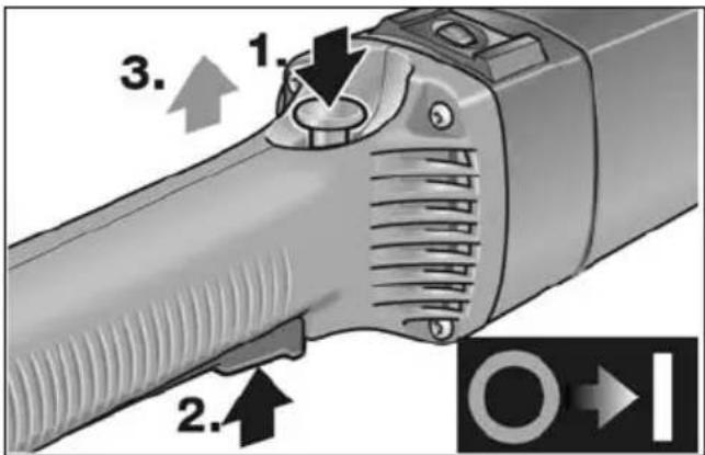
■ Press the switch (2.) and release the switch interlock (3.).
■ To switch off, release the switch.
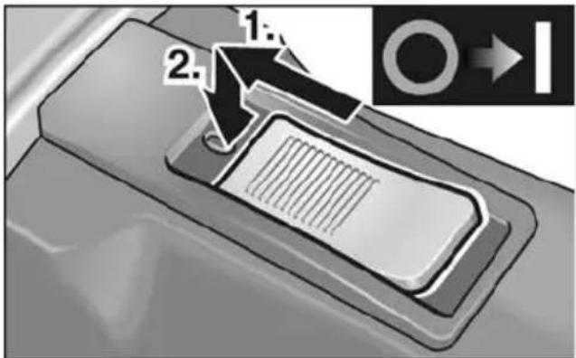
LST 1503 VR
Brief operation without engaged switch rocker:
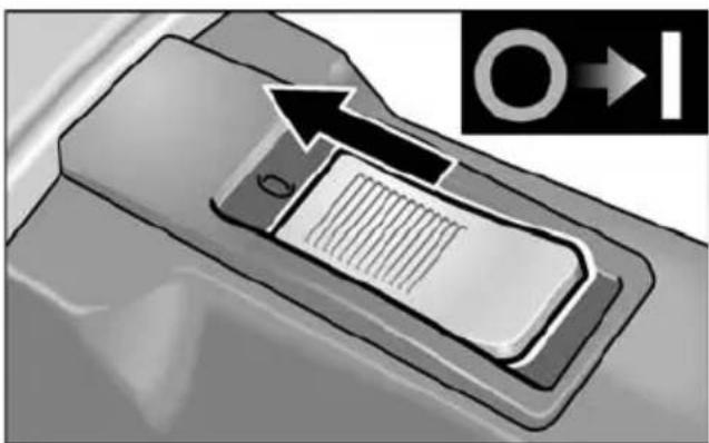
■ Push the switch rocker forwards and hold in position.
■ To switch off the power tool, release the switch rocker.
Continuous operation with engaged switch rocker:
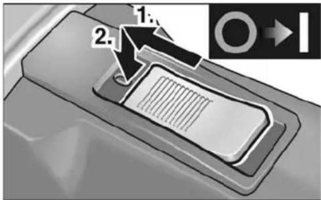
■ Push the switch rocker forwards and engage by pressing the front end.
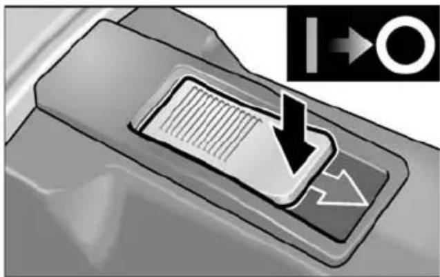
■ To switch off the power tool, release the switch rocker by pressing the rear end.
Overload protection
If an extremely brief overload occurs, the overload protection prevents damage to the motor by automatically switching the device off.
For further information on the manufacturer's products go to www.flex-tools.com.
Preselecting the speed
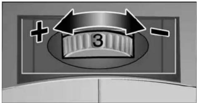
■ To set the operating speed, move the dial to the required value.
■ Gently press the switch to accelerate the power tool up to the preselected speed.
■ Always work in the lower speed area up to maximum setting 3.
i NOTE
If an overload or overheating occurs during continues operation, the power tool automatically reduces the speed until the power tool has cooled down adequately.
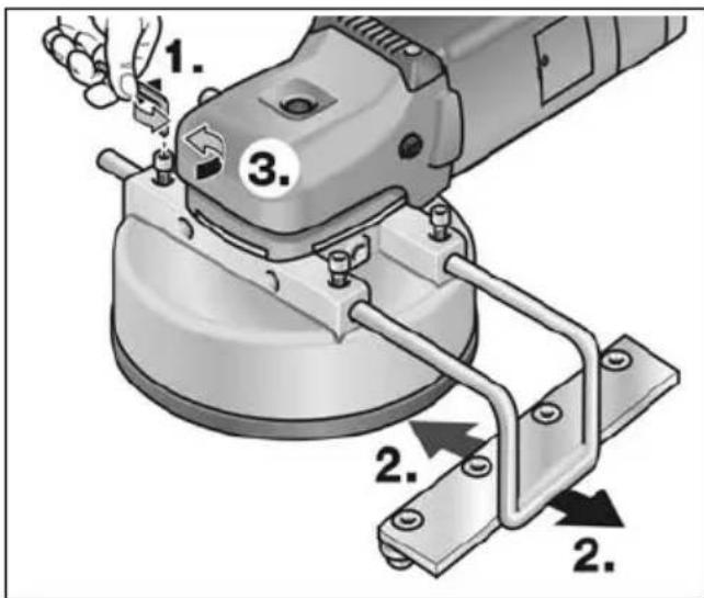
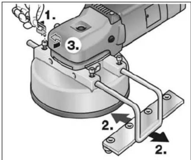
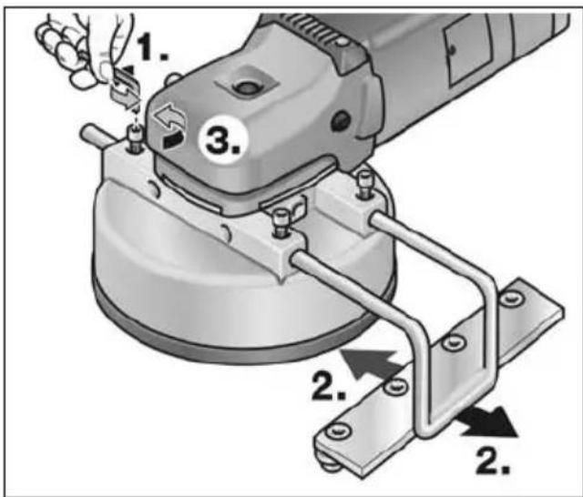
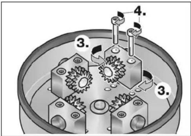
Setting working width
Different working widths can be set by attaching the bearing blocks with the carbide wheels in different positions.
■ Pull out the mains plug.
■ Loosen fastening screws on the bearing blocks (1.).
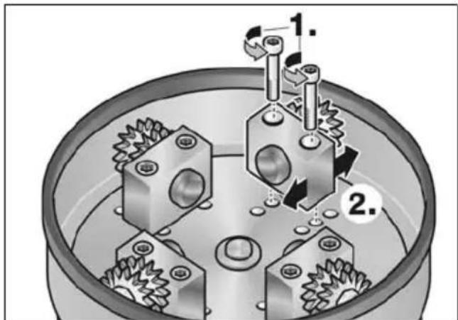
■ Attach bearing blocks in the required position (2.).
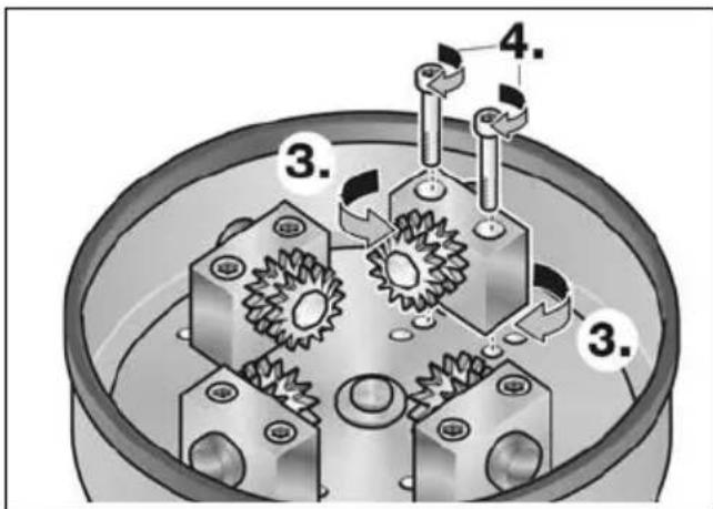
■ Align the carbide wheels inwards or outwards as required (3.) (LST 803 VR only).
■ Retighten fastening screws on the bearing blocks (4.).
Setting attachable stop
■ If required, loosen fastening screws (1.).
■ Push in the attachable stop sideways and set to the required working width (2.).
■ Retighten fastening screws (3.).
Dust extractor
CAUTION!
The bush hammering machine must be connected to a dust extractor during operation. The extraction system must be authorised to extract stone dust.
An authorised special extractor must be used to extract particularly harmful, carcinogenic, dry dust.
If the extraction system malfunctions, stop working immediately and switch off the power tool. Repair the fault before switching on the power tool again.

NOTE
It is recommended to use a FLEX Class M special extractor.
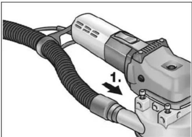
Take the hose included in delivery and pull the end without an adapter through the hose holder and connect to the connector (1.). Check the attachment!
■ Connect extraction hose of the extraction system to the adapter. Follow the operating instructions for the dust extraction system! Check the attachment! If required, use an appropriate adapter.

NOTE
If your dust extractor requires a special connection (i.e. a connection other than the 32 mm/36 mm standard connection which is included with the electric power tool), contact your dust extractor supplier to obtain the appropriate adapter.
Operating instructions

WARNING!
The milling head must not come into contact with sharp projecting objects. Danger of kick-back! Damage to milling head. If the milling head is damaged or severely worn, it must be replaced.

CAUTION!
Hold the electric power tool with both hands!
- If required, set working width.
- If required, set side stop.
- Connect dust extraction system.
- Insert mains plug.
-
Conduct a test run to check that the tool is attached correctly. Switch on the electric power tool (without locking the button) and leave it running for approx. 30 seconds. Check for imbalances and vibrations.
-
Set required speed.
- Switch on dust extraction system.
- Hold the electric power tool with both hands.
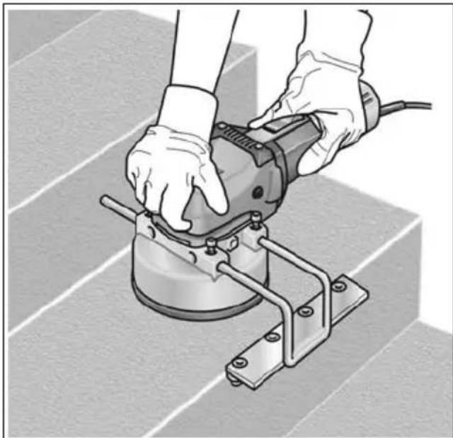
- Switch on the device.
■ Do not leave the electric power tool running too long in one place.
■ Always perform smooth stroke movements.
- Observe a minimum distance of 1 cm from the edge of the processed material.
Maintenance and care

WARNING!
Before performing any work on the electric power tool, pull out the mains plug.
Cleaning
Regularly clean the power tool and ventilation slots. Frequency of cleaning is dependent on the material and duration of use.
Regularly blow out the housing interior and motor with dry compressed air.
Carbon brushes
The electric power tool features cut-off carbon brushes.
When the cut-off carbon brushes reach their wear limit, the electric power tool switches off automatically.

NOTE
Use only original parts supplied by the manufacturer for replacement purposes. If non-original parts are used, the guarantee obligations of the manufacturer will be deemed null and void.
When the power tool is being used, the carbon brushes can be seen sparking through the rear air inlet apertures.
If the carbon brushes are sparking excessively, switch off the electric power tool immediately. Take your electric power tool to a customer service centre authorised by the manufacturer.
Gears

NOTE
Do not loosen the screws on the gear head during the warranty period.
Non-compliance will deem the guarantee obligations of the manufacturer null and void.
Repairs
Repairs may be carried out by an authorised customer service centre only.
Spare parts and accessories
Exploded drawings and spare-part lists can be found on our homepage:
www.flex-tools.com
Disposal information

WARNING!
Render redundant power tools unusable byremoving the power cord.

EU countries only
Do not throw electric power tools into the household waste!
In accordance with the European
Directive 2012/19/EC on Waste Electrical and Electronic Equipment and transposition into national law used electric power tools must be collected separately and recycled in an environmentally friendly manner.

NOTE
Please ask your dealer about disposal options!
CE-Declaration of Conformity
We declare under our sole responsibility that the product described under “Technical specifications” conforms to the following standards or normative documents:
EN 60745 in accordance with the regulations of the directives
2004/108/EC (until 19.04.2016),
2014/30/EU (from 20.04.2016),
2006/42/EC, 2011/65/EC.
Responsible for technical documents:
Exemption from liability
The manufacturer and his representative are not liable for any damage and lost profit due to interruption in business caused by the product or by an unusable product.
The manufacturer and his representative are not liable for any damage which was caused by improper use of the power tool or by use of the power tool with products from other manufacturers.
Table des matières
- Allumez l'appareil.
Manager Research & Development (R & D)
Klaus Peter WeinperEckhard F Head of Quality Department (QD)
29.05.2015
Manager Research &
Development (R & D)
29.05.2015
Klaus Peter WeinperEckhard F
Head of Quality
Department (QD)
Ajustar el tope desmontable
- Encender el equipo.
Manager Research & Development (R & D)
Klaus Peter WeinperEckhard F
Head of Quality Department (QD)
29.05.2015
Manager Research &
Development (R & D)
29.05.2015
Klaus Peter WeinperEckhard F
Head of Quality
Department (QD)
dB(A); WAARSCHUWING!
Klaus Peter WeinperEckhard F
Manager Research & Development (R & D)
Head of Quality Department (QD)
29.05.2015
■ Skub vippekontakten fremad og hold den fast.
■ Slip vippekontakten for at slukke.
Konstant drift med indgreb:
■ Frigør vippekontakten ved at trykke på bagerste ende for at slukke.
Overbelastningsbeskyttelse
■ Ved ekstrem kortvarig overbelastning forhindrer overbelastningsbeskyttelsen, at motoren beskadiges, da maskinen slukkes automatisk.
Monterbart anslag indstilles
- Tænd maskinen.
Manager Research & Development (R & D) 29.05.2015
Klaus Peter WeinperEckhard F Head of Quality Department (QD)
■ Skyv bryteren framover og hold den fast.
- Slå på maskinen.
■ Elektroverktøyet må ikke gå for lenge på ett sted.
Det må alltid føres jevnt med løftebevegelser.
Det må overholdes en minste avstand på 1 cm til kanten av det materialet som skal bearbeides.
Manager Research & Development (R & D) 29.05.2015
Klaus Peter WeinperEckhard F Head of Quality Department (QD)
Manager Research & Development (R & D)
Klaus Peter WeinperEckhard F
Head of Quality Department (QD)
29.05.2015
Klaus Peter WeinperEckhard F
Manager Research &
Development (R & D)
29.05.2015
Manager Research & Development (R & D)
Klaus Peter WeinperEckhard F Head of Quality Department (QD)
29.05.2015
2006/42/WE, 2011/65/WE.
Manager Research & Development (R & D)
Klaus Peter WeinperEckhard F
Head of Quality
Department (QD)
29.05.2015
Manager Research & Development (R & D)
Klaus Peter WeinperEckhard F
Head of Quality Department (QD)
29.05.2015
- Zapněte nářadí.
■ Vyskrutkujte upevňovacie skrutky ložiskových stojanov (1.).
■ Namontujte ložiskové stojany do požadovaných polôh (2.).
Kolieska z tvrdokovu pri tom nasmerujte podl'a potreby smerom dovnútra alebo von (3.) (iba LST 803 VR).
■ Upevňovacie skrutky ložiskových stojanov opät utiahnite (4.).
■ Pretiahnite hadicu obsiahnutú v rozsahu dodávky koncom bez adaptéra hadicovým držiakom a pripojte ju na pripojovacie hrdlo (1.). Skontrolujte upevnenie!
Pripojte hadicu odsávacieho zariadenia na adaptér. Dodržiavajte návod na obsluhu odsávacieho zariadenia!
Skontrolujte upevnenie! V prípade potreby použite vhodný adaptér.
i UPOZORNENIE
- Zapnite náradie.
- Lülitada seade sisse.
Klaus Peter WeinperEckhard F
Manager Research & Development (R & D)
Head of Quality
Department (QD)
29.05.2015
Manager Research & Development (R & D)
Klaus Peter WeinperEckhard F
Head of Quality
Department (QD)
29.05.2015
- Ierīces ieslēgšana.
Klaus Peter WeinperEckhard F
Manager Research & Development (R & D)
Head of Quality Department (QD)
29.05.2015


- SYMBOLS USED IN THIS MANUAL
- WARNING
- CAUTION
- NOTE
- SYMBOLS ON THE POWER TOOL
- OVERVIEW
- FOR YOUR SAFETY
- INTENDED USE
- SAFETY INSTRUCTIONS FOR BUSH HAMMERING MACHINES
- KICKBACK AND RELATED WARNINGS
- SPECIAL SAFETY INSTRUCTIONS FOR MILLING
- ADDITIONAL SAFETY INSTRUCTIONS
- DAMAGE TO PROPERTY
- NOISE AND VIBRATION
- OPERATING INSTRUCTIONS
- BEFORE SWITCHING ON THE POWER TOOL
- SWITCHING ON AND OFF
- LST 803 VR
- LST 1503 VR
- BRIEF OPERATION WITHOUT ENGAGED SWITCH ROCKER
- CONTINUOUS OPERATION WITH ENGAGED SWITCH ROCKER
- OVERLOAD PROTECTION
- PRESELECTING THE SPEED
- I NOTE
- SETTING WORKING WIDTH
- SETTING ATTACHABLE STOP
- DUST EXTRACTOR
- MAINTENANCE AND CARE
- CLEANING
- CARBON BRUSHES
- GEARS
- REPAIRS
- SPARE PARTS AND ACCESSORIES
- DISPOSAL INFORMATION
- CE-DECLARATION OF CONFORMITY
- EXEMPTION FROM LIABILITY
- TABLE DES MATIÈRES
- KONSTANT DRIFT MED INDGREB
- OVERBELASTNINGSBESKYTTELSE
- MONTERBART ANSLAG INDSTILLES
- I UPOZORNENIE
Brand : Flex
Model : LST 1503 VR
Category : Drill